

Advantech ADAM CPU 821 NET, ADAM CPU 821 DP, ADAM CPU 821 DPM, ADAM CPU 8214, ADAM CPU 8215 Series Manual
...Page 1

CPU ADAM 821x Chapter 1 Principles
Chapter 1 Principles
Outline
Contents
This introduction contains references on the handling and information about
application areas and usage of the CPU modules.
It also provides certain suggestions on the approach when programming
the module and the CPU specifications that are important in this respect.
Below follows a description of:
• Safety information for users
• Construction and operation of the CPU 821x
• Programming principles
Topic Page
Chapter 1 Principles ............................................................................... 1-1
Safety information for users................................................................... 1-2
Hints for the deployment of the MPI interface........................................ 1-3
Hints for the deployment of the Green Cable ........................................ 1-4
Overview System 82xx .......................................................................... 1-5
General description of the System 82xx................................................ 1-6
Overview CPU 821x .............................................................................. 1-7
Hints for project engineering.................................................................. 1-8
Application fields.................................................................................. 1-11
Features .............................................................................................. 1-12
Operating modes of a CPU.................................................................. 1-13
CPU 821x programs ............................................................................ 1-14
CPU 821x operands ............................................................................ 1-14
ADAM 8000 Manual CPU 821x – Rev 1.1 1-1
Page 2

Chapter 1 Principles CPU ADAM 821x
Safety information for users
Handling of
electrostatically
sensitive modules
Shipping of
modules
ADAM modules make use of highly integrated components in MOStechnology. These components are extremely sensitive to over-voltages
that may occur during electrostatic discharges.
The following symbol is attached to modules that can be destroyed by
electrostatic discharges:
The symbol is located on the module, the module rack or on packing
material and it indicates the presence of electrostatically sensitive
equipment.
It is possible that electrostatically sensitive equipment is destroyed by
energies and voltages that are far less than the human threshold of
perception. These voltages may occur where persons do not discharge
themselves before handling electrostatically sensitive modules and they
may damage components thereby causing the module to become
inoperable or unusable. Modules that have been damaged by electrostatic
discharge are usually not detected immediately. The respective failure may
become apparent after a period of operation.
Components damaged by electrostatic discharges can fail after a
temperature change, mechanical shock or changes in the electrical load.
Only the consistent implementation of protective devices and meticulous
attention to the applicable rules and regulations for handling the respective
equipment is able to prevent failures of electrostatically sensitive modules.
Please ship the modules exclusively in the original packing material.
Measurements
and alterations on
electrostatically
sensitive modules
1-2 ADAM 8000 Manual CPU 821x – Rev 1.1
When you are conducting measurements on electrostatically sensitive
modules you should take the following precautions:
• Floating instruments must be discharged before use.
• Instruments must be grounded.
You should only use soldering irons with grounded tips when you are
making modifications on electrostatically sensitive modules.
Attention!
Personnel and instruments should be grounded when working on
electrostatically sensitive modules.
Page 3

CPU ADAM 821x Chapter 1 Principles
Hints for the deployment of the MPI interface
2
What is MP
I?
Deployment as
MP interface
The MP
2
I jack combines 2 interfaces in 1:
• MP interface
• RS232 interface
Please regard that the RS232 functionality is only available by using the
Green Cable from Advantech.
The MP interface provides the data transfer between CPUs and PCs. In a
bus communication you may transfer programs and data between the
CPUs interconnected via MPI.
Connecting a common MPI cable, the MPI jack supports the full MPI
functionality.
Important notes for the deployment of MPI cables!
Deploying MPI cables at the ADAM CPUs from Advantech, you have to
make sure that Pin 1 is not connected. This may cause transfer problems
and in some cases damage the CPU!
Especially Profibus cables from Siemens, like e.g. the 6XV1 830-1CH30,
must not be deployed at MP
2
I jack.
For damages caused by nonobservance of these notes and at improper
deployment, ADAM does not take liability!
Deployment as
RS232 interface only
via "Green Cable"
For the serial data transfer from your PC, you normally need a MPI
transducer. Fortunately you may also use the "Green Cable" from
Advantech You can order this under the order no. ADAM-8950-0KB00.
The "Green Cable" supports a serial point-to-point connection for data
transfer via the MP
2
I jack exclusively for ADAM 8xxx CPUs.
Please regard the hints for the deployment of the "Green Cable" on the
following page.
ADAM 8000 Manual CPU 821x – Rev 1.1 1-3
Page 4

Chapter 1 Principles CPU ADAM 821x
Hints for the deployment of the Green Cable
What is the
Green Cable?
The Green Cable is a green connection cable, manufactured exclusively for
the deployment at ADAM System components.
The Green Cable is a programming and download cable for ADM CPUs
8xxx and ADAM fieldbus masters. The Green Cable from Advantech is
available under the order no. ADAM-8950-0KB00.
The Green Cable allows you to:
• transfer projects serial
Avoiding high hardware needs (MPI transducer, etc.) you may realize a
serial point-to-point connection via the Green Cable and the MP
This allows you to connect components to your ADAM CPU that are able
to communicate serial via an MPI adapter like e.g. a visualization
system.
• execute firmware updates of the CPUs and fieldbus masters
Via the Green Cable and an upload application you may update the
firmware of all recent CPUs 8xxx and certain fieldbus masters (see
Note).
Important notes for the deployment of the Green Cable
Nonobservance of the following notes may cause damages on system
components.
For damages caused by nonobservance of the following notes and at
improper deployment, Advantech does not take liability!
2
I jack.
Note to the application area
The Green Cable may exclusively deployed directly
1-4 ADAM 8000 Manual CPU 821x – Rev 1.1
of the ADAM components (in between plugs are not permitted).
At this time, the following components support the Green Cable:
CPUs 8xxx and the fieldbus masters ADAM 8208-1xx01 from Advantech.
Note to the lengthening
The lengthening of the Green Cable with another Green Cable res. The
combination with further MPI cables is not permitted and causes damages
of the connected components!
The Green Cable may only be lengthened with a 1:1 cable (all 9 Pins are
connected 1:1).
at the concerning jacks
Page 5
CPU ADAM 821x Chapter 1 Principles
Overview System 82xx
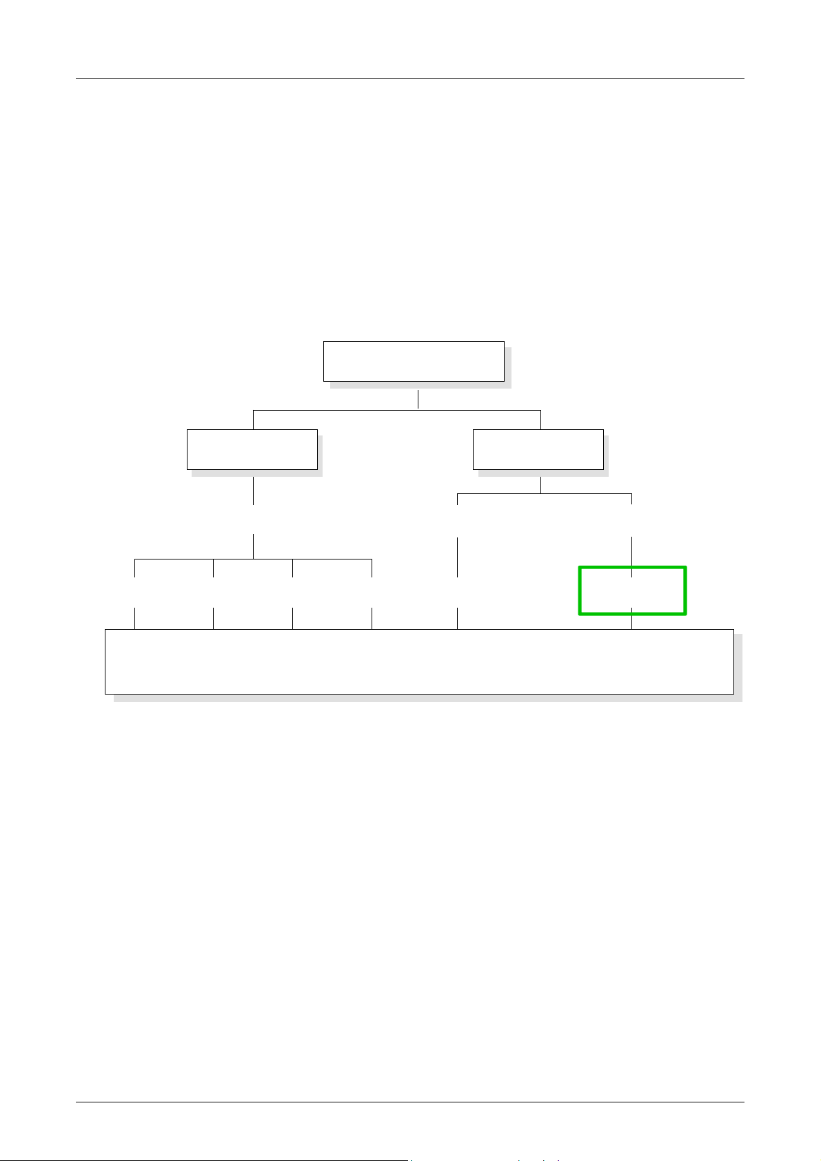
The System 82xx
The System 82xx is a modular automation system for low and middle range
of performance that you may use either centralized or decentralized. The
single modules are directly clipped to a 35mm DIN rail and are connected
together with the help of special bus clips.
The following picture shows the range of performance of the System82xx:
System 8000
decentral
DP 8xxx
Profibus DeviceNet CAN Interbus PC-CPU PLC-CPU
on demand
on demand
PC 8xxx
central
PLC 8xxx
for STEP®7 of Siemens
Overview
Manuals
peripheral
Dig. IN / Dig. OUT / Anal. IN / Anal. OUT / FM / CP
The current manual describes the PLC-CPU family CPU 821x compatible to
STEP
The peripheral modules, PCs and decentralized peripheral equipment are
to find in the manual HB97 "System82xx". This manual also contains hints
for installation and commissioning of the System82xx.
7 by Siemens.
ADAM 8000 Manual CPU 821x – Rev 1.1 1-5
Page 6

Chapter 1 Principles CPU ADAM 821x
General description of the System 82xx
Structure /
Dimensions
Installation
• Norm profile head rail 35mm
• Peripheral modules with labeling strip
• Measurements basic module:
Single width: (HxWxD) in mm: 76x25.4x76; in inches: 3x1x3
Double width: (HxWxD) in mm: 76x50.8x76; in inches: 3x2x3
Please note, that you have to plug in the CPU only at plug-in location 1
resp. 1 and 2 (if double width).
1
2
3
[1] CPU if double width
[2] CPU single width
[3] peripheral modules
[4] leading bars
D
V
I
M
E
M
O
ER
R
Y
RD
D
K
DE
P
B
D
NET
X2
X2
34
34
ADAM-8216-2BP01
VIPA 288-2BL10
4
IM 253 CAN
CPU 8216
PW
R
ER
S
RD
BA
PW
SF
FC
MC
ADR.
DC24V
+
DC
+
24V
-
X5
-
X2
67
34
VIPA 253-1CA00
ADAM-8216-2BA01
PC 288
CPU 8216 DP
R
PW
S
RN
BA
PW
SF
FC
M
O
MC
U
S
E
OFF
D
DC
+
C
+
24V
24
-
-
V
MMC
01
MMC
RN
ST
MR
M
2
P
I
X1
1
1
2
2
RN
C
ST
O
MR
M
1
M
2
P
I
ON
X1
1
2
SM 8221
DI 8xDC24V
.0
.1
.2
.3
.4
.5
.6
.7
X2
34
ADAM-8221-1BF00
SM 8221
DI 8xDC24V
.0
.1
.2
.3
.4
.5
.6
.7
X2
34
ADAM-8221-1BF00
SM 8221
DI 8xDC24V
1
.0
2
.1
3
.2
4
.3
5
.4
6
.5
7
.6
8
.7
9
I0
X2
34
ADAM-8221-1BF00
SM 8221
DI 8xDC24V
1
.0
2
.1
3
.2
4
.3
5
.4
6
.5
7
.6
8
.7
9
I0
X2
34
ADAM-8221-1BF00
SM 8221
DI 8xDC24V
1
.0
2
.1
3
.2
4
.3
5
.4
6
.5
7
.6
8
.7
9
I0
X2
34
ADAM-8221-1BF00
SM 8221
DI 8xDC24V
1
.0
2
.1
3
.2
4
.3
5
.4
6
.5
7
.6
8
.7
9
I0
X2
34
ADAM-8221-1BF00
SM 8221
DI 8xDC24V
1
.0
2
.1
3
.2
4
.3
5
.4
6
.5
7
.6
8
.7
9
I0
X2
34
ADAM-8221-1BF00
SM 8221
DI 8xDC24V
1
.0
2
.1
3
.2
4
.3
5
.4
6
.5
7
.6
8
.7
9
I0
X2
34
ADAM-8221-1BF00
1
2
3
4
5
6
7
8
9
I0
1
2
3
4
5
6
7
8
9
I0
Operating security
• Plug in via CageClamps at the front-facing connector, core cross-section
0.08...2.5mm
2
resp. 1.5 mm2 (18pin plug)
• Total isolation of the cables during module changes
• Potential separation of all modules to the backplane bus
• EMC-proof ESD/Burst acc. EN61000-4-2/EN61000-4-4
to Level 3: 8kV/2.5kV
• Shock resistance acc. IEC 60068-2-6 / IEC 60068-2-27 (1G/12G)
Environmental
conditions
• Operating temperature: 0... +55°C
• Storage temperature: -40... +85°C
• Relative humidity: 95% without condensation
• fan-less operation
1-6 ADAM 8000 Manual CPU 821x – Rev 1.1
Page 7

CPU ADAM 821x Chapter 1 Principles
Overview CPU 821x
Products
Performance
specification
Data CPU 8214 CPU 8215 CPU 8216
RAM 40kByte 80kByte 192kByte
Load memory 32kByte 64kByte 128kByte
Cycle time, bit/word operations 0.18µs / 0.78µs
Bit memory/marker 2048Bit (M0.0...M255.7)
Timer 128 (T0...T127)
Counter 256 (Z0...Z255)
Number of blocks FB / FC / DB 1024 / 1024 / 2047
Total addressing space
inputs / outputs
PA Inputs 1024Bit (E0.0...E127.7)
PA Outputs 1024Bit (A0.0...A127.7)
Order data
CPU 21x ADAM-8214-1BA01 ADAM-8215-1BA01 ADAM-8216-1BA01
CPU 21xNET ADAM-8214-2BT01 ADAM-8215-2BT01 ADAM-8216-2BT01
CPU 21xDPM ADAM-8214-2BM01 ADAM-8215-2BM01 ADAM-8216-2BM01
CPU 21xDP ADAM-8214-2BP01 ADAM-8215-2BP01 ADAM-8216-2BP01
General
information
The ADAM CPU 821x is available in four different versions also differing in
view:
• CPU 821x PLC-CPU
• CPU 821xNET PLC-CPU with Ethernet interface
• CPU 821xDPM PLC-CPU with Profibus-DP master
• CPU 821xDP PLC-CPU with Profibus-DP slave
Every CPU 821x is available in 3 CPU performance specifications: 214,
215 and 216. There is no visual difference between these units. The
performance of the CPU 821x increases along with an increase of the
number.
1024 / 1024 with 128Byte process image (PA) each
Note!
If not especially specified, the information in this manual refers to all the
CPUs of the ADAM CPU 821x family!
The instruction set of the CPU 821x is compatible with STEP
and is being configured by means of the Siemens STEP
7 of Siemens
7 manager. A
large function library is included with the CPU.
The CPU employs a Multi Media Card (MMC) as external storage medium.
The MMC is available from Advantech.
The project engineering of the Ethernet components takes place by means
of the ADAM project configuration tool WinNCS. The data may be
transferred into the CPU via MPI.
The CPU 821x has an integrated power supply that requires DC 24V via
the front panel. It is protected against reverse polarity and short circuits.
ADAM 8000 Manual CPU 821x – Rev 1.1 1-7
Page 8

Chapter 1 Principles CPU ADAM 821x
Hints for project engineering
Outline
Preconditions
For the project engineering of the CPU 821x and the other System 82xx
modules connected to the same bus, you use the hardware configurator
from Siemens.
To address the directly plugged peripheral modules, you have to assign a
special address in the CPU to every one.
The address allocation and the parameterization of the modules takes
place in the STEP
7 manager from Siemens in form of a virtual Profibus
system. For the Profibus interface is standardized software sided, the
functionality is guaranteed by including a GSD-file into the STEP
7
manager from Siemens.
Transfer your project into the CPU via the MPI interface.
For the project engineering of your CPU 821x the following requirements
have to be fulfilled:
• STEP
7 manager from Siemens is installed at your PC resp. PU.
• The GSD-file for the System 82xx is included to the hardware
configurator
• serial connection to the CPU (e.g. via "Green Cable")
Note!
The configuration of the CPU requires a thorough knowledge of the
Siemens STEP
7 manager and the hardware configurator!
Compatibility to
STEP
7 manager
from Siemens via
GSD-file
®
The CPU 821x is configurable via the STEP7
manager from Siemens.
This means the programming and parameterization of a System ADAM
82xx and the parameterization and project engineering under Profibus-DP.
The project engineering of a CPU 821x takes place via the STEP
®
7 manager from Siemens in form of a virtual Profibus system with the CPU 3152DP as basic.
Due to the standardized Profibus interface ADAM is able to support the
complete functionality of the System 82xx family in the STEP
®
7 manager
from Siemens by including a GSD-file.
To be compatible with the STEP7 configuration tool from
Siemens, the following steps have to take place:
• Project the Profibus-DP master system with CPU 315-2DP
(6ES7 315-2AF01).
• Add Profibus slave with address 1.
• Include the CPU 821x at slot 0 of the slave system.
1-8 ADAM 8000 Manual CPU 821x – Rev 1.1
Page 9

CPU ADAM 821x Chapter 1 Principles
Project
engineering
CPU 821x with
central periphery
The following steps are necessary to project a CPU 821x in the hardware
configurator from Siemens:
• Start the hardware configurator from Siemens
• Load the delivered ADAM GSD-file from Advantech
• Create a Profibus-DP master system with the CPU 315-2DP
• Include the slave system "ADAM_DP8000" from the hardware catalog in
your master system. You find this slave system in the hardware catalog
under Profibus-DP > Additional field devices > I/O > ADAM
• Assign the address 1 to your slave system, so that the CPU is able to
recognize the system as central periphery system
• Add your modules to the slave system in the same order you have
assembled them. Start with the CPU at plug-in location 0
• Include your System 82xx modules starting at plug-in location 1
CPU 821x
DP200V
Slot Module
PBAdr.:2
PBAdr.:1
Master projecting
of the CPU
821xDPM
0 821x-xxxx
1
. Expansion
. modules
.
3
When projecting a CPU 821xDPM you include the central modules like
described above. Slave systems that shall be connected to the master are
added to the already existing master system:
CPU 821xDPM central
DP slaves decentral ...
ADAM 821x ADAM821xDP
PBAdd.:2
PBAdd.:1
DP200V
Slot M odule
0 821x-2BM0 1
1
. ce ntral
. pe riphery
.
32
DP200V
PBAdr.:3 ... 12 5
ADAM 8000 Manual CPU 821x – Rev 1.1 1-9
Page 10

Chapter 1 Principles CPU ADAM 821x
Project
engineering of the
CPU 821xDP in a
master system
Master system
When configuring a CPU 821xDP, the central plugged-in modules are
parameterized like shown above.
Slave parameterization
As intelligent slave, the Profibus section maps its data areas into the
memory area of the CPU 821xDP. The assignment of the areas is fixed via
the propierties of the CPU 821xDP. These areas have to be provided with
an according PLC program.
Attention!
The length values of input and output area have to be identical to the byte
values of the master project engineering. Otherwise no Profibus communication is possible (slave failure).
Steps of project engineering in the DP master
• Configure the CPU with DP master system (address 2)
• Add Profibus slave 821xDP (GSD-file required)
• Assign Profibus input and output area starting with plug-in location 0
The following picture illustrates the project engineering:
Slave System
PBAddr.:2
Slot Module
0 Output (Bytes)
1 Input (Bytes)
Master projecting
of the CPU
821xNET
CPU21x
PBAddr.:3
PBAddr.:1
Slot Module
0 CPU 821xDP
1
. Expansion
. modules
.
3
The project engineering of network connections via TCP/IP takes place via
the configuration tool WinNCS from Advantech.
DP200V
1-10 ADAM 8000 Manual CPU 821x – Rev 1.1
Page 11

CPU ADAM 821x Chapter 1 Principles
Application fields
This series of CPU modules provides access to the peripheral modules of
the ADAM System 8xxx. You can use a set of standard commands and
programs to interrogate sensors and actuators. One single CPU may
address a maximum of central 32 modules.
Application
example
Compact centralized configuration
CPU
AI 4 AO 4 DIO 8 DO 16
CPU 21x
DO 8 Count
Decentralized configuration using Profibus
CPU IM 208
1,3
IM 253
Input/output periphery
1
CPU IM 208
2,4
IM 253
Input/output periphery
4
IM 253
Input/output periphery
2
CPU IM 208
Input/output periphery
5
CPU 21x DP
Input/output periphery
3
CPU 21x DP
Input/output periphery
5
ADAM 8000 Manual CPU 821x – Rev 1.1 1-11
Page 12

Chapter 1 Principles CPU ADAM 821x
Application based on TCP/IP or H1
Visualization and
shop floor data collection
via DDE-server
H1 / TCP/IP
TCP/IP/H1
Hub
Features
System 82xx
CPU 821x NET
System 82xx
H1 / TCP/IP
CPU 821x NET
The PLC-CPUs are employed as program executor.
They support the input/output modules and process the data from the
function modules.
• Quick programming due to the compatibility with Siemens STEP
7.
• The compact construction requires less space.
• Enhanced flexibility provided by up to 32 function modules (DIG I/O,
ANA I/O, SSI, pulse counter, communication modules, etc.).
• Additional function modules can be added quickly and easily by means
of plug-in bus extension options.
• User-friendly maintenance using a PC via MPI.
• Optional Ethernet or Profibus interface.
1-12 ADAM 8000 Manual CPU 821x – Rev 1.1
Page 13

CPU ADAM 821x Chapter 1 Principles
Operating modes of a CPU
General
Cyclic processing
Timer processing
These CPUs are intended for small and medium sized applications and are
supplied with an integrated 24V power supply. The CPU contains a
standard processor with internal program memory. In combination with the
System 82xx peripherals the unit provides a powerful solution for process
automation applications within the System 82xx family.
A CPU supports the following modes of operation:
• cyclic processing
• timer processing
• alarm controlled processing
• priority based processing
Cyclic processing represents the major portion of all the processes that are
executed in the CPU. Identical sequences of operations are repeated in a
never ending cycle.
Where a process requires control signals at constant intervals you can initiate
certain operations based upon a timer, e.g. not critical monitoring functions
at one-second intervals.
Alarm controlled
operation
Priority based
processing
If a process signal requires a quick response you would allocate this signal
to an alarm controlled procedure. An alarm may activate a procedure in
your program.
The above processes are handled by the CPU in accordance with their
priority. Since a timer or an alarm event requires a quick reaction the CPU
will interrupt the cyclic processing when these high-priority events occur to
react to the event. Cyclic processing will resume once the reaction has
been processed. This means that cyclic processing has the lowest priority.
ADAM 8000 Manual CPU 821x – Rev 1.1 1-13
Page 14

Chapter 1 Principles CPU ADAM 821x
CPU 821x programs
Overview
System routine
User program
The program that is present in every CPU is divided as follows:
• System routine
• User program
The system routine organizes all those functions and procedures of the
CPU that are not related to a specific control application.
This consists of all the functions that are required for the processing of a
specific control application. The operating modules provide the interfaces to
the system routines.
CPU 821x operands
Overview
The following operands are available for programming the CPU 821x:
• Process image and periphery
• Bit memory/marker
• Timers and counters
• Data blocks
Process image
and periphery
1-14 ADAM 8000 Manual CPU 821x – Rev 1.1
The user program can quickly access the process image of the inputs and
outputs PAA/PAE. You may manipulate the following types of data:
- individual bits
- bytes
- words
- double words
You may also gain direct access to peripheral modules via the bus from
your user program. The following types of data are available:
- bytes
- words
- blocks
Page 15

CPU ADAM 821x Chapter 1 Principles
Bit memory
Timer and counter
Data blocks
Bit memory is an area of memory that is accessible to the user program by
means of certain operations. Bit memory is intended to store frequently
used working data.
You may access the following types of data:
- individual bits
- bytes
- words
- double words
With your program you may load a time cell with a value between 10ms and
9990s. As soon as the user program executes a start operation the value of
this timer is decremented by the interval that you have specified until it
reaches zero.
You may load counter cells with an initial value (max. 999) and increment
or decrement this when required.
A data block contains constants or variables in form of bytes, words or
double words. You may always access the current data block by means of
operands.
You may access the following types of data:
- individual bits
- bytes
- words
- double words
ADAM 8000 Manual CPU 821x – Rev 1.1 1-15
 Loading...