

Page 1

User Manual
ADAM 4000 Series
Data Acquisition Modules
Page 2

Copyright
Part No. XXXXXXXXXX Edition 1
Printed in Taiwan November 2015
The documentation and the software included with this product are copyrighted 2013
by Advantech Co., Ltd. All rights are reserved. Advantech Co., Ltd. reserves the right
to make improvements in the products described in this manual at any time without
notice. No part of this manual may be reproduced, copied, translated or transmitted
in any form or by any means without the prior written permission of Advantech Co.,
Ltd. Information provided in this manual is intended to be accurate and reliable. However, Advantech Co., Ltd. assumes no responsibility for its use, nor for any infringements of the rights of third parties, which may result from its use.
Acknowledgements
ADAM is a trademark of Advantech Co., Ltd.
IBM and PC are trademarks of International Business Machines Corporation.
All other product names or trademarks are properties of their respective owners.
Product Warranty (2 years)
Advantech warrants to you, the original purchaser, that each of its products will be
free from defects in materials and workmanship for two years from the date of purchase.
This warranty does not apply to any products which have been repaired or altered by
persons other than repair personnel authorized by Advantech, or which have been
subject to misuse, abuse, accident or improper installation. Advantech assumes no
liability under the terms of this warranty as a consequence of such events.
Because of Advantech’s high quality-control standards and rigorous testing, most of
our customers never need to use our repair service. If an Advantech product is defective, it will be repaired or replaced at no charge during the warranty period. For outof-warranty repairs, you will be billed according to the cost of replacement materials,
service time and freight. Please consult your dealer for more details.
If you think you have a defective product, follow these steps:
1. Collect all the information about the problem encountered. (For example, CPU
speed, Advantech products used, other hardware and software used, etc.) Note
anything abnormal and list any onscreen messages you get when the problem
occurs.
2. Call your dealer and describe the problem. Please have your manual, product,
and any helpful information readily available.
3. If your product is diagnosed as defective, obtain an RMA (return merchandize
authorization) number from your dealer. This allows us to process your return
more quickly.
4. Carefully pack the defective product, a fully-completed Repair and Replacement
Order Card and a photocopy proof of purchase date (such as your sales receipt)
in a shippable container. A product returned without proof of the purchase date
is not eligible for warranty service.
5. Write the RMA number visibly on the outside of the package and ship it prepaid
to your dealer.
ADAM-4000 Series User Manual ii
Page 3

Declaration of Conformity
CE
The ADAM-4000 series developed by Advantech Co., Ltd. has passed the CE test for
environmental specifications when operated within an industrial enclosure (ADAM4950-ENC). Therefore, in order to protect the ADAM modules from being damaged
by ESD (Electric Static Discharge), we strongly recommend that the use of CE-compliant industrial enclosure products when using any ADAM module.
Technical Support and Assistance
1. Visit the Advantech web site at www.advantech.com/support where you can find
the latest information about the product.
2. Contact your distributor, sales representative, or Advantech's customer service
center for technical support if you need additional assistance. Please have the
following information ready before you call:
– Product name and serial number
– Description of your peripheral attachments
– Description of your software (operating system, version, application software,
etc.)
– A complete description of the problem
– The exact wording of any error messages
iii ADAM-4000 Series User Manual
Page 4

ADAM-4000 Series User Manual iv
Page 5

Contents
Chapter 1 Introduction..........................................1
1.1 Overview ................................................................................................... 2
1.2 Applications............................................................................................... 3
Chapter 2 Installation Guideline ..........................5
2.1 System Requirements to Set up an ADAM Network................................. 6
Figure 2.1 Power Supply Connections ........................................ 7
2.2 Basic Configuration and Hook-up ............................................................. 9
Figure 2.2 Basic Hook-up of ADAM Module to Host Switches .... 9
2.3 Baud Rate and Checksum ...................................................................... 11
Figure 2.3 Grounding the INIT* Terminal................................... 12
Figure 2.4 Set INIT switch to “Init” ............................................. 12
2.4 Multiple Module Hookup.......................................................................... 13
Figure 2.5 Multi-module Connection.......................................... 13
2.5 Programming Example............................................................................ 14
Chapter 3 I/O Modules ........................................21
3.1 The Common Specification of ADAM-4000 I/O Series ........................... 22
3.2 ADAM-4011/4011D Thermocouple Input Modules ................................. 22
3.2.1 ADAM-4011D Thermocouple Input Module ................................ 25
Figure 3.1 ADAM-4011 Thermocouple Input Module ................ 25
3.2.2 ADAM-4011D Thermocouple Input Module ................................ 26
Figure 3.2 ADAM-4011D Thermocouple Input Module with LED
Display...................................................................... 26
3.2.3 Application Wiring ....................................................................... 27
Figure 3.3 ADAM-4011/4011D Thermocouple Input Wiring Dia-
gram ......................................................................... 27
Figure 3.4 ADAM-4011/4011D Millivolt and Volt Input Wiring Dia-
gram ......................................................................... 27
Figure 3.5 ADAM-4011/4011D Process Current Input Wiring Dia-
gram ......................................................................... 27
Figure 3.6 ADAM-4011/4011D Digital Output Wiring Diagram
Used with SSR (HI-LO alarm) .................................. 28
Figure 3.7 ADAM-4011/4011D Digital Input Wiring Diagram Used
with TTL.................................................................... 28
Figure 3.8 ADAM-4011/4011D Digital Input Wiring Diagram Used
with Dry contact ........................................................ 28
3.3 ADAM-4012 Analog Input Module........................................................... 29
3.3.1 ADAM-4012 Analog Input Module .............................................. 30
Figure 3.9 ADAM-4012 Analog Input Module ............................ 30
3.3.2 Application Wiring ....................................................................... 31
Figure 3.10ADAM-4012 Millivolt and Volt Input Wiring Diagram 31
Figure 3.11ADAM-4012 Process Current Input Wiring Diagram 31
Figure 3.12ADAM-4012 Digital Output Wiring Diagram Used with
SSR (HI-LO alarm) ................................................... 31
Figure 3.13ADAM-4012 Digital Input Wiring Diagram Used with
TTL ........................................................................... 32
Figure 3.14ADAM-4012 Digital Input Wiring Diagram Used with
Dry contact ............................................................... 32
3.4 ADAM-4013 RTD Module ....................................................................... 33
Figure 3.15ADAM-4013 RTD Input Module................................ 33
v ADAM-4000 Series User Manual
Page 6

3.4.1 Application Wiring ....................................................................... 34
Figure 3.16ADAM-4013 RTD Inputs Wiring Diagram................. 34
3.5 ADAM-4015 6-channel RTD Input Module ............................................. 35
Figure 3.17ADAM-4015 6-channel RTD Input Module ............... 35
3.5.1 Application Wiring ....................................................................... 36
Figure 3.18ADAM-4015 RTD Input Module Wiring Diagram...... 36
3.5.2 Technical specification of ADAM-4015 ....................................... 37
Table 3.1: Technical Specification of ADAM-4015 .................... 37
3.6 ADAM-4015T 6-channel Thermistor Input Module ................................. 38
Figure 3.19ADAM-4015T 6-channel Thermistor Input Module... 38
3.6.1 Application Wiring ....................................................................... 38
Figure 3.20ADAM-4015T Thermistor Input Module Wiring Diagram
38
3.6.2 Technical Specification of ADAM-4015T .................................... 39
Table 3.2: Technical Specification of ADAM-4015T .................. 39
3.7 ADAM-4016 Analog Input/Output Module............................................... 40
Figure 3.21ADAM-4016 Analog Input/Output Module ................ 41
3.7.1 Application Wiring ....................................................................... 42
Figure 3.22ADAM-4016 Strain Gauge Voltage Input Wiring Dia-
gram ......................................................................... 42
Figure 3.23ADAM-4016 Strain Gauge Current Input Wiring Dia-
gram ......................................................................... 42
Figure 3.24ADAM-4016 Digital Output Wiring Diagram Used with
SSR .......................................................................... 42
3.8 ADAM-4017/4017+/4018/4018M/4018+ 8-channel Analog Input Modules.
43
3.8.1 ADAM-4017/4018 8-channel Analog Input Module .................... 43
3.8.2 ADAM-4018M 8-channel Analog Input Data logger.................... 43
3.8.3 ADAM-4017+ 8-channel Differential Analog Input Module ......... 43
3.8.4 ADAM-4018+ 8-channel Thermocouple Input Module ............... 44
3.8.5 ADAM-4017 8-channel Analog Input Module ............................. 44
Figure 3.25ADAM-4017 8-channel Analog Input Module ........... 44
3.8.6 ADAM-4017+ 8-channel Differential Analog Input Module ......... 45
Figure 3.26ADAM-4017+ 8-ch. differential analog input module 45
Table 3.3: Technical Specification of ADAM-4017+ .................. 46
3.8.7 ADAM-4018 8-channel Analog Input Module ............................. 46
Figure 3.27ADAM-4018 8-channel Thermocouple Input Module46
3.8.8 ADAM-4018M 8-channel Analog Input Data logger.................... 47
Figure 3.28ADAM-4018M 8-channel Analog Input Data Logger 47
3.8.9 ADAM-4018+ 8-channel Thermocouple Input Module ............... 48
Figure 3.29ADAM-4018+ 8-ch. thermocouple input module ...... 48
Table 3.4: Technical specification of ADAM-4018+................... 49
3.8.10 Application Wiring ....................................................................... 49
Figure 3.30Current Input Wiring Diagram of ADAM-4017 .......... 49
Figure 3.31ADAM-4017 Differential Input Wiring Diagram (Ch0 ~
Ch5).......................................................................... 49
Figure 3.32ADAM-4017 Single-ended Input Wiring Diagram (Ch6
and Ch7)................................................................... 50
Figure 3.33ADAM-4017+ Voltage and Current Input Wiring Dia-
gram ......................................................................... 50
Figure 3.34ADAM-4018+ Thermocouple Input Wiring Diagram. 51
3.9 ADAM-4019+ 8-channel Universal Analog Input Module........................ 51
Figure 3.35ADAM-4019+ 8-channel Universal Analog Input...... 51
3.9.1 Application Wiring ....................................................................... 52
Figure 3.36ADAM-4019+ Universal Analog Input Wiring Diagram.
52
3.9.2 Technical Specification of ADAM-4019+ .................................... 53
Table 3.5: Technical Specification of ADAM-4019+ .................. 53
3.10 ADAM-4021 Analog Output Module........................................................ 53
Figure 3.37ADAM -4021 Analog Output Module ........................ 54
ADAM-4000 Series User Manual vi
Page 7

3.10.1 Application Wiring ....................................................................... 55
Figure 3.38ADAM-4021 Analog Output Wiring Diagram ............55
3.11 ADAM-4024 4-channel Analog Output Module ....................................... 55
Figure 3.39ADAM-4024 4-channel Analog Output Module ........ 55
3.11.1 Technical specification of ADAM-4024 ....................................... 56
3.11.2 Application Wiring ....................................................................... 56
Figure 3.40ADAM-4024 Pin Define and Wiring Diagram............ 57
3.12 ADAM-4050 Digital I/O Module ............................................................... 57
Figure 3.41ADAM-4050 Digital I/O Module ................................ 58
3.12.1 Application Wiring ....................................................................... 59
Figure 3.42ADAM-4050 TTL Input Wiring Diagram .................... 59
Figure 3.43ADAM-4050 Contact Closure Input Wiring Diagram 59
Figure 3.44ADAM-4050 Digital Output Wiring Diagram Used with
SSR .......................................................................... 59
3.13 ADAM-4051 16-channel Isolated Digital Input Module ........................... 60
Figure 3.45ADAM-4051 16-channel Isolated Digital Input Module.
60
3.13.1 Application Wiring ....................................................................... 61
Figure 3.46ADAM-4051 Dry Contact Wiring Diagram ................ 61
Figure 3.47ADAM-4051 Wet Contact Wiring Diagram ............... 61
3.14 ADAM-4052 Isolated Digital Input Module .............................................. 62
Figure 3.48ADAM-4052 Isolated Digital Input Module................ 62
3.14.1 Application Wiring ....................................................................... 63
Figure 3.49ADAM-4052 Isolation Digital Input Wiring Ground ... 63
3.15 ADAM-4053 16-channel Digital Input Module ......................................... 63
Figure 3.50ADAM-4053 16-channel Digital Input Module .......... 63
3.15.1 Application Wiring ....................................................................... 65
Figure 3.51ADAM-4053 Wet Contact Input Wiring Diagram ...... 65
Figure 3.52ADAM-4053 Contact Closure Input Wiring Diagram 65
3.16 ADAM-4055 16-channel Isolated Digital I/O Module............................... 66
Figure 3.53ADAM-4055 16-channel Digital I/O Module.............. 66
3.16.1 Application Wiring: ...................................................................... 67
Figure 3.54ADAM-4055 Digital Output Wiring Diagram ............. 67
Figure 3.55ADAM-4055 Digital Input Dry Contact Wiring Diagram
67
Figure 3.56ADAM-4055 Digital Input Dry Contact Diagram (Inter-
nal)............................................................................ 68
Figure 3.57ADAM-4055 Digital Input Wet Contact Wiring Diagram
68
Figure 3.58ADAM-4055 Digital Input Wet Contact Diagram (Inter-
nal)............................................................................ 69
Figure 3.59ADAM-4055 Default Jumper Setting for the Digital Input
Wiring ....................................................................... 69
Figure 3.60ADAM-4055 Default Jumper Setting for the Digital Input
Wiring ....................................................................... 70
3.17 ADAM-4056S 12-channel Sink Type Isolated Digital Output Module ..... 71
Figure 3.61ADAM-4056S 12-channel Sink Type Isolated Digital
Output Module .......................................................... 71
3.17.1 Technical Specification of ADAM-4056S .................................... 71
3.17.2 Application Wiring ....................................................................... 72
Figure 3.62ADAM-4056S Digital Output Wiring Diagram ........... 72
3.18 ADAM-4056SO 12-channel Source Type Isolated Digital Output Module ..
72
Figure 3.63ADAM-4056SO 12-channel Source Type Isolated Digi-
tal Output Module ..................................................... 73
3.18.1 Technical Specification of ADAM-4056SO ................................. 73
3.18.2 Application Wiring ....................................................................... 74
Figure 3.64ADAM-4056SO Digital Output Wiring Diagram ........ 74
3.19 ADAM-4060/4068 Relay Output Module................................................. 74
3.19.1 ADAM-4060 4-channel Relay Output Module............................. 75
vii ADAM-4000 Series User Manual
Page 8

Figure 3.65ADAM-4060 4-channel Relay Output Module .......... 75
3.19.2 ADAM-4068 8-channel Relay Output Module............................. 76
Figure 3.66ADAM-4068 8-channel Relay Output Module .......... 76
3.19.3 Application Wiring ....................................................................... 77
Figure 3.67ADAM-4060 Form A Relay Output Wiring Diagram . 77
Figure 3.68ADAM-4060 Form C Relay Output Wiring Diagram . 77
Figure 3.69ADAM-4068 Form C Relay Output Wiring Diagram . 77
Figure 3.70ADAM-4068 Form A relay output Wiring Diagram ... 78
3.20 ADAM-4069 8-channel Relay Output Module......................................... 78
Figure 3.71ADAM-4069 Relay Output Module ........................... 78
3.20.1 Specification ............................................................................... 79
3.20.2 Wiring.......................................................................................... 79
Figure 3.72ADAM-4069 Form C Relay Output........................... 79
Figure 3.73ADAM-4069 Form A Relay Output ........................... 79
3.21 ADAM-4080/4080D Counter/Frequency Input Modules ......................... 80
3.21.1 ADAM-4080 Counter/Frequency Input Modules......................... 81
Figure 3.74ADAM-4080 Counter/Frequency Input Module ........ 81
3.21.2 ADAM-4080D Counter/Frequency Input Modules with LED Display
82
Figure 3.75ADAM-4080D Counter/Frequency Input Module with
LED Display.............................................................. 82
3.21.3 Application Wiring ....................................................................... 83
Figure 3.76ADAM-4080/4080D Non-isolated Input .................... 83
Figure 3.77ADAM-4080/4080D Photo-isolated Input ................. 83
Chapter 4 Command Set.................................... 85
4.1 Introduction ............................................................................................. 86
4.2 Syntax ..................................................................................................... 86
4.3 I/O Module Commands Search Table..................................................... 87
Table 4.1: ADAM-4011 Command Table .................................. 87
Table 4.2: ADAM-4011D Command Table................................ 88
Table 4.3: ADAM-4012 Command Table .................................. 89
Table 4.4: ADAM-4013 Command Table .................................. 90
Table 4.5: ADAM-4015/ADAM-4015T Command Table ........... 90
Table 4.6: ADAM-4016 Command Table .................................. 91
Table 4.7: ADAM-4017 Command Table .................................. 93
Table 4.8: ADAM-4017+ Command Table ................................ 93
Table 4.9: ADAM-4017+ Input range and external calibrating input
source for each input type ........................................ 94
Table 4.10:ADAM-4018 Command Table .................................. 95
Table 4.11:ADAM-4018+ Command Table ................................ 96
Table 4.12:ADAM-4018+ Input range and external calibrating input
source for each input type ........................................ 97
Table 4.13:ADAM-4018M Command Table ............................... 97
Table 4.14:ADAM-4019+ Command Table ................................ 99
Table 4.15:ADAM-4021 Command Table ................................ 100
Table 4.16:ADAM-4024 Command Table ................................ 101
Table 4.17:ADAM-4050 Command Table ................................ 102
Table 4.18:ADAM-4051 Command Table ................................ 103
Table 4.19:ADAM-4052 Command Table ................................ 104
Table 4.20:ADAM-4053 Command Table ................................ 104
Table 4.21:ADAM-4055 Command Table ................................ 105
Table 4.22:ADAM-4056S Command Table.............................. 106
Table 4.23:ADAM-4056SO Command Table ........................... 107
Table 4.24:ADAM-4060/4068 Command Table ....................... 108
Table 4.25:ADAM-4069 Command Table ................................ 109
Table 4.26:ADAM-4080 Command Table ................................ 109
Table 4.27:ADAM-4080D Command Table.............................. 111
ADAM-4000 Series User Manual viii
Page 9

Chapter 5 Analog Input Module Command Set....
...........................................................115
5.1 Analog Input Common Command Set .................................................. 116
5.1.1 %AANNTTCCFF....................................................................... 117
Figure 5.1 Data format for FF (8-bit parameter) ...................... 118
Table 5.1: Input Range Codes (Type Codes).......................... 119
Table 5.2: ADAM-4015/4015T command codes against Input
ranges table............................................................ 120
Table 5.3: Baud Rate Codes ................................................... 121
5.1.2 $AA2 ......................................................................................... 121
5.1.3 $AAF ......................................................................................... 122
5.1.4 $AAM ........................................................................................ 123
5.1.5 #AA ........................................................................................... 124
5.1.6 #AAN......................................................................................... 126
5.1.7 $AA5VV .................................................................................... 127
5.1.8 $AA6 ......................................................................................... 128
5.1.9 $AA0 ......................................................................................... 129
5.1.10 $AA1 ......................................................................................... 130
5.1.11 #** ............................................................................................. 131
5.1.12 $AA4 ......................................................................................... 131
5.1.13 $AAB......................................................................................... 133
5.1.14 $AA3 ......................................................................................... 134
5.1.15 $AA9SNNNN ............................................................................ 135
5.1.16 $AA0Ci...................................................................................... 136
5.1.17 $AA1Ci...................................................................................... 137
5.1.18 $AA7CiRrr................................................................................. 138
5.1.19 $AA8Ci...................................................................................... 139
5.1.20 $AAXnnnn................................................................................. 140
5.1.21 $AAY......................................................................................... 141
5.1.22 $AAS0....................................................................................... 142
5.1.23 $AAS1....................................................................................... 142
5.2 Analog Input Data Logger Command Set ............................................. 143
5.2.1 @AACCCSDMTTTT ................................................................. 143
5.2.2 @AAD....................................................................................... 145
5.2.3 @AAD....................................................................................... 146
5.2.4 @AASO .................................................................................... 147
5.2.5 @AAT ....................................................................................... 148
5.2.6 @AAL ....................................................................................... 149
5.2.7 @AAN....................................................................................... 150
5.2.8 @AARNNNN............................................................................. 151
5.2.9 @AAACSDHHHHTEIIII............................................................. 152
5.2.10 @AABC .................................................................................... 153
5.3 Digital I/O, Alarm and Event Command Set.......................................... 154
5.3.1 @AADI...................................................................................... 155
5.3.2 @AADO .................................................................................... 157
5.3.3 @AAEAT .................................................................................. 158
5.3.4 @AAHI...................................................................................... 159
5.3.5 @AALO..................................................................................... 160
5.3.6 @AADA .................................................................................... 161
5.3.7 @AACA .................................................................................... 162
5.3.8 @AARH .................................................................................... 163
5.3.9 @AARL ..................................................................................... 164
5.3.10 @AARE .................................................................................... 165
5.3.11 @AACE .................................................................................... 166
5.4 Excitation Voltage Output Command Set.............................................. 166
5.4.1 $AA6 ......................................................................................... 167
5.4.2 $AA7 ......................................................................................... 168
5.4.3 $AAS......................................................................................... 169
ix ADAM-4000 Series User Manual
Page 10

5.4.4 $AAE......................................................................................... 170
5.4.5 $AAA......................................................................................... 171
5.4.6 $AAB......................................................................................... 172
Chapter 6 Analog Output Module Command Set
.......................................................... 173
6.1 Analog Output Module Command for ADAM-4021............................... 174
6.1.1 %AANNTTCCFF....................................................................... 175
Figure 6.1 Data format for FF (8-bit parameter) ...................... 175
Table 6.1: Baud Rate Codes ................................................... 176
Table 6.2: Output Range Codes (Type Codes) ....................... 176
6.1.2 #AA........................................................................................... 177
6.1.3 $AA4......................................................................................... 178
6.1.4 $AA3......................................................................................... 179
6.1.5 $AA0......................................................................................... 180
6.1.6 $AA2......................................................................................... 181
6.1.7 $AA6......................................................................................... 182
6.1.8 $AA8......................................................................................... 183
6.1.9 $AA5......................................................................................... 184
6.1.10 $AAF......................................................................................... 185
6.1.11 $AAM ........................................................................................ 186
6.2 Analog Output Module Command for ADAM-4024............................... 187
Table 6.3: ADAM-4024 Command Review: ............................ 187
Chapter 7 Digital I/O, Relay ouput and Counter/
Frequency Command Set............... 191
7.1 Digital I/O and Relay Output Module Command................................... 192
7.1.1 %AANNTTCCFF....................................................................... 194
Figure 7.1 Data format for FF (8-bit parameter) ...................... 194
Table 7.1: Baud Rate Codes ................................................... 195
7.1.2 $AA6......................................................................................... 196
7.1.3 #AABB ...................................................................................... 198
7.1.4 #**............................................................................................. 200
7.1.5 $AA4......................................................................................... 200
7.1.6 $AA2......................................................................................... 202
Table 7.2: Baud Rate Codes ................................................... 203
Figure 7.2 Data format for FF (8-bit parameter) ...................... 203
7.1.7 $AA5......................................................................................... 204
7.1.8 $AAF......................................................................................... 205
7.1.9 $AAM........................................................................................ 206
7.1.10 $AAX0TTTTDD......................................................................... 207
7.1.11 $AAX1....................................................................................... 208
7.1.12 $AAX2....................................................................................... 209
7.1.13 $AAE0....................................................................................... 209
7.1.14 $AAP......................................................................................... 210
7.1.15 AAS........................................................................................... 211
7.1.16 $AAXnnnn................................................................................. 212
7.1.17 $AAY......................................................................................... 213
7.2 Counter/Frequency Module Command................................................. 214
7.2.1 Configuration, Counter Input and Display Command Set......... 214
Figure 7.3 Data format for FF (8-bit parameter) ...................... 215
Table 7.3: Baud Rate Codes ................................................... 216
7.2.2 Counter Setup Command Set................................................... 225
7.2.3 Digital Filter and Programmable Threshold Command Set ...... 234
7.2.4 Digital Output and Alarm Command Set................................... 245
ADAM-4000 Series User Manual x
Page 11

Chapter 8 Calibration........................................263
8.1 Analog Input Module Calibration ........................................................... 264
Figure 8.1 Applying Calibration Voltage .................................. 264
Figure 8.2 Zero Calibration ...................................................... 265
Figure 8.3 Span Calibration ..................................................... 265
Figure 8.4 Cold Junction Calibration........................................ 266
8.2 Analog Input Resistance Calibration ..................................................... 266
Figure 8.5 Applying calibration resistance ............................... 267
Table 8.1: Calibration Resistance............................................ 268
8.3 Analog Input Thermistor module Calibration......................................... 268
8.4 Analog Output Calibration ..................................................................... 275
Figure 8.6 Setup for Analog Output Calibration....................... 275
Figure 8.7 Setup for Voltage Output Calibration...................... 276
Figure 8.8 Zero Calibration ...................................................... 276
Figure 8.9 Span Calibration ..................................................... 277
Appendix A Technical Specifications.................279
A.1 ADAM-4011 Thermocouple Input Module............................................. 280
Table A.1: ADAM-4011 Specifications..................................... 280
Table A.2: ADAM-4011 Range Accuracy for Thermocouple ... 280
Figure A.1 ADAM-4011 Function Diagram............................... 281
A.2 ADAM-4011D Thermocouple Input Module with LED Display .............. 282
Table A.3: ADAM-4011D Specifications .................................. 282
Table A.4: ADAM-4011D Range Accuracy for Thermocouple. 283
Figure A.2 ADAM-4011D Function Diagram............................ 284
A.3 ADAM-4012 Analog Input Module......................................................... 285
Table A.5: ADAM-4012 Specifications..................................... 285
Figure A.3 ADAM-4012 Function Diagram............................... 286
A.4 ADAM-4013 RTD Input Module ............................................................ 287
Table A.6: ADAM-4013 Specifications..................................... 287
Figure A.4 ADAM-4013 Function Diagram............................... 288
A.5 ADAM-4016 Analog Input/Output Module............................................. 289
Table A.7: ADAM-4016 Specifications..................................... 289
Figure A.5 ADAM-4016 Function Diagram............................... 290
A.6 ADAM-4017/4017+ 8-channel Analog Input Module............................. 291
Table A.8: ADAM-4017/4017+ Specifications.......................... 291
Figure A.6 ADAM-4017/4017+ Function Diagram.................... 292
A.7 ADAM-4018/4018+ 8-channel Analog Input Module............................. 293
Table A.9: ADAM-4018/4018+ Specifications.......................... 293
Table A.10:ADAM-4018/4018+ Range Accuracy for Thermocouple
294
Figure A.7 ADAM-4018/4018+ Function Diagram.................... 295
A.8 ADAM-4018M 8-channel Analog Input Data Logger............................. 296
Table A.11:ADAM-4018M Specifications.................................. 296
Table A.12:ADAM-4018M Range Accuracy for Thermocouple 297
Figure A.8 ADAM-4018M Function Diagram............................ 298
A.9 ADAM-4019+ 8-channel Universal Analog Input Module...................... 299
Table A.13:ADAM-4019+ Specifications................................... 299
Figure A.9 ADAM-4019+ Function Diagram............................. 300
A.10 ADAM-4021/4024 Analog Output Module............................................. 301
Table A.14:ADAM-4021/4024 Specifications............................ 301
Figure A.10ADAM-4021 Function Diagram .............................. 302
Figure A.11ADAM-4024 Function Diagram .............................. 303
A.11 ADAM-4050 Digital I/O Module ............................................................. 304
Table A.15:ADAM-4050 Specifications..................................... 304
Figure A.12ADAM-4050 Function Diagram .............................. 304
A.12 ADAM-4051/4052 Isolated Digital Input Module ................................... 305
xi ADAM-4000 Series User Manual
Page 12

Table A.16:ADAM-4051/4502 Specifications............................ 305
Figure A.13ADAM-4051/4052 Function Diagram ..................... 306
A.13 ADAM-4053 16-channel Digital Input Module....................................... 307
Table A.17:ADAM-4053 Specifications..................................... 307
Figure A.14ADAM-4053 Function Diagram .............................. 308
A.14 ADAM-4055 Isolated Digital Input/Output Module ................................ 309
Table A.18:ADAM-4055 Isolated Digital Input/Output Module.. 309
Figure A.15ADAM-4055 Function Diagram .............................. 310
A.15 ADAM-4056S 12-channel Sink Type Isolated Digital Output Module ... 311
Table A.19:ADAM-4056S Specifications .................................. 311
Figure A.16ADAM-4056S Function Diagram............................ 312
A.16 ADAM-4056SO 12-channel Source Type Isolated Digital Output Module..
313
Table A.20:ADAM-4056SO Specifications ............................... 313
Figure A.17ADAM-4056SO Function Diagram ......................... 314
A.17 ADAM-4060 Relay Output Module........................................................ 315
Table A.21:ADAM-4060 Specifications..................................... 315
Figure A.18ADAM-4060 Function Diagram .............................. 316
A.18 ADAM-4068/4069 8-channel Relay Output Module.............................. 317
Table A.22:ADAM-4068/4069 Specifications............................ 317
Figure A.19ADAM-4068/4069 Function Diagram ..................... 317
A.19 ADAM-4080 Counter/Frequency Input Module..................................... 318
Table A.23:ADAM-4080 Specifications..................................... 318
Figure A.20ADAM-4080 Function Diagram .............................. 319
A.20 ADAM-4080D Counter/Frequency Input Module with LED Display ...... 320
Table A.24:ADAM-4080D Specifications .................................. 320
Figure A.21ADAM-4080D Function Diagram............................ 321
Appendix B Data Formats and I/O Ranges........ 323
B.1 Analog Input Formats............................................................................ 324
B.1.1 Engineering Units ..................................................................... 324
B.1.2 Percent of FSR ......................................................................... 325
B.1.3 Twos complement hexadecimal ............................................... 326
B.1.4 Ohms ........................................................................................ 327
B.2 Analog Input Ranges ............................................................................ 328
B.3 Analog Output Formats......................................................................... 332
B.3.1 Engineering Units ..................................................................... 332
B.3.2 Percent of Span ........................................................................ 332
B.3.3 Hexadecimal............................................................................. 332
B.4 Analog Output Ranges.......................................................................... 333
Appendix C Technical Diagrams ........................ 335
C.1 ADAM Dimensions................................................................................ 336
Figure C.1 ADAM Modules Dimensions................................... 336
C.2 Installation............................................................................................. 337
C.2.1 DIN-Rail Mounting .................................................................... 337
Figure C.2 DIN-Rail Adapter .................................................... 337
Figure C.3 DIN-Rail Mounting .................................................. 338
C.2.2 Panel Mounting......................................................................... 339
Figure C.4 Panel Mounting Bracket Dimensions ..................... 339
Figure C.5 Panel Mounting ...................................................... 339
C.2.3 Piggyback Stack ....................................................................... 340
Figure C.6 Piggyback Stack ..................................................... 340
Appendix D Utility Software................................ 341
ADAM-4000 Series User Manual xii
Page 13

D.1 ADAM-4000 Utility Software.................................................................. 342
Figure D.1 Search screen ........................................................ 342
Figure D.2 Configuration Screen .............................................. 343
Figure D.3 Terminal Function................................................... 344
Figure D.4 Terminal Function................................................... 345
D.2 The Procedure for ADAM-4000 Series Installation Guide..................... 346
Appendix E RS-485 Network ...............................349
E.1 RS-485 Network.................................................................................... 350
E.2 Basic Network Layout ........................................................................... 350
Figure E.1 Daisychaining ......................................................... 351
Figure E.2 Star Structure ......................................................... 351
Figure E.3 Random Structure .................................................. 351
E.3 Line Termination ................................................................................... 352
Figure E.4 Signal Distortion ..................................................... 352
Figure E.5 Termination resistor locations................................. 352
E.4 RS-485 Data Flow Control .................................................................... 353
Figure E.6 RS-485 data flow control with RTS......................... 353
Appendix F How to Use the Checksum Feature355
F.1 Checksum Enable/Disable .................................................................... 356
Table F.1: Printable ASCII Characters .................................... 357
Appendix G ADAM-4000 I/O Modbus Mapping
Table .................................................359
G.1 ADAM-4000 I/O Modbus Mapping Table .............................................. 360
Appendix H Changing Configuration to Modbus
Protocol ............................................373
H.1 Changing Configuration to Modbus Protocol ........................................ 374
xiii ADAM-4000 Series User Manual
Page 14

ADAM-4000 Series User Manual xiv
Page 15

Chapter 1
1 Introduction
Page 16

1.1 Overview
The ADAM Series is a set of intelligent sensor-to-computer interface modules containing built-in microprocessor. They are remotely controlled through a simple set of
commands issued in ASCII format and transmitted in RS-485 protocol. They provide
signal conditioning, isolation, ranging, A/D and D/A conversion, data comparison,
and digital communication functions. Some modules provide digital I/O lines for controlling relays and TTL devices.
Software Configuration and Calibration
By merely issuing a command from the host computer, you can change an analog
input module to accept several ranges of voltage input, thermocouple input or RTD
input. All of the module’s configuration parameters including I/O address, communication speed, HI and LO alarm, calibration parameters settings may be set remotely.
Remote configuration can be done by using either the provided menu-based software or the command set’s configuration and calibration commands.
By storing configuration and calibration parameters in a nonvolatile EEPROM, modules are able to retain these parameters in case of power failure.
Watchdog Timer
A watchdog timer supervisory function will automatically reset the ADAM modules in
the event of system failure. Maintenance is thus simplified.
Power Requirements
Although the modules are designed for standard industrial unregulated 24 V
DC
power
supply, they accept any power unit that supplies power within the range of +10 to +30
V
. The power supply ripple must be limited to 5 V peak-to-peak, and the immediate
DC
ripple voltage should be maintained between +10 and +30 V
DC
.
Connectivity and Programming
ADAM modules can connect to and communicate with all computers and terminals.
They use RS-485 transmission standards, and communicate with ASCII format commands. The command set for every module type consists of approximately ten different commands.
The command set for input modules is larger because it incorporates alarm functions.
All communications to and from the module are performed in ASCII, which means
that ADAM modules can be virtually programmed in any high-level language.
RS-485 Network
The RS-485 network provides lower-noise sensor readings, as modules can be
placed much closer to the source. Up to 256 ADAM modules may be connected to an
RS-485 multi-drop network by using the ADAM RS-485 repeater which extends the
maximum communication distance up to 4,000 ft. The host computer is connected to
the RS-485 network with one of its COM ports through the ADAM-452x module (RS232 to RS-422/485 converter).
To boost the network’s throughput, ADAM RS-485 repeater uses a logical RTS signal
to manage the repeater’s direction. The only two wires that are needed for the RS485 network, DATA+ and DATA-, are inexpensive shielded twisted pair.
ADAM-4000 Series User Manual 2
Page 17
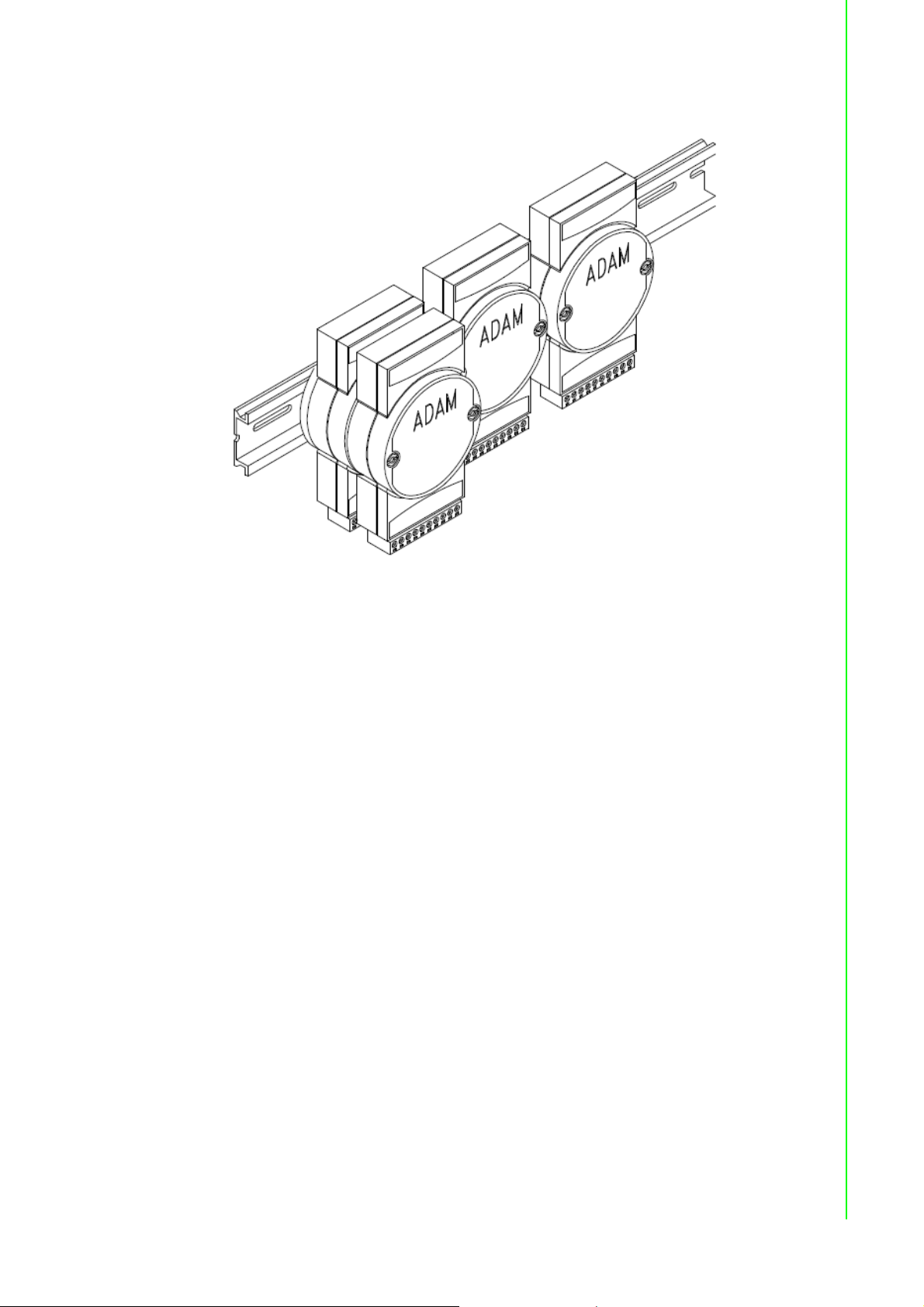
Panel/DIN Rail mounting
Chapter 1 Introduction
ADAM modules can be mounted on any panels, brackets, or DIN rails. They can also
be stacked together.
The RS-485 network, together with screw-terminal plug connectors, allows for system expansion, reconfiguration, and repair without disturbing field wiring.
Protection against the environment
Since all the configurations are controlled by software, the protection provided by the
packaging is very important. The plastic outer shell enhances resistance against corrosive materials, moisture and vibrations. ADAM modules’ low power requirements
help them to operate in temperatures from 0 to 70 ?, and in humidity from 0 to 95%
(non-condensing). They are compactly built using automated SMT technology.
Therefore, they can be implemented in water-tight and explosion-proof industrial
enclosures.
1.2 Applications
Remote data acquisition
Process monitoring
Industrial process control
Energy management
Supervisory control
Security systems
Laboratory automation
Building automation
Product testing
Direct digital control
3 ADAM-4000 Series User Manual
Page 18

ADAM-4000 Series User Manual 4
Page 19

Chapter 2
2 Installation Guideline
Page 20

This chapter provides guidelines to what is needed to set up and install an ADAM
network. A quick hookup scheme is provided that lets you configure modules before
they are installed in a network. To help you connect ADAM modules with sensor
inputs, several wiring examples are provided. At last, you will find a programming
example using the ADAM command set at the end of this chapter.
Be sure to plan the layout and configuration of your network carefully before you
start. Guidelines regarding layout are given in Appendix E: RS-485 Network.
2.1 System Requirements to Set up an ADAM
Network
The following list gives an overview of what is needed to setup,
install and configure an ADAM environment.
ADAM modules
A host computer, such as an IBM PC/AT compatible, that can output ASCII char-
acters with a RS-232C or RS-485 port.
Power supply for the ADAM modules (+10 to +30 VDC )
ADAM Series Utility software
ADAM Isolated RS-232/RS-485 Converter (optional)
RS-232/RS-485 ADAM Repeater (optional)
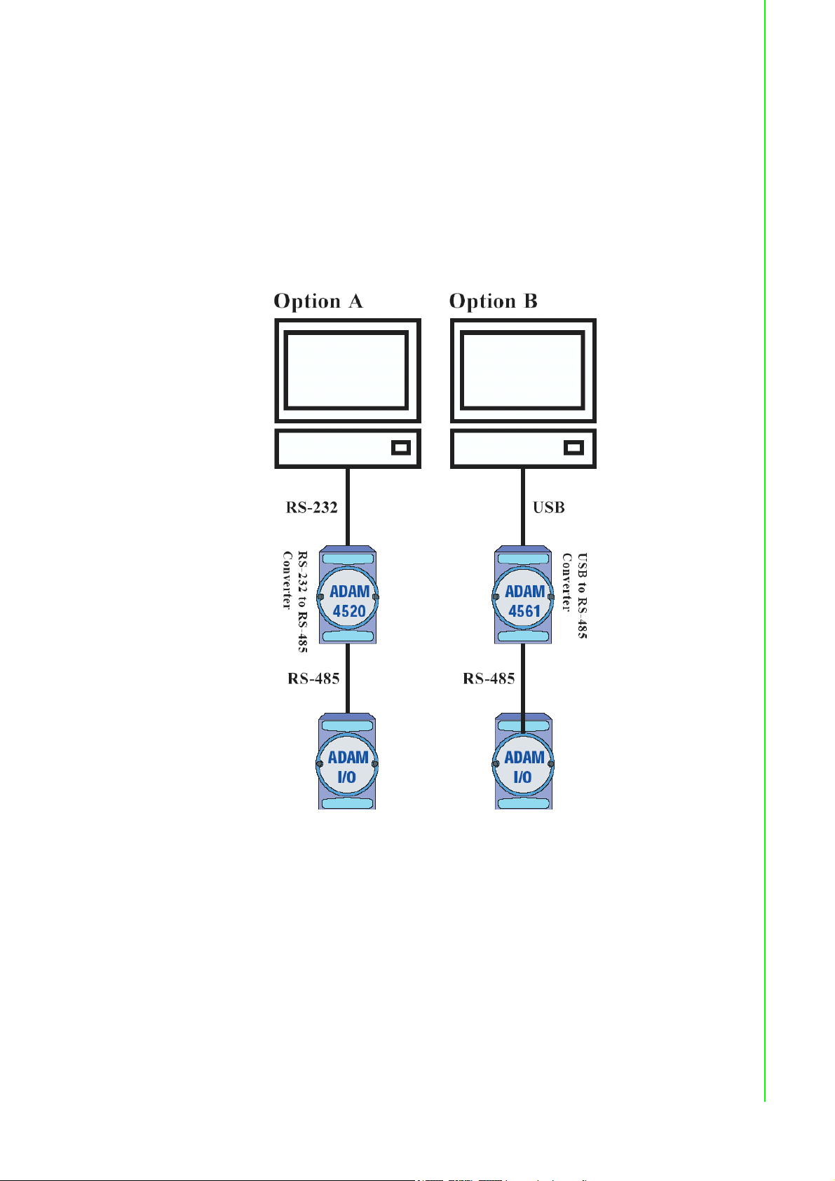
Host computer
Any computer or terminal that can output in ASCII format over either RS-232 or RS485 can be connected as the host computer. When only RS-232 is available, an
ADAM RS-232/RS-485 Converter is required to transform the host signals to the correct RS-485 protocol. The converter also provides opto-isolation and transformerbased isolation to protect your equipment.
Power supply
For the ease of use in industrial environments, the ADAM modules are designed to
accept industry standard +24 V
Operation is guaranteed when using any power supply between +10 and +30 V
Power ripples must be limited to 5 V peak to peak while the voltage in all cases must
be maintained between +10 and +30 V
enced at module connector. When modules are powered remotely, the effects of DC
voltage drops must be considered.
All modules use on-board switching regulators to sustain good efficiency over the 10
to 30 V input range; therefore, we can assume that the actual drawn current is
inversely proportional to the DC voltage.
The following example shows how to calculate the required current that a power supply should provide.
Assume that a +24 V
distance between modules and power supply is not significant enough to cause a DC
voltage drop. One ADAM-4011 module consumes a maximum of 1.2 Watts (W). The
total required power will equal to 5 x 1.2=6 W. A power supply of +24 VDC should
therefore be able to supply a minimal current of 6 / 24=0.25 Amps.
Small systems may be powered by using wall-mounted modular power supplies.
Also, when modules operate in long communication lines (>500 feet), it is often more
reliable to obtain power locally through modular power supplies. These inexpensive
units can be easily obtained from any electronic retail stores.
is used for five ADAM-4011 Analog Input Modules, and the
DC
, unregulated power.
DC
. All power supply specifications are refer-
DC
DC
.
ADAM-4000 Series User Manual 6
Page 21
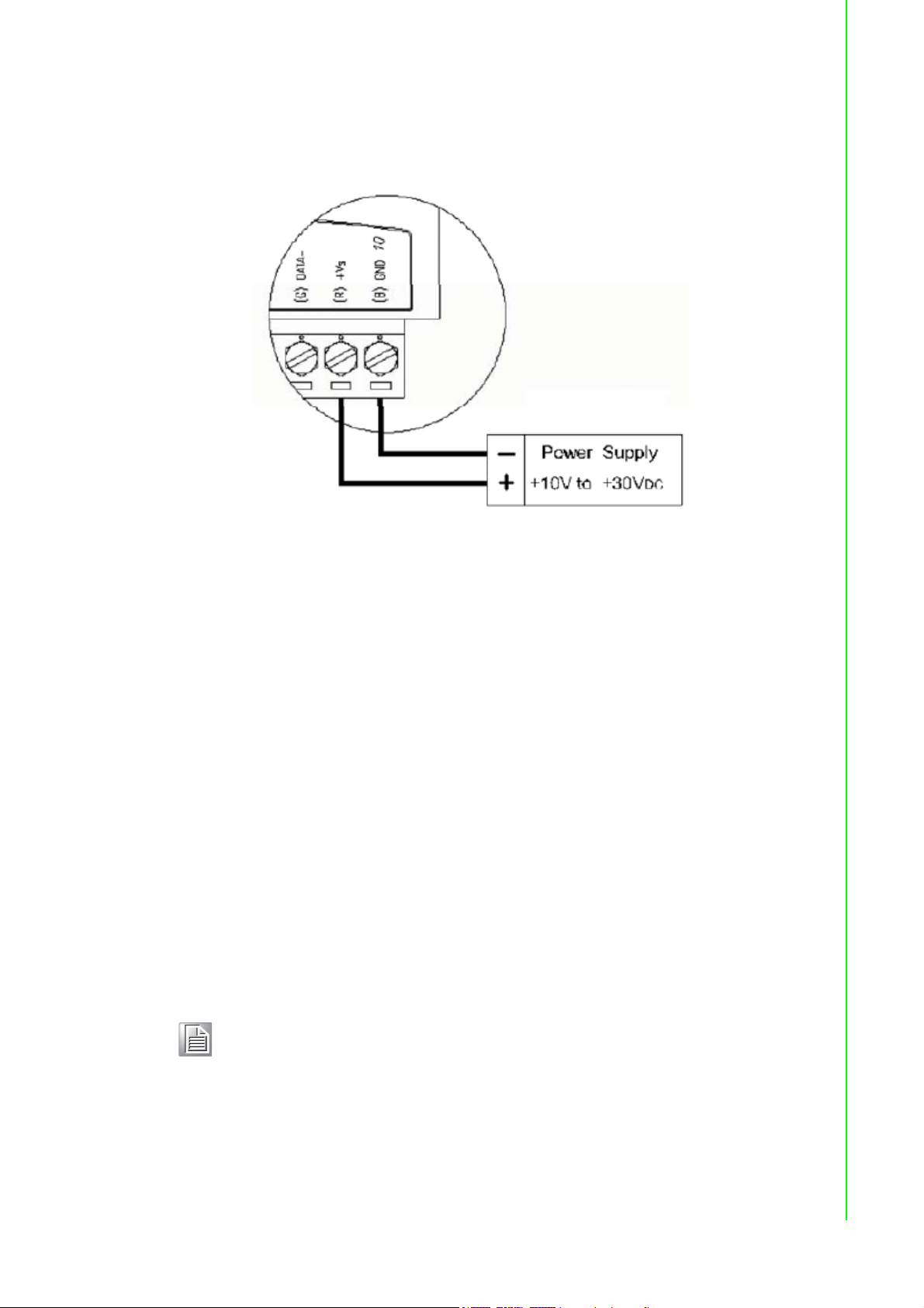
The power cables should be selected according to the length of the power lines and
the number of modules connected. When implementing a network with long cables,
the use of thicker wire is more suitable due to the limitation of DC voltage drop. Furthermore, long wires can also cause interference with communication wires.
Figure 2.1 Power Supply Connections
We advise the following standard colors (as indicated on the modules) for each
power line:
+Vs (R) Red
GND (B) Black
Chapter 2 Installation Guideline
Communication Wiring
We recommend the use of shielded-twisted-pair cable in the ADAM network for
reducing interference purpose, but the cable has to comply with the EIA RS-485
standard. Furthermore, only one set of twistedpair cable is required for transmitting
Data. We advise the following standard colors (as indicated on the modules) for each
the communication line:
DATA+ (Y) Yellow
DATA- (G) Green
ADAM Utility Software
A menu-driven utility program is provided for ADAM module configuration, monitoring
and, calibration. It also includes a terminal emulation program that lets you communicate through the ADAM command set. (See Appendix D, Utility Software and online
help)
Note! User can refer our help file to see more details for explanation of Utility
operation.
7 ADAM-4000 Series User Manual
Page 22

ADAM Communication Speed
In ADAM series, the baud rate can be configured from 1200 bps to 38.4 Kbps. However, the baud rate of all modules in an RS-485 network must be the same.
ADAM Isolated RS-232/RS485 Converter (optional): ADAM-452x
When the host computer or terminal only has a RS-232 port, an ADAM Isolated RS-
232/RS-485 Converter is required. Since this module is not addressable by the host,
the baud rate must be reset using a switch inside the module. The factory default setting is 9600 baud.
ADAM Repeater (optional): ADAM-451x
When communication lines exceed 4000 ft (1200 meter) or more than 32 ADAM
modules are connected, a repeater should be implemented. In a network, up to eight
Repeater modules can be connected allowing connection up to 255 ADAM modules.
As with the Converter module, the Repeater module is not addressable by the host
and the baud rate must be reset by changing the switch inside the module. The factory default setting is 9600 baud.
ADAM-4000 Series User Manual 8
Page 23
2.2 Basic Configuration and Hook-up
Before placing a module in an existing network, the module should be configured.
Though all modules are initially configured at the factory, it is recommended to check
if the baud rate is set correctly beforehand.
Default Factory Settings
Baud rate: 9600 Bit/sec.
Address: 01 (hexadecimal)
The basic hook-up for module configuration is shown below.
Chapter 2 Installation Guideline
Figure 2.2 Basic Hook-up of ADAM Module to Host Switches
9 ADAM-4000 Series User Manual
Page 24

The following items are required to configure a module: an ADAM converter module,
a personal computer with RS-232 port (baud rate set to 9600) and the ADAM utility
software.
Configuration with the ADAM Utility Software
The easiest way to configure the ADAM module is by using the ADAM utility software. It is a user friendly structured menu program that will guide you through every
step of the configuration. (See Appendix D, Utility Software)
Changing the protocol from ADAM ASCII to Modbus
Some ADAM-4000 modules support both ADAM ASCII and Modbus protocols, and
the factory default setting of these modules is ADAM ASCII protocol. If you would like
to configure the modules to Modbus protocol, please refer to Appendix H which
describes how to change the protocol in ADAM utility.
Configuration with the ADAM command set
ADAM modules can also be configured by issuing direct commands through a terminal emulation program that is part of the ADAM utility software. The following example will guide you through the setup of an analog input module. Assume an ADAM4011 Analog Input module still has its default settings (baud rate 9600 and address
01h), and you are being requested to send its default settings before any reconfiguration is made.
Note! An analog input module requires a maximum of 7 seconds to perform
auto calibration and ranging after reboot or start up.
During this time span, the module can not be addressed to perform any
other actions.
Example:
Make sure that the module is properly connected and turn on all the connected
devices. Then, start the terminal emulation program, and type in the following command:
$012(cr)
The command above requests the module with address 01 to send its configuration
status
!01050600
Module at address 01 responds that it is configured for an input range of +/-2.5 V,
baud rate of 9600, integration time of 50 ms (60 Hz).
The code also shows engineering units and no checksum checking or generation.
To change the configuration setting of the analog input module, the following command is issued:
%01070F0600(cr)
% = change configuration
01 = target module at address 00 to:
07 = change address to 07 hexadecimal
0F = set input range to Type K thermocouple
06 = set baud rate to 9600
00 = set integration time to 50 ms (60 Hz)
disable checksum
ADAM-4000 Series User Manual 10
Page 25

set data format to engineering units
(Please refer to Chapter 4, a full description of Command set syntax for an analog
input module)
When the module received the configuration command, it will respond with its new
address as shown below:
!07(cr)
Before giving more commands to the module, please wait for 7 seconds to let the
new configuration settings to take effect.
Note! All reconfiguration except for changing baud rate and checksum values
can be done dynamically, and the modules are not required to reset.
However, all the connected devices are required to reset by turning
power off and on after the baud rate or checksum values are changed.
The baud rate or checksum values should be the same for all the connected devices after the reconfiguration. See the next page for a strategy in changing baud rate and checksum of the network.
2.3 Baud Rate and Checksum
Chapter 2 Installation Guideline
ADAM modules contain EEPROMs to store configuration information and calibration
constants. The EEPROM replaces the conventional array of switches and pots that
are originally used for specifying baud rate, input and output range… etc.
Since there is no visual indication of a module’s configuration status, it is impossible
to know the baud rate, address and other settings just by looking at it. It might not be
possible to establish communications with a module whose baud rate and address
are unknown. To overcome this problem, most modules have an input terminal
labeled INIT*. Booting the module while connecting the INIT* terminal with the module’s GND terminal forces the configuration into a known state called the INIT* state.
Besides, some newer modules have INIT switch which you can set “Init” or “Normal”
(See Figure 2.4). If you set the switch to “Init”, then it becomes INIT* state.
INIT* state defaults:
Baud rate: 9600
Address: 00h
Checksum: disabled
Forcing the module in INIT* state does not change any parameters in the module’s
EEPROM. When the module is in the INIT* state with its INIT* and GND terminals
shorted, all configuration settings can be changed, and the module will respond to all
other commands normally.
Changing Baud rate and Checksum
Baud rate and checksum settings have several things in common:
They should be the same for all modules and host computer.
Their settings can only be changed by putting a module in the INIT* state.
Changed settings can only take effect after a module is rebooted
11 ADAM-4000 Series User Manual
Page 26
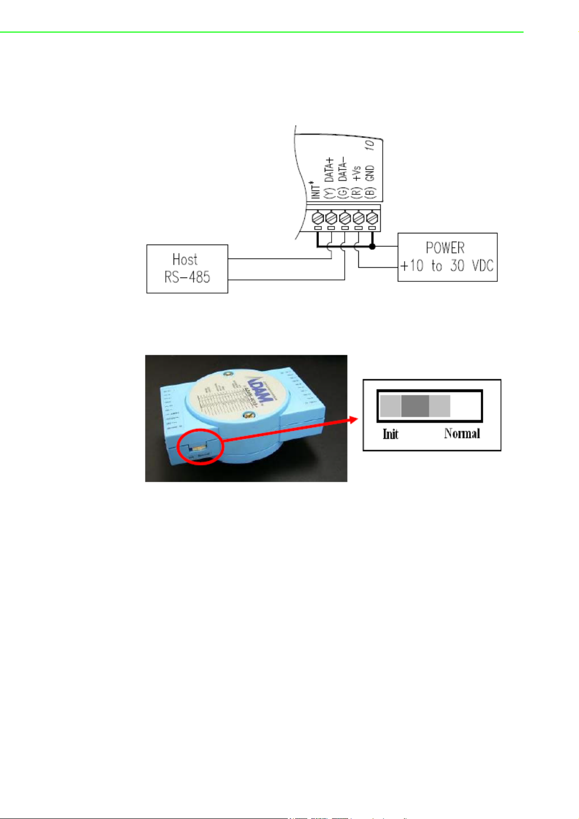
To alter baud rate or checksum settings, you must perform the following steps:
Power on all components except the ADAM Module.
• Power the ADAM module on while shorting the INIT* and GND terminals (See
Figure 2.3) or set the INIT switch to “Init” (See Figure 2-4)
Figure 2.3 Grounding the INIT* Terminal
Figure 2.4 Set INIT switch to “Init”
Configure the checksum status and/or the baud rate.
Switch the power OFF to the ADAM Module.
Remove the grounding of the INIT* terminal and turn on the module, or set the
INIT switch to “Normal”.
Check the settings (If the baud rate has changed, the settings on the host com-
puter should be changed accordingly).
ADAM-4000 Series User Manual 12
Page 27
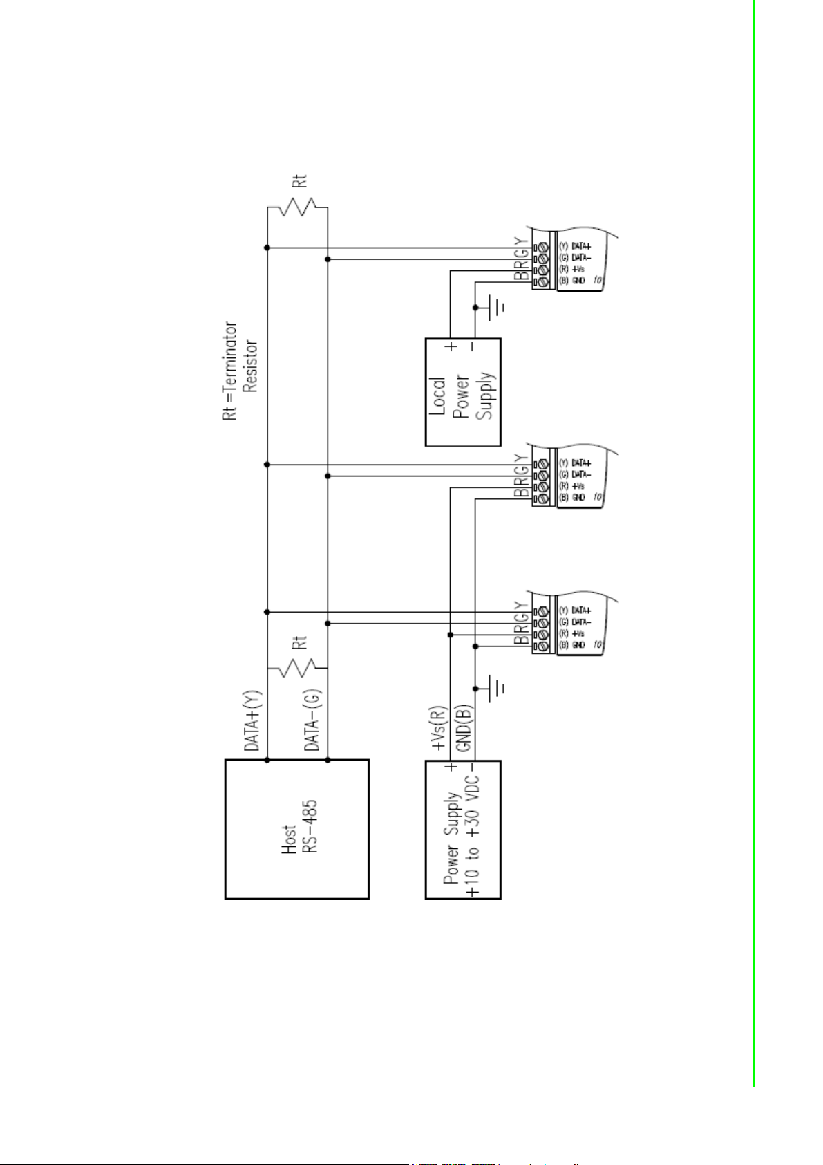
2.4 Multiple Module Hookup
The Figure below is an example of how ADAM modules are connected in a multiple
module network:
Chapter 2 Installation Guideline
Figure 2.5 Multi-module Connection
13 ADAM-4000 Series User Manual
Page 28
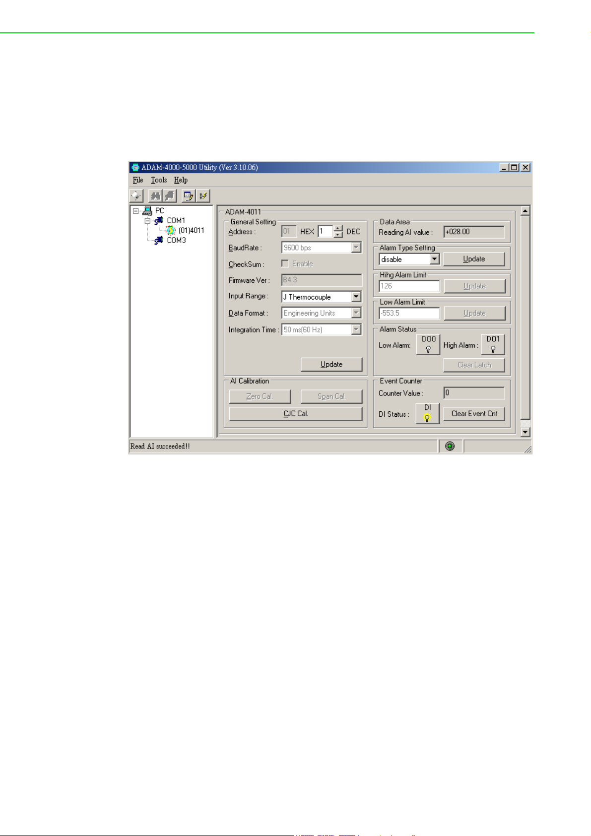
2.5 Programming Example
The following example is a simple program written in Visual Basic 6.0 that demonstrates how to get temperature reading which is stored in the address of 01H from
ADAM-4011 module.
1. Using ADAM Utility to check the settings as the following below:
“Address = 01H”, “Baud rate = 9600” and “Checksum = Disabled”.
ADAM-4000 Series User Manual 14
Page 29
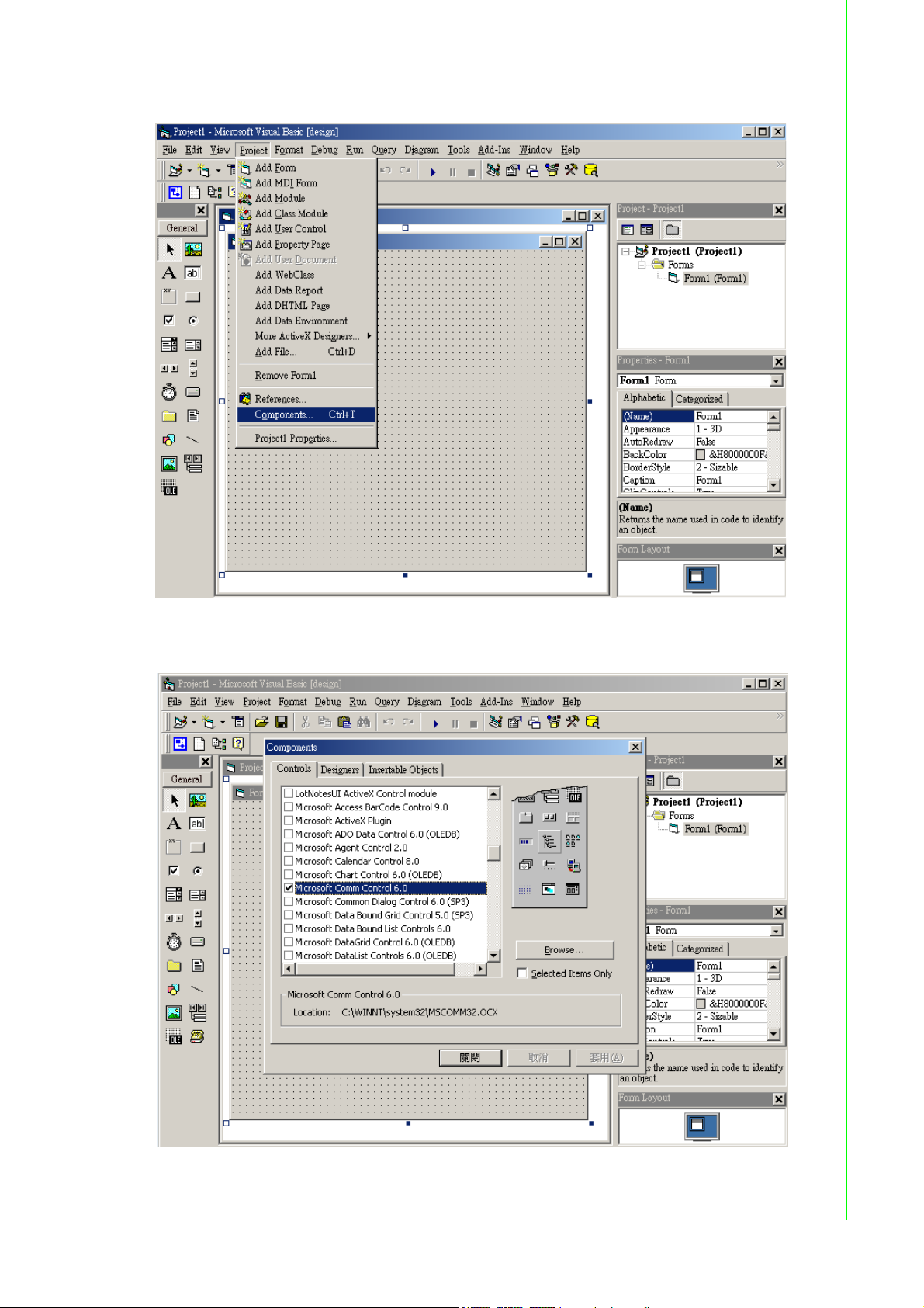
2. Run VB 6.0 and add a control via “Project\Component”.
Chapter 2 Installation Guideline
3. Select “Microsoft Comm Control”.
15 ADAM-4000 Series User Manual
Page 30
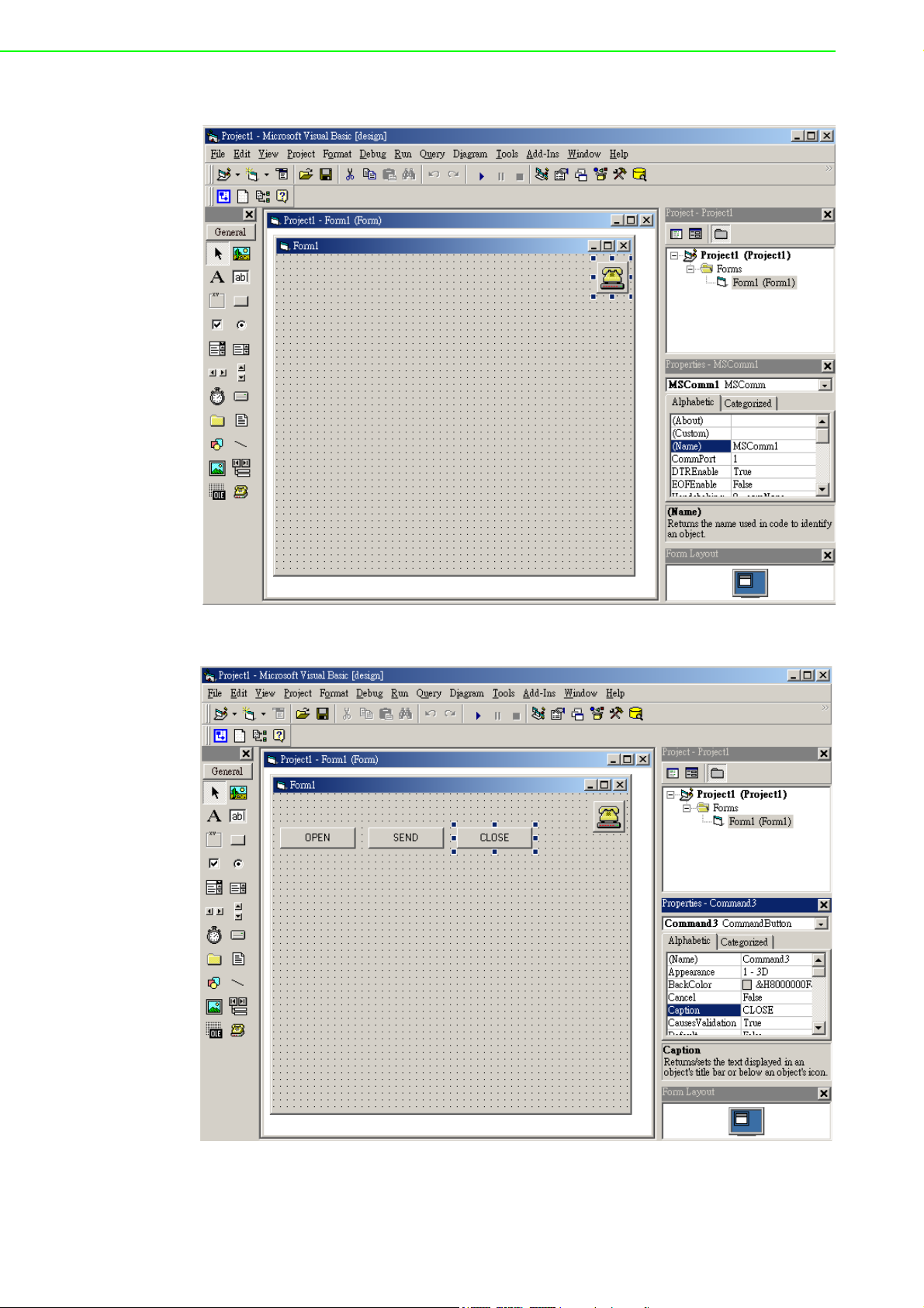
4. Add the Comm Control on the form.
5. Add three Command Buttons on the form as shown below.
ADAM-4000 Series User Manual 16
Page 31
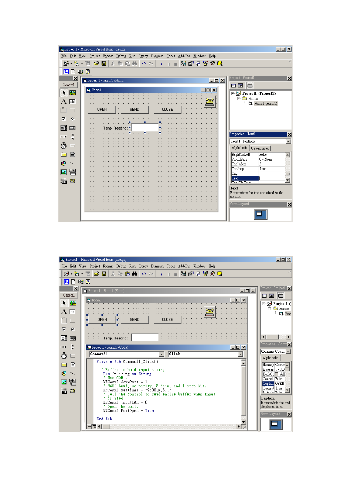
6. Add one Label and one Text on the form as shown below.
Chapter 2 Installation Guideline
7. Click OPEN Button and type in the following codes. The source codes are listed
at the end of this section.
17 ADAM-4000 Series User Manual
Page 32
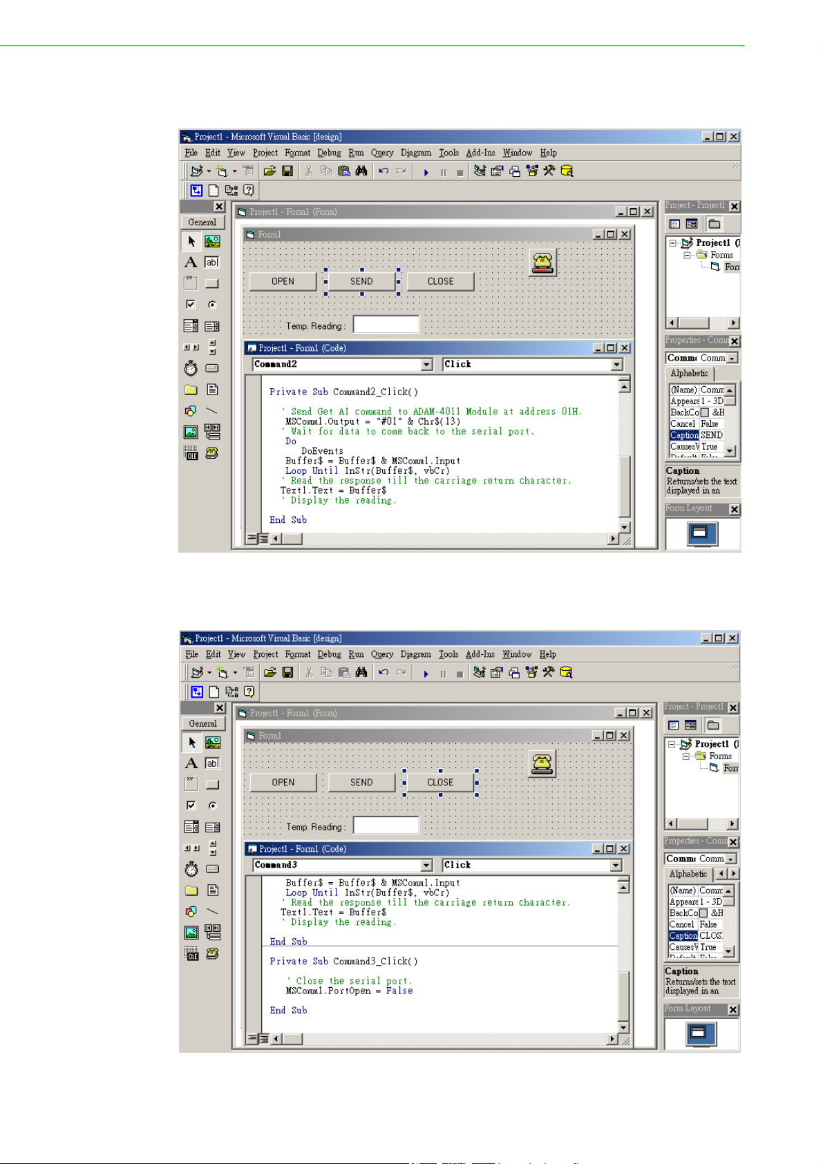
8. Click SEND Button and type in the following codes. The source codes are listed
at the end of this section.
9. Click CLOSE Button and type in the following codes. The source codes are
listed at the end of this section.
ADAM-4000 Series User Manual 18
Page 33
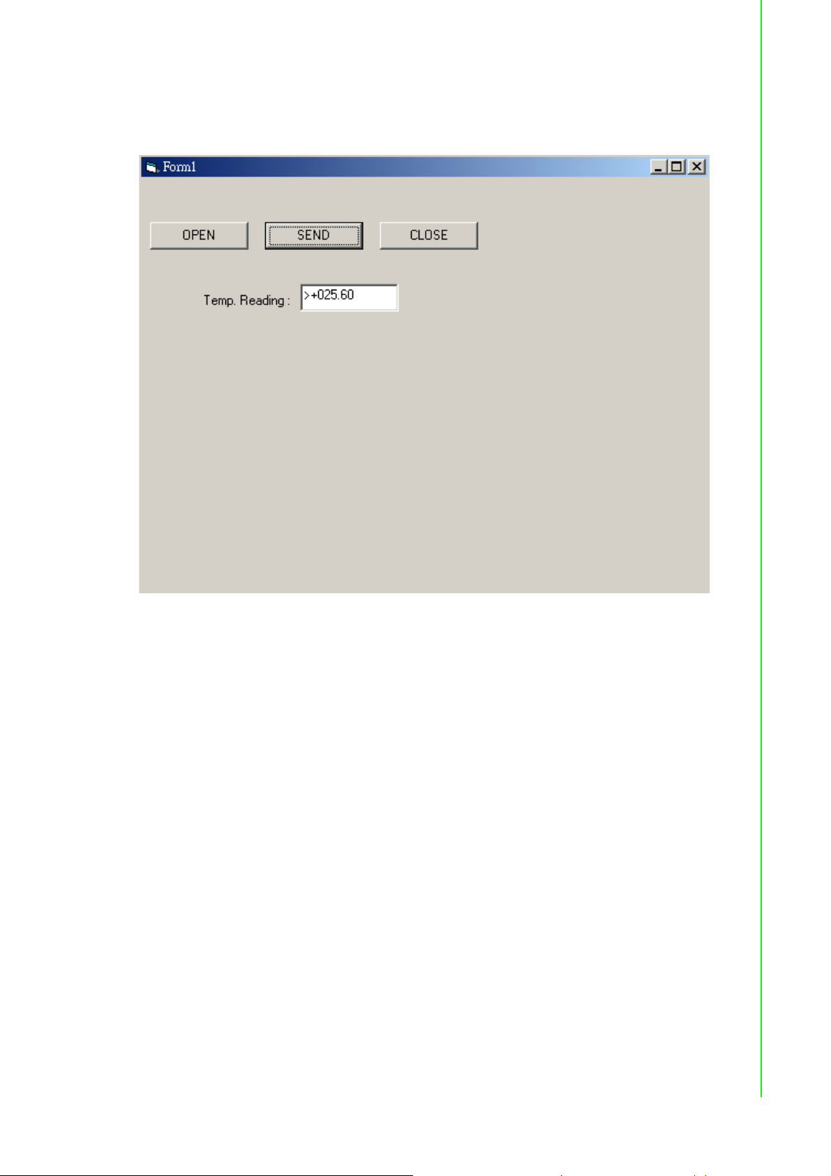
10. Run the Project Click OPEN to open COM1 Click SEND to send the Get
Temperature Reading Command. Now, you will find the reading the same as the
displayed format shown below.
Chapter 2 Installation Guideline
Program Source Codes:
OPEN Command Button:
Private Sub Command1_Click()
' Buffer to hold input string
Dim Instring As String
' Use COM1.
MSComm1.CommPort = 1
' 9600 baud, no parity, 8 data, and 1 stop bit.
MSComm1.Settings = "9600,N,8,1"
' Tell the control to read entire buffer when Input ' is used.
MSComm1.InputLen = 0
' Open the port.
MSComm1.PortOpen = True
End Sub
19 ADAM-4000 Series User Manual
Page 34

SEND Command Button:
Private Sub Command2_Click()
' Send Get AI command to ADAM-4011 Module at address 01H.
MSComm1.Output = "#01" & Chr$(13)
' Wait for data to come back to the serial port.
Do
DoEvents
Buffer$ = Buffer$ & MSComm1.Input
Loop Until InStr(Buffer$, vbCr)
' Read the response till the carriage return character.
Text1.Text = Buffer$
' Display the reading.
End Sub
CLOSE Command Button
Private Sub Command3_Click()
' Close the serial port.
MSComm1.PortOpen = False
End Sub
ADAM-4000 Series User Manual 20
Page 35

Chapter 3
3 I/O Modules
Page 36

3.1 The Common Specification of ADAM-4000 I/O
Series
Communication:
RS-485 (2-wire) to host
Speeds: 1200, 2400, 4800, 9600, 19200, 38400, 57600, 115200 bps (ADAM-
4080, ADAM-4080D only support up to 38400 bps)
Max. communication distance: 4000 feet (1.2 km)
Power and communication LED indicator
ASCII command/response protocol
Communication error checking with checksum
Asynchronous data format: 1 start bit, 8 data bits, 1 stop bit, no parity (N, 8, 1)
Up to 256 multidrop modules per serial port
Online module insertion and removal
Transient suppression on RS-485 communication lines
Power Requirement:
Unregulated +10 ~ +30 VDC
Protected against power reversal
Mechanical:
Case: ABS+PC with captive mounting hardware
Plug-in screw: Stripped length: 6.5 mm
Terminal block: #14 ~22 or #14~28 AWG
Environment
EMI: Meets FCC Class A or CE
Operating Temperature: -10 ~ 70° C (14 ~ 158° F)
Storage Temperature: -25 ~ 85° C (-13 ~ 185° F)
Humidity: 5 ~ 95%, non-condensing
3.2 ADAM-4011/4011D Thermocouple Input Modules
The ADAM-4011/4011D Thermocouple Input Modules use a microprocessor-controlled integrating A/D converter to convert sensor voltage, current or thermocouple
signal into digital data. The digital data is then translated into either two’s complement hexadecimal format or percentage of full-scale range (FSR) according to the
module’s configuration. When prompted by the host computer, the data is sent
through a standard RS-485 interface.
The ADAM-4011/4011D Thermocouple Input Modules offer signal conditioning, A/D
conversion, ranging, and RS-485 digital communication functions. They protect your
equipment from power surges at the ground terminal by providing opto-isolation of
the A/D input and transformer based isolation up to 3000 V
transformer-based isolation up to 500 V
DC
)
. (ADAM-4011 has
DC
ADAM-4000 Series User Manual 22
Page 37

Open Thermocouple Detection and Input Surge Protection (ADAM-4011D only)
The ADAM-4011D provides an open thermocouple detection function. Users can use
a simple command to detect whether the thermocouple is opened or closed. The
module also provides surge protection on its input channel. Internal high-speed transient suppressor on its input channel protects the module from dangerous spikes and
voltages.
Front Panel LED Indicator (ADAM-4011D only)
The 4½ digits LED display on the back of the ADAM-4011D lets you monitor the process readings right at their source. The module displays readings in a wide variety of
formats as well as high-low alarm messages. The ADAM-4011D offers flexibility, easy
installation, and direct availability of process data. For critical process monitoring, this
module is the ideal choice.
Digital Input/Output
The ADAM-4011/4011D Thermocouple Input Modules also contain two digital outputs
and one digital input. Outputs are open-collector transistor switches that may be controlled by the host computer. They can control solid-state relays, which may be used
to control heaters, pumps, and other electrical powered equipment. The digital inputs
may be read by the host computer and used to sense the state of a remote digital signal.
Chapter 3 I/O Modules
Event counting
The event counter is connected to the Digital Input channel and can be used to keep
track of the total amount of external low-speed pulses. Its accumulated maximal
count is 65535. The count will maintain at 65535 even if the actual number of events
exceeds 65535. The counter can be read or reset to zero by the host computer.
Since the Event counter’s data are not stored in EEPROM, the event counter is
cleared and set to zero after every reset or start up of the analog input module.
Alarm signaling
Analog input modules include High and Low alarm functions. High and Low alarm
limits may be downloaded into the module’s EEPROM by the host computer.
The alarm functions can be enabled or disabled remotely. When the alarm function is
enabled, both Digital Output channels are used to indicate the High and Low alarm
state. Digital Output channel 1 (DO1) equals to High alarm state, and Digital Output
channel 0 (DO0) equals to Low alarm state. The High and Low alarm states can be
read at any time by the host computer.
Every A/D conversion will be followed by a comparison with the High and Low limit.
When the input value exceeds one of these limits, the High or Low alarm state is set
to ON.
There are two alarm mode options, Momentary and Latching. If the alarm is in Latching mode, the alarm will stay on even if the input value returns within the limits. An
alarm in Latching mode can be turned OFF by giving a Clear Alarm command from
the host computer. A Latching alarm is cleared by the module when the opposite
alarm is set. When
the module receives a value that is lower than the Low alarm limit, it will clear the
High alarm and turn the Low alarm ON.
When the alarm is in Momentary mode, the alarm will be turned OFF as soon as the
input value returns within the limits.
23 ADAM-4000 Series User Manual
Page 38

The arrangement of coupling High and Low alarm states with Digital Output lines may
be utilized to build ON/OFF controllers that
can operate without the involvement of host computer.
Function Description for the ADAM-4011 Thermocouple Input Module
To provide a better understanding of the ADAM module functions, the following is a
description of the module ADAM-4011 with the most extensive set of functions.
All analog input data first flow through the PGA (programmable gain amplifier). The
amplifier can vary its gain from 1 to 128. The PGA then automatically adjusts the signal to a range from -2.5 V to +2.5 V.
This ensures an optimal input voltage and resolution for the A/D converter.
The A/D conversion is supervised by the microprocessor that holds the calibration
software. Two kinds of calibrations, Auto Zero and Auto Span calibrations, take place
automatically in startup or reset. Normal calibration is used to adjust the signal
according to calibration parameters defined by the user.
The digital 10 Hz filter provides a steady state output by using the unction.
Before the data enter the microprocessor, they pass through an optical isolation
device which prevents the chance of circuit damaging caused by power surges from
the ground terminal.
The microprocessor has six basic functions:
- Linearization of T/C (Thermocouple)
- Communication software and command set
- Calibration software
- Alarm monitoring
- Event counting
- Management of the EEPROM device that holds the system parameters
- Data transformation
After data have been transformed to the right data format, they are being passed on
to the RS-485 output port.
If an input value exceeds the High alarm setting or falls below the Low alarm setting,
a flag is set in one of the Digital Output channels.
Finally, the on-board switching regulator accepts voltage between +10 and +30 V
and it has an isolation value of 500 V
to protect your equipment from damages
DC
DC
caused by power surges.
,
ADAM-4000 Series User Manual 24
Page 39
3.2.1 ADAM-4011D Thermocouple Input Module
Chapter 3 I/O Modules
Figure 3.1 ADAM-4011 Thermocouple Input Module
Accepts:
- J, K, T, E, R, S and B thermocouples
- Millivolt inputs: ±15 mV, ±50 mV, ±100 mV and ±500 mV
- Volt inputs: ±1 V and ±2.5 V
- Current input: ±20 mA (Requires a 125 resistor)
Two digital output channels and one digital input channel are provided.
Depending on the module’s configuration setting, it can forward the data to the host
computer in one of the following formats:
- Engineering units (°C, mV, V, or mA)
- Percent of full-scale range (FSR)
- Two’s complement hexadecimal
25 ADAM-4000 Series User Manual
Page 40
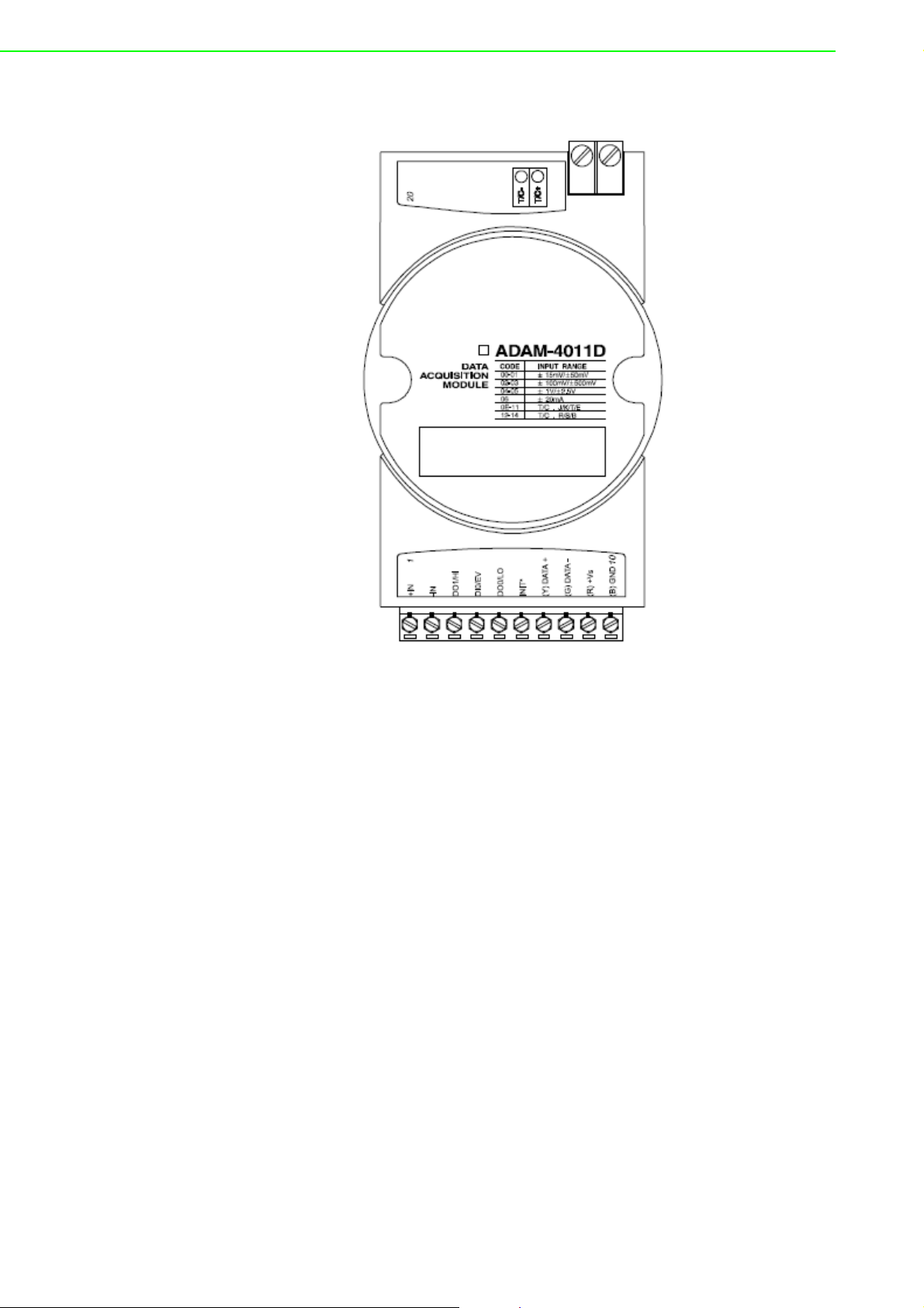
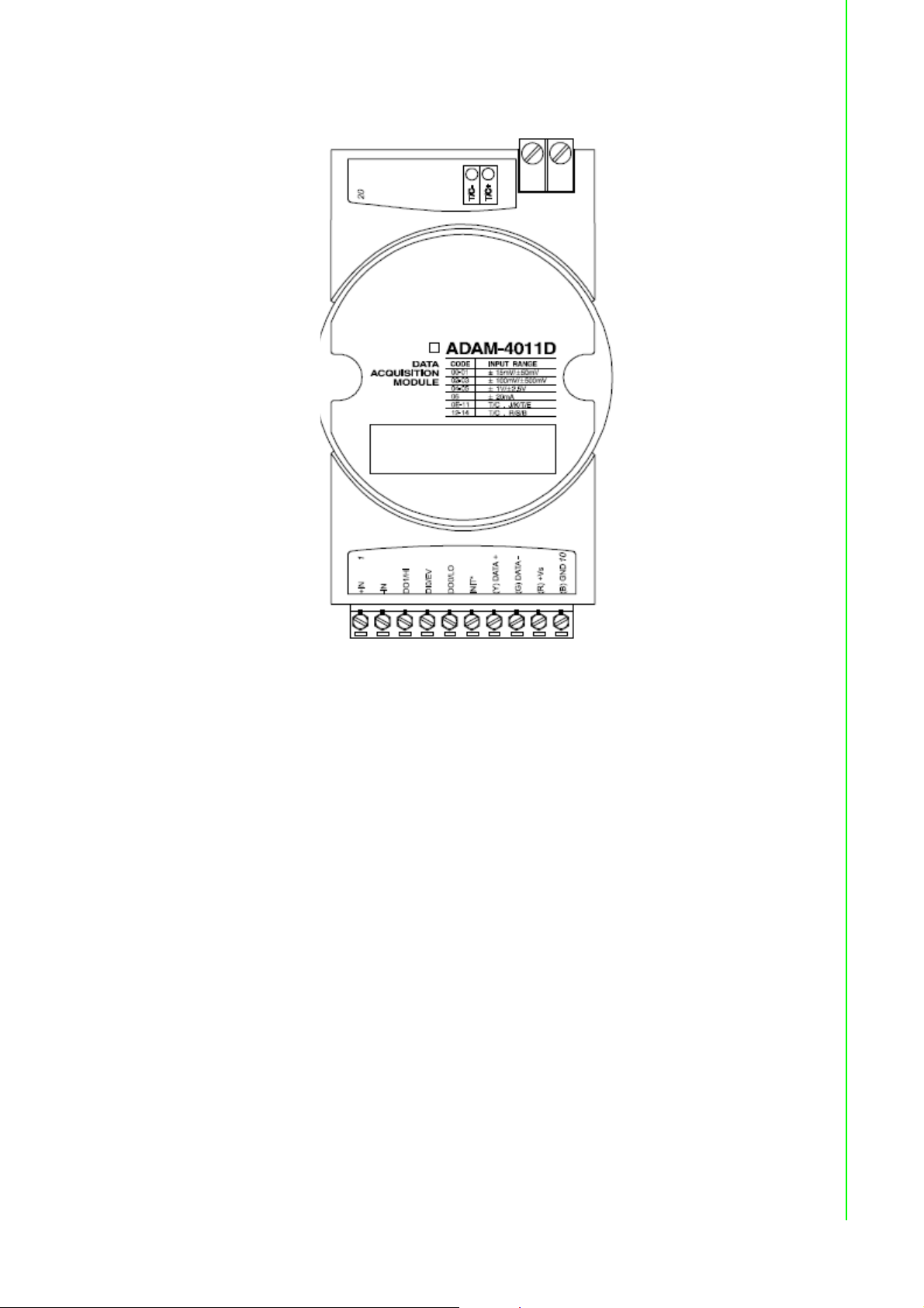
3.2.2 ADAM-4011D Thermocouple Input Module
Figure 3.2 ADAM-4011D Thermocouple Input Module with LED Display
Accepts:
- J, K, T, E, R, S and B thermocouples
- Millivolt inputs: ±15 mV, ±50 mV, ±100 mV and ±500 mV
- Volt inputs: ±1 V and ±2.5 V
- Current input: ±20 mA (Requires a 125 resistor)
Two digital output channels and one digital input channel are provided.
Depending on the module’s configuration setting, it can forward the data to the host
computer in one of the following formats:
- Engineering units (oC, mV, V, or mA)
- Percent of full-scale range (FSR)
- Two’s complement hexadecimal
ADAM-4000 Series User Manual 26
Page 41
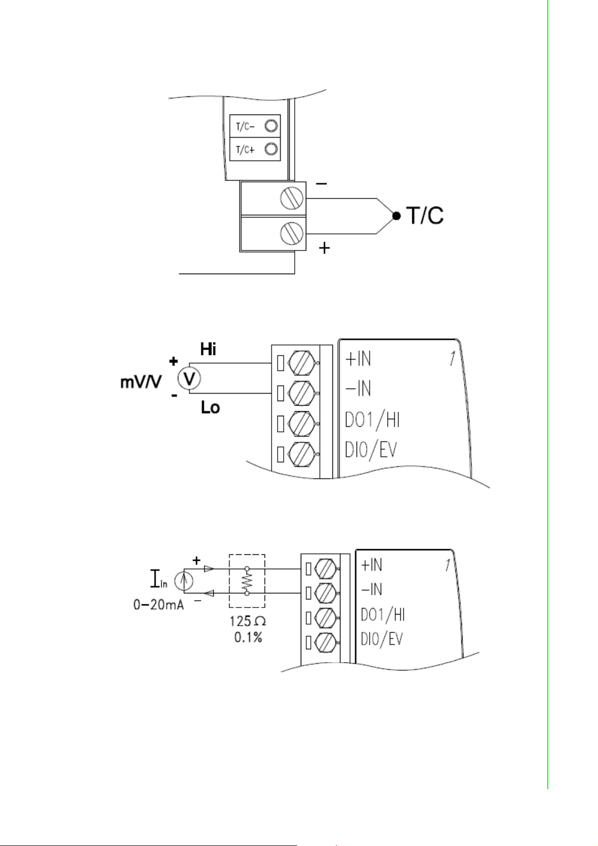
3.2.3 Application Wiring
Figure 3.3 ADAM-4011/4011D Thermocouple Input Wiring Diagram
Chapter 3 I/O Modules
Figure 3.4 ADAM-4011/4011D Millivolt and Volt Input Wiring Diagram
Figure 3.5 ADAM-4011/4011D Process Current Input Wiring Diagram
27 ADAM-4000 Series User Manual
Page 42

Figure 3.6 ADAM-4011/4011D Digital Output Wiring Diagram Used with SSR (HI-
LO alarm)
Figure 3.7 ADAM-4011/4011D Digital Input Wiring Diagram Used with TTL
Figure 3.8 ADAM-4011/4011D Digital Input Wiring Diagram Used with Dry
contact
ADAM-4000 Series User Manual 28
Page 43

3.3 ADAM-4012 Analog Input Module
The ADAM-4012 Analog Input Modules use a microprocessorcontrolled integrating
A/D converter to convert sensor voltage or current signals into digital data. The digital
data are then translated into either two’s complement hexadecimal format or percentage of full-scale range (FSR) according to the module’s configuration. When
prompted by the host computer, the data are sent through a standard RS-485 interface.
The ADAM-4012 Analog Input Modules offer signal conditioning, A/D conversion,
ranging, and RS-485 digital communication functions. They protect your equipment
from power surges at the ground terminal by providing opto-isolation of the A/D input
and up to 3000 V
Digital Inputs/Outputs
The ADAM-4012 also contains two digital outputs and one digital input. Outputs are
open-collector transistor switches that may be controlled by the host computer. They
can control solid-state relays, which can be applied to heaters, pumps, and other
electrical powered equipment. The digital inputs may be read by the host computer
and used to sense the state of a remote digital signal.
Event counting
The event counter is connected to the Digital Input channel and can be used to keep
track of the total amount of external low-speed pulses.
Its accumulated maximal count is 65535. The number 65535 is held even if the actual
number of events exceeds 65535. The counter can be read or reset to zero by the
host computer.
Since the Event counter’s data are not stored in EEPROM, the event counter is
cleared and set to zero after every reset or start up of the analog input module.
transformer based isolation.
DC
Chapter 3 I/O Modules
Alarm signaling
Analog input modules include High and Low alarm functions. High and Low alarm
limits may be downloaded into the module’s EEPROM by the host computer.
The alarm functions can be enabled or disabled remotely. When the alarm function is
enabled, both Digital Output channels are used to indicate the High and Low alarm
states. Digital Output channel 1 (DO1) equals to High alarm state, and Digital Output
channel 0 (DO0) equals to Low alarm state. The High and Low alarm states can be
read at any time by the host computer.
Every A/D conversion will be followed by a comparison with the High and Low limit.
When the input value exceeds one of these limits, the High or Low alarm state is set
to ON.
There are two alarm mode options, Momentary and Latching.
If the alarm is in Latching mode, the alarm will stay on even when the input value
returns within the limits. It can also be turned OFF by issuing a Clear Alarm command from the host computer. A Latching alarm is cleared by the module when the
opposite alarm is set.
When the module receives a value that is lower than the Low alarm limit, it will clear
the High alarm and turn the Low alarm ON.
When the alarm is in Momentary mode, the alarm will be turned OFF as soon as the
input value returns within the limits.
29 ADAM-4000 Series User Manual
Page 44

The arrangement of coupling High and Low alarm states with Digital Output lines may
be utilized to build ON/OFF controllers that can operate without involving the host
computer.
3.3.1 ADAM-4012 Analog Input Module
Figure 3.9 ADAM-4012 Analog Input Module
Accepts:
- Millivolt inputs ± 150 mV and ±500 mV
- Volt inputs: ±1 V, ±5 V and ±10 V
- Current input: ±20 mA (requires a 125 resistor)
Two digital output channels and one digital input channel are provided.
Depending on the module's configuration setting, it can forward the data to the host
computer in one of the following formats:
- Engineering units (mV, V, or mA)
- Percent of full-scale range (FSR)
- Two’s complement hexadecimal
ADAM-4000 Series User Manual 30
Page 45

3.3.2 Application Wiring
Figure 3.10 ADAM-4012 Millivolt and Volt Input Wiring Diagram
Chapter 3 I/O Modules
Figure 3.11 ADAM-4012 Process Current Input Wiring Diagram
Figure 3.12 ADAM-4012 Digital Output Wiring Diagram Used with SSR (HI-LO
alarm)
31 ADAM-4000 Series User Manual
Page 46

Figure 3.13 ADAM-4012 Digital Input Wiring Diagram Used with TTL
Figure 3.14 ADAM-4012 Digital Input Wiring Diagram Used with Dry contact
ADAM-4000 Series User Manual 32
Page 47

3.4 ADAM-4013 RTD Module
The ADAM-4013 RTD Input Module supports one Pt or Ni RTD input channel for temperature measurement. This module can accept RTD sensors with two, three, or four
wires. The module offers signal conditioning, A/D conversion, ranging, and RS-485
digital communication functions. It protects your equipment from power surges at the
ground terminal by providing opto-isolation of the A/D input and up to 3000 VDC
transformer based isolation.
Chapter 3 I/O Modules
Figure 3.15 ADAM-4013 RTD Input Module
Accepts:
- Input from platinum and nickel RTDs
Depending on the module’s configuration setting, it can forward the data to the host
computer in one of the following formats:
- Engineering units (°C)
- Percent of full-scale range (FSR)
- Two’s complement hexadecimal
33 ADAM-4000 Series User Manual
Page 48
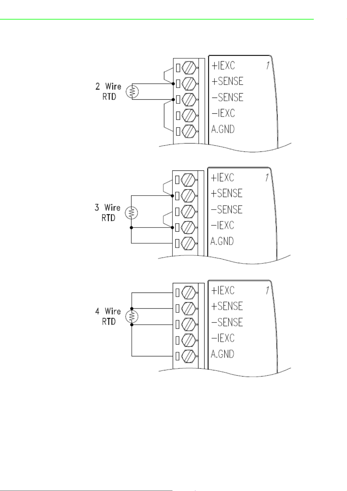
3.4.1 Application Wiring
Figure 3.16 ADAM-4013 RTD Inputs Wiring Diagram
ADAM-4000 Series User Manual 34
Page 49

3.5 ADAM-4015 6-channel RTD Input Module
A RTD module is popularly used for temperature measurement. Unlike the traditional
design, the ADAM-4015 RTD Input Module provides six RTD input channels for different types of RTD signal like as Pt, Ni, Balco. It is an effective solution in industrial
& building automation. Normally, broken external wire will lead to an inaccurate current value; however, the ADAM-4015 provides a broken wire detecting function.
Therefore, users can easily fix the broken wire problems. This module can accept
RTD sensors that have two or three wires. After the V2.04 of ADAM-4015, ADAM4015 can support the “BA1 -200~600°C”.
Please be noted that the pin 26 is defined as GND and it’s reserved.
Chapter 3 I/O Modules
Figure 3.17 ADAM-4015 6-channel RTD Input Module
35 ADAM-4000 Series User Manual
Page 50
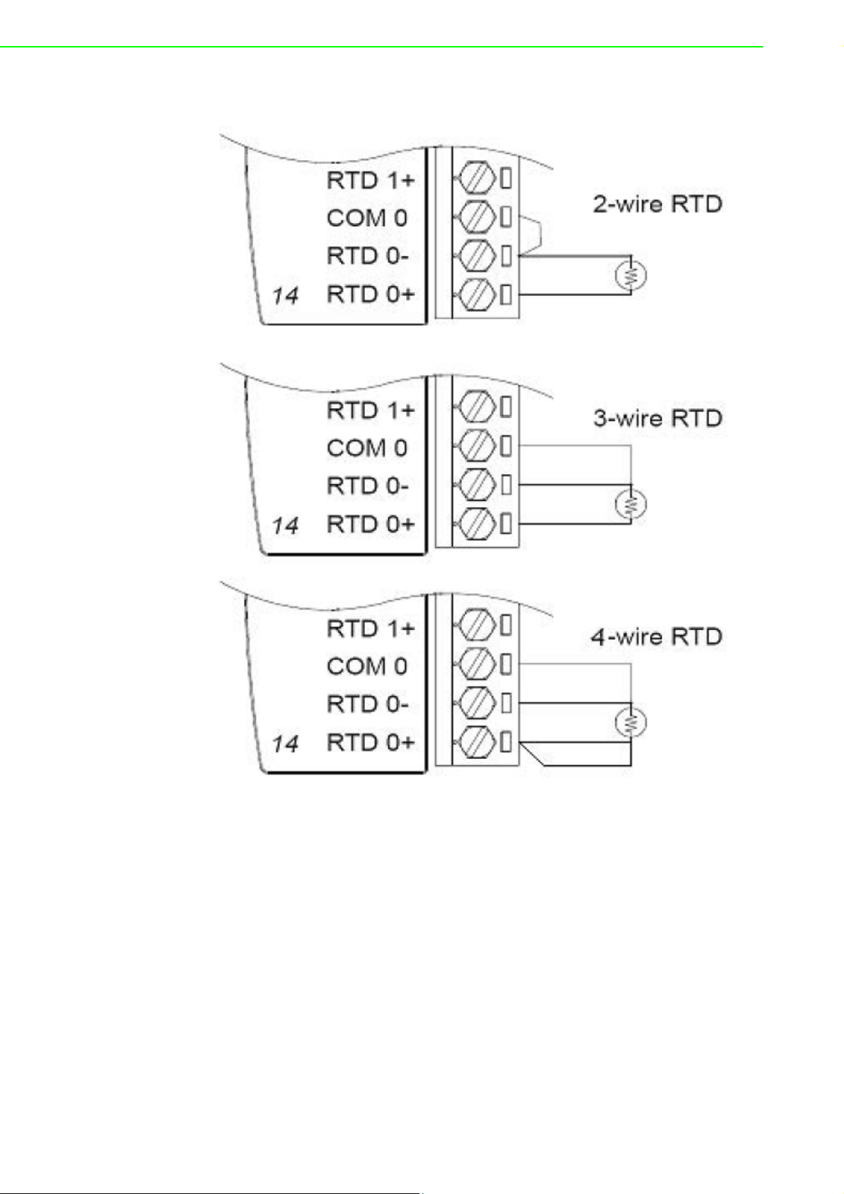
3.5.1 Application Wiring
Figure 3.18 ADAM-4015 RTD Input Module Wiring Diagram
ADAM-4000 Series User Manual 36
Page 51

3.5.2 Technical specification of ADAM-4015
Table 3.1: Technical Specification of ADAM-4015
Channel Number 6 differential
Support Protocol ADAM ASCII and MODBUS/RTU
Input Type Pt100, Pt1000, BALCO500, Ni
Input Connections 2 or 3 wires
Wire Burnout Detection Yes
Input Type and Temper-
ature Range
Isolation Voltage 3000 V
Sampling Rate 10 sample/second (total)
Input Impedance 10 M
Resolution 16-bit
Accuracy ±0.1% or better
CMR@50/60Hz 120 dB
NMR@50/60Hz 100 dB
Span Drift ± 25 ppm/°C
Zero Drift ± 3 V/°C
Watchdog Timer System (1.6 second) and Communication
Power Input +10~+30 V
Power Consumption 1.2 W @ 24V
Pt100: -50 to 150° C
0 to 100° C
0 to 200° C
0 to 400° C
-200 to 200° C
Pt1000: -40 to 160° C
Balco500: -30 to 120° C
Ni 50 RTD: -80 to 100° C
Ni 508 RTD: 0 to 100° C
DC
(non-regulated)
DC
DC
Chapter 3 I/O Modules
37 ADAM-4000 Series User Manual
Page 52
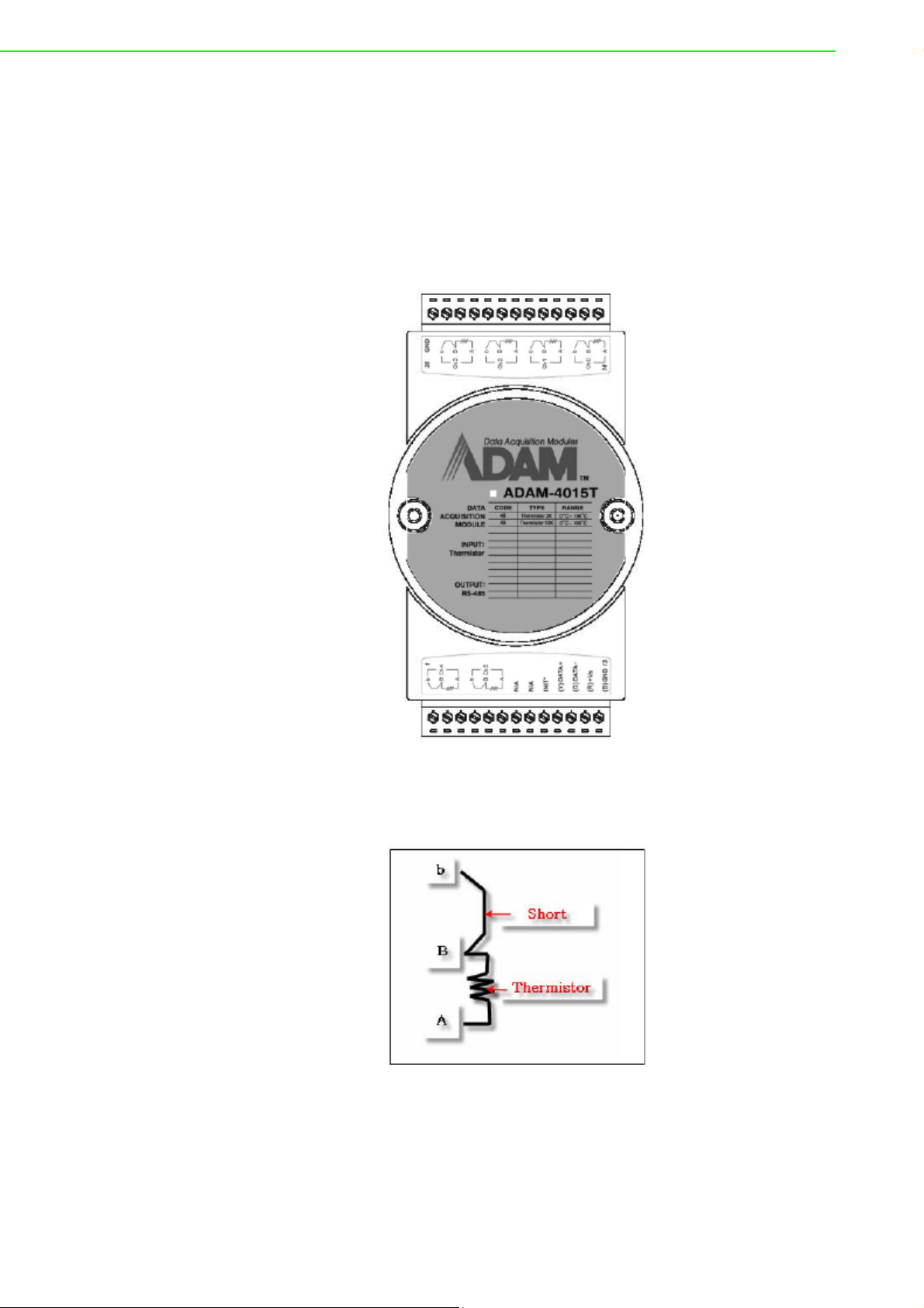
3.6 ADAM-4015T 6-channel Thermistor Input
Module
A Thermistor Module is popularly used for temperature measurement. Unlike the traditional design, the ADAM-4015T provides six thermistor input channels for thermistor signal. It is an effective solution in industrial & building automation. Normally,
broken external wires will lead to an inaccurate current value. The ADAM-4015T provides a broken wire detecting function, so users can easily fix the problems.
Figure 3.19 ADAM-4015T 6-channel Thermistor Input Module
3.6.1 Application Wiring
Figure 3.20 ADAM-4015T Thermistor Input Module Wiring Diagram
ADAM-4000 Series User Manual 38
Page 53

3.6.2 Technical Specification of ADAM-4015T
Table 3.2: Technical Specification of ADAM-4015T
Channel Number 6 differential
Support Protocol ADAM ASCII and MODBUS/RTU
Input Type Thermistor
Input Connections 2 or 3 wires
Wire Burnout Detection Yes
Input Type and
Temperature Range
Isolation Voltage 3000 V
Sampling Rate 10 sample/second (total)
Input Impedance 10 M
Resolution 16-bit
Accuracy ±0.1% or better
CMR@50/60Hz 120 dB
NMR@50/60Hz 100 dB
Span Drift ± 25 ppm/°C
Zero Drift ± 3 V/°C
Watchdog Timer System (1.6 second) and Communication
Power Input +10~+30 V
Power Consumption 1.2 W @ 24V
Thermistor 3k 0~100? (9.796K ohm ~ 203.8 ohm)
Thermistor 10k 0~100?(29.49K ohm ~ 816.8 ohm)
DC
(non-regulated)
DC
DC
Chapter 3 I/O Modules
39 ADAM-4000 Series User Manual
Page 54

3.7 ADAM-4016 Analog Input/Output Module
A strain gauge input module uses a microprocessor-controlled integrating A/D converter to convert sensor voltage or current signals into digital data for load cell and
stress measurement. The digital data are then translated into either, two’s complement hexadecimal format or percentage of full-scale range (FSR) according to the
module’s configuration. When prompted by the host computer, the data are sent
through a standard RS-485 interface.
The strain gauge input module offers signal conditioning, A/D conversion, ranging,
and RS-485 digital communication functions.
They protect your equipment from power surges at the ground terminal by providing
opto-isolation of the A/D input and up to 3000 VDC transformer based isolation.
Excitation Voltage Output
A strain gauge input module can supply single channel voltage output for excitation.
The module receives digital input from the host computer, and the format of the data
is engineering units. It then uses its microprocessor-controlled D/A converter to convert the digital data into output signals.
Strain gauge input modules protect your equipment from power surges at the ground
terminal by providing opto-isolation of the D/A output and up to 3000 VDC transformer-based isolation.
Digital Outputs
A strain gauge input module also contains four digital outputs. Outputs are open-collector transistor switches that may be controlled by the host computer. They can control solid-state relays which can be applied to heaters, pumps, and other electrical
controlled equipments.
Alarm signaling
Strain Gauge input modules include High and Low alarm functions. High and Low
alarm limits may be downloaded into the module’s EEPROM by the host computer.
The alarm functions can be enabled or disabled remotely. When the alarm function is
enabled, both Digital Output channels are used to indicate the High and Low alarm
states. Digital Output channel 1 (DO1) equals to High alarm state and Digital Output
channel 0 (DO0) equals to Low alarm state. The High and Low alarm state can be
read at any time by the host computer.
Every A/D conversion will be followed by a comparison with the High and Low limits.
When the input value exceeds one of these limits, the High or Low alarm state is set
to ON.
There are two alarm mode options, Momentary and Latching. If the alarm is in Latching mode, the alarm will stay on even when the input value returns within limits. An
alarm in Latching mode can be turned OFF by issuing a Clear Alarm command from
the host computer. A Latching alarm is cleared by the module when the opposite
alarm is set.
When the module receives a value that is lower than the Low alarm limit, it will clear
the High alarm and turn the Low alarm ON.
When the alarm is in Momentary mode, the alarm will be turned OFF as soon as the
input value returns to within limits.
The arrangement of coupling High and Low alarm states with Digital Output lines may
be utilized to build ON/OFF controllers that can operate without the host computer
involvement.
ADAM-4000 Series User Manual 40
Page 55
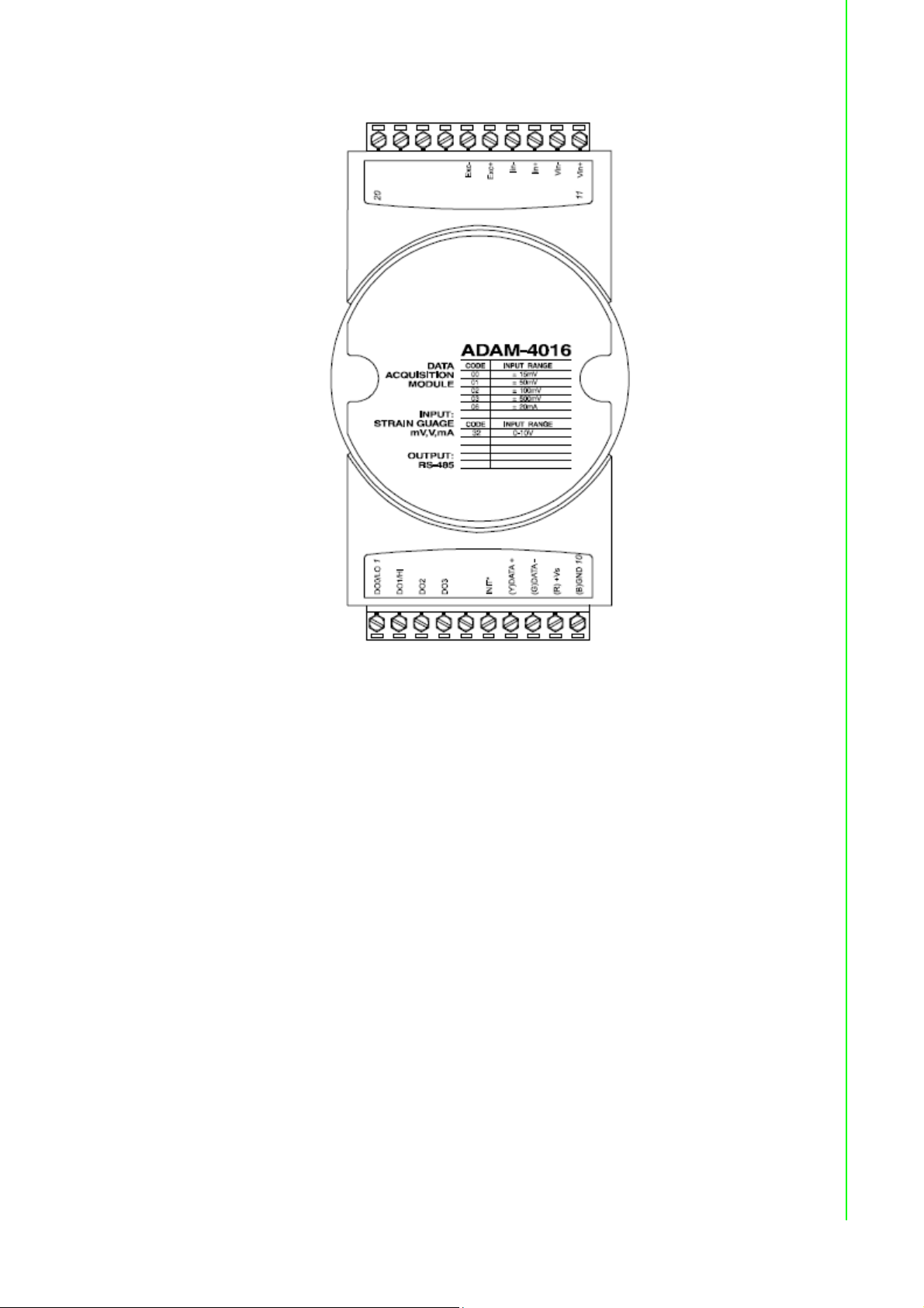
Chapter 3 I/O Modules
Figure 3.21 ADAM-4016 Analog Input/Output Module
Accepts:
- Millivolt inputs: ±15 mV, ±50 mV, ±100 mV, ±500 mV
- Current input: ±20 mA
Excitation voltage output: 0 ~ 10 V
Four digital output channels are provided.
Depending on the module’s configuration setting, it can forward the data to the host
computer in one of the following formats:
- Engineering units (mV or mA)
- Percent of full-scale range (FSR)
- Two’s complement hexadecimal
41 ADAM-4000 Series User Manual
Page 56

3.7.1 Application Wiring
Figure 3.22 ADAM-4016 Strain Gauge Voltage Input Wiring Diagram
Figure 3.23 ADAM-4016 Strain Gauge Current Input Wiring Diagram
Figure 3.24 ADAM-4016 Digital Output Wiring Diagram Used with SSR
ADAM-4000 Series User Manual 42
Page 57

3.8 ADAM-4017/4017+/4018/4018M/4018+ 8-channel
Analog Input Modules
3.8.1 ADAM-4017/4018 8-channel Analog Input Module
The ADAM-4017/4018 is a 16-bit, 8-channel analog input module that provides programmable input ranges on all channels. This module is an extremely cost-effective
solution for industrial measurement and monitoring applications. Its opto-isolated
inputs provide 3000 VDC of isolation between the analog input and the module, and
protect the module and peripherals from damaging due to high input-line voltages.
The ADAM-4017/4018 offers signal conditioning, A/D conversion, ranging and RS485 digital communication functions. The module protects your equipment from
power surges at the ground terminal by providing opto-isolation of A/D input and up
to 3000 VDC transformer based isolation.
The ADAM-4017/4018 uses a 16-bit microprocessor-controlled sigma-delta A/D converter to convert sensor voltage or current into digital data. The digital data are then
translated into engineering units.
When prompted by the host computer, the module sends the data to the host through
a standard RS-485 interface.
3.8.2 ADAM-4018M 8-channel Analog Input Data logger
Chapter 3 I/O Modules
The ADAM-4018M is a 16-bit, 8-channel analog input data logger featuring programmable input ranges on all channels. This reliable and easy to use analog input logger
can store up to 38,000 measurements for a maximum duration of 20 years.
The ADAM-4018M can accept various analog inputs such as thermocouple, mV, V
and mA. It also offers three configurable logging modes, standard log, event log, and
mixed log. Optically isolated inputs provide 3000 VDC of isolation between the module and the analog input, and protect the module and peripherals from damaging due
to high voltages on the input lines.
The ADAM-4018M is an extremely cost-effective solution for industrial measurement
and monitoring applications.
3.8.3 ADAM-4017+ 8-channel Differential Analog Input Module
Here comes a solution to the demand for more analog input channels.
Similar to its counterpart, the ADAM-4017+ enables eight differential channels with
multiple input ranges. This multi-channel/multi-range structure allows channels with
different input ranges at the same time.
For example, channel 1 can have the range ± 5V meanwhile the others are ± 10V
and ± 20 mA.
Instead of leaving two single-ended channels in ADAM-4017 module due to the limit
number of pins, ADAM-4017+ uses a switch to switch AGND and INIT* to Vin6- and
Vin7- respectively to allow 8- channel input. Moreover, the ADAM-4017+ has been
expanded to accept 4 ~ 20 mA, so the user can employ it in various applications
43 ADAM-4000 Series User Manual
Page 58
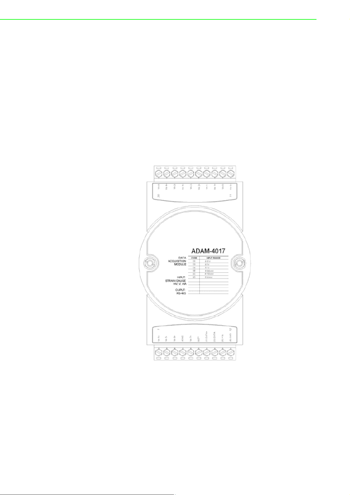
3.8.4 ADAM-4018+ 8-channel Thermocouple Input Module
Here comes a solution to the demand for more thermocouple input channels. Similar
to its counterpart, the ADAM-4018+ enables eight differential channels with multiple
input types. This multichannel/ multi-type structure allows synchronizing channels
with different types of input. For example, channel 1 has K type of input meanwhile
the others have R and S types.
ADAM-4018+ is an 8-channel T/C input module. Comparing with the universal analog
input module ADAM-4019, it is more dedicated to T/C and 4 ~ 20 mA inputs for those
with special request. It improves ADAM-4018 with the traditional design of six differential and two single-ended channels. It also enhances the steadiness and reliability
of the wiring. Normally, broken external wires will lead to an inaccurate current value.
ADAM-4018+, however, provides burned-out detection that allows users to fix the
problems easily. ADAM 4018+ has build in Shunt.
3.8.5 ADAM-4017 8-channel Analog Input Module
Figure 3.25 ADAM-4017 8-channel Analog Input Module
Channels:
- Six differential, two single-ended
Accepts:
- Millivolt inputs: ±150 mV and ±500 mV
- Volt inputs: ±1 V, ±5 V, and ±10 V
- Current input: ±20 mA (requires a 120 resistor)
The module forwards the data to the host computer in engineering units (mV, V or
mA)
ADAM-4000 Series User Manual 44
Page 59
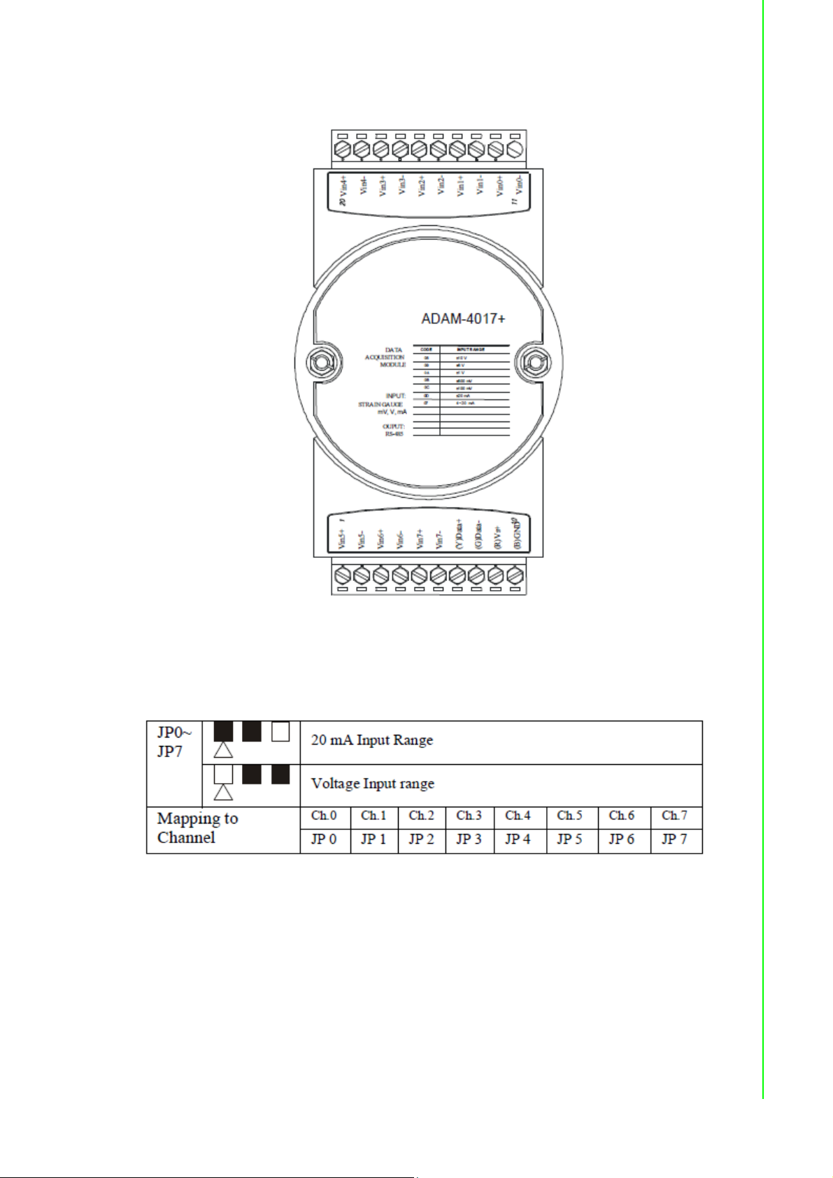
3.8.6 ADAM-4017+ 8-channel Differential Analog Input Module
Chapter 3 I/O Modules
Figure 3.26 ADAM-4017+ 8-ch. differential analog input module
Jumper setting (ADAM-4017+)
1. JP0~JP7
2. JP12 can Enable/Disable Watchdog Timer Function. The default setting is
closed, i.e., Watchdog Timer Function Enabled. Please always keep JP12
closed and enable/disable the watchdog timer function in ADAM-utility.
45 ADAM-4000 Series User Manual
Page 60

3.8.6.1 Technical Specification of ADAM-4017+
Table 3.3: Technical Specification of ADAM-4017+
Channel 8
Input Type mV, V, mA
Input Range ±150 mV, ±500 mV, ±1 V, ±5 V, ±10 V, ±20 mA, 4 ~ 20 mA
Current Input doesn’t need an external resistor
Isolation Voltage 3000 V
Fault and Over-voltage protection With stands over-voltage up to ±35 V
Sampling Rate 10 sample/sec (total)
Input Impedance Voltage: 20 M, Current: 120
Accuracy ±0.1% or better
Power Consumption 1.2 W @ 24V
I/O Connector Type 10 pin plug-in terminal
Span drift
Current Input: ±30 ppm/
Voltage Input: ±25 ppm/
DC
DC
o
C
o
C
3.8.7 ADAM-4018 8-channel Analog Input Module
Figure 3.27 ADAM-4018 8-channel Thermocouple Input Module
Channels:
- Six differential, two single-ended
Accepts:
ADAM-4000 Series User Manual 46
Page 61

- J, K, T, E, R, S and B thermocouples
- Millivolt inputs: ±15 mV, ±50 mV, ±100 mV and ±500 mV
- Volt inputs: ±1 V and ±2.5 V
- Current input: ±20 mA (requires a 125 resistor)
The module forwards the data to the host computer in engineering units (°C, mV, V or
mA)
3.8.8 ADAM-4018M 8-channel Analog Input Data logger
Chapter 3 I/O Modules
Figure 3.28 ADAM-4018M 8-channel Analog Input Data Logger
Channels:
- Six differential, two single-ended
Accepts:
- J, K, T, E, R, S and B thermocouples
- Millivolt inputs: ±15 mV, ±50 mV, ±100 mV, ±500 mV
- Volt inputs: ±1 V and ±2.5 V
- Current input: ±20 mA (requires a 125 resistor)
The module forwards the data to the host computer in engineering units (°C, mV, V,
or mA)
Storage Capacity:
- 128 KB flash memory
47 ADAM-4000 Series User Manual
Page 62
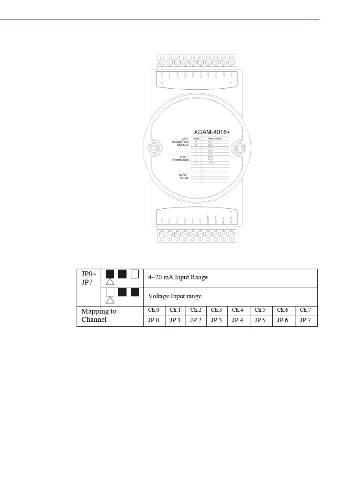
3.8.9 ADAM-4018+ 8-channel Thermocouple Input Module
Figure 3.29 ADAM-4018+ 8-ch. thermocouple input module
ADAM-4000 Series User Manual 48
Page 63
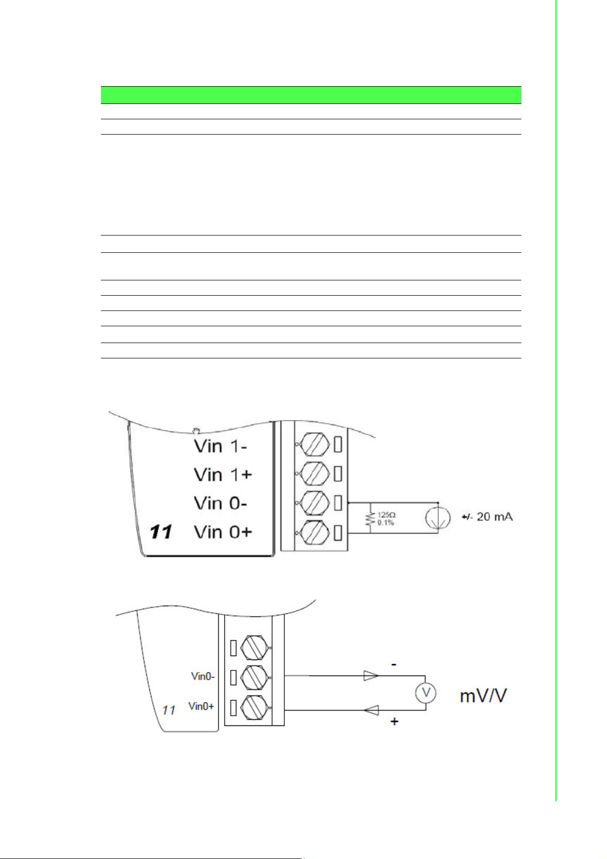
3.8.9.1 Technical specification of ADAM-4018+
Table 3.4: Technical specification of ADAM-4018+
Channel 8
Input Type T hermocouple
Input range and
T/C type
Isolation Voltage 3000 V
Fault and over-voltage
protection
Sampling Rate 10 sample/sec (total)
Input Impedance Voltage: 20 M, Current: 120
Accuracy ±0.1% or better
Power Consumption 0.8 W @ 24V
I/O Connector Type 10 pin plug-in terminal
±20 mA, 4~20 mA
J 0 ~ 760° C
K 0 ~ 1370° C
T -100 ~ 400° C
E 0 ~ 1000° C
R 500 ~ 1750° C
S 500 ~ 1750° C
B 500 ~ 1800° C
DC
Withstands over voltage up to ±35 V
DC
Chapter 3 I/O Modules
3.8.10 Application Wiring
Figure 3.30 Current Input Wiring Diagram of ADAM-4017
Figure 3.31 ADAM-4017 Differential Input Wiring Diagram (Ch0 ~ Ch5)
49 ADAM-4000 Series User Manual
Page 64
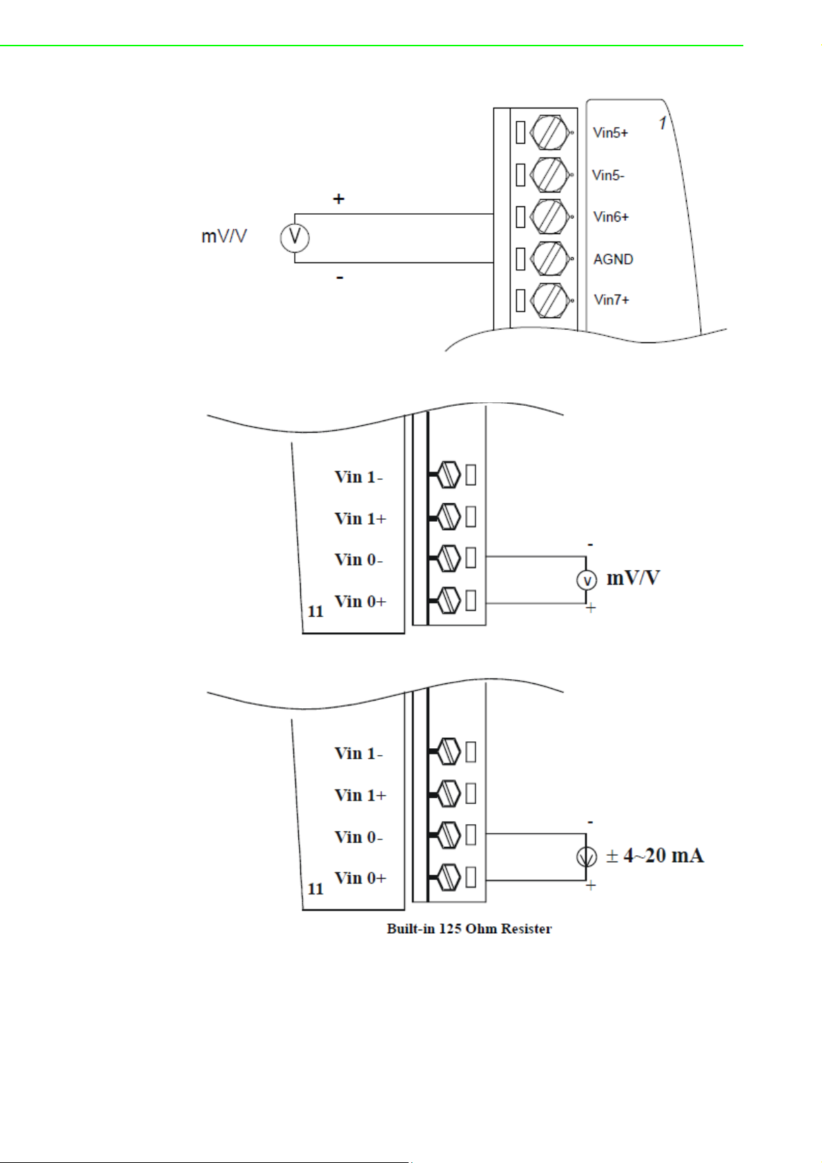
Figure 3.32 ADAM-4017 Single-ended Input Wiring Diagram (Ch6 and Ch7)
Figure 3.33 ADAM-4017+ Voltage and Current Input Wiring Diagram
ADAM-4000 Series User Manual 50
Page 65

Figure 3.34 ADAM-4018+ Thermocouple Input Wiring Diagram
3.9 ADAM-4019+ 8-channel Universal Analog Input
Module
The ADAM-4019+ is universal analog input module to integrate with various AI modules into one. It not only reduces the hardware cost, but also simplifies the wiring
complexity. Furthermore, the ADAM- 4019+ provides the burnt-out detection functionality for 4~20mA and all thermocouple input.
Chapter 3 I/O Modules
Figure 3.35 ADAM-4019+ 8-channel Universal Analog Input
51 ADAM-4000 Series User Manual
Page 66
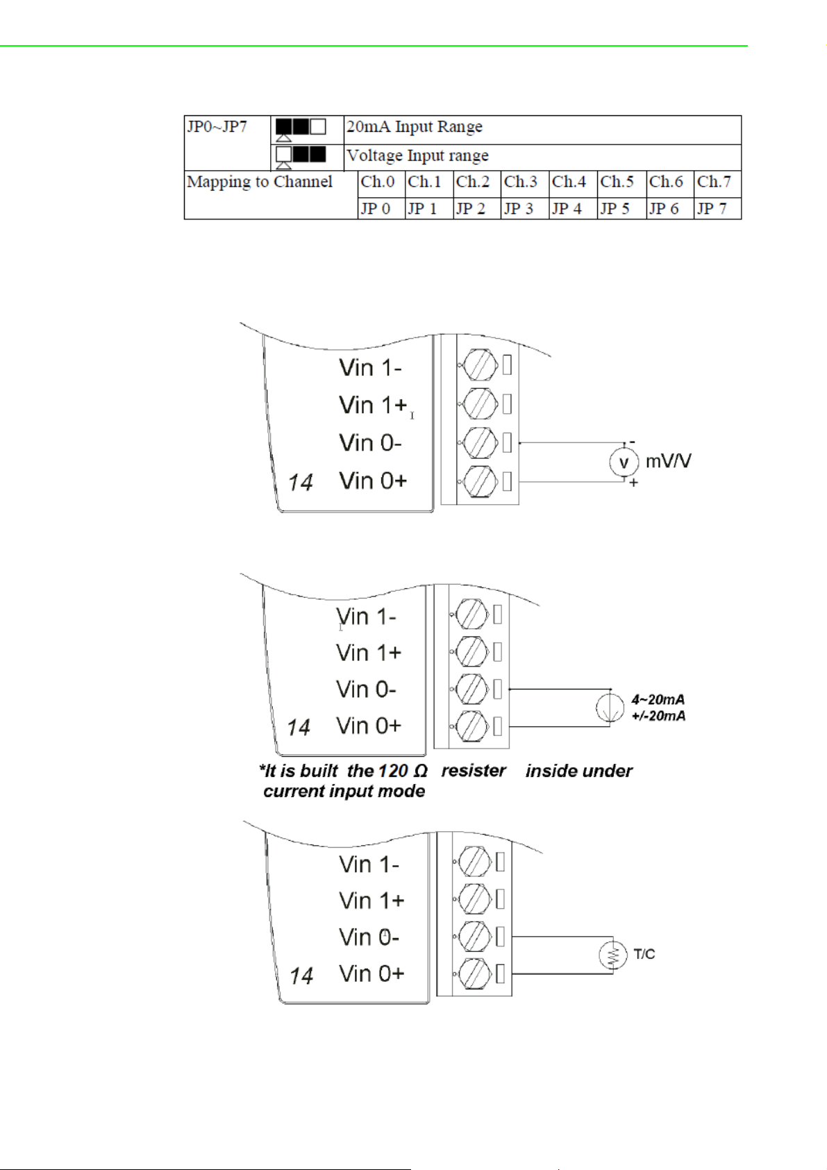
The jumper setting of ADAM-4019+ for input type selection:
*It is built the 120 resister inside under current input mode.
3.9.1 Application Wiring
Figure 3.36 ADAM-4019+ Universal Analog Input Wiring Diagram
ADAM-4000 Series User Manual 52
Page 67

3.9.2 Technical Specification of ADAM-4019+
Table 3.5: Technical Specification of ADAM-4019+
Channel 8
Resolution 16 bits
Input Type V, mV, mA, T/C
Input type and tempera-
ture range
Isolation Voltage 3000 VDC
Sampling Rate 10 samples/sec (total)
Input Impedance Voltage: 20 M, Current: 120
Accuracy ±0.1% or better
Power Consumption 1.0W @ 24V
I/O Connector Type 10 pin plug-in terminal
Burn-out Detection 4~20mA and all thermocouple input
V: ±1 V , ±2.5 V, ±5 V , ±10 V
mV: ±100 mV , ±500 mV
mA: ±20 mA (with 120 resister)
4~20mA (with 120 resister)
Thermocouple:
J 0 to 760 °C
K 0 to 1370 °C
T -100 to 400 °C
E 0 to 1000 °C
R 500 to 1750 °C
S 500 to 1750 °C
B 500 to 1800 °C
DC
Chapter 3 I/O Modules
3.10 ADAM-4021 Analog Output Module
Analog output module receives its digital input through an RS-485 interface from the
host computer. The format of the data is either two’s complement hexadecimal format
or percentage of full-scale range (FSR), depending on the module’s configuration. It
then uses its microprocessor-controlled D/A converter to convert the digital data into
output signals.
You will get a true read-back of the analog output signal from the unit’s ADC, which
monitors the output independently. You can also specify slew rates and start up currents through the configuration software. The Analog Output Module can supply single-channel analog output in a range of voltages or currents.
Furthermore, it will protect your equipment from power surges at the ground terminal
by providing opto-isolation of the D/A output and up to 3000 VDC transformer based
isolation.
Slew Rate
The slew rate is defined as the discrepancy between the present number of milliamps
(or Volts) per second and the required output currents (or voltages). An ADAM analog
output module may be configured for a specific slew rate.
53 ADAM-4000 Series User Manual
Page 68

Figure 3.37 ADAM -4021 Analog Output Module
Depending on its configuration settings the module accepts the following formats
from the host computer:
- Engineering units
- Percent of full-scale range (FSR)
- Two’s complement hexadecimal format,
Output types:
- Voltage: 0 ~ 10 V
(Slew rate: 0.0625 to 64 V/sec)
- Currents: 0 ~ 20 mA, or 4 ~ 20 mA.
(Slew rate: 0.125 to 128 mA/sec)
ADAM-4000 Series User Manual 54
Page 69

3.10.1 Application Wiring
Figure 3.38 ADAM-4021 Analog Output Wiring Diagram
3.11 ADAM-4024 4-channel Analog Output Module
ADAM-4024 is a 4-channel analog output module with mixed type I/O. Under some
circumstances, it is, however, a demand for multiple analog outputs to fulfill particular
applications without many duplicate modules. ADAM-4024 is designed to achieve
this purpose by integrating four A/O channels and four isolated D/I channels into only
one module. The four digital input channels function as an interlock for emergency
latch output.
ADAM-4024 inherited from ADAM-4021, but provide multi-range AO support, allows
its four A/O channels working at the same time with different and more output ranges.
For example, it can have 4~20 mA and ±10 V at its output. To ensure the operation of
machines and facilities, ADAM-4024 has the functionality of slew rate control. Output
slope is programmable through ramping/clamping the slew rate. Unlike traditional
mechanism, ADAM-4024 permits users to substitute its default value at the start up.
Users can easily set up and configure the module to be more adaptive.
Chapter 3 I/O Modules
Figure 3.39 ADAM-4024 4-channel Analog Output Module
55 ADAM-4000 Series User Manual
Page 70
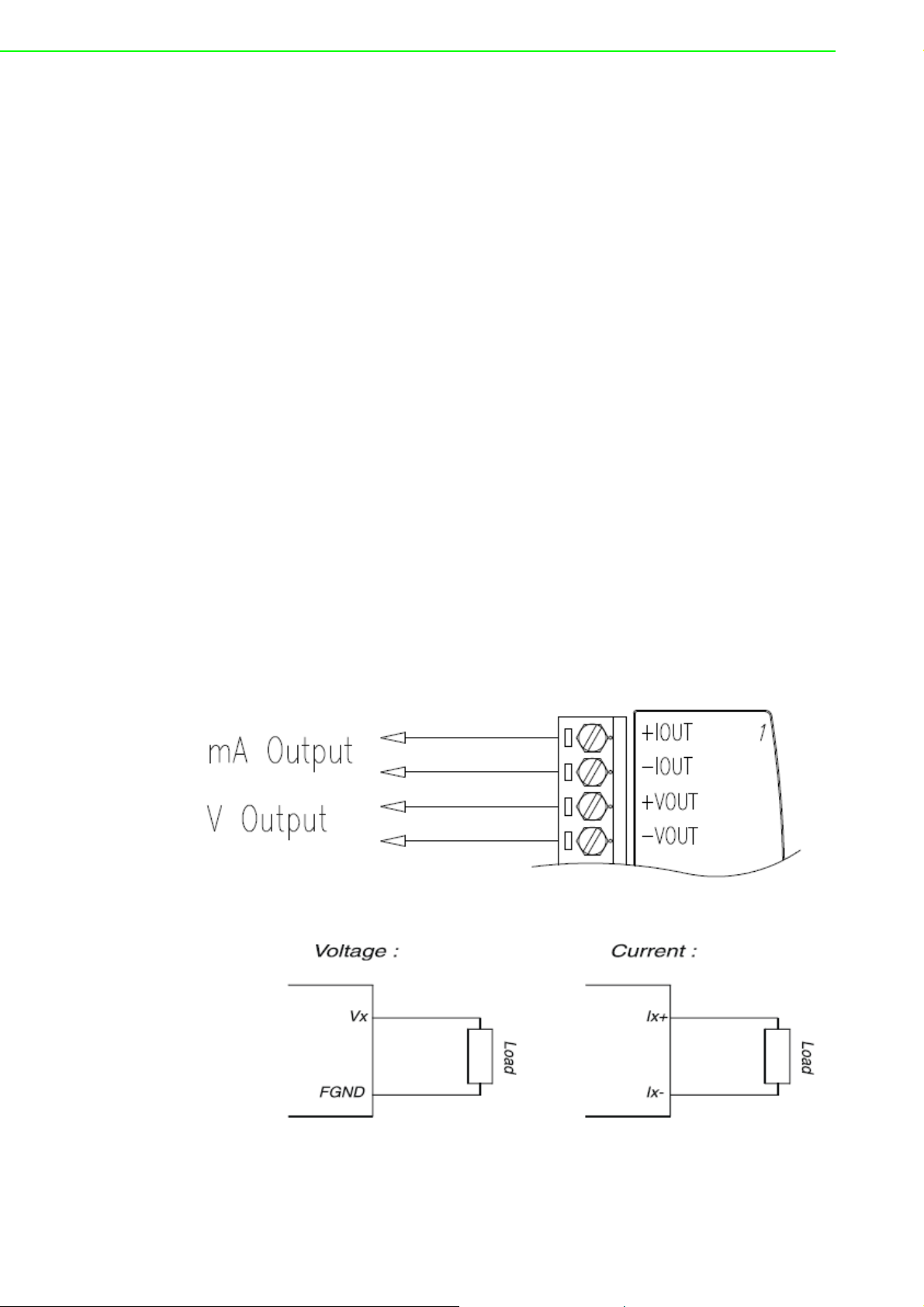
3.11.1 Technical specification of ADAM-4024
Resolution: 12-bit
Output Type: mA, V (Differential)
Output Range: 0~20 mA, 4~20 mA, and ±10V
Isolation Voltage: 3000 V
Output Impedance: 0.5
Accuracy:
– ±0.1% of FSR for current output
– ±0.2% of FSR for voltage output
Zero Drift:
– Voltage output: ±30 V/°C
– Current output: ±0.2 A/°C
Span Temperature Coefficient: ±25 ppm/°C
Output Slope Rate:
– 0.125 ~ 128 mA/sec.
– 0.0625 ~ 64 V/sec.
Current Load Resistor:Max. 500
Voltage Load Resistor:Min. 1K
Built-in Watchdog Timer
Isolation Digital Input
– Channel: 4
– Level 0: +1V max
– Level 1: +10~30 V
DC
DC
3.11.2 Application Wiring
ADAM-4000 Series User Manual 56
Page 71

Chapter 3 I/O Modules
Figure 3.40 ADAM-4024 Pin Define and Wiring Diagram
3.12 ADAM-4050 Digital I/O Module
The ADAM-4050 features seven digital input and eight digital output channels. The
outputs are open-collector transistor switches that you can control from the host computer. You can also use the switches to control solid-state relays, which can be
applied to equipments such as heaters and pumps. The host computer can use the
module's digital inputs to determine the states of limit, safety switches, and remote
digital signals.
57 ADAM-4000 Series User Manual
Page 72
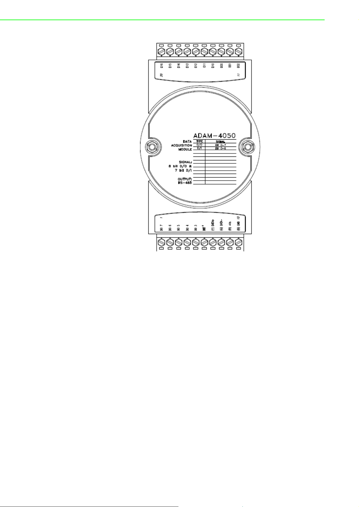
Figure 3.41 ADAM-4050 Digital I/O Module
Channels:
- 7 input channels
- 8 output channels
Digital Input:
- Logic level 0: +1 V max.
- Logic level 1: +3.5 ~ 30 V
Digital Output:
- Open collector to 30 V, 30 mA max. load
ADAM-4000 Series User Manual 58
Page 73

3.12.1 Application Wiring
Figure 3.42 ADAM-4050 TTL Input Wiring Diagram
Chapter 3 I/O Modules
Figure 3.43 ADAM-4050 Contact Closure Input Wiring Diagram
Figure 3.44 ADAM-4050 Digital Output Wiring Diagram Used with SSR
59 ADAM-4000 Series User Manual
Page 74
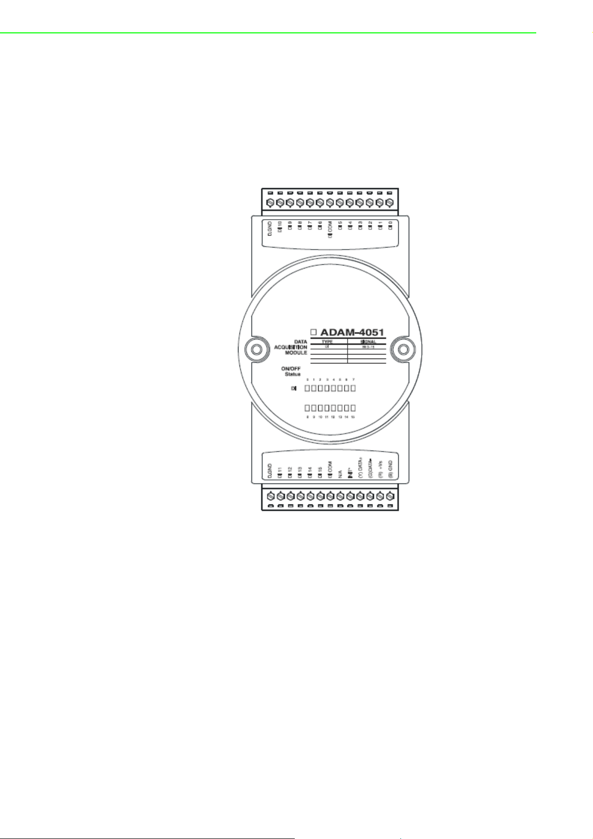
3.13 ADAM-4051 16-channel Isolated Digital Input
Module
The ADAM-4051 is a 16 channel Digital Input Module. It is built with 2500VDC optical
isolation, and it is suitable for critical applications. The main difference from other
modules is that ADAM-4051 accepts 10 ~ 50V input voltage to fit various digital signals like 12 V, 24 V, and 48 V. Moreover, users can read the current status from the
LED indicators on the front panel.
Figure 3.45 ADAM-4051 16-channel Isolated Digital Input Module
Channel: 16
Optical Isolation: 2500 VDC
Opto-isolator response time: 25 s
Over-voltage Protect: 70 VDC
ESD (Electro Static Discharge): 2000 VDC
LED Indicator: On: Active; Off: Non-active
Input Voltage:
– Dry Contact Logic level 1: close to GND, Logic level 0: open
– Wet Contact Logic level 1: 10 ~ 50 V, Logic level 0: 3 V
Power consumption: 1W @ 24 VDC
I/O Connector Type: 13 pin plug-in terminal*2
ADAM-4000 Series User Manual 60
Page 75
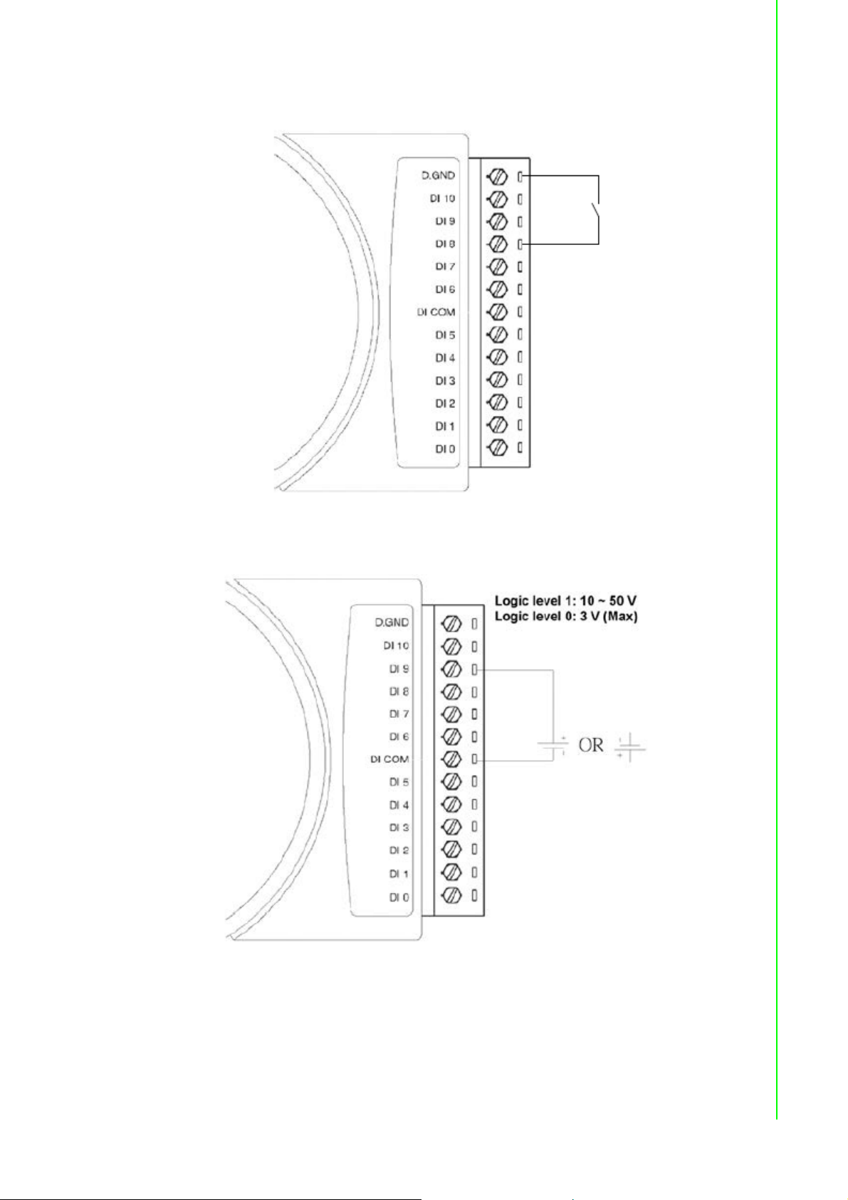
3.13.1 Application Wiring
Chapter 3 I/O Modules
Figure 3.46 ADAM-4051 Dry Contact Wiring Diagram
Figure 3.47 ADAM-4051 Wet Contact Wiring Diagram
61 ADAM-4000 Series User Manual
Page 76

3.14 ADAM-4052 Isolated Digital Input Module
The ADAM-4052 provides eight digital input channels. Among these eight channels,
six of them are fully independent isolated channels and the other two are isolated
channels with a common ground. They all have 5000 V
power surges from the input lines
isolation to prevent
RMS
Figure 3.48 ADAM-4052 Isolated Digital Input Module
Channels: 8
- 6 differential channels (fully independent isolated channels)
- 2 single-ended channels (isolated channels with common ground)
Digital Input:
- Logic level 0: +1 V max.
- Logic level 1: +3 ~ 30 V
ADAM-4000 Series User Manual 62
Page 77
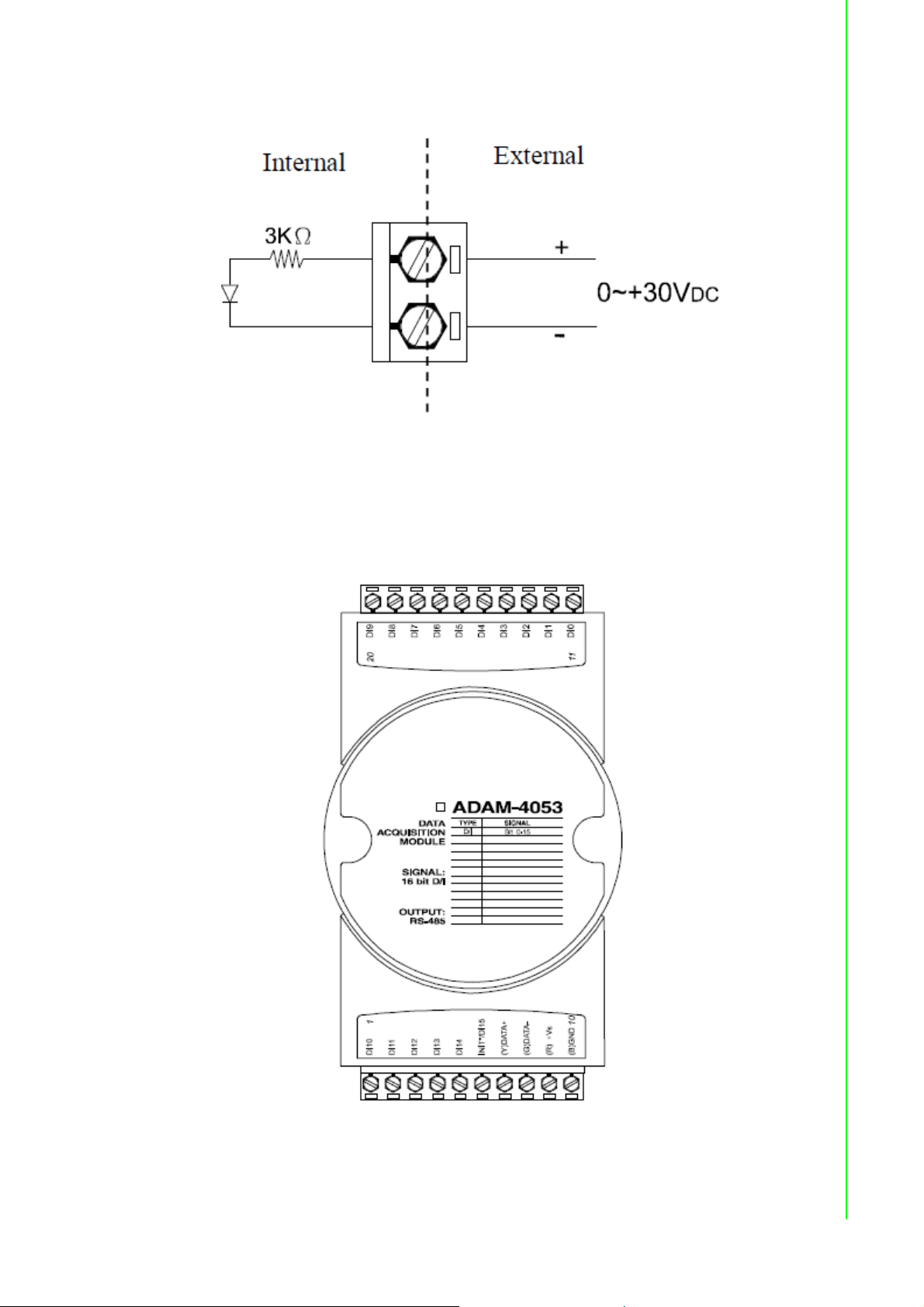
3.14.1 Application Wiring
Figure 3.49 ADAM-4052 Isolation Digital Input Wiring Ground
3.15 ADAM-4053 16-channel Digital Input Module
The ADAM-4053 provides 16 digital input channels for dry contact or wet contact signals. For dry contact, the effective distance from DI to contact point is up to 500 m.
Chapter 3 I/O Modules
Figure 3.50 ADAM-4053 16-channel Digital Input Module
63 ADAM-4000 Series User Manual
Page 78
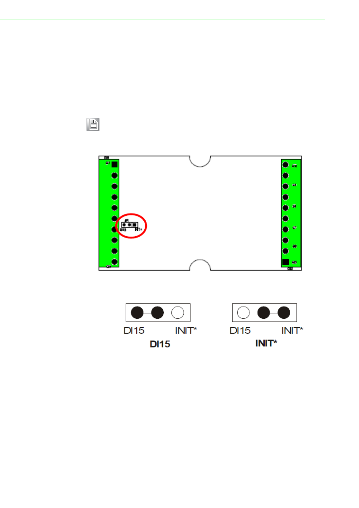
Channels: 16 Digital Input
-Dry contact
Logic level 0: Close to GND
Logic level 1: OPEN
-Wet contact
Logic level 0: +2 V max.
Logic level 1: +4 V to +30 V
Note! There is one pin showing “INIT*/DI15” on the connector of the ADAM-
4053 module. You can configure the pin define by the jumper on PCB
(refer to the image below to see its location):
Jumper Setting:
ADAM-4000 Series User Manual 64
Page 79
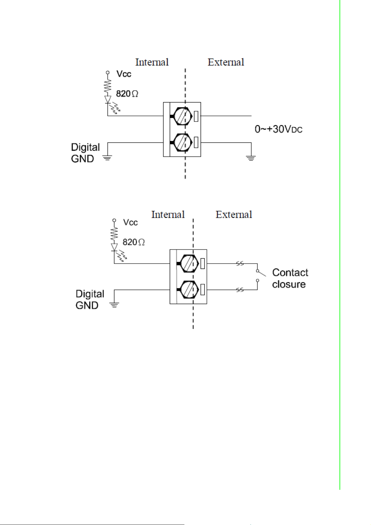
3.15.1 Application Wiring
Figure 3.51 ADAM-4053 Wet Contact Input Wiring Diagram
Chapter 3 I/O Modules
Figure 3.52 ADAM-4053 Contact Closure Input Wiring Diagram
65 ADAM-4000 Series User Manual
Page 80

3.16 ADAM-4055 16-channel Isolated Digital I/O
Module
The ADAM-4055 offers 8 channel isolated digital input and 8 channel isolated digital
output for critical applications. The inputs accept 10~50 V voltage, and the outputs
can supply 5~40 VDC at the open collector. The ADAM-4055 is user friendly with
built LED indicator for status reading.
Notice: We had updated the digital input dry/wet contact option by using jumper
selection. The default setting is to support these two DI contacts both at the same
time. However, a customer can also choose his or her needs by supporting only one.
Please refer to the following wiring illustration figure 3-53 for more details.
Figure 3.53 ADAM-4055 16-channel Digital I/O Module
ADAM-4000 Series User Manual 66
Page 81
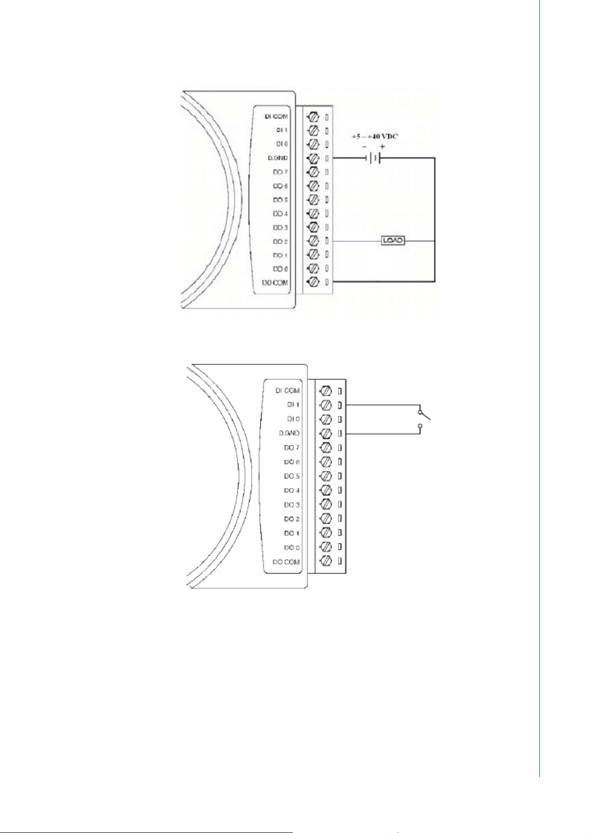
3.16.1 Application Wiring:
Figure 3.54 ADAM-4055 Digital Output Wiring Diagram
Chapter 3 I/O Modules
Figure 3.55 ADAM-4055 Digital Input Dry Contact Wiring Diagram
67 ADAM-4000 Series User Manual
Page 82

Figure 3.56 ADAM-4055 Digital Input Dry Contact Diagram (Internal)
Figure 3.57 ADAM-4055 Digital Input Wet Contact Wiring Diagram
ADAM-4000 Series User Manual 68
Page 83

Chapter 3 I/O Modules
Figure 3.58 ADAM-4055 Digital Input Wet Contact Diagram (Internal)
Figure 3.59 ADAM-4055 Default Jumper Setting for the Digital Input Wiring
(Support dry and wet contact digital input at the same time)
69 ADAM-4000 Series User Manual
Page 84

Figure 3.60 ADAM-4055 Default Jumper Setting for the Digital Input Wiring
ADAM-4000 Series User Manual 70
Page 85

3.17 ADAM-4056S 12-channel Sink Type Isolated
Digital Output Module
ADAM-4056S is a 12-channel sink type isolated digital output module. The isolated
channels are designed for digital output for critical applications. Open collector outputs can provide from +5 to +40 VDC, and both ADAM ASCII and Modbus/RTU protocols are supported. LED indicators are used for status reading.
Chapter 3 I/O Modules
Figure 3.61 ADAM-4056S 12-channel Sink Type Isolated Digital Output Module
3.17.1 Technical Specification of ADAM-4056S
Number of Output Channel: 12
Digital Output:
Open Collector from +5 ~ +40V, 200mA max. load (Sink)
LED Indicator: On: Active, Off: Non-active
Power Consumption: 1 W @ 24V
Optical isolation: 5000 V
Supports Modbus/RTU protocol
I/O Connector Type: 10 pin plug-in terminal*2
Support Safety Value:
Force the DO channels to safety status when communication is in time-out and
over pre-defined period.
DC
DC
71 ADAM-4000 Series User Manual
Page 86

3.17.2 Application Wiring
Figure 3.62 ADAM-4056S Digital Output Wiring Diagram
3.18 ADAM-4056SO 12-channel Source Type Isolated
Digital Output Module
ADAM-4056SO is a 12-channel source type isolated digital output module. The 12
isolated digital output channels are designed for critical applications. The digital output signals are sent in the range of 10 ~ 35 VDC with maximum 1A per channel, and
both ADAM ASCII and Modbus/RTU protocols are supported. The LED indicators
provide status reading of the module.
ADAM-4000 Series User Manual 72
Page 87

Chapter 3 I/O Modules
Figure 3.63 ADAM-4056SO 12-channel Source Type Isolated Digital Output
Module
3.18.1 Technical Specification of ADAM-4056SO
– Number of Output Channel: 12
– Digital Output: VCC: +10 ~ 35VDC, 1A per Channel ( Source)
– LED Indicator: On: Active, Off: Non-active
– Power Consumption: 1 W @ 24VDC
– Optical isolation: 5000 VDC
– Supports Modbus/RTU protocol
– ?/O Connector Type: 10 pin plug-in terminal*2
– Leakage current : 50A
– Support Safety Value:
Force the DO channels to safety status when communication is in time-out
and over pre-defined period.
73 ADAM-4000 Series User Manual
Page 88

3.18.2 Application Wiring
Figure 3.64 ADAM-4056SO Digital Output Wiring Diagram
3.19 ADAM-4060/4068 Relay Output Module
The ADAM Relay Output Module is a low-cost alternative to SSR modules. The
ADAM-4060 Relay Output Module provides four relay channels; two of them are
Form A, and two are Form C. The ADAM- 4068 Relay Output Module provides eight
channels. Four of the channels are Form A, and four are Form C. These two modules
are excellent for ON/OFF control or low-power switching applications and they are
able to support the safety value setting.
ADAM-4000 Series User Manual 74
Page 89
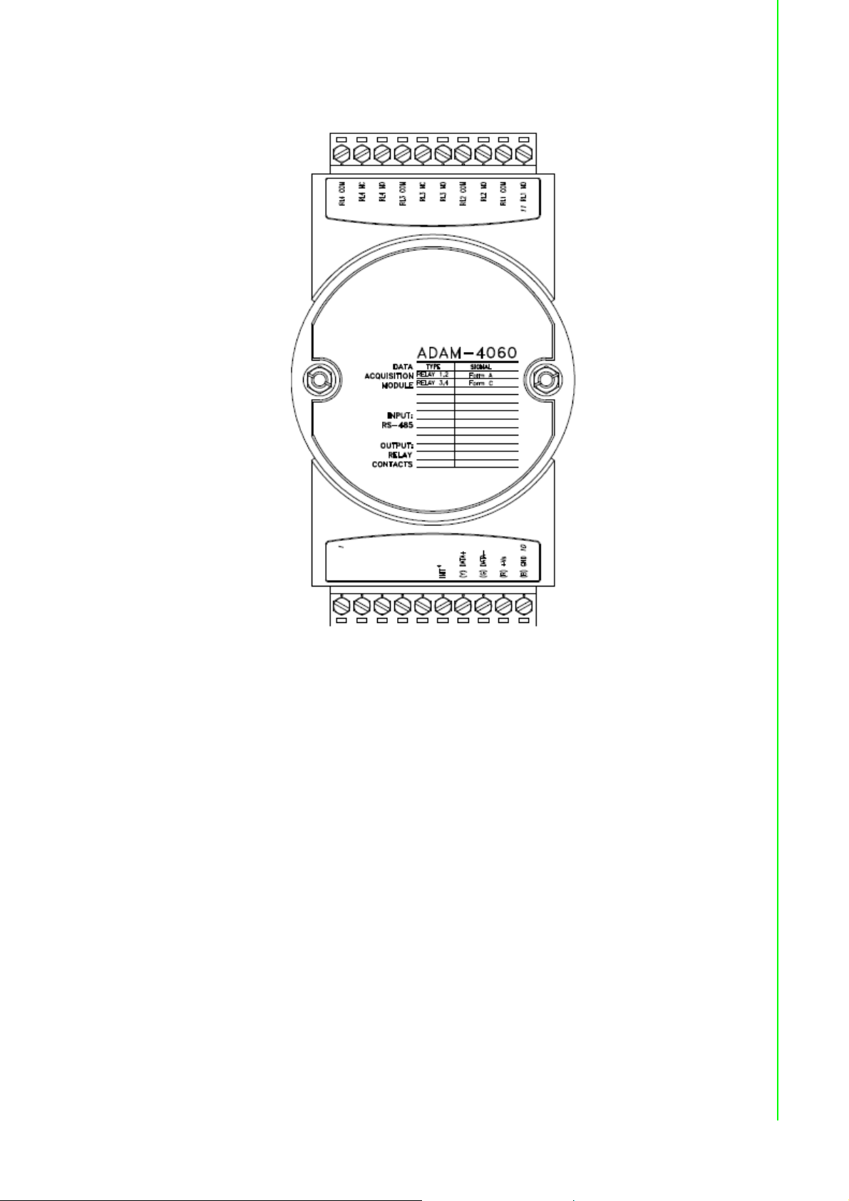
3.19.1 ADAM-4060 4-channel Relay Output Module
Chapter 3 I/O Modules
Figure 3.65 ADAM-4060 4-channel Relay Output Module
Contact rating for Form A and Form C: (Resistive)
AC 0.6 A @ 125 V
0.3 A @ 250 V
DC 2 A @ 30 V
0.6 A @ 110 V
75 ADAM-4000 Series User Manual
Page 90
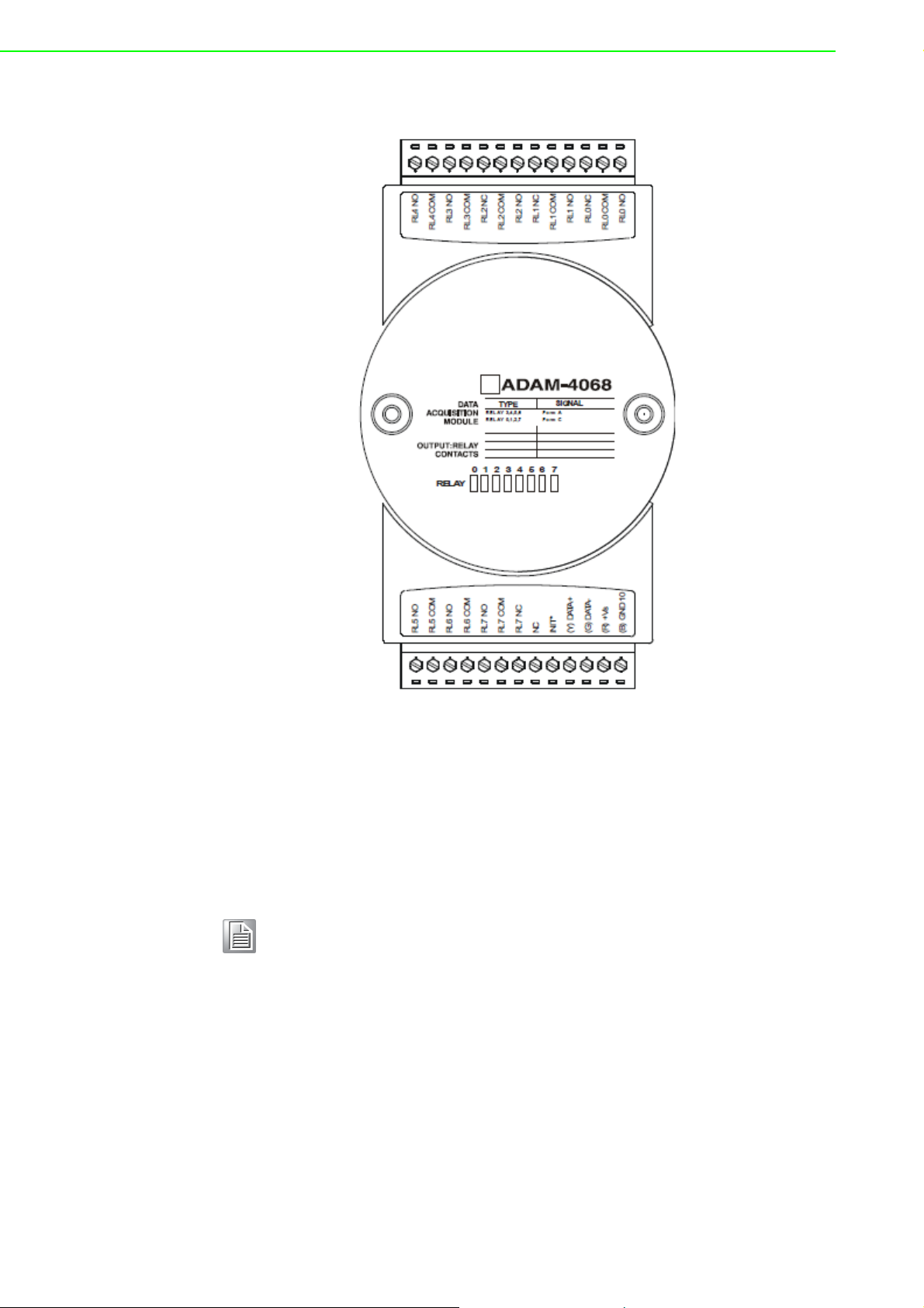
3.19.2 ADAM-4068 8-channel Relay Output Module
Figure 3.66 ADAM-4068 8-channel Relay Output Module
Contact Rating for Form A and Form C: (Resistive)
AC 0.5 A @120 V
0.25 A @240 V
DC 1 A @ 30 V
0.3 A @ 110 V
Note! This electric current is under the load of resistance. If you try to use the
load of inductance, the electric current would be less the above-mentioned value.
ADAM-4000 Series User Manual 76
Page 91
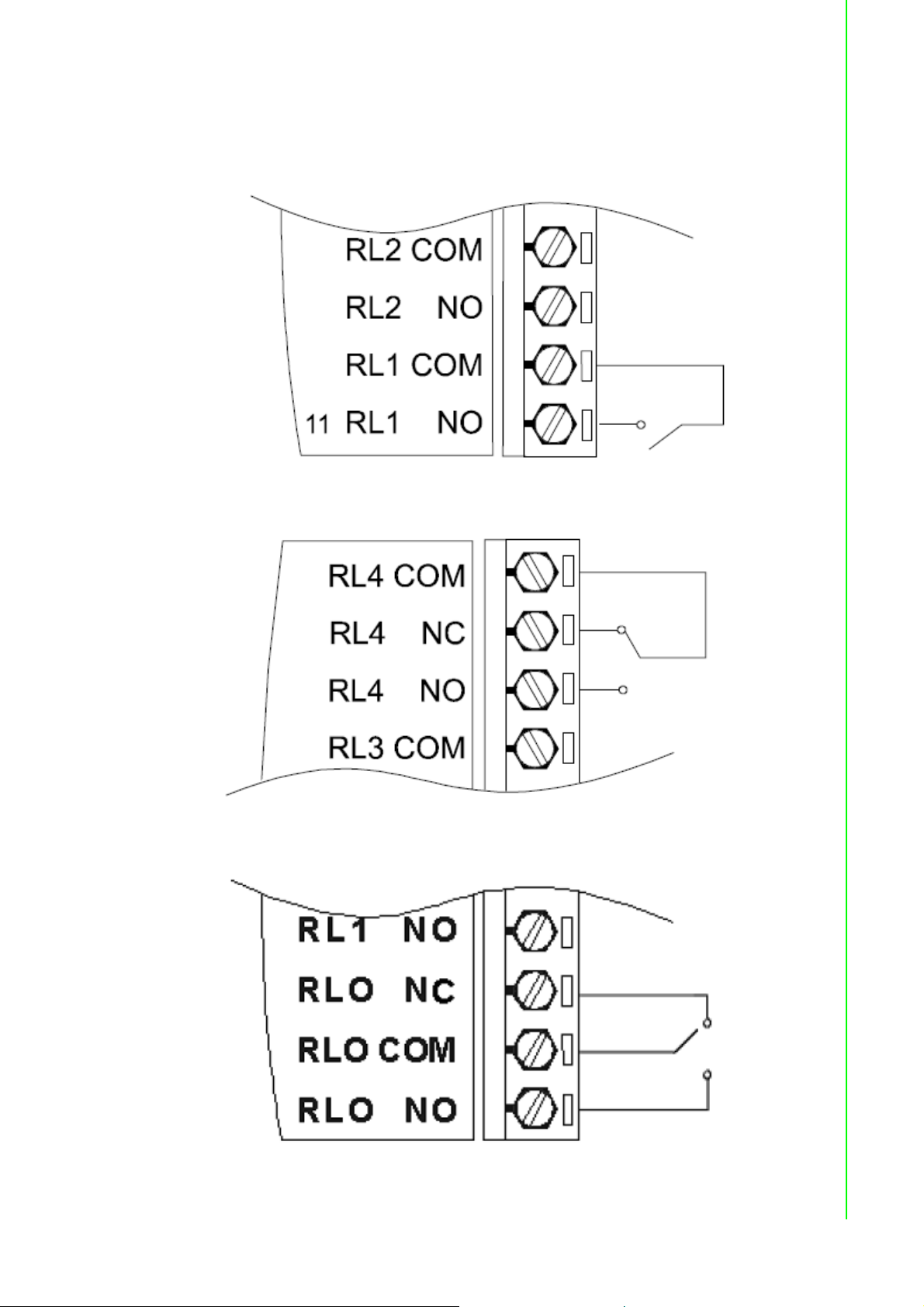
3.19.3 Application Wiring
The following diagrams are examples of how to connect Form A and Form C relay
output applications to your ADAM modules.
Figure 3.67 ADAM-4060 Form A Relay Output Wiring Diagram
Chapter 3 I/O Modules
Figure 3.68 ADAM-4060 Form C Relay Output Wiring Diagram
Figure 3.69 ADAM-4068 Form C Relay Output Wiring Diagram
77 ADAM-4000 Series User Manual
Page 92

Figure 3.70 ADAM-4068 Form A relay output Wiring Diagram
3.20 ADAM-4069 8-channel Relay Output Module
The ADAM-4069 Relay Output Module provides eight channels; four are Form A and
the rest are Form C. This module is excellent for ON/OFF control or low-power
switching applications.
Figure 3.71 ADAM-4069 Relay Output Module
ADAM-4000 Series User Manual 78
Page 93

3.20.1 Specification
Number of Relay Output Channel: 8
Digital Output: (Source)
– 4 Form A, 4 Form C
– AC 5A@250V
– DC 5A@30V
– ON/OFF : 5ms/ 5.6ms
Power Consumption: 2.2 W
Supports Modbus/RTU protocol
I/O Connector Type: 13-pin plug-terminal * 2
Support Safety Value: Force the DO channels to safety status when communi-
cation is in time-out and over pre-defined period.
3.20.2 Wiring
Chapter 3 I/O Modules
Figure 3.72 ADAM-4069 Form C Relay Output
Figure 3.73 ADAM-4069 Form A Relay Output
79 ADAM-4000 Series User Manual
Page 94

3.21 ADAM-4080/4080D Counter/Frequency Input
Modules
ADAM-4080/4080D Counter/frequency input module has two 32- bit counter input
channels (counter 0 and counter 1) with built-in programmable timer for frequency
measurement. These cost-effective modules let you monitor counter/frequency data
as measurements are taken.
Front Panel LED Indicator (ADAM-4080D only)
The 5-digit LED display of the ADAM-4080D lets you monitor its counter data right at
the source. The module's LED display shows counter values as well as high-low
alarm messages when the counter exceeds its programmed limits (direct display).
Another option is to display the data sent by the host computer. The module first
sends counter data to the host computer for conversion or calculation. The host computer then sends the data back to the ADAM- 4080D and displays on the module's
LED display (remote display).
Signal Input Mode
The ADAM-4080/4080D provides separate terminals for photo isolated input and
non-isolated input to simplify the wiring. Optoisolated input provides 2500 V
lation to protect your equipment from power surges at the ground terminal. After you
make the physical connections, program the module to identify which of its two input
terminals should be activated (isolated or non-isolated terminals).
RMS
iso-
Programmable Digital Filter
The ADAM-4080/4080D module includes a unique programmable digital filter to
reject noise from the input lines. You can specify separate time constant like minimum signal width at high level and minimum signal width at low level. This provides
stable output readings.
Programmable Threshold
When the ADAM-4080/4080D is programmed for non-isolated input, you can set a
high and low trigger level. Like the programmable digital filter, the programmable
threshold rejects noise from the input lines and provides a stable input readings
External Control (Gate mode)
Aside from the GND and counter terminal, each channel has a gate terminal to connect to an external gate signal. The gate signal (high or low) can trigger the counter
from start or stop counting. The gate mode can be among these three options, low,
high or disabled (low means that counting starts when the gate signal is low. It stops
once the gate signal becomes high)
Programmable Alarm Output
The ADAM-4080 module provides a configurable alarm for each counter. The ADAM4080D provides high and low alarm functions for counter 0. When the counter
reaches an alarm limit, it will trigger the built-in digital output of machine ON/OFF
control. The alarm limits may be downloaded into the module's EEPROM by the host
computer. The initial count value of ADAM-4080 module's counter can be configured
in any values.
ADAM-4000 Series User Manual 80
Page 95
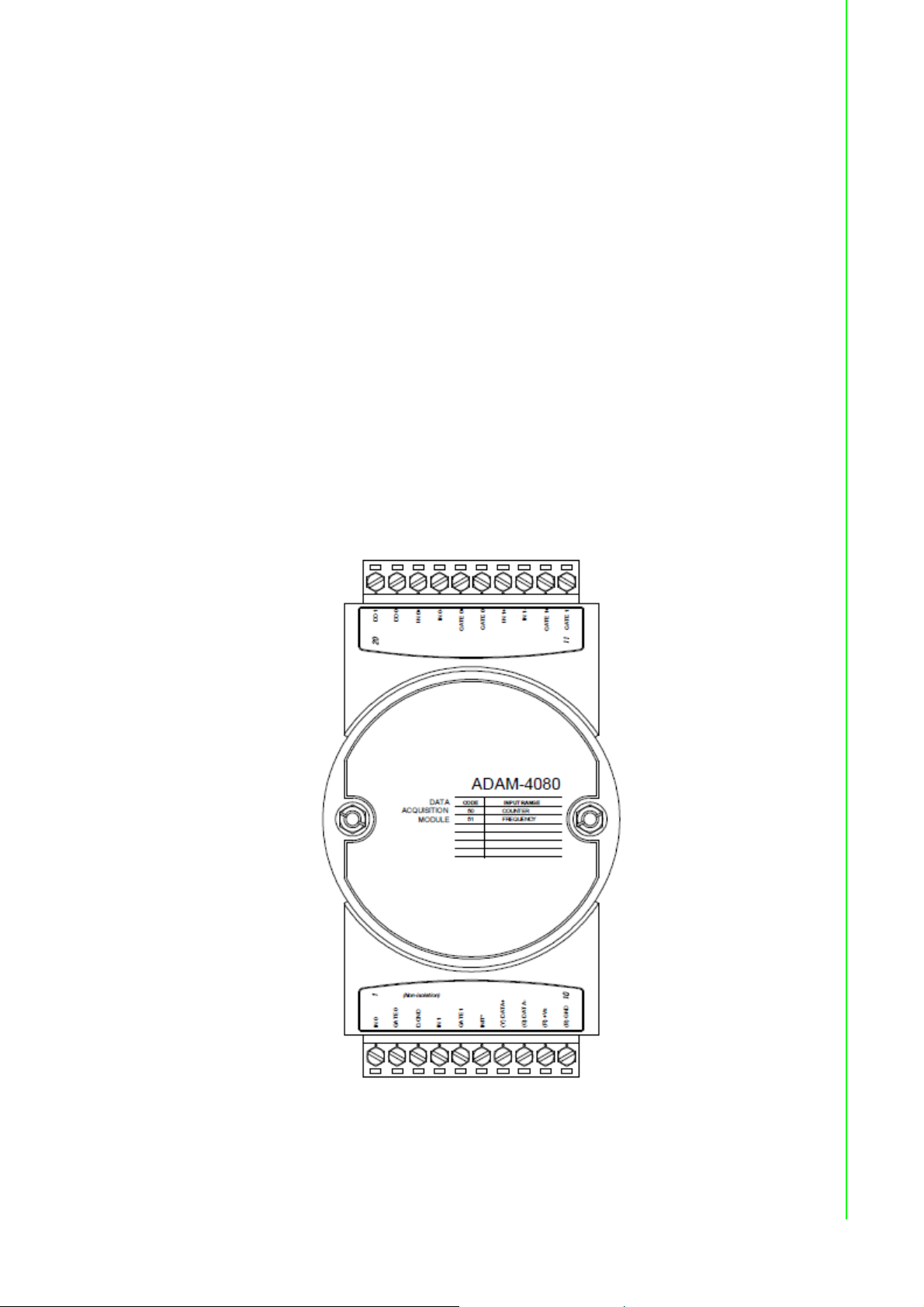
The alarm functions can be enabled or disabled remotely. When the alarm functions
are enabled, digital output channels are used to indicate the alarm states. For ADAM4080, digital output channel 0 equals to the alarm state of counter 0, and digital output channel 1 equals to the alarm state of counter 1. For ADAM-4080D, digital output
channel 0 equals to the low alarm state of counter 0, and digital output channel 1
equals to the high alarm state of counter 0.
Every A/D conversion will be followed by a comparison of alarm limits. If the input
value exceeds one of these limits, the corresponding alarm state is set to ON.
There are two alarm mode options, momentary and latching, for ADAM-4080D. If the
alarm is in latching mode, the alarm will stay on even when the input value returns
within the limits. An alarm in latching mode can be turned off by issuing a Clear Alarm
command from the host computer. A latching alarm is cleared by the module when
the opposite alarm is set. For example, the alarm is in latching mode and the high
alarm is then turned ON. When the module receives a value that is lower than the low
alarm limit, it will clear the high alarm and turn the low alarm ON.
When the alarm is in Momentary mode, the alarm will be turned OFF as soon as the
input value returns within the limits. The arrangement of coupling high and low alarm
states with digital output lines may be utilized to build ON/OFF controllers that can
operate without the host computer involvement.
3.21.1 ADAM-4080 Counter/Frequency Input Modules
Chapter 3 I/O Modules
Figure 3.74 ADAM-4080 Counter/Frequency Input Module
81 ADAM-4000 Series User Manual
Page 96

Channels: 2 independent 32-bit counters (counter 0 and counter 1)
Input frequency: 50 kHz max.
Input mode: Isolated or non-isolated
Isolation input level:
- Logic level 0: +1 V max
- Logic level 1: +3.5 V to +30 V
- Input Impedance: 1.2 k
Non-isolation input level (programmable threshold):
- Logic level 0: 0 to +5V (default = 0.8 V)
- Logic level 1: 0 to +5V (default = 2.4 V)
- Input Impedance: 50 M
3.21.2 ADAM-4080D Counter/Frequency Input Modules with LED
Display
Figure 3.75 ADAM-4080D Counter/Frequency Input Module with LED Display
Channels: 2 independent 32-bit counters (counter 0 and counter 1)
Input frequency: 50 kHz max.
Input mode: Isolated or non-isolated
Isolation input level:
- Logic level 0: +1 V max
- Logic level 1: +3.5 V to +30 V
- Input Impedance: 1.2 k
ADAM-4000 Series User Manual 82
Page 97

Non-isolation input level (programmable threshold):
- Logic level 0: 0 to +5V (default = 0.8 V)
- Logic level 1: 0 to +5V (default = 2.4 V)
- Input Impedance: 50 M
3.21.3 Application Wiring
Figure 3.76 ADAM-4080/4080D Non-isolated Input
Chapter 3 I/O Modules
Figure 3.77 ADAM-4080/4080D Photo-isolated Input
83 ADAM-4000 Series User Manual
Page 98

ADAM-4000 Series User Manual 84
Page 99

Chapter 4
4 Command Set
Page 100

4.1 Introduction
In order to avoid communication conflicts among devices trying to send data simultaneously, all the traffics are coordinated by the host computer. This action is initiated
by the host computer using a command/response protocol.
When the modules are not transmitting, they are in listening mode. The host issues a
command to a module with a specified address and waits for the module’s response.
If there is no response, a timeout aborts the sequence and returns the control to the
host.
Changing ADAM’s configuration might require the module to perform auto calibration
before changes may take effect. This is the case when the range is modified especially. The module has to perform all stages of auto calibration which is also performed during the start up. When the calibration process is underway, the module
does not respond to any other commands. The command set in the following pages
includes the exact delays that might occur as modules are reconfigured.
4.2 Syntax
[delimiter character][address][command][data][checksum] [carriage return]
Every command begins with a delimiter character. There are four valid characters: a
dollar sign $, a pound sign #, a percentage sign % and an at sign @.
The delimiter character is followed by a two-character address (hexadecimal) that
specifies the target module. The actual two-character command follows by the
address. Depending on the command, an optional data segment may follows by a
command string. Furthermore, an optional two-character checksum may be
appended to the total string. Every command is terminated by a carriage return (cr).
ALL COMMANDS SHOULD BE ISSUED IN UPPERCASE CHARACTERS!
Before the command set is given, we provide an I/O module commands search table
to help you find the commands that you wish to use. The command set is divided into
the following three categories:
Analog Input Module commands
Analog Output Module commands
Digital I/O, Relay Output and Counter/Frequency Module commands
Each Category starts with a command summary of a particular type of module. However, they are explained in more depth at Chapter 5, 6 & 7 with detailed datasheets of
each individual commands.
Although commands in different subsections sometimes share the same format, the
effect they have on a certain module can be completely different from others. For
example, the configuration command %AANNTTCCFF affects analog input modules
and analog output modules differently. The full command set for every module is
listed below.
ADAM-4000 Series User Manual 86
 Loading...