

Page 1

ADAM-5000 Series
RS-485 Based Data Acquisition
and Control System
User’s Manual
Page 2

Copyright Notice
This document is copyrighted, 2001, by Advantech Co.,
Ltd. All rights are reserved. Advantech Co., Ltd., reserves the
right to make improvements to the products described in this
manual at any time without notice.
No part of this manual may be reproduced, copied, translated
or transmitted in any form or by any means without the prior
written permission of Advantech Co., Ltd. Information
provided in this manual is intended to be accurate and
reliable. However, Advantech Co., Ltd. assumes no
responsibility for its use, nor for any infringements upon the
rights of third parties which may result from its use.
Acknowledgment
ADAM is a trademark of Advantech Co., Ltd. IBM and PC
are trademarks of International Business Machines Corporation.
CE Nonification
The ADAM-5000 series developed by Advantech Co.,
Ltd. has passed the CE test for environmental specifications. Test
conditions for passing included the equipment being operated
within an industrial enclosure, using shielded twisted-pair RS-485
cables and having SFC-6 sleeve core clamps added to the power
cable and the RS-485 cable. In order to protect the ADAM-5000
system from being damaged by ESD (Electrostatic Discharge) and
EMI leakage, we strongly recommend the use of CE-compliant
industrial enclosure products, shielded twisted-pair RS-485 cables,
and core clamps.
Edition 7.3
Aug. 2007
Page 3

A Message to the Customer…..
Advantech Customer Services
Each and every Advantech product is built to the most exacting
specifications to ensure reliable performance in the unusual and
demanding conditions typical of i ndustri al envir onm ents. Whet her
your new Advantech equipment is destined for the laboratory or
the factory floor, you can be assured that your product will provide
the reliability and ease of operation for which the name Advantech
has come to be known.
Your satisfaction is our number one concern. Here is a guide to
Advantech’s customer services. To ensure you get the full benefit
of our services, please follow the instructions below carefully .
Technical Support
W e want you to get t he maximum performance from your products .
So if you run into technical difficulties, we are here to help. For
most frequently asked questions you can easily find answer s in
your product documentation. These answers are normally a lot
more detailed than the ones we can give over the phone.
So please consult this manual first. If you still can’t find the answer ,
gather all the information or que stions that apply t o y our pro blem
and, with the product close at hand, call your dealer . Our dealers
are well trained and ready to give you the support you need to get
the most from your Advantech prod ucts. In f act, m ost pr obl em s
reported are minor and are able to be easily solved over the phone.
In addition, free technical s upport is availabl e from Advant ech
engineers every business day. We are always ready to give advice
on application requirements or specific information on the installation and operation of any of our p roduc ts.
Page 4

Product Warranty
Advantech warrants to you, the original purchaser, that each of its
products will be free from defects in materials and workmanship for
one year from the date of purchase.
This warranty does not apply to any products which have been
repaired or altered by other t han repair personnel authorized by
Advantech, or which have been subject to misuse, abuse, accident
or improper installation. Advantech assumes no liability as a
consequence of such events under the terms of this Warranty.
Because of Advantech’s high quality-control standards and
rigorous testing, most of our customers never need to use our
repair service. If an Advantech product ever does prove defective,
it will be repaired or replaced at no charge during the warranty
period. For out-of-warranty repairs, you will be billed according to
the cost of replacement materials, service time and freight. Please
consult your dealer for more details.
If you think you have a defective product, follow these steps:
1 . Collect all the information about the problem encountered
(e.g. type of PC, CPU speed, Advantech products used, other
hardware and software used etc.). Note a nythi ng abnorm al and
list any on-screen messages you get when the problem occurs.
2 . Call your dealer and describe the problem. Please have your
manual, product, and any helpful information readil y available.
3. If your product is diagnosed as defective, you have to
request an RAM number . When requesting a n RMA (Return
Material Authorization) number, please access ADVANTECH's
RMA website: http://www.advantech.com.tw/rma. If the web
sever is shut down, please contact our of fice directly. Y ou
should fill in the "Problem Repair F orm", desc ribing in detail
the applicatio n environm ent, config uration, a nd probl ems
encountered. Note that error descriptions such as "does not
work" and "failure" are so general that we are then required to
apply our internal standard repair process.
Page 5

4 . Carefully pack the defective product, a completely filled-out
Repair and Replacement Order Card and a photocopy of da ted
proof of purchase (such as your sales receipt) in a shippable
container. A product returned without dated proof of purchase
is not eligible for warranty service.
5 . Write the RMA number visibly on the outsi de of the
package and ship it prepaid to your dealer.
Page 6

Contents
Chapter 1 Introduction ……………………………………… 1-1
Chapter 2 Installation Guideline….…………………………2-1
Chapter 3 ADAM-5000 System….…………………………... 3-1
Chapter 4 I/O Modules………..….…………………………. 4-1
Chapter 5 Software Utilities………..….……………………. 5-1
1.1 Overview........................................................................1-2
1.2 System Configuration....................................................1-3
1.3 A Few Steps to a Successful System............................ 1-4
2.1 General ......................................................................... 2-2
2.2 Module Installation ...................................................... 2-6
2.3 I/O Slots and I/O Channel Numbering ......................... 2-6
2.4 Mounting....................................................................... 2-7
2.5 Wiring and Connections ............................................... 2-9
3.1 Overview ...................................................................... 3-2
3.2 Major Features of the ADAM-5000 System ................ 3-2
3.3 System Setup ................................................................ 3-6
3.4 Technical Specifications of the ADAM-5000 ……..... 3-7
5.1 ADAM-4000 and ADAM-5000 Windows Utility….. 5-2
5.1.1 Overview ..................................................................... 5-3
5.1.2 Save Function ............................................................. 5-3
5.1.3 COM Port Settings ........................................................ 5-4
5.1.4 Search Connected modules .............................. ............ 5-5
Page 7

5.1.5 Terminal Emulation ..................................................... 5-7
5.1.6 Data Scope ................................................................... 5-8
5.1.7 Saving a Module’s Configuration to File .................. 5-10
5.1.8 Load Module’s Configuration File ............................ 5-12
5.1.9 Module Configuration ................................................ 5-14
5.1.10 Module Calibration .................................................... 5-15
5.1.11 Data Input and Output ................................................ 5-19
5.1.12 Alarm Settings ........................................................... 5-21
5.1.13 Download Procedure .................................................. 5-22
5.2 DLL (Dynamic Link Library) Driver ......................... 5-25
5.3 DDE (Dynamic Data Exchange) Server ..................... 5-25
Chapter 6 Command Set……………….………………………6-1
6.1 Introduction .................................................................. 6-2
6.2 Syntax .......................................................................... 6-2
6.3 CPU Command Set....................................................... 6-4
6.4 ADAM-5013 RTD Input Command Set …................ 6-19
6.5 Analog Input Command Set ...................................... 6-37
6.6 ADAM-5017H Analog Input Command Set …......... 6-57
6.7 Analog Input Alarm Command Set ........................... 6-71
6.8 Analog Output Command Set .................................... 6-90
6.9 Digital Input/Output Command Set ................. ......... 6-107
6.10 ADAM-5080 Counter/Frequency Command Set...... 6-115
Chapter 7 Troubleshooting…………..….……………………….7-1
7.1 Hardware Diagnosis...................................................... 7-2
7.2 Software Diagnosis ...................................................... 7-2
7.3 System Indicators ......................................................... 7-3
7.4 Communication Problems ........................................... 7-5
7.5 I/O Module Troubleshooting ....................................... 7-6
Page 8

Appendix A Quick Start Example….….………………………. A-1
A.1 System Requirements to Setup an ADAM-5000 System…. A-2
A.2 Basic Configuration Hook-up ..................................... A-5
A.3 Baud Rate and Checksum ........................................... A-8
A.4 A Distributed ADAM-5000 Network System Hook-up .... A-11
Appendix B Data Format and I/O Ranges……………………. B-1
B.1 Analog Input Formats ................................................... B-2
B.2 Analog Input Ranges - ADAM-5017, 5 0 1 8 and 5018P......
B-4
B.3 Analog Input Ranges of ADAM-5017H and 5017UH.. B-7
B.4 Analog Output Formats ...... .......................................... B-8
B.5 Analog Output Ranges ................................................. B-8
B.6 ADAM-5013 RTD Input Format and Ranges ............. B-9
Appendix C RS-485 Network……………….…………….…. C-1
C.1 Basic Network Layout ................................................ C-3
C.2 Line Termination ........................................................ C-6
C.3 RS-485 Data Flow Control ............................................ C-9
Appendix D How To Use Checksum Features.…………….… D-1
D.1 Checksum Enable/Disable .......................................... D-2
Appendix E ADAM-4000/5000 System Grounding Installation… E-1
E. 1 Power Supplies For relevant wiring issues, please refer to
t h e following schem e:.......... ............ .. .....E-2
E.2 Grounding Installation ....................................................E-2
E.3 External DI, DO, AI, AO Wiring Reference ..............E-3
E.4 Requirements for RS-485 signal wires ..........................E-3
Page 9

E.5 Grounding reference (Ground bar for the factory, environment
should have a standard resistance below W)…………….E-5
E.6 Some Suggestions on Wiring Layout ..........................E-6
Appendix F Grounding Reference………………………….…. F-1
F.1 Grounding ................................................................. F-3
F.2 Shielding ................................................................... F-9
F.3 Noise Reduction Techniques.................................... F-14
F.4 Check Point List ...................................................... F-15
Appendix G Grounding Reference………………………….….G-1
G.1
G.2
G.3
G.4
The ADAM-5000 series main system’s DIP Switch
Setting
Modbus Commands for 5000 Series
Modbus Address Mapping
...................................................................... G-2
.................. G-3
.....................................G-5
Address mapping of ADAM-5080 For ADAM-5000
ModBus
..................................................................... G-8
Page 10

Figures
Figure 1-1 ADAM-5000 Configurations……………….…………..1-3
Figure 2-1 ADAM-5000 Diagnostic indicators……….…………..2-3
Figure 2-2 ADAM-5000 Network address DIP switch.………….2-4
Figure 2-3 Module alignment and installation………………..…..2-6
Figure 2-4 ADAM-5000 Panel mounting.………………………..2-7
Figure 2-5 ADAM-5000 Rail mounting.…………………..……..2-8
Figure 2-6 ADAM-5000E Rail mounting..………………………..2-9
Figure 2-7 ADAM-5000 Wiring and connections..……………….2-10
Figure 2-8 Built-in Communication Ports for Diagnostic…… …..2-13
Figure 2-9 Flexible Communication Port Function Connection….2-14
Figure 3-1 Function block diagram..………………………..…..3-8
Figure 5-1 Display the connected module…………………....…..5-4
Figure 5-2 Save the information of connected modules to txt file....5-4
Figure 5-3 Setup options………………………………….…..…..5-4
Figure 5-4 Checksum function enabled……………..………..…..5-8
Figure 5-5 The connection for the Data Scope function……...…..5-8
Figure 5-6 Monitor the issing commands from PC#1…………....5-9
Figure 5-7 Zero Calibration………………………………....…..5-16
Figure 5-8 Execute Zero Calibration………………………..…..5-16
Figure 5-9 Span Calibration……………………………..…..…..5-16
Page 11

Figure 5-10 Execute Span Calibration……………………...…..5-17
Figure 5-11 CJC Calibration…………………………….…..…..5-17
Figure 5-12 Execute CJC Calibration……………….………..…..5-18
Figure 5-13 RTD Module Calibration………………….…..…..5-18
Figure 5-14 Analog Output Calibration……………………..…..5-18
Figure 6-1 Baud rate codes………………………….………..…..6-6
Figure 6-2 Analog module error codes……….……………..…..6-18
Figure 6-3 Data format for 8-bit parameters……..…………..…..6-38
Figure 6-2 Data format of 8-bit parameters……..…………..…..6-92
Figure A-1 Power supply connections……………..…………..…..A-4
Figure A-2 ADAM-5000 system hook-up and configuration..…….A-6
Figure A-3 Grounding the INIT* terminal………..………..…..A-10
Figure A-4 ADAM-5000 network system hook-up.…..…….…..A-11
Figure C-1 Daisy chaining………………………..…………..…..C-3
Figure C-2 Star structure ………..……………………….…..…..C-4
Figure C-3 Random structure……………………….………..…..C-5
Figure C-4 ADAM-4000 and ADAM-5000 in a network..………..C-6
Figure C-5 Signal distortion…………………………………..…..C-7
Figure C-6 Termination resistor location……………………..…..C-8
Figure C-7 RS-485 data floe control with RTS…..……………...C-9
Page 12

1
Introduction
Page 13

Introduction
1.1 Overview
The ADAM-5000 series is a complete product l ine that provides a wide
variety of features in a data acquisition and control application. It
includes 4 I/O-slots ADAM-5000/485 and 8 I/O-slots ADAM-5000E. They
are remotely controlled by the host computer through a set of commands
and transmitted in a RS-485 network. The system kernel is small, but
offers many good features to the users. The modulardesign also provides
more flexibility in the system configuration. The following is a sum mary
of the major ADAM-5000 system components.
ADAM-5000 System Kernel
The ADAM-5000/485 system kernel includes a CPU card, a power
regulator, a 4-slot base, a built-in RS-232 comm unication port and one
built-in RS-485 communication port. The ADAM-5000E system
includes all of the above components, except i t has an 8-slo t base.
Details of the system kernel features and more are covered in Chapter 3 .
I/O Configuration
The ADAM-5000/485 CPU ca n support up to 64 I/O points with the 4-
slot base currently available.The ADAM-5 000E CPU can support up to
128 I/O points with the 8-slot base currently available. These points
can be assigned as input or output points.
I/O Module
The ADAM-5000 series has a complete range of I/O modules for your
applications. A full range of digita l modules which suppo rt 10 to
30 V
and relay outputs are offered. The analog mod ules provide
DC
16-bit resolution and programmable input and output signal ranges
(including bipolar).
Software Utility
Based on the Modbus standard, the ADAM-5000 and ADAM-5000E
firmware is a built-in Modbus/RTU . Therefore, Advantech provides
the necessary OPC Server, and Windows Utility for users for client
data for the ADAM-5000 and ADAM-5000E. Users can configure this
DA&C system via Windows Utility; integrate with HMI software
package via Modbus/RTU driver or Modbus/RTU OPC Server. and
the DDE (Dynamic Data Exchange) server provides links to popular
Windows packages such as Intouch, FIX DMACS, Advantech
GeniDAQ, etc.
1-2 ADAM-5000
Page 14
Chapter 1
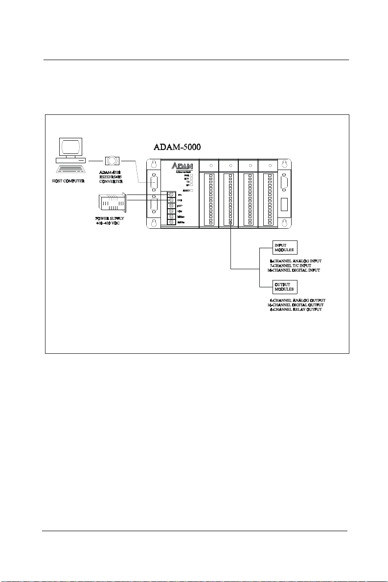
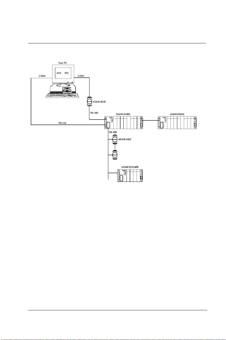
1.2 System Configuration
The following diagram shows the system configurations possible with
the ADAM-5000.
Note:
To avoid system ov er heating, only f our AD AM-5 024
are allowed to be installed on AD AM-5000E.
ADAM-5000 1-3
Page 15

Introduction
1.3 A Few Steps to a Successful System
Step 1:Review the installation Guideline
You should always make safety your first priority in any system
application. Chapter 2 provides several guidelines that will
help provide a safer, more reliable system.
Step 2: Understand the System Kernel
The system module is the heart of ADAM-5000 system. Make sure
you take time to understand the various features and setup requirements.
Step 3: Understand the I/O System Configurations
important to understand how y our I/ O m odules can be c onfigure d. It is
also important to understand how the system power budget is
calculated. This can affect your I/O configuration.
Step 4: Understand the Utility Software
Before you begin to link y our appli cations in your host computer with
the ADAM-5000 systems, it is very helpful t o understa nd how t he
DOS and Windows utility software helps you configure your
ADAM-5000.
Step 5: Review the Programming Concepts
All control systems differ in some areas. The ADAM-5000 system
allows you to develop your applications in DOS or Windows.It
provides an ASCII command set, DLL (Dynamic Library Link) and DDE
(Dynamic Data Exchange) server to you.
Step 6: Understand the Troubleshooting Procedures
Many things can be happened on the factory floor: switches fail, the
power supply is incorrect, etc. In most cases, the majority of the
troubleshooting time is spent trying to locate the problems.The
ADAM-5000 system has some built-in features that help you quickly
identify problems.
1-4 ADAM-5000
It is
Page 16

2
Installation Guideline
Page 17

Installation Guideline
2.1 General
Environmental Specifications
The following table lists the environmental specifications that general ly
2-2 ADAM-5000
apply to the ADAM-5000 system (System kernel and I/O modules).
Specification
Storage temperature -13 to 185°F (-25 to 85°C)
Ambient operating
temperature
Ambient humidity*
Atmosphere
Rating
14 to 158°F (-10 to 70°C)
5 to 95%, non-condensing
No corrosive gases
* Equipment will operate below 30% humidity. However, static
electricity problems occur much more frequently at lower humidity
levels. Make sure you take adequate precautions before you touch
the equipment. Consider using ground straps, antistatic floor
cover- ings, etc. if you use the equipment in low humidity
environments.
Power Requirements
Although the ADAM-5000 systems are designed for standard
industrial unregulated 24 V
that supplies within the range of +10 to +30V
power supply, they accept any power unit
DC
. The power supply
DC
ripple must be limited to 100 mV peak-to-peak, and the immediate ripple
voltage should be maintained between +10 and +30 V
.
DC
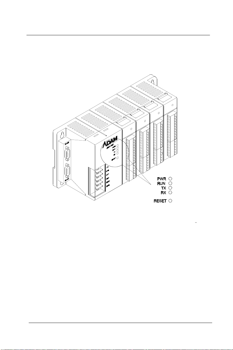
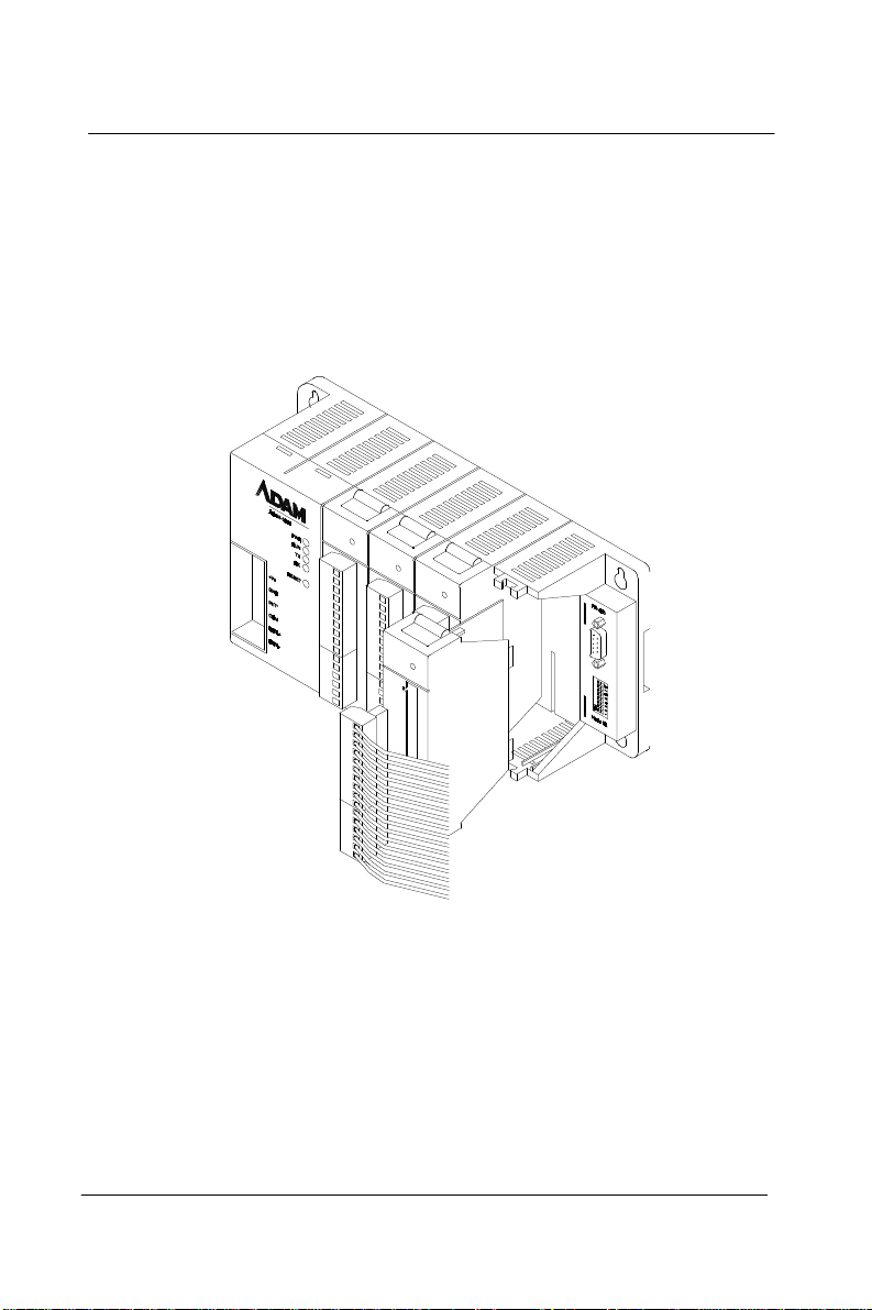
Diagnostic Indicators
Diagnostic indicators are located on the front panel of the ADAM
system. They show both normal operation and system status in your
remote I/O system. The indicators are:
•
System status (PWR, RUN)
•
Communication status (TX, RX)
•
I/O module status
Page 18
Chapter 2
A complete description of the diagnostic indicators and how to use them
for troubleshooting is e xplained in Chapter 7.
Figure 2-1 ADAM-5000 Diagnostic indicators
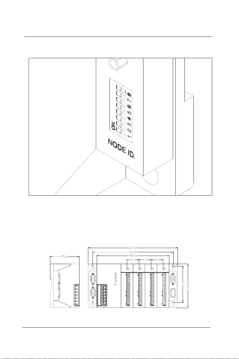
Setting the Network Address Switch
Set DIP switch 8 to OFF to install Avvantech Protocol , Set the network
address using the 8-pin DIP swi tch. Valid settings range from 0 to 127
(00h to 7Fh) where ON in any of the 8 DIP switch positions equates to a
binary 1, and OFF equates to a binary 0.
Note: 00h is special for initial setting. If 00h is setting by user, the baud
rate setting will be fixed to 9600 bps. It is recommand to setting the range
from 1 to 127 (01h to 7 Fh).
Setting the Network Address Switch
Set DIP switch 8 to ON to install Modbus function , Set the Modbus
address using the 8-pin DIP swi tch. Valid settings range from 0 to 127
(00h to 7Fh) where ON in any of the 8 DIP switch positions equates to a
binary 1, and OFF equates to a binary 0.
ADAM-5000 2-3
Page 19
Installation Guideline
Figure 2-2 ADAM-5000 Network address DIP switch
Dimensions and Weights(ADAM-5000)
The following diagrams show the dimensions of the system unit and
an I/O unit of the ADAM-5000. All dimensions are in millimeters.
2-4 ADAM-5000
Page 20
Chapter 2
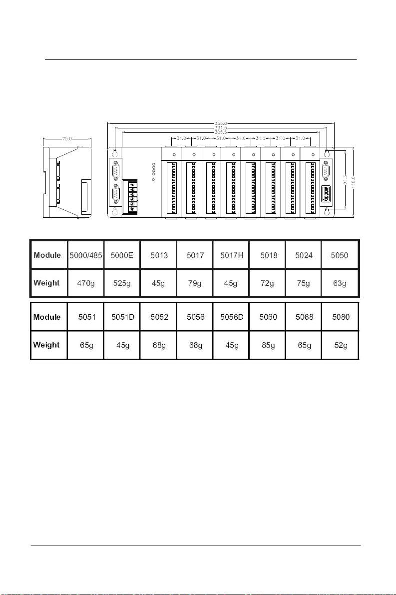
Dimensions and Weights(ADAM-5000E)
The following diagrams show the dimensions of the system unit and
the I/O unit of the ADAM-5000E. All dimensions are in millimeters.
ADAM-5000 2-5
Page 21
Installation Guideline
2.2 Module Installation
When inserting modules into the system , align t he PC board of the
module with the grooves on the top and bottom of the system. Push
the module straight into the system until it is firm ly seated in the
backplane connector. Once the module is inserted into the system, push
in the retaining clips (located at the top and bottom of the module) to
firmly secure the module to the system .
Figure 2-3 Module alignment and installation
2.3 I/O Slots and I/O channel Numbering
The ADAM-5000/485 system each provides 4 slots for use with I/O modules.
The I/O slots are numbered 0 thru 3, and the channel numbering of any I/O
module in any slot starts from 0. The ADAM-5000E system each provides 8
slots for use with I/O modules. The slots are num bered 0 thru 7 . For
example, ADAM-5017 is a 8-channel analog input module, its channel
numbering is 0 thru 7.
ADAM-5000
2-6
Page 22
2.4 Mounting
The ADAM-5000 system can be installed on a panel or DIN rail.
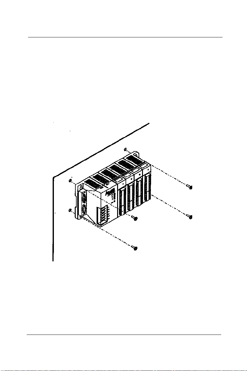
Panel Mounting
Mount the system on the panel horizontally to provide proper ventilation. You cannot mount the system vertically, upside down or on a flat
horizontal surface. A standard #7 tating screw (4mm diameter) should
be used.
Chapter 2
Figure 2-4 ADAM-5000 panel mounting
ADAM-5000 2-7
Page 23
Installation Guideline
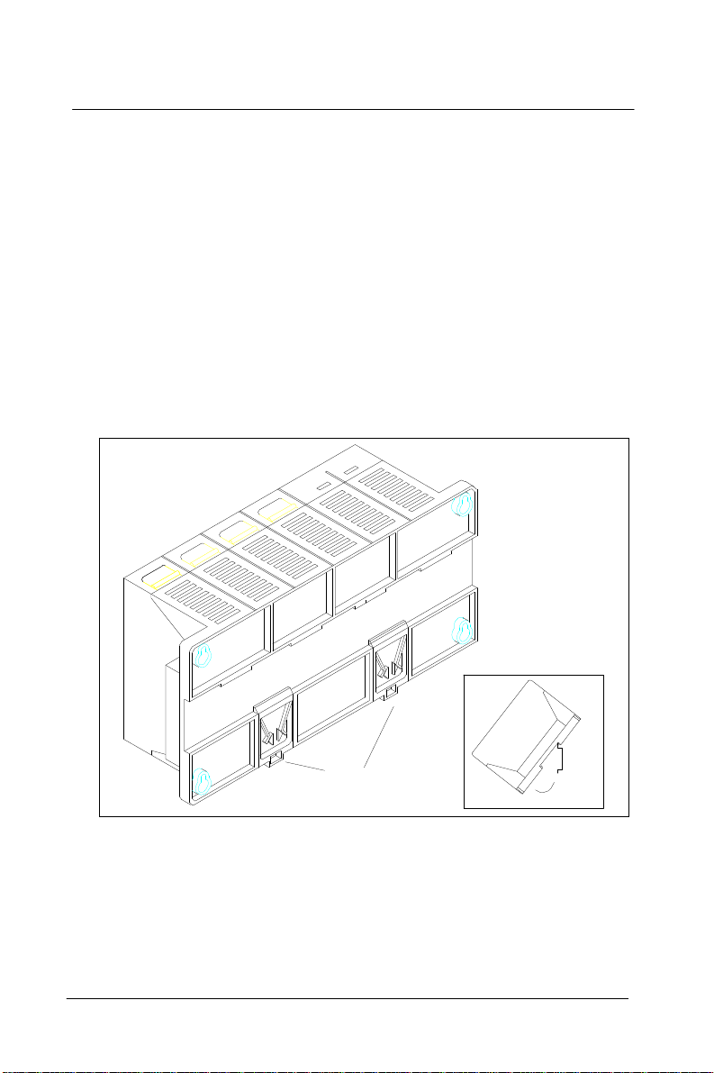
DIN Rail Mounting
The system can also be secured to the cabinet by using mounting rails.
If you mount the system on a rail, y ou sh oul d also c o nside r using e nd
brackets on each end of the rail. The end brackets help keep the system
from sliding horizontally along the rail. This helps minimize the
possibility of accidentally pulling the wiring loose. If you examine the
bottom of the system, you will notice two small retainingclips. To secure
the system to a DIN rail, place the system onto the rail and gently push
up on the retaining clips. The clips lock the system on the rail. To
remove the system, pull down on the retaining clips, lift up on the base
slightly, and pull it away from the rail.
2-8 ADAM-5000
Figure 2-5 ADAM-5000Rail mounting
Page 24
Chapter 2
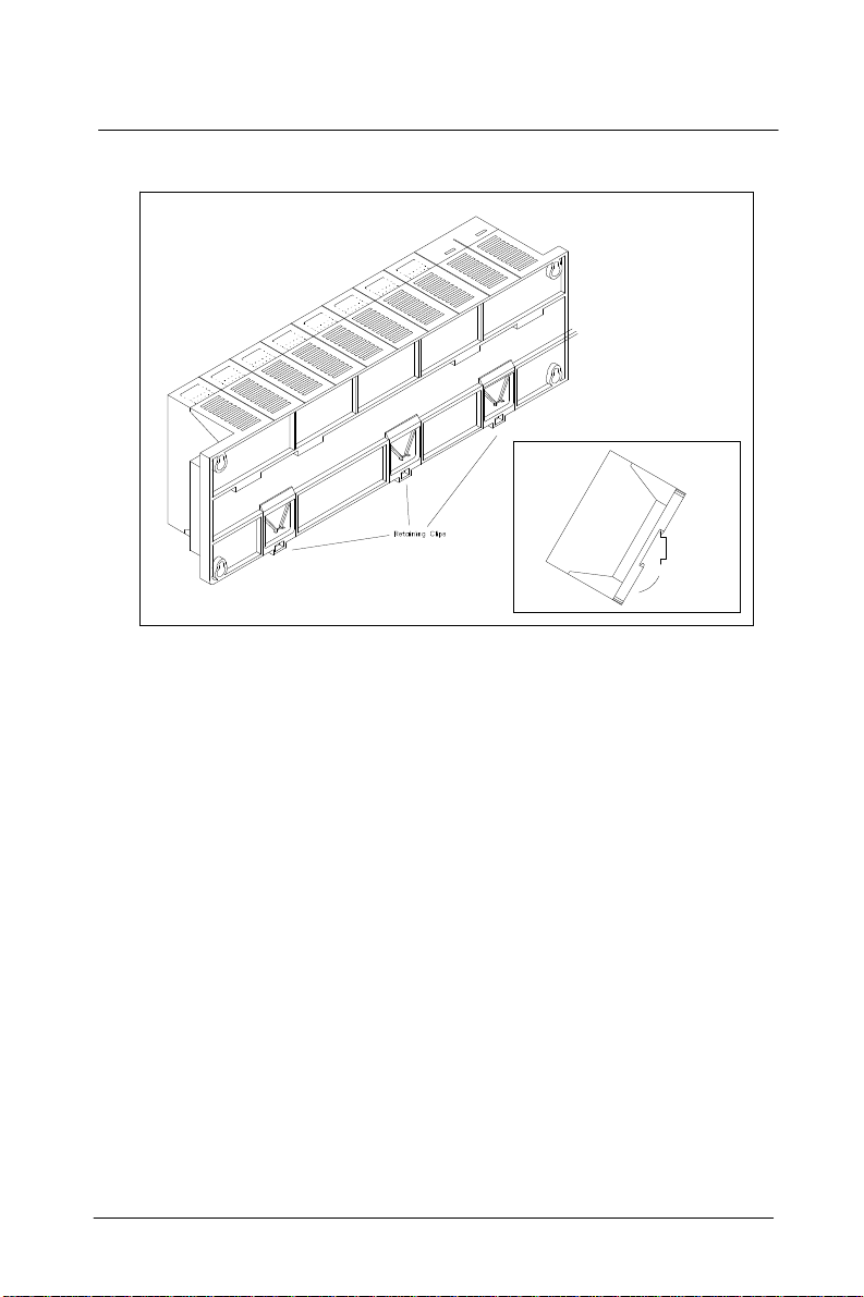
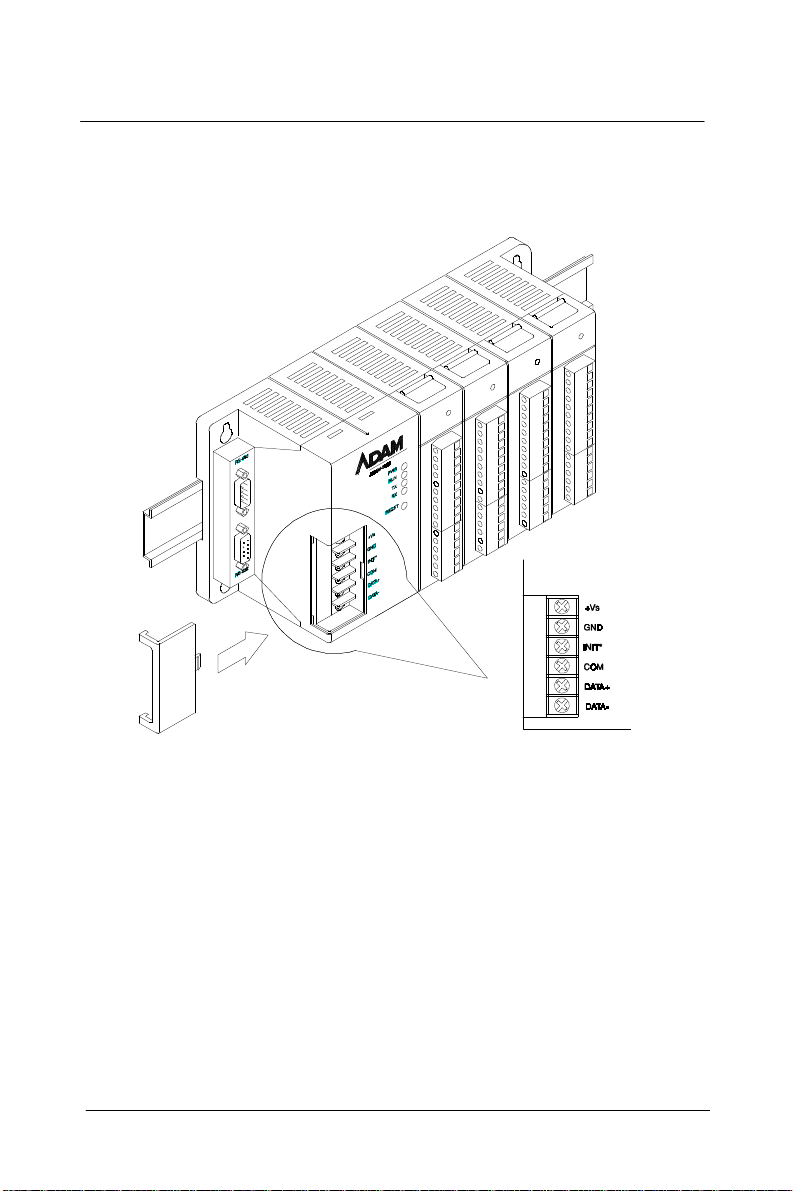
2.5 Wiring and Conections
Figure 2-6 ADAM-5000E Rail mountings
This section provides basic inform ation on wiri ng the power s upply
and I/O units, and on connecting the network.
DC Power Supply Unit Wiring
Be sure that the DC power supply voltage remains within the allowed
fluctuation range of between 10 to 30 V
for power supply wiring.
. Terminals +VS and GND are
DC
Note: The wire(s) used should be at least 2mm2.
ADAM-5000 2-9
Page 25
Installation Guideline
INIT* is used for changi ng ba ud rate an d checks um. C OM is pr ovided
as reference to the RS-485 ground signal. DATA+ and DATA- are
provided for the RS-485 twisted pair connection.
Figure 2-7 ADAM-5000 Wiring Connections
I/O Module Wiring
The system uses plug-in screw terminal blocks for the interface
between I/O module and field devices . The following inf ormation
must be considered when connecting electrical devices to I/O modules.
1. The terminal block accepts 0.5 mm2 to 2.5 mm2 wires
2. Always use a continuous length of w ire, do not co mbine wires to
attain needed length
3. Use the shortest possible wire length
4 . Use the wire trays for routing where possible
2-10 ADAM-5000
Page 26
Chapter 2
5 . Avoid running wi res near high ener gy wi ring
6 . A void running i nput wiring in close pr oximity to
output wiring where possible
7. Avoid creating sharp bends in the wires
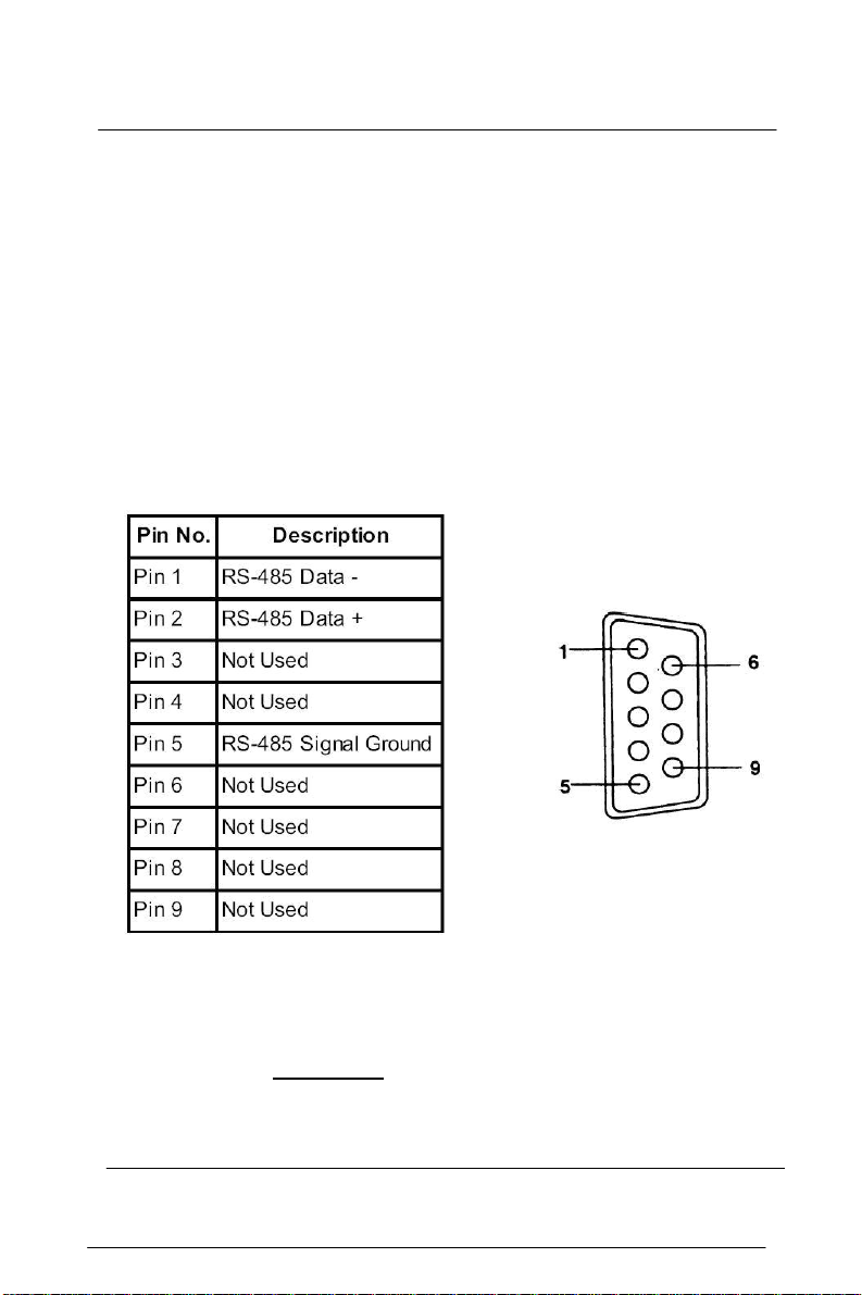
RS-485 Port Connection
There is a pair of DB9 ports in the ADAM-5000 system. The ports are
designed to link the RS-485 through a cable to a network in a system.
The pin assignment of the port is as follows:
Note:
The wiring of the RS-485 should be through a twisted
pair. To reduce electrical noise, it should be twisted
as tightly as possible
ADAM-5000 2-11
Installation Guideline
Page 27
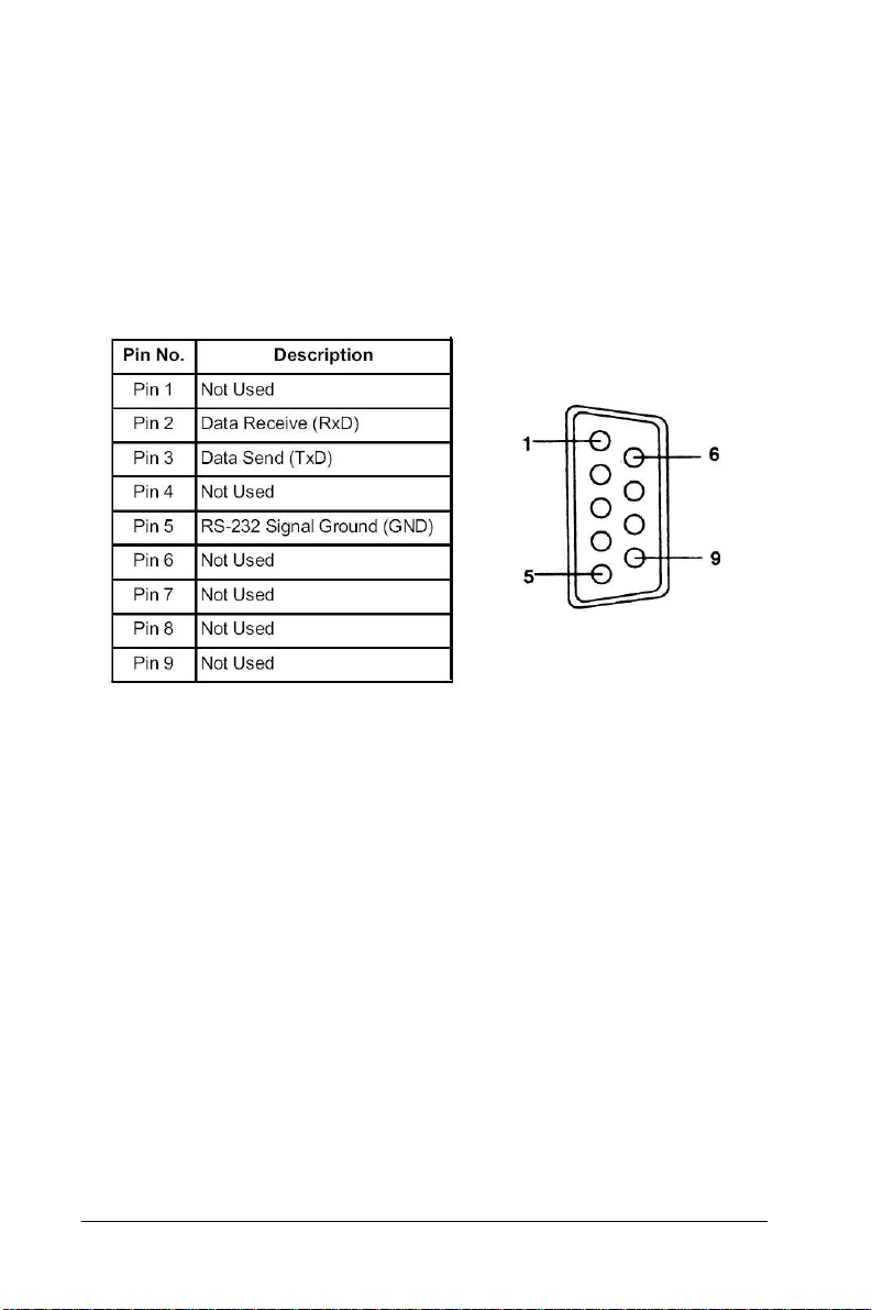
RS-232 Port Connection
The RS-232 port is designed for field configuration and diagnostics.
Users may connect a notebook PC to the RS-232 port to configure or
troubleshoot your system in the fiel d. Further , the ADAM-5000
system can also be configu red as th e slav e of the host compute r
through this port connection. The pin assignment of the port is as
follows:
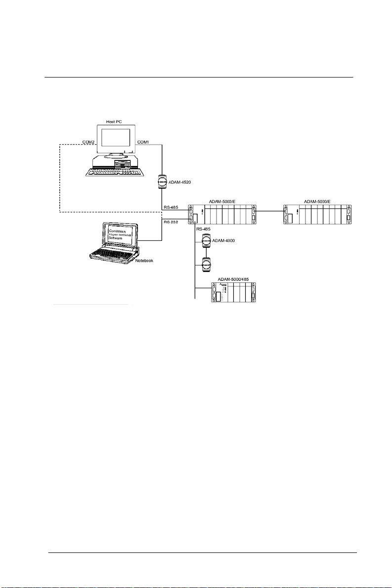
Build-in Communication Ports for Diagnostic
Connection (ADAM-5000E only)
The Built-in Communication Ports for Diagnostic Function enables
users to perform a quick diagnostics to locate where the sys tem is at
fault.
This Diagnostic Function requires the RS-485 port of ADAM-5000E
to be connected to COM1 of host PC, and the RS-23 2 port of
ADAM-5000E to COM2 of the previous host PC or othe r PCs.
Then you should install software such as ComWatch or
Hyperterminal and so on to monitor the commands that are being
issued and the subse- quent responses from connected modules.
2-12 ADAM-5000
Page 28
Chapter 2
Figure 2-8 Build-in Communication Ports for Diagnostic
Connection
Flexible Communication Port Function
Connection(ADAM-5000E only)
The Flexible Communication Port Function prevents ADAM-5000E
from system glitches due to communication line problem s.
This function enables simultaneous connections via COM1 and COM2
port of your host PC to the RS-232 and RS-485 port of ADAM-5000E
specifically. While working in conjunction with specific HMI software
(e.g. AFX, FIX) that offers COM Port Backup Function, A D AM -5000E
can circumvent failed comm unication on one port by switching t o
another available port to continue p rogram execution.
ADAM-5000 2-13
Page 29
Installation Guideline
Figure 2-9 Flexible Communication Port Function Connection
2-14 ADAM-5000
Page 30

3
ADAM-5000 System
Page 31

ADAM-5000 System
3.1 Overview
The ADAM-5000 series is a data acquisition and control system which
can control, monitor and acquire data through multichannel I/O
modules. Encased in rugged industrial grade plastic base s, the
systems provide intelligent signal conditioning, analog I/O, digital I/O,
RS-232 and RS-485 communication. The ADAM-5000/485 can handle up
to any 4 combinations of I/O m odules (64 I/O points), whi le the
ADAM-5000E can handle up to 8 combinations of I/O modules (128 I/
O points). The systems communicate with their controlling host over
a multi-drop RS-485 network.
3.2 Major Features of the ADAM-5000 System
The ADAM-5000 system consists of two m ajor pa rts: the system
kernel and I/O modules. The sy stem kernel includes a CPU c ard, power
regulator, 4-slot base, 8-slot base, bui lt-in RS-232 communication port,
and a pair of built-in RS-485 ports. It also offers the following major
features:
The CPU’s Basic Functions
The CPU is the heart of the system and has the following basic
3-2 ADAM-5000
functions:
•
Data acquisition and control for all I/O modules in the system
•
Linearization of T/C (Thermocouple)
•
Communication software and command set
•
Calibration software and command set
•
Alarm monitoring
•
Management of the EEPROM device that holds the syst em
parameters
•
Data transformation
•
Diagnosis
Page 32

Chapter 3
Diagnosis
There are 4 LEDs (indicated as PWR, RUN, TX and RX) to provide
visual information on the general operation of the ADAM-5000
system. The LEDs also indicate the error status when the
ADAM-5000 system performs the self test. Besides the LED
indica- tors, the system also offers software diagnosis via the RS232 port. For details, refer to Chapter 7.
3-Way Isolation and Watchdog Timer
Electrical noise can enter a system in many different ways. It may enter
through an I/O module, a power supply connection or the com munication ground connection. The ADAM-5000 system provides isol ation
for I/O modules (3000 V
communication power connection (3000 V
design prevents ground loops and reduces the effect of electrical
noise to the system. It also offers better surge protection to prevent
dangerous voltages or spikes from harming your system. The system
also provides a W atchdog timer to monitor the microprocessor. It will
automatically reset the microprocessor in ADAM-5000 system if the
system fails.
Remote Software Configuration and Calibration
The ADAM-5000 system merely issues a command from the host
computer, you can change an analog input module to accept several
ranges of voltage input, current i nput, the rmocouple i nput or RTD
input. With the except ion of system node address, all the param eters
including speed, parity, HI and LO al arm, and calibration parameters
setting may be set remotely. Remote configuration can be done by
using either the provided menu-based software or the command set's
configuration and calibration commands. By storing configuration
and calibration parameters in a nonvolatile EEPROM, the systems are
able to retain these parameters in case of power failure.
Flexible Alarm Setting
The ADAM-5000 system provides a flexible alarm setting method via
an utility software (ADAM.EXE) between analog input modules and
digital output modules. The user may configure a point of any
digital output module plugged into any slot as t he Hi g h alarm or Low
alarm
ADAM-5000 3-3
), communication connection (2500 VDC) and
DC
). The 3-way isolation
DC
Page 33

ADAM-5000 System
output of a channel of an anal og i nput module. The relationship
and their High/Low alarm limits may be downloaded into the
system‘s EEPROM by the host computer.
The alarm functions can be enabled or disabled rem otely. When the
alarm function is enabled, the user may select whether the digital
output is triggered. If the digital outputs are enabled, they are used
to indicate the High and Low Alarm state. The High and Low alarm
states can be read at any time by the host computer.
Every A/D conversion will be followed by a comparison with the High
and Low limit. When the input value is over the High limit or below
the Low limit, the High or Low alarm state is set to ON.
There are two alarm mode opti ons: Momentary and Latc hing.
If the alarm is in Latching mode, the alarm will stay on even when the
input value returns within limits. An alarm in Latching mode can be
turned OFF by issuing a Clear Alarm command from the host computer.
A Latching alarm is cleared by the microprocessor when the opposite
alarm is set
For example, the alarm is in latching mode and the High alarm is turned
ON. When the module receives a value that is lower tha n the Low
alarm limit, the microprocessor will clear the High alarm and turn the
Low alarm ON.
When the alarm is in Momentary mode, the alarm will be turned ON
when the input value is outside of alarm limits and OFF while the input
value remains within alarm limits. The arrangement of coupling High
and Low alarm states with digital outputs may be utilized to build ON/
OFF controllers that can operate without host computer involvement.
Connectivity and Programming
ADAM-5000 systems can connect to and communicate with all
computers and terminals. They use either RS-232 or RS-485 transmission standards and communicate with ASCII format commands.
However, users can only select and use one comm unicat ion port at
any time. All communications to and from the system are performed in
ASCII, which means that ADAM-5000 systems can be
3-4 ADAM-5000
Page 34

Chapter 3
programmed in virtually any high-level language. The details of all
commands will be covered in Chapter 6.
Flexible Communication Connection
ADAM-5000’s built-in RS-232/485 conversion capability enables users
to freely choose either RS-232 port or RS-485 port to connect with host
PC. When user select either port to connect with their host PC, the
other port could be utilized according to their specific needs.
For example, if RS-232 port is selected for connecti on with host PC,
the RS-485 port can be used for connection with DA&C module s (such
as ADAM-5000/485, ADAM-5000, ADAM-4000 modules). Thus users
save extra costs for another RS-232/4 85 conversion device (e.g.
ADAM-4520).
Or if users select RS-485 port for host PC connection, the RS-232 port
can then have different usage such as described in the following
sections (see Built-in Communication Ports for Field Diagnostics and
Flexible Communication Port)
Built-in Communication Ports for Diagnostics
(ADAM-5000E only)
When users utilize application software to control their system,
ADAM-5000E can provide anot her port to let user monitor a t any time
the communication quality and condition as a reference to maintenance and test. When er ro r o ccu r s in th e s ys tem, users can perform a
quick diagnostics to locate the fault. A consid erable am ount of
troubleshooting efforts can be saved . For e xam ple, usin g popular
ComW atch s oftware, users can watc h the current execution and
response of a certain comm and. It is very conveni ent to identi fy
whether it is communication or the hardware pr oduct that i s causing
the problem.
Flexible Communication Port(ADAM-5000E on ly )
ADAM-5000E provides a further application. Users can simultaneously connect COM1 and COM2 of host PC to RS-232 and RS-485 port of
ADAM-5000E. When host PC issues a command through one of the
COM ports but receives no response (the other port will serve as
backup), the COM Port Backup Function of HMI software (e.g. AFX,
FIX) will automatically switch to another COM port to continue
ADAM-5000 3-5
Page 35

ADAM-5000 System
program execution without undue influence on your system. Probability of a system crash has thus minimized.
3.3 System Setup
3-6 ADAM-5000
A Single System Setup thru the RS-232 Port
If users would like to use a PC to locally control and monitor a simple
application, the ADAM-5000 system provide s up to 64 points or 12 8
points and front-end wiring thro ugh the RS -232 port t o the host
computer.
A Distributed I/O Setup thru the RS-485 Network
The RS-485 network provides lower-noise sensor readings as the
systems can be placed much closer to the source. Up to 256
ADAM-5000 systems may be connected to an RS-485 multi-drop
network by using the ADAM-4510/4510S RS-485 repeaters, extending
the maximum communication distance to 4,000 ft. The host computer
is connected to the RS-485 network from one of its COM ports through
the ADAM-4520/4522 RS-232/RS-485 converter.
T o boost the network's throughput, the ADAM-4510/4510S RS-485
repeaters use a logical R TS signal to manage the re peater's direction.
Only two wires are needed for the RS-485 network: DATA+ and
DA T A-. Inexpensive, shielded twisted-pair wiring is employed.
Page 36

3.4 Technical Specification of the ADAM-5000
Processor
Communication
Chapter 3
ADAM-5000 3-7
Page 37

ADAM-5000 System
Isolation
Diagnosis
Basic Function Block Diagram
Figure 3.1 Function block diagram
3-8 ADAM-5000
Page 38

4
I/O modules
Page 39

This manual introdu ces the detail specifications function s and
application wiring of each ADAM-5000 I/O m odules. To organize an
ADAM-5510 Series Controller, you need to select I/O modules to
interface the main unit with field devices or processes that you have
previously determined. Advantech provides 19 types of ADAM5000 I/O modules for various applications so far. Following table is the
I/ O modules support list we provided f or user’s choice.
More detailed specification and user’s guides, please refer the
user’s manual of ADAM-5000 IO Module. It had integrated and
collected this information.
Module Name Specification Reference
ADAM-5013 3-ch. RTD input Isolated
ADAM-5017 8-ch. AI Isolated
Analog I/O
Digital I/O
Relay Output
Counter/Frequency ADAM-5080 4-ch. Counter/Frequency Isolated
Serial I/O ADAM-5090 4-port RS232 Non-isolated
ADAM-5000
ADAM-5017H 8-ch. High speed AI Isolated
ADAM-5017UH 8-ch. Ultra High speed AI Isolated
ADAM-5018 7-ch. Thermocouple input Isolated
ADAM-5024 4-ch. AO Isolated
ADAM-5050 7-ch. D I/O Non-isolated
ADAM-5051 16-ch. DI Non-isolated
ADAM-5051D 16-ch. DI w/LED Non-isolated
ADAM-5051S 16-ch. Isolated DI w/LED Isolated
ADAM-5052 8-ch. DI Isolated
ADAM-5055S 16-ch. Isolated DI/O w/LED Isolated
ADAM-5056 16-ch. DO Non-isolated
ADAM-5056D 16-ch. DO w/LED Non-isolated
ADAM-5056S 16-ch. Isolated DO w/LED Isolated
ADAM-5056SO 16-ch. Iso. DO w/LED (source) Isolated
ADAM-5060 6-ch. Relay output Isolated
ADAM-5068 8-ch. Relay output Isolated
ADAM-5069 8-ch. Relay output Isolated
Table 4-1: I/O M odule S up po r t Li s t
4-
2
Page 40

5
Software Utilities
Page 41

Software Utilities
There is a software utility available to the ADAM-5000 systems. The
Windows utility software helps you to configure your ADAM-5000.
A DLL (Dynamic Link Library) driver is provided to write Windows
applications, and a DDE (Dynamic Data Exchange) server is a service
that links the ADAM-5000 system s to popul ar Windows packages
such as Intouch, FIX DMACS, ONSPEC, Genesis and Excel.
5.1 ADAM-4000 and ADAM-5000 Windows Utility
The ADAM-4000 and 5000 Windows Utility offers a graphical interface
that helps you configure the ADAM-4000 and ADAM-5000 DA&C
Modules. This windows utility makes it very convenient to monitor
your Data Acquisition and Control system. The following guidelines
will give you some brief instructions on how to use the utility.
•
5-2 ADAM-5000
Overview
•
COM port settings
•
Search connected modules
•
Terminal emulation
•
Data Scope
•
Save module’ s configuration to file
•
Load module’s configuration files to configure module
•
Module configuration
•
Module calibration
•
Data input and output
•
Alarm settings
•
Download procedure
Page 42
Chapter 5
5.1.1 Overview
Main Menu
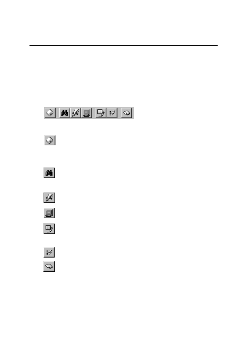
The window utility consists of a toolbar on the top and a display area
that shows forth the relevant information about the connected
modules. The utility’ s main toolbar is as shown below:
The main toolbar buttons are shortcuts to some commonly used menu
items:
Save: Saves the connected m odule t o PC.
Save the information of all connected modules to .txt file .By doing
this; users can keep track of every different setting environ ment.
Search: Search for the address of connected modules
on network.
Terminal: Issue commands and receives response.
Data Scope: Display the current data.
Save Configuration: Saves the configuration of
selected module into txt file.
Load Configuration: Download the previous configuration file
Help: Display the Online Help for the ADAM utility .
5.1.2 Save Function
Save the settings of current module (e.g. Baud rate, Address, Modules
Name) to txt file.
ADAM-5000 5-3
Page 43

Software Utilities
Example:
Figure 5-1 Display the connected module
Figure 5-2 Save the information of co nnected m odule s to txt file
5.1.3 COM Port Settings
Figure 5-3 Setup options
5-4 ADAM-5000
Page 44

Chapter 5
Baud rate:
The communication speed (baud rate) can be configured fro m 1200 bps
to 115.2 Kbps.
Prefix Char:
The Prefix Char is added to each ADAM command as follows:
[Prefix Char] + [A D AM Command]
Note:
This is a special command only for AD AM-4521,
ADAM-4541 and ADAM-4550.
Timeout:
Timeout means the time limit for waiting a response after the system
has issued a command. If no response has been received when timeout
has passed, we’ll see the “Timeout!” message on the screen.
5.1.4 Search connected modules
When you use the Search command, it will search for any connected
modules on network and di splay their dat a. T here are three ways t o
search for:
1 . Click the Toolbar button:
ADAM-5000 5-5
Page 45

Software Utilities
2 . Click the right mouse button:
3 . Click the To ols menu and choose the Search command:
4. The connected modules on netwo rk are current ly bei ng
searched:
5-6 ADAM-5000
Page 46
Chapter 5
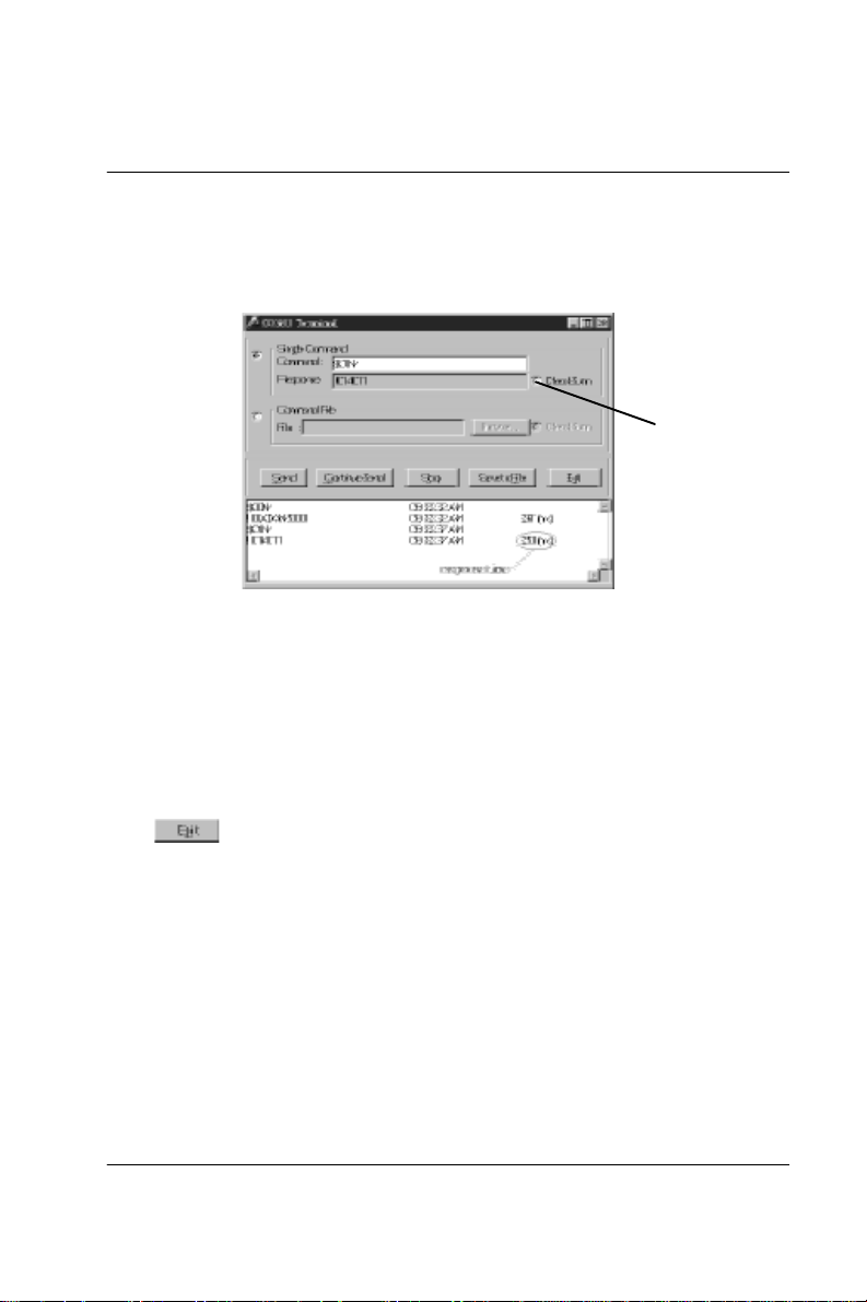
5.1.5 Terminal Emulation
You ca n issue commands and receive response by clicking the
T erminal button. There are two ways to issue commands:
1 . Issue single command:
2. Batch command
Users can compose a sequence of commands and save them into a .txt
file. Just click the Browse button to list all the .txt files available and
select the file for continuous execution of the batch of commands
therein.
3.
Back to the main menu.
Note:
If you select the checksum function on previous
main menu, you have to select the checksum
function in this menu.
ADAM-5000 5-7
Enable or
Disable
Page 47
Software Utilities
Figure 5-4 Checksum function enabled
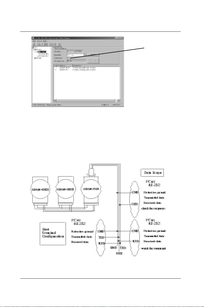
5.1.6 Data Scope
Data Scope enables you to monitor the issue of commands and the
responses on another connected PC within your system. The following example illustrates the working connection for the Data Scope
function:
Enable or
Disable
5-8 ADAM-5000
Figure 5-5 The connection for Data Scope function
Page 48

Chapter 5
When you issue commands from PC#1, you will get response.
: Send single command or batch command.
: Send a single command or batch command repeatedly.
: Stop issuing commands.
: Save history of the terminal emulation to txt file.
On PC#3, you can observe all commands issued from PC#1. Meanwhile, you can also observe all responses received at PC#2.
Figure 5-4 Checksum function enabled
ADAM-5000 5-9
Address of
selected
modules
Page 49

Software Utilities
When your system is connected with multiple ADAM-4000 or
ADAM-5000 modules, just c lick the ad dresses of t he modules t o see
relevant information (multiple selection from 00 to FF is allowed). Then
check the Filter option and click Update button to see relevant
information of the modules. Note that the information about other
unselected modules won’t show forth.
5.1.7 Saving module’s Configuration to file
•
Save the input range, baud rate, data format, checksum status
and/ or integration time and Alarm Status for a specified analog
input module.
•
Save the output range, baud rate, data format, checksum status and
slew rate for a specified analog output module.
•
Save the baud rate and checks um stat us for a digit al I/O m odule.
•
Save the input mode, baud rate, checksum status and/or frequency
gate time, input signal mode, gate m ode, alarm status, etc. for a
specified counter/frequency module.
There are three ways to save a configuration file:
1 . Click the Toolbar button
2 . Click the right mouse button
5-10 ADAM-5000
Page 50

3 . Click the Tools m enu. Choose the “Save Configuration file”
command
Chapter 5
and then specify the file name.
The configuration file is now save d.
ADAM-5000 5-11
Page 51

Software Utilities
5.1.8 Load Module’s Configuration File
•
Reload previous settings. Sets th e inpu t range, baud rate, d ata
format, checksum status and/or integration time and al arm status
for a specified analog input module.
•
Sets the output range, baud rate, data format, checksum status and
slew rate for a specified analog output module.
•
Sets the baud rate and c hecks um status for a di gital I/ O m odule.
•
Sets the input mode, baud rate, checksum status and/or frequency
gate time, input signal mode, gate m ode, alarm status, etc. for a
specified counter/frequency module.
Note:
Baud rate and checksum can only be changed i n the
INIT* state. Changed settings can only take eff ect
after a module is rebooted.
There are three ways to load a configuration file:
1 . Click the Toolbar button:
2 . Click the right mouse button:
5-12 ADAM-5000
Page 52

Chapter 5
3 . Click the T ools menu and choose Download configu ration file
to set the environment command:
4 . Choose the file name:
The configuration file is now loaded.
ADAM-5000 5-13
Page 53

Software Utilities
5.1.9 Module Configuration
•
Sets the input range, baud rate, data format, checksum status, and/
or integration time for a specified anal og input module.
•
Sets the output range, baud rate, data format, checksum status and
slew rate for a specified analog output module.
•
Sets the baud rate and checksum status for a digital I/O module.
•
Sets the input mode, baud rate, checksum status and/or frequency
gate time for a specified counter/frequency module.
Note:
Baud rate and Checksum can only be changed in the
INIT* state. Changed settings only take effect after a
module is rebooted.
For Example: The configuration of ADAM-4011
5-14 ADAM-5000
Page 54

Chapt er 5
•
Address: Represents the address of the module. The Range is from
•
Baudrate: Represents the baud rate.
•
Checksum: Represents the checksum status, i.e., Disabled/
•
Firmware V er: Represents the version of firmware.
•
Input range: Represents the input range of modules. You can refer
•
Data format: Represents the data format (e.g. engineering format).
0 to 255.
Enabled.
to Chapter 4.
Y ou can re fer to Chapter 4.
5.1.10 Module Calibration
Calibration is to adjust the accuracy of A DAM module. There are
several modes for module’ s calibration: Zero calibration and span
calibration. Only analog input and outp ut modules can be ca librated.
Note: The calibrating function supports ADAM-5013/5017/5017H/
5018/5024.
Zero Calibration:
(1). Apply power to the m odule and let it warm up for about 30 minute s.
(2). Make sure that the module is correctly i nstalled and is properly
configured for the input range you want to calibrate.
(3). Use a precision voltage so urce to apply a cal ibration volt age to t he
modules’ terminals of the specific channel.
(4). Click the “Zero Calibration” button. See Figure 5-7
5-16 ADAM-5000
Page 55

Software Utilities
Figure 5-7 Zero Calibration
(5). Click the Execute button to begin the calibration
Figure 5-8 : Execute Zero Calibration
Span Calibration:
(1). Use a precision voltage so urce to apply a cal ibration volt age to t he
modules’ terminals of the specific channel.
(2). Click the “Span Calibration” button. See Figure 5-9
Figure 5-9 : Span Calibration
5-16 ADAM-5000
Page 56

Chapter 5
(3). Click the Execute button to begin the calibration
Figure 5-10 : Execute Span Calibration
CJC Calibration:
CJC (cold junction sens or) calibration only a pplies to the ADAM-5 018
(1). Prepare a voltage source which is accurate to the mV level.
(2). Run the zero calibration and span calibration function.
(3). Use a temperature emulation device (such a s Micro-10) to se nd a
temperature signal to the ADAM module and then compare this signal
with the reading from the ADAM module. If the reading value is
different from the signal, ad just the CJC value to improve i t.
(4). Click the “CJC Calibration” button. See Figure 5-11.
Figure 5-11 : CJC Calibration
.
ADAM-5000 5-17
Page 57

Software Utilities
(5). Click the Execute button to begin the calibration
Figure 5-12 : Execute CJC Calibration
Analog Input Resistance Calibration:
R TD sensor calibratio n only applies to t he ADAM-5013
Figure 5-13 : RTD Module Calibration
.
Analog Output Calibration:
4~20 mA: ADAM 5024
Figure 5-14 : Analog Output Calibration
5-18 ADAM-5000
Page 58

5.1.11 Data Input and Output
Analog Input Module with Digital Output
•
The function can only be used when the alarm status is “Disable”.
Chapter 5
Digital Output Module
•
Click the item to turn it on or off.
Analog Output Module
ADAM-5000 5-19
Page 59

Software Utilities
•
•
Fast Decrease
Enter a valu e that u sers wan t to get
decrease
increase
•
fast increase
5-20 ADAM-5000
Page 60
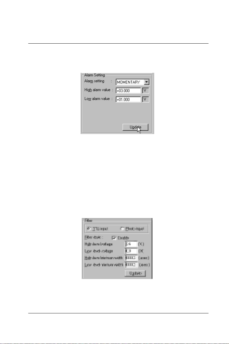
5.1.12 Alarm Setting
•
Set the alarm status, high alarm value, low alarm value, and then
click the Update button.
Chapter 5
•
Alarm setting: Disables or enables the alarm either in Latching or
Momentary mode.
•
High alarm value: Downloads the high alarm limit value into the
module. The format is always in engineering
units.
•
Low alarm value: Downloads the low alarm limit value into the
module. The format is always in engin eer ing un its.
Digital Filter
•
High level voltage: Set the high trigger level for non-isolated input
signals. The range is from 0.1 V to 5.0 V . This
high trigger level must be higher than the low
trigger level at all times.
ADAM-5000 5-19
Page 61
Software Utilities
•
Low level voltage: Set the low trigger level for non-isolated input
•
High level minimum width: Set the minimum width at hig h level.
•
Low level minimum width: Set the minimum width at low level. The
signals. The range is from 0.1 V to 5.0 V .
The unit is µsec (microseconds) and
its resolution is 1 µsec. Users can set
value from 2 to 65535.
unit is µsec (microseconds) and its
resolution is 1 µsec. Users can set
value from 2 to 65535.
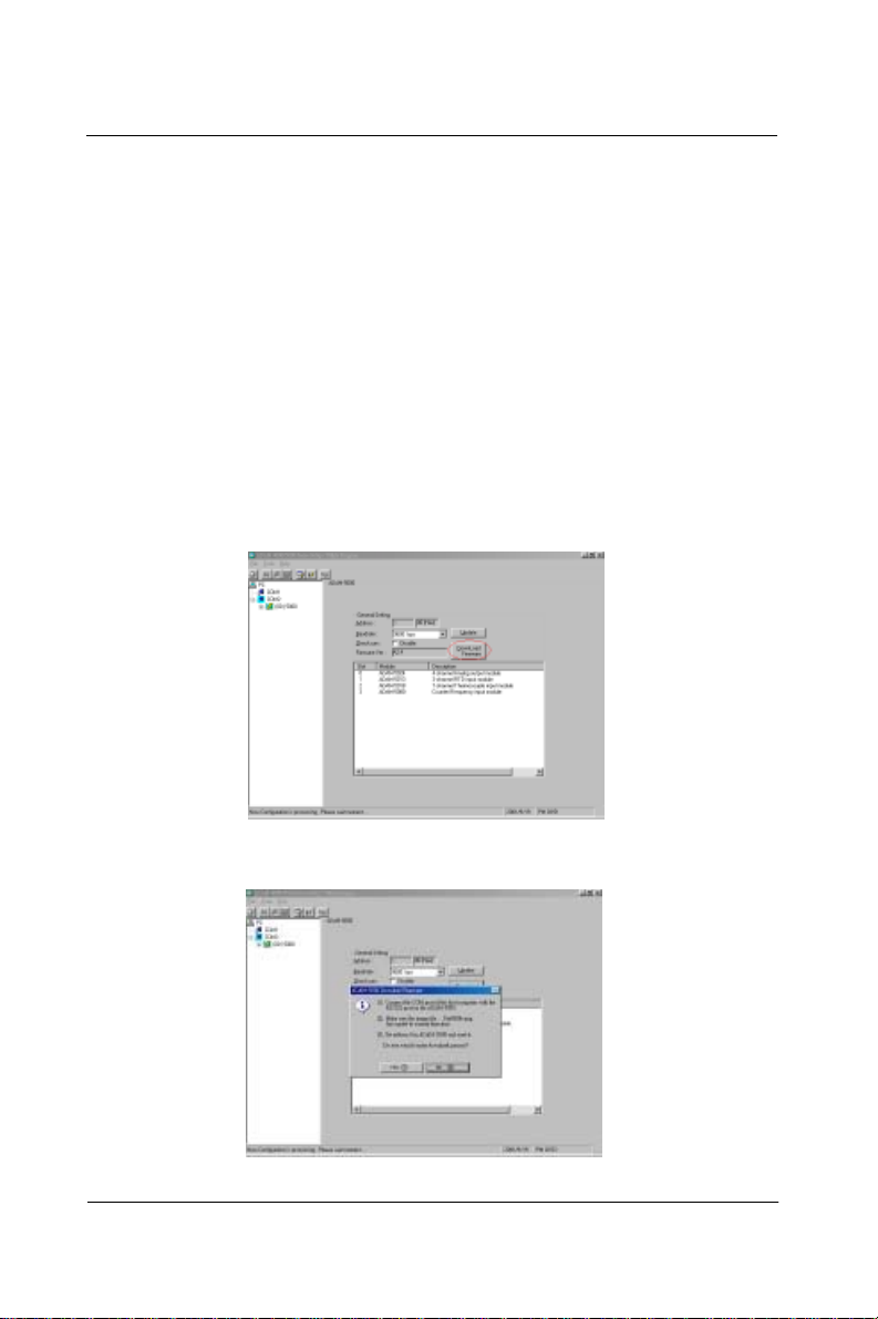
5.1.13 Download Procedure
1. Click the Download Firmware button.
2. Click Yes.
5-22 ADAM-5000
Page 62

3. Choose the b aud rate.
Chapter 5
4 . Choose Download file.
ADAM-5000 5-23
Page 63

Software Utilities
Firmware downloads in progress.
Firmware downloads complete.
NOTICE: THE FIRMWARE UPGRAD OPERATION IS ONLY
USED BY RS-232 PORT.
5-24 ADAM-5000
Page 64

Chapter 5
5.2 DLL (Dynamic Link Library) Driver
The ADAM-5000 API Dynamic Link Library (DLL) enables you
to quickly and easily write Windows applications for ADAM-
5000 systems. The library supports both C++ and Visual Basic.
Since ADAM-5000 systems communicate with a host computer
through the host‘s COM port, no additional driver (DRV or
VxD) needs to be installed. The DLL includes all necessary
function calls to utilize the ADAM-5000 systems to their fullest
extent.
T ogether with the DLL driver you‘ll find the source code of a
V isual Basic example on your diskette. The example provides
several control windows to communicate wi t h all ty pes of
ADAM-5000 m odules. You can customize the source code to
create your own tailor-made
ADAM-5000 setup program or monitoring system.
For details on the ADAM-5000 function calls refer to the
Help file included on the ADAM-5000 API diskette.
5.3 DDE (Dynamic Data Exchange) Server
The ADAM-5000 DDE server takes advantage of DDE, a built-in
Windows comm unication service. The DDE server acquires data
from the ADAM-5000 systems and passes i t t o your
application program via the hot link (DDE). The so f t w a re can
also pass control and configuration commands to the ADAM-
5000 systems using the DDE protocol. You can now use ADAM-
5000 systems wit h most W i ndows- based data acquisition
software that supports DDE. Examples include Intelluti on' s
FIX DMACS, W onderware’ s InTo uch, ONSPEC, Paragon and
Excel.
For details on the ADAM-5000 DDE server refer to the DDE
server manual for the ADAM-5000.
ADAM-5000 5-25
Page 65

Software Utilities
5-26 ADAM-5000
Page 66

6
Command Set
Page 67

Command Set
6.1 Introduction
T o a void com m unicati on conflic ts when se veral devi ces try t o send
data at the same time, all actions are instigated by the host com puter.
The basic form is a command/response protocol with the host initiating the sequence.
When systems are not transmitting they are in listen mode. The host
issues a command to a system with a specified address and waits a
certain amount of time for the syst em to resp ond. If no response
arrives, a time-out aborts the sequence and returns control to the host.
Changing ADAM-5000/5000E system's configurati on might require the
system to perform auto calibra tion bef ore change s can ta ke effect.
This is especially true when changing the range as the system has to
perform all stages of auto calibration that it performs when booted.
When this process is underway, the system does not respond to any
other commands. The command set includes information on the
delays that might occur when systems are reconfigured.
6.2 Syntax
Command Syntax: [delimiter character][address][slot][channel]
[command][data][checksum][carriage return]
Every command begins with a delimiter character. There are four valid
characters: $, #, % and @.
The delimiter character is followed by a two character address (hexadecimal) that specifies the target system. The two characters
following the address specify the module slot and channel.
Depending on the command, an optional data segment may follow the
command string. An optional two character checksum may also be
appended to the command string. Every command is terminated with
a carriage return (cr).
Note:
All commands should be issued in UPPERCASE
characters only!
6-2 ADAM-5000
Page 68

Chapter 6
The command set is divided into the follo wing five categories:
•
CPU Command Set
•
Analog Input Comm and Set
•
Analog Input Alarm Command Set
•
Analog Output Modules Command Set
•
Digital I/O Modules Command Set
Every command set category starts with a command summary of the
particular type of module, followed by datasheets that give detailed
information about individual commands.
Although commands in different subsections sometime share the same
format, the effect they have on a certain module can be completely
different than that of another. Therefore, the full command set for
each type of module is listed along with a description of the effect the
command has on the given module.
Note:
Before setting commands, the user needs to know
the type of main unit being used. If AD AM-5000/485
is being used, the "i" in Si can be set at 0 to 3 . If
ADAM-5000E is being used, the "i" in Si can be set
at 0 to 7.
This is illustrated in the table belo w:
ADAM-5000 6-3
Page 69

Command Set CPU
6.3 CPU Command Set
6-4 ADAM-5000
Page 70

Chapter 6
%aannccff
Name Configuration
Description Sets baud rate and checksum status for a specified
Syntax %aannccff(cr)
Response !aa(cr) if the command is valid.
ADAM-5000 6-5
ADAM-5000 system.
% is a delimiter character .
aa (range 00-FF) represents the 2-character hexadecimal
address of the ADAM-5000 system you want to
configure.
nn is reserved fo r system use. Its default value is 00h.
cc represents the baud rate code.
ff is a hexadecimal number that equals the 8-bit parame-
ter representing checksum stat us. The sixth bit represents the checksum status; 1 means enabled while 0
means disabled. The other bits are not used and are
set to 0.
(cr) is the terminating character, carriage return (0Dh).
?aa(cr) if an invalid parameter was entered or if the
INIT* terminal was not grounded when attempting to
change baud rate or checksum settings. There is no
response if the module detects a syntax error , com munication error or if the specified address does not exist.
! delimiter character indicating a valid command was
received.
? delimiter character indicating the command was
in- valid.
aa (range 00-FF) represents the 2-character hexadecimal
address of an ADAM-5000 system.
Page 71

Command Set CPU
%aannccff
Example command: %23000A40(cr)
Note:
(cr) is the terminating character, carriage return (0Dh).
response: !23(cr)
The ADAM-5000 system with address 23h is configured
to a baud rate of 115.2 Kbps and with checksum generation or validation.
The response indicates that the command was
received. Wait 7 seconds to let the new configuration
setting take effect before issuing a new command to the
system.
All configuration parameters can be changed dynamically , e xcept chec ksum and baud rate pa rameters.
They can only be altered when the INIT* terminal is
grounded.
6-6 ADAM-5000
Figure 6-1 Baud rate codes
Page 72

Chapter 6
$aa2
Name Conf igu ration Statu s
Description Returns the configuration status for a specified system
Syntax $aa2(cr)
Response !aaccff(cr) if the command is valid.
ADAM-5000 6-7
module.
$ is a delimiter character.
aa (range 00-FF) represents the 2-character hexadeci-
mal address of the ADAM-5000 system you want to
interrogate.
2 is the Configuration Status command.
(cr) is the terminating character, carriage return (0Dh).
?aa(cr) if an invalid operation was entered.
There is no response if the module detects a syntax
error, communication error or if the specified address
does not exist.
! delimiter character indicating a valid command was
received.
? delimiter character indicating the command was
in- valid.
aa (range 00-F F) represents the 2-character hexadecimal address of an ADAM-5000 system.
cc represents the baud rate code.
ff is a hexadecimal number that equals the 8-bit parame-
ter representing checksum stat us. The sixth bit represents the checksum status; 1 means enabled while 0
means disabled. The other bits are not used and are
set to 0.
(cr) is the terminating character, carriage return (0Dh).
Page 73

Command Set CPU
$aa2
Example command: $452(cr)
6-8 ADAM-5000
(See also the %aannccff configuration command)
response: !450600(cr)
The command requests the ADAM-5000 system at
address 45h to send its configuration status.
The ADAM-5000 system at address 45h responds with a
baud rate of 9600 bps and with no check sum function or
checksum generation.
Page 74

Chapter 6
$aaM
Name Read Module Name
Description Returns the module name from a specified ADAM-5000
Syntax $aaM(cr)
Response !aa5000(cr) if the command is valid.
ADAM-5000 6-9
system.
$ is a delimiter character.
aa (range 00-FF) represents the 2-character hexadecimal
address of the ADAM-5000 system you want to
interrogate.
M is the Module Name command.
(cr) is the terminating character, carriage return (0Dh).
?aa(cr) if an invalid operation was entered.
There is no response if the module detects a syntax
error, communication error or if the specified address
does not exist.
! delimiter character indicating a valid command was
received.
? delimiter character indicating the command was
in- valid.
aa (range 00-FF) represents the 2-character hexadecimal
address of an ADAM-5000 system.
(cr) is the terminating character, carriage return (0Dh).
Page 75

Command Set CPU
#aaF
6-10 ADAM-5000
Example command: $15M(cr)
response: !155000(cr)
The command requests the system at address 15h to
send its module name.
The system at address 15h responds with module name
5000 indicating that there is an ADAM-5000 at address
15h.
Page 76

Chapter 6
$aaF
Name Read Firmware V ersion
Description Returns the firmware version code from a specified
Syntax $aaF(cr)
Response !aa(version)(cr) if the command is valid.
ADAM-5000 6-11
ADAM-5000 system.
$ is a delimiter character.
aa (range 00-FF) represents the 2-character hexadeci-
mal address of the ADAM-5000 system you want to
interrogate.
F is the Firmware V ersion command.
(cr) is the terminating character, carriage return (0Dh).
?aa(cr) if an invalid operation was entered.
There is no response if the module detects a syntax
error, communication error or if the specified address
does not exist.
! delimiter character indicating a valid command was
received.
? delimiter character indicating the command was
in- valid.
aa (range 00-FF) represents the 2-character hexadecimal
address of an ADAM-5000 system.
(version) represents the firmware version of the ADAM5000 system.
(cr) is the terminating character, carriage return (0Dh).
Page 77

Command Set CPU
$aaF
6-12 ADAM-5000
Example command: $17F(cr)
response: !17A1.06(cr)
The command requests the system at address 17h to
send its firmware version.
The system responds with firmware version A1.06.
Page 78

Chapter 6
$aaT
Name Read I/O Type
Description Returns the I/O module no. of all slots for a specified
Syntax $aaT(cr)
Response !aabbccddee(cr) if the command is valid.
ADAM-5000 6-13
ADAM-5000 system.
$ is a delimiter character.
aa (range 00-FF) represents the 2-character hexadeci-
mal address of the ADAM-5000 system you want to
interrogate.
T is the I/O Module T y pes command.
(cr) is the terminating character, carriage return (0Dh).
?aa(cr) if an invalid operation was entered.
There is no response if the module detects a syntax
error, communication error or if the specified address
does not exist.
! delimiter character indicating a valid command was
received.
? delimiter character indicating the command was
in- valid.
aa (range 00-F F) represents the 2-character hexadecimal address of an ADAM-5000 system.
bb, cc, dd, ee represent the I/O Module No. of all slots
from slot 0 thru 3 of the ADAM-5000 system .
(cr) is the terminating character, carriage return (0Dh).
Page 79

Command Set CPU
$aaT
6-14 ADAM-5000
Example command: $12T(cr)
response: !1218245160(cr)
The command requests the ADAM-5000 system at
address 12h to send all existing I/O module numbers.
The system at address 12h responds wit h I/O m odul e
numbers 18, 24, 51 and 60 in slots 0 -3. This means
that the ADAM-5000 system contains an ADAM-5018,
ADAM-5024, ADAM-5051 and ADAM-5060 in slots 0
thru 3.
Page 80

Chapter 6
$aa5
Name Reset Status
Description Checks the reset status of the addressed ADAM-5000
system to see whether it has been reset since the last
Reset Status command was issued to the ADAM-5000
Syntax $aa5(cr)
Response !aas(cr) if the command is valid.
ADAM-5000 6-15
system.
$ is a delimiter character.
aa (range 00-FF) represents the 2-character hexadecima l
address of the ADAM-5000 system whose Reset Status
is to be returned.
5 is the Reset Status command.
(cr) is the terminating character, carriage return (0Dh)
?aa(cr) if an invalid operation was entered.
There is no response if the module detects a syntax error
or communication error or i f the specified address does
not exist.
! delimiter character indicating a valid command was
received.
? delimiter character indicating the command was
invalid.
aa (range 00-FF) represents the 2-character hexadecimal
address of an ADAM-5000 system.
s represents the Status bit that is returned by the
ADAM-5000 system. If s=1, the system has been
reset or powered up since the last time it was issued a
Reset Status command. If s=0, the system has not been
reset.
(cr) is the terminating character, carriage return (0Dh)
Page 81

Command Set CPU
$aa5
Example command: $395(cr)
response: !391(cr)
The ADAM-5000 system at address 39h was reset or
powered up since the last Reset Status command was
issued.
6-16 ADAM-5000
Page 82

Chapter 6
$aaE
ADAM-5000 6-17
Name Software Diagnostics
Description Requests the specified ADAM-5000 system to return
the error status
Syntax $aaE(cr)
$ is a delimiter character.
aa (range 00-FF) represents the 2-character hexadecimal
address of the ADAM-5000 system you want to
interrogate.
E is Software Diagnostics command.
(cr) is the terminating character, carriage return (0Dh)
Response !aabbccddee(cr) if the command is valid.
?aa(cr) if an invalid operation was entered.
There is no response if the system detects a syntax error
or communication error or i f the specified address does
not exist.
! delimiter character indicating a valid command was
received.
? delimiter character indicating the command was
invalid.
aa (range 00-FF) represents the 2-character hexadecimal
address of an ADAM-5000 system.
bbccddee are hexadecimal numbers representing the error
code from slot 0 thru slot 3 of the sy stem.
(cr) is the terminating character, carriage return (0Dh)
Page 83

Command Set CPU
Figure 6-2 Analog module erro r code s
Example: command: $01E(cr)
response: !0100000001
The command diagnoses the system at address 01h and
responds with its error status code.
The system responds that the module in slot 3 has a
span calibration error.
6-18 ADAM-5000
Page 84

Chapter 6
6.4 ADAM-5013 RTD Input Command Set
ADAM-5000 6-19
Page 85

Command Set
5013 RTD Input
Note:
The ADAM-5013 module also has "Alarm Setting"
functions. The alarm command set f o r the AD AM5013 is the same as that f or the AD AM- 5017, AD AM5017H, and the ADAM-5018. Please refer to pages
6-71 to 6-89 for this set of commands.
6-20 ADAM-5000
Page 86

Chapter 6
$aaSiArrff
Name RTD Configuration
Description Sets slot index, input range, data format and integration
time for a specified R TD input module in a specified
Syntax $aaSiArrff(cr)
Response !aa(cr) if the command is valid.
ADAM-5000 6-21
system.
$ is a delimiter character.
aa (range 00-FF) represents the 2-character hexadecimal
address of the ADAM-5000 system you want to
configure.
Si identifies the desired slot i (i:0to3).
A represents the I/O m odule c on figurat io n co m mand.
rr represents the 2-character hexadecimal code of the
input range. (See Appendix B)
ff is a hexadecimal number that equals the 8-bit parame-
ter representing data format. Bits 0 and 1 represent
data format. Bit 7 represents integration time. The
layout for the 8-bit parameter is shown in Figure 6-3
(See page 6-
38). The other bits are not used and are set to 0. (cr) i s
the terminating character, carriage return (0Dh).
?aa(cr) if an invalid operation was entered.
There is no response if the module detects a syntax error
or communication error or i f the specified address does
not exist.
! delimiter character indicating a valid command was
received.
? delimiter character indicating the command was
invalid.
aa (range 00-FF) represents the 2-character hexadecimal
Page 87

Command Set
5013 RTD Input
$aaSiArrff
Example command: $35S3A2000(cr)
address of an ADAM-5000 system.
(cr) is the terminating character, carriage return (0Dh).
response: !35(cr)
The RTD input module in slot 3 of the ADAM-5000
system at address 35h is configured to an RTD type
Pt -100 to 100° C, engineering unit data format, and
integration time 50ms (60Hz). The response indicates
6-22 ADAM-5000
that the command has been received.
Page 88

Chapter 6
$aaSiB
Name RTD Configuration Status
Description Returns the configuration parameters for a s pecified
Syntax $aaSiB(cr)
Response. !aarrff(cr) if the command is valid.
ADAM-5000 6-23
R TD input module in a specified system.
$ is a delimiter character.
aa (range 00-FF) represents the 2-character hexadecimal
address of the ADAM-5000 system you want to
interrogate.
Si identifies the desired slot i (i:0to3)
B represents the configuration status command
(cr) is the terminating character, carriage return (0Dh).
?aa(cr) if an invalid operation was entered.
There is no response if the module detects a syntax error or
communication error or if the specified address does not
exist.
! delimiter character indicating a valid command was
received.
? delimiter character indicating the command was
invalid.
aa (range 00-FF) represents the 2-character hexadecimal
address of an ADAM-5000 system.
rr represents the 2-character hexadecimal code of the
input range. (See Appendix B)
ff is a hexadecimal number that equals the 8-bit parameter
representing data format. Bits 0 and 1 represent data
format. Bit 7 represents integration time (See R TD
Configuration Command $aaSiArrff).
Page 89

Command Set
5013 RTD Input
$aaSiB
Example command: $35S3B(cr)
6-24 ADAM-5000
(cr) is the terminating character, carriage return (0Dh).
response: !352000(cr)
The R TD input module in slot 3 of the ADAM-5000
system at address 35h responds with an RTD type Pt
-100 to 100° C, engineering unit data format, and
integration time 50ms (60Hz).
Page 90

Chapter 6
$aaSi
Name All RTD Data In
Description Returns the input values of all channels of a specified
R TD input m odule in a specified syst em in engineeri ng
Syntax $aaSi(cr)
Response. >(data)(data)(data)(cr) if the command is valid.
ADAM-5000 6-25
units only.
$ is a delimiter character.
aa (range 00-FF) represents the 2-character hexadecimal
address of the ADAM-5000 system you want to
interrogate.
Si is the I/O slot of the ADAM-5000 system you want to
read.
(cr) is the terminating character, carriage return (0Dh).
?aa(cr) if an invalid operation was entered.
There is no response if the module detects a syntax error
or communication error or i f the specified address does
not exist.
> delimiter character indicating a valid command was
received.
? delimiter character indicating the command was
invalid.
aa (range 00-FF) represents the 2-character hexadecimal
address of the ADAM-5000 system.
(data) is the input value in engineering units of the
interrogated module of the specified system. The (data)
from all channels is shown in sequence from 0 to 2. If
(data)=“ ”, it means the channel is invalid.
(cr) is the terminating character, carriage return (0Dh).
Page 91

Command Set
5013 RTD Input
$aaSi
Example command: $35S3(cr)
response: >+80.01 +20.00 -40.12(cr)
The command requests the RTD input module in slot 3
of the ADAM-5000 system at address 35h to return the
6-26 ADAM-5000
input values of all channels.
The R TD input module respon ds with input values of al l
channels in sequence from 0 to 2 : +80.01° C, +20.00° C,
-40.12° C.
Page 92

Chapter 6
$aaSiCj
Name Specified RTD Data In
Description Returns the input value of a specified channel for a
specified R T D input modul e of a specified sy stem in
Syntax $aaSiCj(cr)
Response. >(data)(cr) if the comm and is valid.
ADAM-5000 6-27
engineering units only.
$ is a delimiter character.
aa (range 00-FF) represents the 2-character hexadecimal
address of the ADAM-5000 system you want to
interrogate.
SiCj identifies the desired slot i (i:0 to 3) and the desired
channel j (j:0 to 2) of the module you want to interrogate.
(cr) is the terminating character, carriage return (0Dh).
?aa(cr) if an invalid operation was entered.
There is no response if the module detects a syntax error
or communication error or i f the specified address does
not exist.
> delimiter character indicating a valid command was
received.
? delimiter character indicating the command was
invalid.
aa (range 00-FF) represents the 2-character hexadecimal
address of an ADAM-5000 system.
(data) is the input value in engineering units of the
specified channel for the specified R TD input module of
the specified system. If (data)=“ ”, it means the channel
is invalid.
(cr) is the terminating character, carriage return (0Dh).
Page 93

Command Set
5013 RTD Input
$aaSiCj
Example command: $35S3C0(cr)
response: >+80.01(cr)
The command requests the R TD input module in slot 3
of the ADAM-5000 system at address 35h to return the
input value of channel 0. T he R T D input module
responds that the input value of channel 0 is +80.01° C.
6-28 ADAM-5000
Page 94

Chapter 6
$aaSiER
Name Initialize EEPROM Data
Description Initializes all EEPROM data in a specified analog input
module to their default values. Thi s command is se nt
following a failed attempt to calibrate a module (the
module shows no effect from an at tempted calibration).
Following initialization, the problem module should
Syntax $aaSiER(cr)
Response !aa(cr) if the command is valid.
ADAM-5000 6-29
readily accept calibration.
$ is a delimiter character.
aa (range 00-FF) represents the 2-character hexadecimal
address of the ADAM-5000 system.
Si identifies the I/O slot in which you wish to initialize all
EEPROM data.
ER represents the initialize EEPROM data command.
(cr) is the terminating character, carriage return (0Dh)
?aa(cr) if an invalid operation was entered.
There is no response if the module detects a syntax error
or communication error or i f the specified address does
not exist.
! delimiter character indicating a valid command was
received.
? delimiter character indicating the command was
invalid.
aa (range 00-FF) represents the 2-character hexadecimal
address of an ADAM-5000 system.
(cr) is the terminating character, carriage return (0Dh)
Page 95

Command Set
5013 RTD Input
$aaSi5mm
Name Enable/Disable Channels for multiplexing
Description Enables/Disables multiplexing for separate channels of
the specified input module
Syntax $aaSi5mm(cr)
$ is a delimiter character.
aa (range 00-FF) represents the 2-character hexadecimal
address of the ADAM-5000 system.
Si identifies the I/O slot of the system.
5 represents the enable/disable channels command.
mm are two hexadecimal values. Each value is interpret-
ed by the module as 4 bits. The first 4-bit value is 0. The
second 4-bit value represents the status of channels 0 to
3. A value of 0 means the channel is disabled, while a
value of 1 means the channel is enabled. (See the Read
Channel Status Command $aaSi6).
Note: Bit 4 can not ena ble a channel in th e ADAM5013 since the module is physically limited to 3
(cr) is the terminating character, carriage return (0Dh)
channels.
Response !aa(cr) if the command is valid.
?aa(cr) if an invalid operation was entered.
There is no response if the module detects a syntax error
or communication error or i f the specified address does
not exist.
! delimiter character indicating a valid command was
received.
? delimiter character indicating the command was
6-30 ADAM-5000
Page 96

Chapter 6
$aaSi5mm
Example command: $00S1501(cr)
ADAM-5000 6-31
invalid.
aa (range 00-FF) represents the 2-character hexadecimal
address of an ADAM-5000 system.
(cr) is the terminating character, carriage return (0Dh)
response: !00(cr)
The command enables/disables the channels of the
analog input module in slot 1 of the system at address
00h. Hexadecimal 0 is a fixed value. Hexadecimal 1 equals
binary 0001, which enables ch annel 0 and disables channels
1 and 2.
Page 97

Command Set
$aaSi6
5013 RTD Input
Name Read Channels Status
Description Asks a specified input module to retu rn the st at us of all
channels
Syntax $aaSi6(cr)
$ is a delimiter character.
aa (range 00-FF) represents the 2-character hexadecimal
address of the ADAM-5000 system you want to
interrogate.
Si identifies the I/O slot of the system you want to read
channels status. The channel status defines whether a
channel is enabled or disabled.
6 represents the read channels status command.
(cr) is the terminating character, carriage return (0Dh)
Response !aamm(cr) if the comm and is valid.
?aa(cr) if an invalid operation was entered.
There is no response if the module detects a syntax error
or communication error or i f the specified address does
not exist.
! delimiter character indicating a valid command was
received.
? delimiter character indicating the command was
invalid.
aa (range 00-FF) represents the 2-character hexadecimal
address of an ADAM-5000 system.
mm are two hexadecimal values. Each value is interpreted as 4 bits. The first 4-bit val ue is 0. The second 4- bit
value represents the status of channels 0-3. A value of 0
means the channel is disabled, while a value of 1 means
the channel is enabled.
6-32 ADAM-5000
Page 98

Chapter 6
$aaSi6
Example command: $00S16(cr)
ADAM-5000 6-33
(cr) is the terminating character, carriage return (0Dh)
response: !0001(cr)
The command asks the analog input module in slot 1 of
the system at address 00h to send the status of its input
channels. The analog input module responds that
channel 0 of its multiplex channels is enabled, the others
are disabled (01h equals 0000 and 0001).
Page 99

Command Set
5013 RTD Input
$aaSi0
Name RTD Span Calibration
Description Calibrates a specified RTD input m odule of a specified
system to correct for gain errors.
Syntax $aaSi0(cr)
$ is a delimiter character.
aa (range 00-FF) represents the 2-character hexadecimal
address of the ADAM-5000 system which contains the
R TD module.
Si identifies the slot i (i:0 to 3) containing the R TD
module to be calibrated.
0 represents the span calibration command.
(cr) is the terminating character, carriage return (0Dh).
Response. !aa(cr) if the command is valid.
?aa(cr) if an invalid operation was entered.
There is no response if the module detects a syntax error
or communication error or i f the specified address does
not exist.
> delimiter character indicating a valid command was
received.
? delimiter character indicating the command was
invalid.
aa (range 00-FF) represents the 2-character hexadecimal
address of an ADAM-5000 system.
(cr) is the terminating character, carriage return (0Dh).
6-34 ADAM-5000
Page 100

Chapter 6
$aaSi1
Name RTD Zero Calibration
Description Calibrates a specified R TD input module of a specified
Syntax $aaSi1(cr)
Response. !aa(cr) if the command is valid.
ADAM-5000 6-35
system to correct for offset errors.
$ is a delimiter character.
aa (range 00-FF) represents the 2-character hexadecimal
address of the ADAM-5000 system which contains the
module which is to be calibrate d.
Si identifies the slot i (i:0 to 3) containing the R TD
module to be calibrated.
1 represents the zero calibration command.
(cr) is the terminating character, carriage return (0Dh).
?aa(cr) if an invalid operation was entered.
There is no response if the module detects a syntax error
or communication error or i f the specified address does
not exist.
! delimiter character indicating a valid command was
received.
? delimiter character indicating the command was
invalid.
aa (range 00-FF) represents the 2-character hexadecimal
address of an ADAM-5000 system.
(cr) is the terminating character, carriage return (0Dh).
 Loading...