

Page 1
ADVANTECH,
MODEL
MANUALLY
X-RAY
COLLIMATOR
INC.
R-72/32-A
OPERATED
45945
ADVANTECH,
TREFOIL
STERLING,
PHONE#
FAX#
703-766-4800
703-766-4801
LN.
VA
INC.
SUITE
20166
112
Page 2
Page 3
ADVANTECH,
INC.
MODEL
R72
Labels:
М)
ВБЕРАКФ............
O)
END
P)
WARRANTY:
Q)
SAFETY/RESPONSIBILITY
.4
OF
иене
LIFE
DISPOSAL.
RFIGURES,DIAGRAMS,
Diagram 1 -Electronic
Diagram 2 -Electronic
Board
Diagram
Figure
Figure
Figure
Figure
Figure
Table 1 -
Table 2 -
3—
1
2
3
4
Parts
-
5
MINIMUM
Total
Filtration
Timer
Timer
layout
Breakdown
FILTRATION
i
i
iii
TABLES..............................
LIST
OF
Board
Board,
24V
of
Primary
FM338
Eleciric
REQUIREMENT
Beam
FIGURES
in
Aluminium
AND
—
BEAM
Equivalence
DIAGRAMS
QUALITY
(AVL)
ana
ceraaaa
nana
KKK
KP
eraa
ra
KRK
M 一 1
N 一 1
O—1
cananaa
P—1
Q—2
R—1
R—6
R—7
R—8
R—I
R—2
R—3
R—4
R—5
H-]
H-2
INSTRUCTIONS
MANUAL
MTR72/DHHS
-
page
iiii
Page 4
ADVANTECH,
A)
WARNINGS
THE
COLLIMATOR
CEE
93/42,
FEDERAL
CONFORMITY
MANUAL.
THE
CAUTIONS
OF
COLLIMATOR
MANUFACTURER
ANY
VERIFY
PERFORMING A SERIES
PERFORMANCE
USE
THE
PROPER
PROBLEMS
PASSED
THE
THE
THOSE
PROCEDURES
FAILURE
USER
ASSUME
THE
REGARDING
THIS
REGULATIONS.
USER
X-RAY
COLLIMATOR.
PERSON
COMPLIANCE
IS
REQUIRED,
EQUIPMENT
INSTALLATION,
EMC
USEFUL
VICINITY
AUTHORISED
TO
OR
ASSEMBLER
FULL
INSTRUCTIONS
DOCUMENT
DESCRIBED
IEC
NORMS
IS
ENSURED
OF
THIS
CONTAINED
INSTALLATION
OF
THE
ASSEMBLING,
STANDARDS.
SUCH
WAS
OF
THE
COLLIMATOR
TESTING.
X-RAYS
UNLESS
REGARDING
FOLLOW
RESPONSIBILITY
THE
VERSION
WAS
MANUFACTURER
INC.
|
IEC
601-1,
ONLY
MANUAL
HEREIN
X-RAY
WITH
OF
DATA
LEFT
IN
OPERATION
AND
SCATTERED
ESTABLISHED
TO
OPERATE
RADIATION
THE
MANUFACTURER'S
WHICH
MANUAL
PURCHASED
TRANSLATED
FAX.
+39-039-2456958
TO
THE
HEREIN
IEC
IF
THE
IS
REQUIRED
EVEN
IF
AND
SERVICE
SYSTEM
REPAIRING
SAFETY
TESTS
INDICATING
RECORDING
WILL
DEMOSTRATE
FULL
COMPLIANCE
AND
AND
SAFE
OR
SERVICE
WILL
AFFECT
FOR
THAT
SUPPLIES
FROM
OF
THE
X-RAY
USER
IS
TO
BE
601-1-2,
COLLIMATOR
TO
THE
PERSON
IS
TO
OR
BY
RALCO
OR
REPLACING
STANDARDS
THE
DATA
MAINTENANCE
OF
THE
SURROUND
RADIATION
EXPOSURE
THE
PROTECTION..
INSTRUCTIONS,
RADIATION
PRODUCT.
INDICATIONS
IS
PROVIDED
THE
ITALIAN
COLLIMATOR
VIA
SCHIAPPARELLI
20035
LISSONE
-
OF
THIS
ISTALLED
IEC
601-1-3
READ
AND
IS
PERFECTLY
BE
PERFORMED
SRL.
COVERING
COMPLIANCE
OBTAINED
AT
LATER
WITH
THE
OF
ARE
DANGEROUS
PROCEDURES
EQUIPMENT
ON
BY
THE
VERSION,
RALCO
SRL
(MI) - ITALIA
EMAIL:
MANUAL
ON A GENERAL
AND
21
CFR
IS
INSTALLED
CAREFULLY
CONVERSANT
BY
THE
COLLIMATOR
ELECTROMEDICAL
WITH
BEFORE
TIME
THAT
STANDARDS.
THE
COLLIMATOR
EQUIPMENT
TO
ARE
MUST
OR
MODIFICATION
SAFETY,
STANDARD
DESCRIBED.
RALCO@RALCO.IT
LABEL
27/33
CAUSES
OPTIONAL
OR
ISSUED
ADDRESS
PURPOSE
SUB
AND
USED
REVIEW
PERSONNEL
INTO
21
CFR
RELEASING
ALL
TESTS
SHOULD
SINCE
BOTH
STRICTLY
BE
THOROUGHLY
THE
BY
ANNEXED
AND
MODEL
UNIT
CONFORMING
CHAPTER J OF
AS
INDICATED
THE
INSTRUCTIONS
WITH
THE
AUTHORISED
AN
X-RAY
EQUIPMENT
SUB
CHAPTER J OF
THE
COLLIMATOR
WERE
PERFORMED
EXCLUDE
RALCO
HAS
OPERATOR
OBSERVED.
FAMILIAR
OF
ANY
USER
OR
MATERIAL.
DOCUMENTATION
DISTRIBUTED
ENQUIRIES
R72
THE
CODE
IN
THIS
AND
INSTALLATION
BY
THE
SYSTEM
SUCCESSFULLY
AND
COMPONENT
ASSEMBLER
SPECIFIC
BY
TO:
MUST
AND
THE
FOR
AND
OPERATION
OTHERS
WITH
THE
DATA
RALCO
SRL
TO
OF
IN
BY
TO
INSTRUCTIONS
MANUAL
MTR72/DHHS
-
page
A—1
Page 5
ADVANTECH,
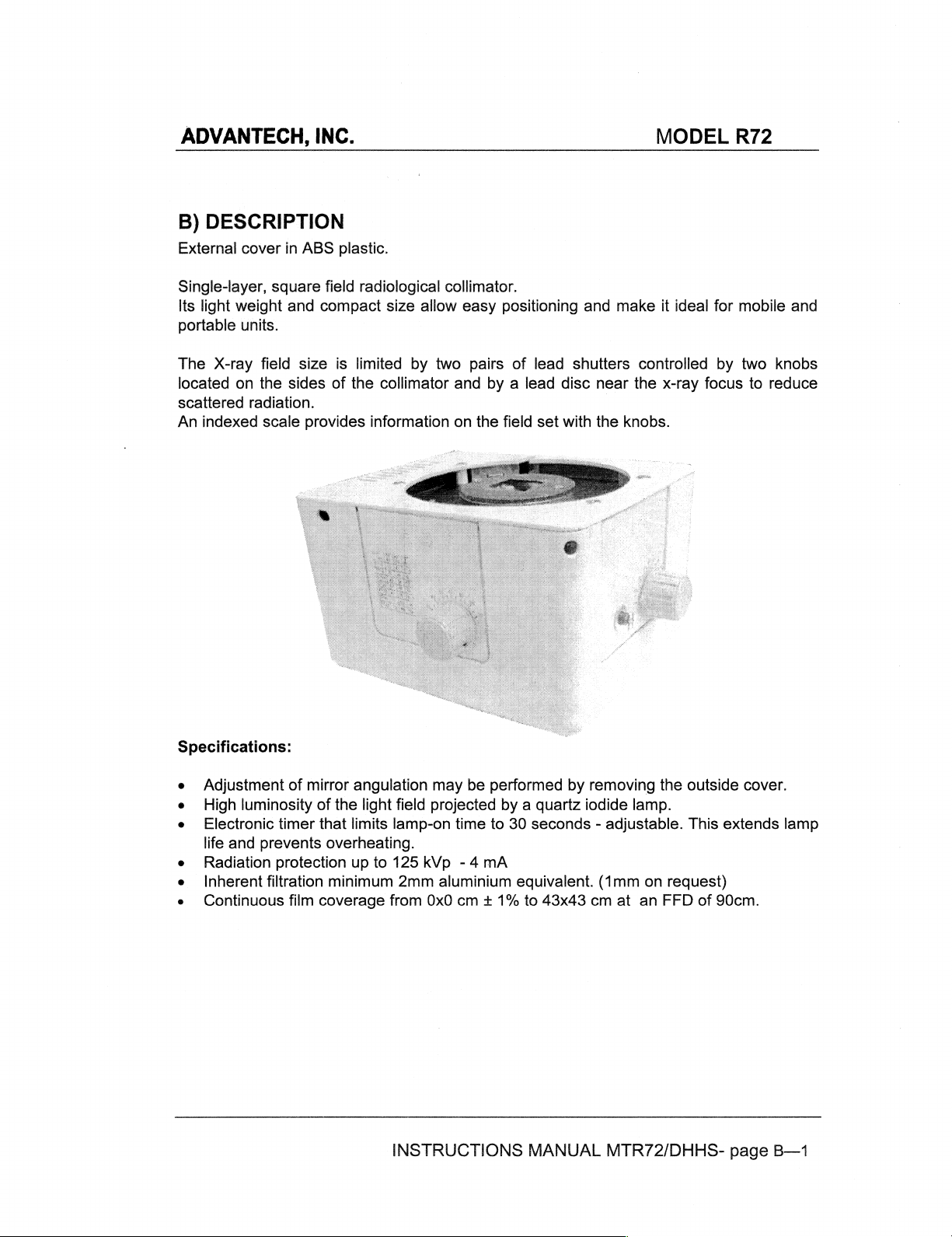
B)
DESCRIPTION
External
cover
in
INC.
ABS
plastic.
MODEL
R72
Single-layer,
Its
light
portable
The
X-ray
located
scattered
An
indexed
Specifications:
sguare
weight
units.
on
and
field
the
sides
radiation.
scale
field
radiological
compact
size
is
of
provides
size
limited
the
by
collimator
information
allow
collimator.
easy
positioning
two
pairs
and
by a lead
on
the
field
of
lead
set
and
shutters
disc
near
|
with
the
make
it
controlled
the
x-ray
knobs.
ideal
focus
for
by
mobile
two
knobs
to
reduce
and
e
Adjustment
High
e
Electronic
life
Radiation
Inherent
e
Continuous
of
luminosity
timer
and
prevents
protection
filtration
film
mirror
angulation
of
the
light field
that
limits
overheating.
up
to
minimum
coverage
may
be
projected
lamp-on
125
2mm
from
time
kVp
-4
aluminium
0x0
cm + 1%
mA
INSTRUCTIONS
performed
by a quartz
to
30
equivalent.
by
removing
iodide
seconds - adjustable.
(1mm
to
43x43
cm
MANUAL
the
outside
lamp.
This
on
request)
at
an
FFD
MTR72/DHHS-
of
90cm.
cover.
extends
page
lamp
B—1
Page 6
ADVANTECH,
INC.
MODEL
R72
Model
all
maintain
one
size
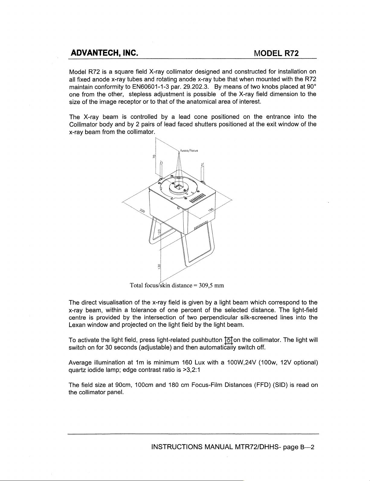
The
Collimator
x-ray
R72
fixed
from
of
the
X-ray
beam
anode
conformity
the
is a square
x-ray
other,
image
body
beam
from
receptor
is
and
the
field
X-ray
tubes
and
to
EN60601-1-3
stepless
controlled
by 2 pairs
collimator.
adjustment
or
to
collimator
rotating
that
of
anode
par.
of
the
by a lead
lead
faced
D
designed
x-ray
29.202.3.
is
possible
anatomical
cone
shutters
fuoco/focus
2!
and
constructed
tube
that
when
By
means
of
the
X-ray
area
of
interest.
positioned
positioned
of
on
at
mounted
two
knobs
field
the
the
for
installation
with
placed
dimension
entrance
exit
window
the
at
to
into
of
on
R72
90°
the
the
the
The
direct
x-ray
centre
Lexan
To
activate
switch
Average
quartz
The
field
the
collimator
visualisation
beam,
window
within a tolerance
is
provided
and
the
on
for
30
illumination
iodide
lamp;
size
at
panel.
by
projected
light
field,
seconds
at
edge
90cm,
Total
focus/
of
the
x-ray
the
intersection
on
press
(adjustable)
1m
is
minimum
contrast
100cm
o
mM
skin
distance = 309,5
field
is
of
one
percent
of
two
the
light field
light-related
and
then
160
ratio
is
>3,2:1
and
180
cm
given
by a light
of
the
perpendicular
by
the
light
pushbutton
automatically
Lux
with a 100W,24V
Focus-Film
mm
selected
beam.
Distances
beam
which
distance.
silk-screened
оп
the
switch
correspond
The
lines
collimator.
off.
(100w,
(FFD)
12V
(SID)
to
light-field
into
The
light
optional)
is
read
the
the
will
on
INSTRUCTIONS
MANUAL
MTR72/DHHS-
page
B—2
Page 7
ADVANTECH,
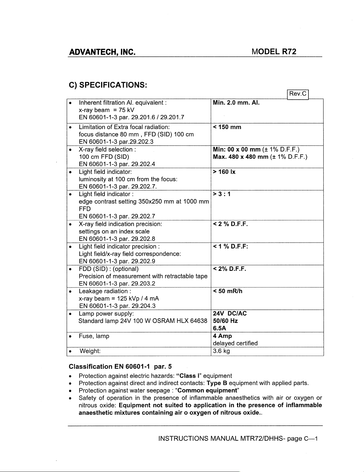
C)
SPECIFICATIONS:
e
Inherent
x-ray
beam = 75
EN
e
e
e
e
e
e
e
e
e
e
60601-1-3
Limitation
focus
distance
EN
60601-1-3
X-ray
field
100
cm
FFD
EN
60601-1-3
Light
field
luminosity
EN
60601-1-3
Light
field
edge
contrast
FFD
EN
60601-1-3
X-ray
field
settings
EN
Light
Light
EN
FDD
Precision
EN
Leakage
x-ray
EN
Lamp
Standard
Fuse,
Weight:
on
60601-1-3
field
field/x-ray
60601-1-3
(SID):
60601-1-3
beam = 125
60601-1-3
power
lamp
INC.
filtration
of
selection
indicator:
at
indicator
indication
indicator
of
radiation
lamp
Al.
kV
par.
Extra
focal
80
mm , FFD
par.29.202.3
(SID)
par.
100
cm
par.
setting
par.
an
index
par.
field
par.
(optional)
measurement
par.
:
kVp
par.
supply:
24V
equivalent
29.201.6 / 29.201.7
:
29.202.4
from
29.202.7.
:
350x250
29.202.7
precision:
scale
29.202.8
precision
correspondence:
29.202.9
29.203.2
/4
29.204.3
100 W OSRAM
:
radiation:
(SID) 100
the
focus:
mm
:
with
retractable
mA
at
HLX
cm
1000
mm
tape
64638 | 50/60
Min.
2.0
<
150
mm
Min:
00 x 00
Max.
480 x 480
>
160
Ix
>3:1
< 2 %
<1%
<
<
24V
6.5A
4
delayed
3.6
2%
50
Amp
kg
D.F.F.
D.F.F:
D.F.F.
mR/h
DC/AC
Hz
MODEL
mm.
Al.
mm
mm
certified
(+
1%
(+
R72
|
Rev.C
D.F.F.)
1%
D.F.F.)
|
Classification
Protection
Protection
Protection
Safety
nitrous
anaesthetic
of
oxide:
EN
60601-1
against
against
against
operation
electric
direct
water
Equipment
mixtures
par.
5
hazards:
and
indirect
seepage : “Common
in
the
presence
not
suited
containing
INSTRUCTIONS
“Class
air o oxygen
I?
equipment
contacts:
of
inflammable
to
application
equipment”
Type B equipment
anaesthetics
in
the
presence
of
nitrous
MANUAL
oxide..
MTR72/DHHS-
with
with
applied
air
or
of
inflammable
page
parts.
oxygen
C—1
or
Page 8
ADVANTECH,
e
Operation
See
Operation
INC.
conditions:
Instructions
Equipment
on
for
page
continuous
|—1.
operation
MODEL
at
intermittent
R72
loads
.-
Should
of
Verifications
specified
Operation
e
e
e
Included
e
e
Optional
label
data
the
non
conformity.
of
eguipment.
environment:
Ambient
Relative
Atm.
Instructions
Retractable
ROOO2:
collimator
RO
RO
e
RO
temperature = from
Humidity = from
Press. = from
with
Set
fixing
181 - Tube
198:
Focus/skin
item:
199 - tube
on
the
the
specifications
700
the
collimator
Manual
measuring
of
three
mounting
plane
distance.
port
mounting
spacer
port
mounting
collimator
are
10°C
30%
to
to
1060
:
tape
shows
spacers
fixed
to
keep
flange,
not
correspond
to
be
to
75%
hPa.
the
flange,
the
performed
40°C
Focus
Film
1.5
mm
10mm
patient
rotating
to
the
according
Distance
(0.05")
thickness.
at
30
cm.
+90°,
stop
specifications
to
(FFD - SID).
thick,
steel
at
0°,
herein,
the
Standards
(to
thickness
inform
relating
increase
10mm.
Ralco
to
focus-to-
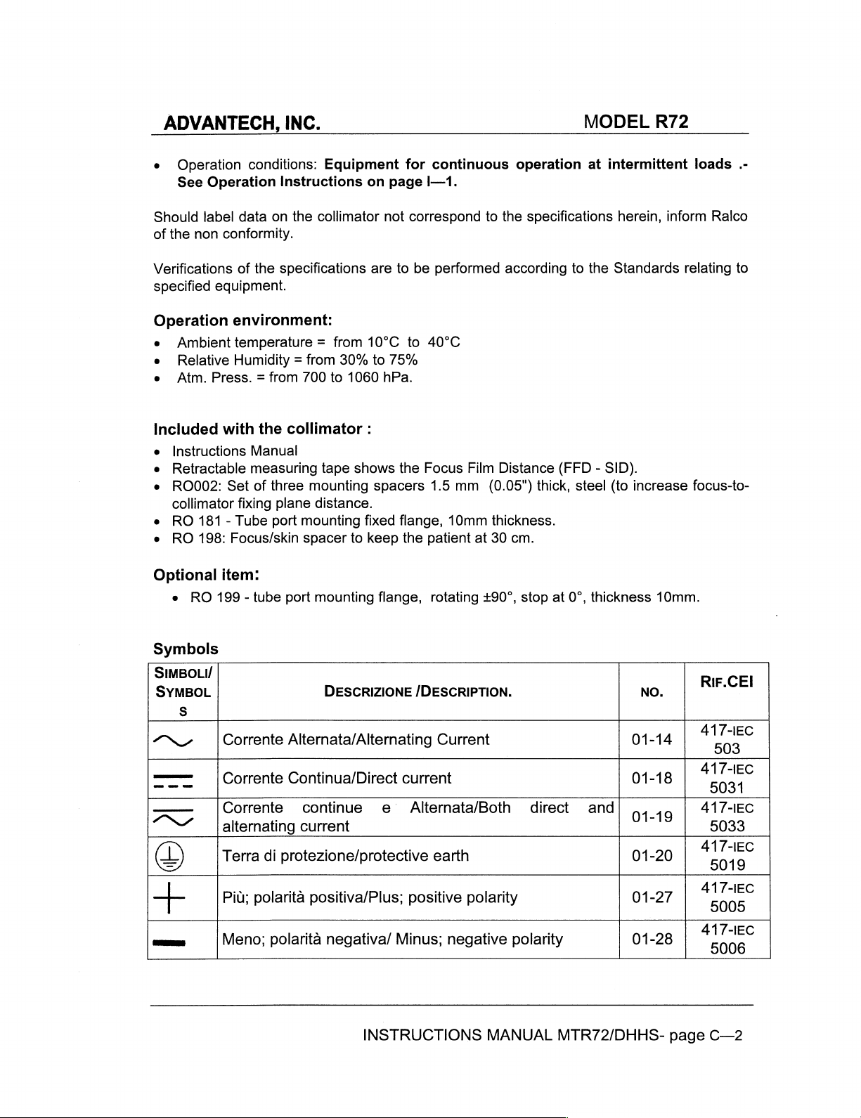
Symbols
SIMBOLI/
SYMBOL
S
O
—
———
ハン
D
十
umas
|
Corrente
|
Corrente
|Corente
l'alternating
Terra
-
Piu;
Meno;
Alternata/Alternating
Continua/Direct
continue
current
|
di
protezione/protective
a
polarita
|
polarita
DESCRIZIONE
|
, ,
positiva/Plus;
一
negativa/
INSTRUCTIONS
/DESCRIPTION.
current
e
Alternata/Both
positive
ーー
Minus;
Current
earth
polarity
negative
direct
polarity
MANUAL
01-14
01-18
and
01-19
01-20
01-27
01-28
MTR72/DHHS-
NO.
RIF.CE!
417-IEC
503
0
417-1EC
5033
417-IEC
5019
417-IEC
5005
417-IEC
5006
page
C—2
Page 9
ADVANTECH,
SIMBOLI/
SYMBOL
5
©)
(>>
|
7
INC.
DESCRIZIONE
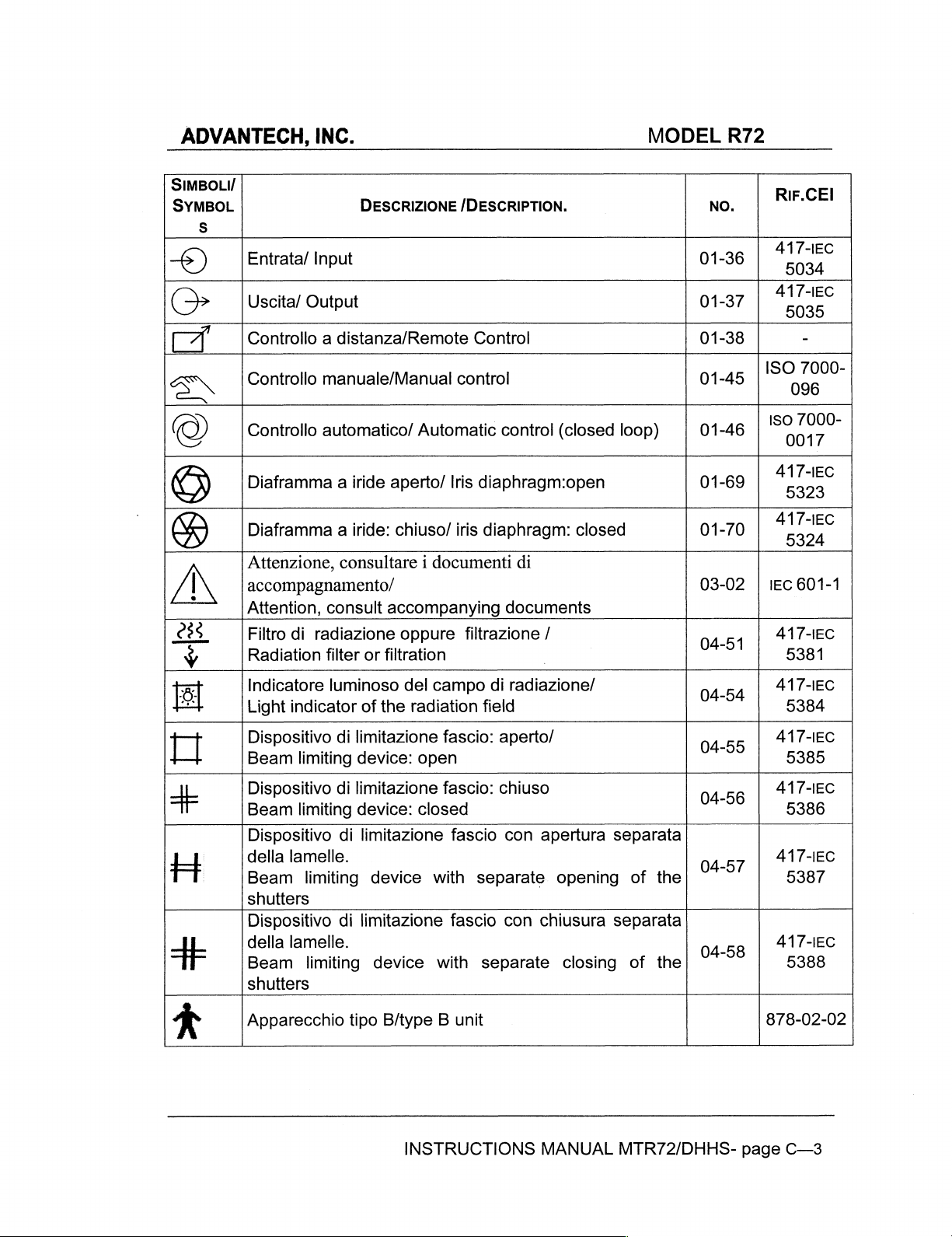
Entrata/
|Uscita/
Controllo a distanza/Remote
Input
Output
/DESCRIPTION.
Control
MODEL
R72
NO.
01-36
01-37 | "5035
01-38
RIF.CEl
417-IEC
5034
417-IEC
-
SN
©
©)
VAN
23S
Y
E.
一
十
나
H
|
Controllo
Controllo
Diaframma a iride
.
Diaframma a iride:
Attenzione,
accompagnamento/
Attention,
Filtro
Radiation
Indicatore
Light
Dispositivo
Beam
Dispositivo
Beam
Dispositivo
della
Beam
shutters
Dispositivo
della
Beam
shutters
manuale/Manual
automatico/
Lu
consultare 1 documenti
consult
di
radiazione
filter
or
luminoso
indicator
limiting
limiting
lamelle.
limiting
lamelle.
limiting
of
di
limitazione
device:
di
limitazione
device:
di
limitazione
device
di
limitazione
device
aperto/
chiuso/
accompanying
filtration
the
control
Automatic
Iris
Le
oppure
del
campo
radiation
fascio:
open 5385
fascio:
closed
fascio
with
fascio
with
control
diaphragm:open
,
iris
diaphragm:
di
documents
filtrazione
di
field
separate
separate
/
|
radiazione/
aperto/
chiuso
con
apertura
con
chiusura
(closed
|
closed
separata
opening
closing
loop)
of
separata
of
01-45
01-46
01-69
01-70
03-02 | IEC
04-51
04-54 | 41
04-55
04-56
04-57
the
04-58
the
160
417-ЕС
417-IEC
417-IEC
417-IEC
417-ЕС
417-IEC
de”
7000
~
5324
601-1
5381
MEC
5384
5386
5387
5388
+
Apparecchio
tipo
B/type B unit
INSTRUCTIONS
MANUAL
MTR72/DHHS-
878-02-02
page
C—3
Page 10
ADVANTECH,
SIMBOLI/
SYMBOL
a
4 x
INC.
DESCRIZIONE
/DESCRIPTION.
MODEL
NO.
R72
RIF.CEI
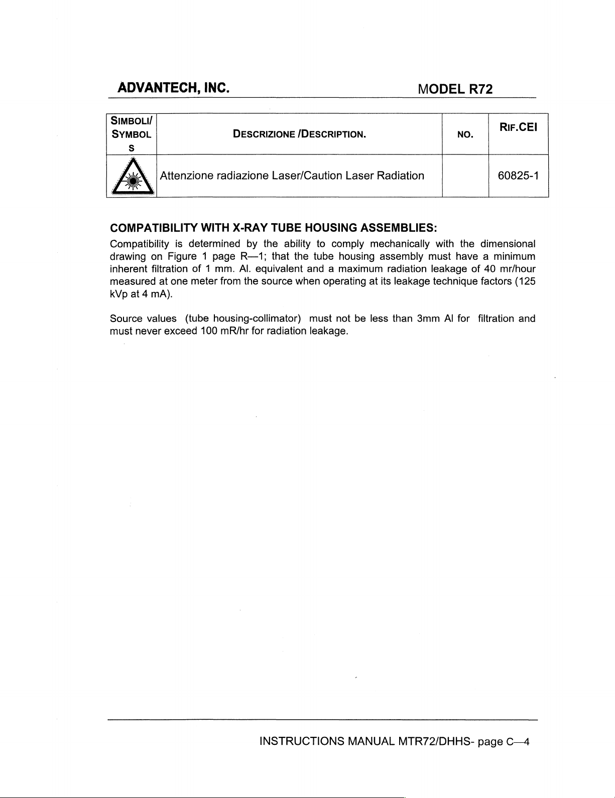
\ | Attenzione
COMPATIBILITY
Compatibility
drawing
inherent
measured
kVp
Source
must
on
filtration
at
at 4 mA).
values
never
exceed
Figure 1 page
one
WITH
is
determined
of 1 mm.
meter
(tube
100
radiazione
X-RAY
R—1;
Al.
from
housing-collimator)
mR/hr
Laser/Caution
TUBE
by
the
that
equivalent
the
source
for
radiation
ability
the
Laser
HOUSING
to
comply
tube
housing
and a maximum
when
operating
must
not
leakage.
Radiation
ASSEMBLIES:
mechanically
assembly
radiation
at
its
leakage
be
less
than
with
must
leakage
technique
3mm
Al
60825-1
the
dimensional
have a minimum
of
40
mr/hour
for
filtration
factors
(125
and
INSTRUCTIONS
MANUAL
MTR72/DHHS-
page
C—4
Page 11
ADVANTECH,
D)
MOUNTING
INC.
THE
|
COLLIMATOR
TO
THE
X-RAY
MODEL
R72
TUBE:
CAREFULLY
COLLIMATOR
IT
1.
Determine
generator
2.
Subtract
(0.05")
make
3.
The
Allowable
4.
Select
protrude
tube
5.
Remove
cover.
6.
Unscrew
tongues
Note:
exceeding
COULD
up
outer
port
when
FOLLOW
IS
CAUSE
the
distance
literature.
the
resulting
spacers
the
difference.
face
tolerance
four
countersink
through
face.
Securely
the
cover
the
four
are
withdrawn
unscrewing
0,55
Nm
CORRECTLY
THE
COLLIMATOR
distance
combined
of
the
collimator
is 1 mm.
the
flange
by
unscrewing
mounting
from
|
THE
MOUNTING
ASSEMBLED.
from
the
with
See
Figure 4 on
(0.039"). - see
bolts
of
and
bolt
the
and
the
the
Allen
WARNING
INSTRUCTIONS
TO
FALL
OR
focal
spot
from
70
mm
the
thickness
page
mounting
suitable
spacers
flange
collimator
far
to
the
the
four
centring
screws
INCORRECT
TO
OPERATE
to
the
(2,75")
of
the
R—4.
flange
Figure 4 on
thread
enough
tube
M3
screws
adjustment
top
opening;
that
AND
MOUNTING
INACCURATELY
tube
port
and
determine
mounting
must
be
page
(M6 ) and
to
engage
port
face.
located
Allen
see
control
the
MAKE SURE
COULD
face
from
flange
at
70mm
R—4
of
Figure. 1 —
from
such a length
at
least 5 threads
on
the
screws
tabs
BE
the
how
will
lower
M6
page
do
THAT
DANGEROUS:
x-ray
many
be
the
not
required
focal
that
side
until
R—1.
use
1.5
the
THE
tube
spot.
they
into
of
four
force
or
mm
to
the
the
7.
Place
collimator
Collimator
8.
Check
in
all
9.
Repeat
the
collimator
is
held
control
to
see
that
directions
the
alignment
firmly on
tabs
the
and
that
on
the
flange.
the
conform
distance
the
collimator
if
necessary.
Tighten
flange
to
EN
from
(0,55Nm
60601-1-par
the
collimator
face
is
INSTRUCTIONS
the
four
max),
see
28.4.
housing
parallel
to
MANUAL
mounting
Figure. 1 —
to
the
the
axis
MTR72/DHHS-
screws
page
mounting
of
the
table.
equally
R—1.
flange
page
until
is
equal
D—1
the
Page 12
ADVANTECH,
E)
ELECTRICAL
CHECK
ON
THE
INC.
POWER
COLLIMATOR
CONNECTION:
LABEL
THE
VERSION
MODEL
SUPPLIED.
R72
COLLIMATOR
COLLIMATOR
FUSE
CABLES
SUITABLE
ABSORPTION.
Collimator
Power
INCORRECT
SUPPLY
DIRECT
REQUIREMENTS:
AND
supply
Unscrew
Connect
e
Refer
Connect
symbol:
Remount
TO
CURRENT - IN
SUPPLY
IS
PROTECTED
TERMINALS
FOR
OPERATION
supply
connection:
the 4 screws
the
the
to
the
the
earth
由
the
cover.
POWER
THE
SUPPLY
QUARTZ
USED
must
cables
timer
cable
IODIDE
THE
IS
NOT
4A
8A
FOR
AT
conform
on
the
to
the
board
diagrams
to
the
COULD
LATTER
PROTECTED
BY
AN
DELAYED
DELAYED
THE
INTERNAL
TEMPERATURES
to
MDD
lower
portion
terminal
appropriate
DAMAGE
LAMP
AND
CASE
MAKE
WARNING
EXTERNAL
FOR
93/42
of
the
board
contacts
on
pages
contact
WARNING
THE
ELECTRONIC
TIMER
MAY
CERTAIN
BY A FUSE.
FUSE
FOR
CONNECTION
OF
cover;
R—6,
THE
THE
THE
70°
on
BE
POLARITY
PRIOR
24v
remove
+2Vcc
R—7,
the
TIMER
EITHER
VERSION
12V
VERSION
OF
C
AND
(M3)
R—8.
terminal
AND/OR
IN
CHECK
TO
CONNECTION.
THE
COLLIMATOR
COLLIMATOR
the
cover.
and
board
THE
ALTERNATE
IS
RESPECTED.
OV
THAT
(M5)
marked
LAMP.
CURRENT
THE
MUST
CURRENT
by
BE
|
the
OR
INSTRUCTIONS
MANUAL
MTR72/DHHS-
page
E—2
Page 13
ADVANTECH,
F)
COLLIMATOR
INC.
CALIBRATION:
MODEL
R72
THE
FOLLOWING
TAKE
EXPOSED
ADEQUATE
Centring
Place a 35x43
position
above
equipment
surface.
Note:
if
one
meter
one
meter
distance.
If
the
x-ray
masking
FFD
(SID)
procedures.
TO
the
the
and
FFD
and
tape,
and
PROCEDURES
PRECAUTIONS
X-RADIATION,
x-ray
with
scales
beam
etc.
field
cm.
(14x17")
x-ray
the
for
(SID)
calculate
cannot
as
required
perpendicular
REQUIRE
TO
DIRECT
with
the
light
cassette
tube/collimator
x-ray
beam
reference,
cannot
the
measurement
be
perpendicular
but
be
obtained,
oriented
to
place
relative
WARNING:
THAT
SEE
THAT
OR
INDIRECT.
field
on
the
table
assembly
measure
use
the
tolerances
vertically,
the
test
objects
to
the
x-ray
X-RADIATION
NO
PART
top
or
with
the
to
the
the
distance
obtainable
as
the
then
make
and
beam
OF
other
flat,
focal
cassette
from
FFD
ap
propriate
provision
image
as
described
BE
THE
HUMAN
horizontal
spot
at 1 meter
surface.
focal
(SID)
percentages
by
receptor
PRODUCED.
surface
Do
spot
to
that
is
using
at
the
in
the
BODY
closest
specified
following
IS
and
(40")
not
use
cassette
to
of
the
clamps,
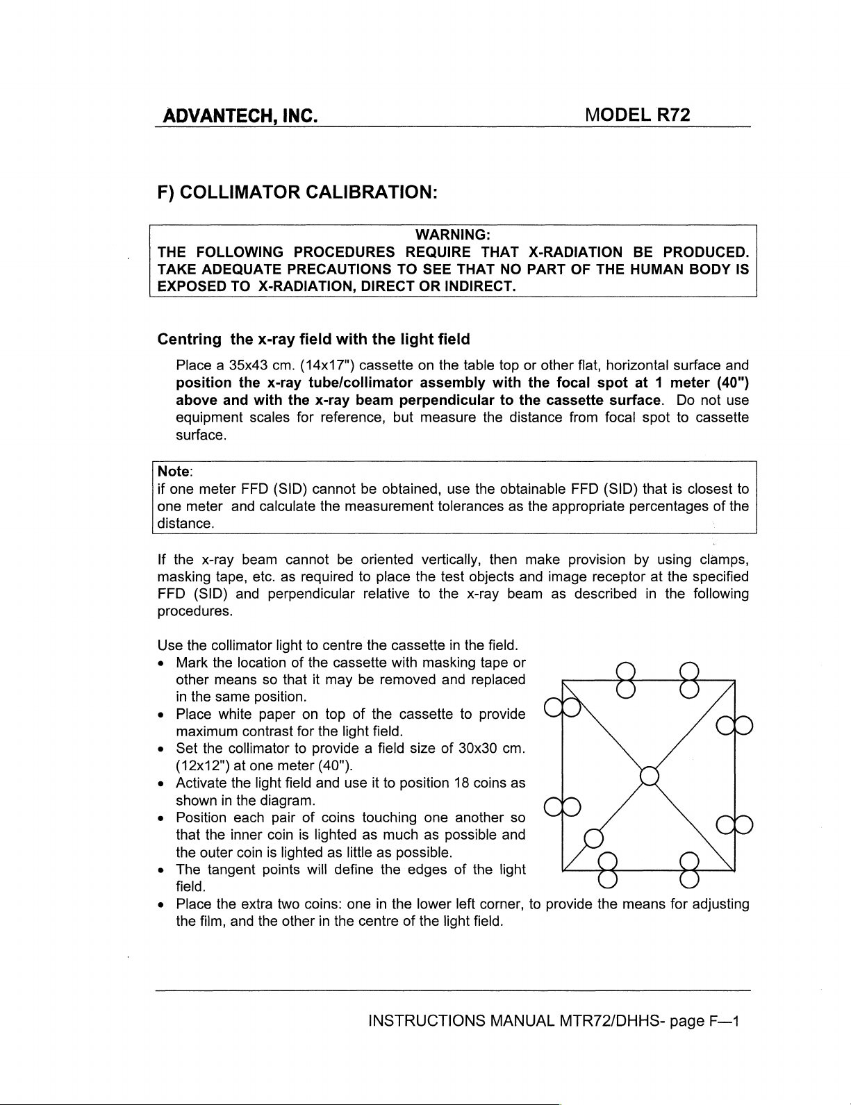
Use
Mark
other
in
Place
maximum
Set
(12x12")
Activate
shown
Position
that
the
The
field.
Place
the
the
collimator
the
means
the
same
white
the
in
the
outer
tangent
the
film,
light
location
contrast
collimator
at
the
the
each
inner
coin
extra
and
of
so
that
position.
paper
to
one
meter
light field
diagram.
pair
coin
is
lighted
points
two
the
other
to
centre
the
it
on
for
the
provide a field
(40").
and
of
coins
is
lighted
will
coins:
in
the
cassette
may
be
top
of
light
use
touching
as
as
little
define
one
the
centre
the
field.
it
INSTRUCTIONS
cassette
with
removed
cassette
size
to
position
much
as
possible.
the
edges
in
the
of
in
masking
and
of
18
one
another
as
possible
of
lower
the
light
the
tape
replaced
to
provide
30x30
coins
the
left
corner,
field.
field.
or
cm.
as
so
and
light
MANUAL
O
to
provide
MTR72/DHHS-
O,
Q
C)
©,
O
C)
O O
the
means
for
page
O
O
O
adjusting
F—1
Page 14

ADVANTECH,
e
To
find
the
determine
e
Set
the
technique
kVp, 5 mAs).
e
Make
an
exposure.
the
alignments:
centre
the
INC.
draw
centre.
factors
Remove
described
two
at
in
the
the
diagonals
x-ray
the
cassette
following
across
generator
and
process
paragraphs.
the
light
field;
to
produce a density
the
film.
MODEL
the
meeting
of
Use
the
R72
point
about 1 (about
test
film
to
check
will
50
Collimator
Inspect
field. A definitely
is
the
To
collimator
Repeat
Light
EN
60601-1-3
Misalignment
direction
If
the
test
x-ray
field
marker
to
the
one
forming
correct
in
the
NOTE:
less
sharp
corrected
will
produce
short
FFD
be
corrected
field
to
of
must
film
(shown
and,
if
Focal
four
the
the
test
The
x-ray
par
not
shows
the
Spot
images
indistinct
the
condition
direction
film
exposure
heel
effect
than
on
by
adjustment.
an
asymmetrically
(SID),
because
by
adjustment.
Field
29.202.9 - CFR
the
light
field
exceed
that
by
the
diameter
Alignment
of
the
four
edge
line,
rather
use
the
of
the
indistinct
after
will
the
other
In
of
Alignment.
to
the
2%
of
the
the
light
field
shadow
is
less
than
(Primary
collimator
indicates
than
four
making
cause
addition,
anode
21
x-ray
FFD.
of
the
that
the
mounting/centring
line.
the
three
sides . This
an
shaped
cut-off
Sub-chapter J 1020.31(d)(2)
field
In
this
(shown
collimator
20
mm
shutter
shutters
the
primary
outermost
the
adjustment.
field
toward
x-ray
tube
field
when a large
effect.
in
either
case,
by
the
shadows
shutters)
then
alignment
Cut-off).
which
shutter,
shutter.
adjustment
the
cathode
is
normal
of
12 ° or
This
is
the X (cross
it
would
to
complies
form
less
field
normal
be
less
of
the
within
the
edges
close
to
screws
to
be slightly
and
cannot
target
size
is
and
table)
or Y (long
than
markers)
the
diameter
with
the
of
the
the
focal spot,
to
shift
be
angle
used
at
may
not
20
mm
(0.78").
matches
of
regulations.
x-ray
the
table)
the
one
Greater
urged
If
misalignment
spot
requires
If
the
collimator
ο
o
o
precision
to
adjust
to
the
adjustment,
collimator
Place
cassette
Check
Using
the
x-ray
for
the
is
detected
collimator
mount
relative
the
the
the
to
test
in
the
correct
images
field,
is
possible.
greatest
mounting
repeat
spacing
the
x-ray
film
on
position
position
of
adjust
The
recommended
obtainable
in
both X and Y directions,
surface
the
test
is
correct,
tube,
but
the
face
originally
of
the
the
collimator
the
light
field
is
film
exposure
proceed
of
marked.
film
to
degree
70
mm.
but
adjustment
the
cassette
by
the
shutters
match.
INSTRUCTIONS
maximum
of
congruency.
+/- 1 mm.
after
as
follows:
shadows
as
the
MANUAL
deviation
check
that
(2.75"
the
adjustment.
is
still
over
the
cast
reference
is
one
the
spacing
+/-.039").
necessary,
white
by
the
markers.
for
the
paper
shape
MTR72/DHHS-
fourth.
from
If
the
do
not
and
and
page
You
the
focal
spacing
move
place
size
F—2
are
the
the
of
Page 15

ADVANTECH,
9
To
move
portion
permit
9
Lock
the
cover.
9
To
move
WARNING:
IT
COULD
o
DO
FINGER.
Do
not
cause
the
surface
e
Tighten
e
To
screens
required
e
Tighten
Repeat
NOT
BE
Loosen
of
the
lamp,
TOUCH
THEY
touch
the
lamp
the
adjust
to
adjustment. - See
the
the
INC.
the
light
of
the
cover
turning
DO
with
of
fixing
the
light
NOT
HOT
AND
the
two
adjust
THE
CAN
the
lamp
to
crack
alcohol,
screws
brightness
the
lamp
screws
test
exposure
field
in
the
and
remove
the
adjuster
screw
lamp-support
BE
and
field
in
the
IMMEDIATELY
CAUSE
the
lamp
LAMP,
VERY
with
and
fixing
around
holder
of
the
THE
HOT
your
possibly
then
handle
the
lamp
the
and
Figure 3 page
screens.
after
cam
to
adjustment.
cross
the
cam
and
after
long
direction,
TOUCH
SEVERE
fixing
make
SOCKET,
AND
fingers,
the
support.
edges
by
table
direction,
cover.
allow
adjusting
THE
BURNS.
screws
the
two
CAUSE
even
explode.
lamp
of
the
using
the
R—3
unscrew
Loosen
mirror
remove
and
fields
OR THE
SEVERE
when
If
with a piece
light
Allen
the
positioning,
the
mirror
the
DISSIPATOR
using
coincide
it
you
have
field,
screws
locking
cover
the
hexagonal
LAMP
BURNS.
is
cold.
touched
of
loosen
MODEL
the 4 screws
screws
(Figure 2 page
position,
and
the
dissipator
WITH
(Figure 3 —
BRACKET
Oil
paper.
move
YOUR
screw
from
the
the
screws
screen
R72
on
the
sufficiently
R—2).
and
replace
FINGERS
on
the
page
R—3)
WITH
your
skin
lamp,
wash
fixing
to
obtain
lower
to
the
side
YOUR
will
off
the
the
INSTRUCTIONS
MANUAL
MTR72/DHHS-
page
F—3
Page 16
ADVANTECH,
G)
ADJUSTMENTS
Field
Size
Indication
Regulations
use
to
state
within
2%
INC.
that
collimators
of
that
Adjustment.
must
FFD.
indicate
the
size
of
the
MODEL
x-ray
field
at
R72
the
FFD
(SID)
in
Shutter
Shutter
e
e
e
e
Crosshairs,
Dial
Pre-Adjustment:
Rotate
Use
Check
If
prove
Measure
Adjust
lf
the
the
that
the
indicators
to
Dial
the
the
reading
two
field light
each
be
correct.
Calibration:
the
x-ray
Light
is
Using a size 2 wrench,
Alignment
Activate
Turn
Check
lf
plastic
the
the
control
that
the
adjustment
panel
light-field.
lines.
e
Tighten
Friction
e
Friction
ο
lf a shutter
to
Brake
turn,
the
four
Adjustment
is
adjusted
control
adjust
Figures 3 page
control
to
ascertain
indicator
read
size
field
to
not
within
knobs
crosshair
is
required,
to
the
collimator
screws
for a shutter
is
the
R—3.
knobs
to
completely
that
is
precisely
“0”
when
the
field
shown
the
same
tolerance,
loosen
to
adjust
line
the
is
remove
and
and
replace
too
loose
appropriate
the
shutters
over
shutters
on
the
dimension
adjust
Allen
screw
the
light-field
centred
the
in
cover
position
the
movement
and
does
friction
|
close
are
the
dial line
are
test
film.
and
the
indicator
placed
to a narrow
the
narrow
and
the
cover.
force
not
hold
brake
both
sets
in
fact
closed,
read
the
on
loosen
plate
to
of
20
position,
to
obtain
of
closed.
marked
all
the
measure
.
the
line;
light
line
the
centre
Cnm.
the
shutters.
CLOSED.
other
dial
on
the
side
of
the
each
direction
in
each
four
screws
the
cross
or
is
too
tight
optimum
indications
dial.
knob.
in
turn.
direction.
securing
lines
in
the
and
is
difficult
friction - See
will
the
light
INSTRUCTIONS
MANUAL
MTR72/DHHS-
page
G—1
Page 17
ADVANTECH,
H)
COMPLIANCE
1)
MINIMUM
To
indicate
necessary
Description
availability
Standards
WARNING:
The
precautions
indirect.
The
above
in
the
compliance
for
of
of
covering
following
HVL
primary
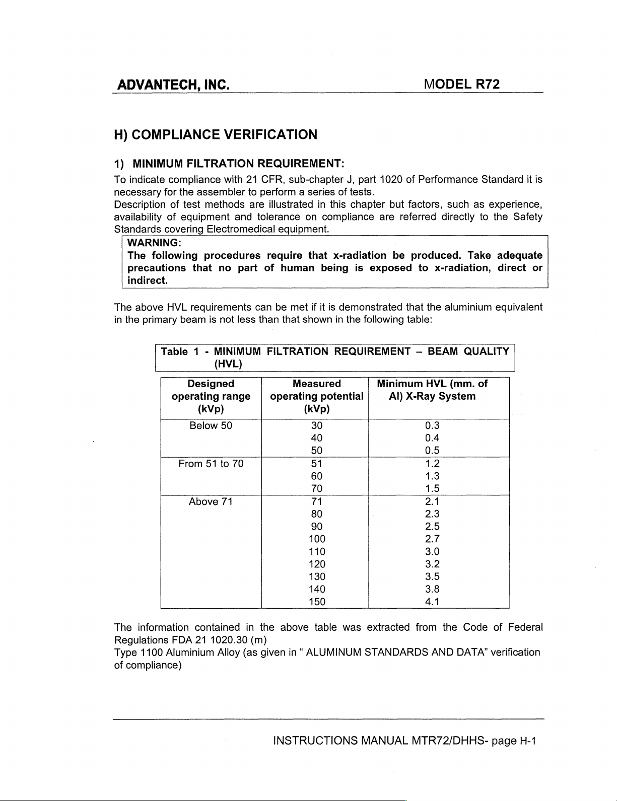
Table 1 -
operating
the
beam
From
INC.
VERIFICATION
FILTRATION
with
assembler
test
methods
equipment
Electromedical
procedures
that
no
requirements
is
not
MINIMUM
(HVL)
Designed
range
(kVp)
Below
Above
51
50
to
71
REQUIREMENT:
21
CFR,
to
perform a series
are
illustrated
and
tolerance
require
part
of
can
be
less
than
FILTRATION
operating
70
sub-chapter
in
on
equipment.
that
human
met
if
it
that
shown
Measured
(kVp)
30
40
50
51
60
70
71
80
90
100
110
120
130
140
150
J,
part
of
tests.
this
chapter
compliance
x-radiation
being
potential
is
is
demonstrated
in
the
following
REQUIREMENT
1020
but
are
referred
be
exposed
Minimum
Al)
|
MODEL
of
Performance
factors,
directly
produced.
to
x-radiation,
that
the
table:
—
BEAM
HVL
X-Ray
System
0.3
0.4
0.5
1.2
1.3
1.5
2.1
2.3
2.5
2.7
3.0
3.2
3.5
3.8
4.1
R72
Standard
such
as
to
Take
aluminium
QUALITY
(mm.
of
it
is
experience,
the
Safety
adequate
direct
equivalent
or
The
information
Regulations
Type
1100
of
compliance)
contained
FDA
21
Aluminium
1020.30
Alloy
(as
in
the
above
(m)
given
INSTRUCTIONS
table
was
in “ ALUMINUM
extracted
STANDARDS
MANUAL
from
the
Code
AND
DATA’
MTR72/DHHS-
of
Federal
verification
page
H-1
Page 18

ADVANTECH,
INC.
MODEL
R72
Visual
The
in
The
housing,
component,
the
greater
Aluminium
determination
above
the
primary
Table 2 -
Aluminium
beam
total
aluminium
than
Equivalence).
HVL
Operating
Quick-check
If
the
total
following
The
specified
and
procedures:
HVL
in
in
must
be
of
half-value
requirements
beam
is
not
less
Total
Filtration
Equivalence
Voltage
(kVp)
Below
50
From
51
to
70
Over
70
equivalence
limiting
in
the
those
of
inherent
millimetres
Table 1 (MINIMUM
greater
device
technical
equivalence
specified
minimum
filtration
of
aluminium
than
or
data
equal
layer
can
be
met
than
that
shown
of
Primary
Total
|
of
each
component
and any
attached
in
filtration
cannot
additional
in
the
the
above
requirement
be
in
the
FILTRATION
to
the
values
(hvl)
if
it
is
demonstrated
in
the
Beam
Filtration
Equivalent)
to
the
primary
Table 2 (Total
seen,
system
in
0.5
1.5
2.2
in
filtration
component
beam
then
under
REQUIREMENT
shown
that
the
following
Aluminium
Total
(mm.
Al.
the
primary
in
the
system)
or
can
be
and
make
Filtration
at a particular
the
HVL
test
in
the
table.
must
must
—
sure
be
BEAM
aluminium
Filtration
beam
measured.
is
that
of
Primary
table:
(x-ray
specified
it
kvp
be
obtained
compared
QUALITY
equivalent
tube
and
on
the
Determine
is
equal
Beam
with
the
with
those
(HVL))
or
in
a.
b.
Verify
the
radiation
Standard
The
HVL
those
illustrated
(HVL)).
equal
than
Direct
Make
window
the
that
the
instrument.
of
the
collimator
equal
distance
larger
than
an
exposure
and
time
values
Using
the
of
reading.
the
radiation read
read
absorber
determination
in
The
HVL
the
values
central
Determine
the
type
the
with
the
in
x-ray
(193
from
the
detector.
at a pre-selected
with
no
1100
collimator.
no
filtration
method
obtained
table 1 (MINIMUM
millimeters
listed
in
beam
the
mm - 7.6”).
collimator
added
Aluminium
Make
with
of
the
perpendicular
exact
filtration
an
the
2.5
in
the
from
Aluminum
above
distance
Alloy,
beam.
the
mentioned
INSTRUCTIONS
from
Place
window.
exposure
mm
FILTRATION
the
technigue
in
the
tape a total
Al
in
following
obtained
and
the
x-ray
input
Collimate
factor
beam;
using
the
the
beam
procedures
REQUIREMENT
during
table.
MANUAL
in
the
center
tube
area
of
the
beam
of
90
kVp
record
of
same
is
the
2.5
mm
technigue
greater
are
the
MTR72/DHHS-
focal
the
RAD-CHECK
and
reading.
of
or
to
—
test
must
of a RAD-Check
spot
to
the
window
to
an
area
slightly
appropriate
Aluminium
factors;
equal
be
compared
BEAM
be
to
record
to
50%
QUALITY
greater
page
at
mA
the
with
H-2
an
of
or
Page 19

ADVANTECH,
a.
DIRECT
INSTRUMENT.
WINDOW
CHECK
AN
Select a tube
filtration
sheets
filtration
filtration
Plot
C.
semilog
Verify
d.
than
AREA
the
that
the
THE
OF
AT
SLIGHTLY
in
of
to
and
exposure
paper,
values
INC.
CENTRAL
DETERMINE
THE
COLLIMATOR ( 193
AN
EQUAL
the
1100
the
record
HLV
DISTANCE
LARGER
potential
beam
Aluminium
window
the
readings
see
sample
values
shown
micro
1000
900
X-RAY
make
Gy
BEAM
THE
THAN
of
100
an
Alloy,
of
the
reading.
hereunder.
in
the
in
table 1 page
PERPENDICULAR
EXACT
(log
useful
DISTANCE
MM - 7.6”).
FROM
THE
THE
DETECTOR.
kVp
and
exposure
each
collimator.
scale)
beam
TUBE
AND
FROM
THE
PLACE
COLLIMATOR
appropriate
and
record
having a thickness
Make
versus
for
the
H-1
POTENTIAL:
WINDOW.
mA
the
an
exposure
the
total
above
100kVp - 3.8mA - 3560,
IN
THE
X-RAY
THE
and
reading.
of
added
specific
MODEL
CENTER
TUBE
FOCAL
INPUT
AREA
COLLIMATE
seconds,
Using a set
0.5
or
for
each
filtration
tube
potential
R72
OF A RAD-CHECK
SPOT
TO
OF
THE
RAD-
THE
BEAM
with
no
added
of
several
1.0
mm,
tape
increments
thickness
is
not
THE
TO
the
of
on
less
800
700
600
500
400
mm
Al
0
0.5
1
15
2
6,9
3
3,9
4
4,5
9
INSTRUCTIONS
MANUAL
MTR72/DHHS-
page
H-3
Page 20

ADVANTECH,
2)
VISUAL
Applicable
Field
3)
FIELD
Applicable
Adjustment.
4)
CROSSHAIR
Applicable
ALIGNMENTPAGE
5)
LIGHT
a)
b)
c)
d)
e)
f)
DEFINITION
Alignment.page
SIZE
Chapter: : COLLIMATOR
FIELD
When a light
cm.
cannot
Place
the
as
been
light field
Check
certain
Place a photometer
quadrants
Turn
on
previously
Verify
that
and
all
INC.
OF
X-RAY
Chapter : COLLIMATOR
F—2
INDICATION
page
G—1.
ALIGNMENT
Chapter:
be
Focus
projected.
is
larger
that
that
all
of
the
determined.
the
data
COLLIMATOR
G—1
ILLUMINATION
field
simulating
less
than : 160
of
the
X-Ray
Open
than
the
the
voltage
surfaces
the
light
light
beam
average
concerning
specified
in
capable
field.
and
illumination
the
the
measuring
the
instrument
VERSUS
CALIBRATION:
CALIBRATION:
CALIBRATION:
INTENSITY
the
X-Ray
lux
(21
CFR
tube
at
100
collimator’s
area
by
the
light
beam
of
reading
read
the
light
is
higher
and
LIGHT
field
is
used
1020.31
cm.
from
shutters
of
manufacturer
are
up
to
intensity,
the
to
the
photometer.
clean
160
lux
than
voltage
MODEL
FIELD
paragraph
paragraph
PARAGRAPH
the
illumination
(d) (2)
and
subtract
160
(ii)
the
table
assure
that
is
applied
unobstructed.
in
the
centre
lux.
Record
used.
to
2.
Field
top
each
it
the
Light
Size
2
provided
were
quadrant
to
the
of
each
ambient
the
R72
field
to
x-ray
Indication
CROSSHAIRS,
at
100
the
light field
of
the
lamp,
make
of
the
four
lighting,
measured
lux
INSTRUCTIONS
MANUAL
MTR72/DHHS-
page
H-4
Page 21

ADVANTECH,
I)
OPERATION
INC.
INSTRUCTIONS
MODEL
R72
PROLONGED
OVERHEAT
THE
OPERATOR
The
collimator
to
switch
Light
The
The
e
Supply
e
Quartz
e
Anormal
the
ON
time
factory
setting
collimators
constantly
iodide
Light/x-ray
e
The
table
is
read
by
inches
Rotate
Do
The
(vertical) - see
the
not
force
collimator
LIGHTING
IN
THE
MUST
is
normally
light
field
is
adjustable
is
has
lamp
ON/OFF
field,
setting:
on
the
crossing
knobs
the
is
WITHOUT
AREA
NEAR
THE
AVOID
OVERHEATING
SCORCH
operated
ON
from
approximately
been
designed
connected
ON
cycle
front
the
the
to
select
time
may
panel
FFD
dial
the
during
for
be
shows
on
knobs.
ready — x-rays
ALLOWING
LAMP - THE
by
15
to
30s.
to
operate
the
light
repeated
the
(SID)
page
field
at a set
may
WARNING
THE
MAXIMUM
OPERATIONS.
THE
COLLIMATOR
HIMSELF
activating
45
seconds
as
operation
field
at
twice = 1
number
in
use
(horizontal)
l—2.
FFD.
be
performed.
LAMP
TO
OR
THE
PATIENT
the
via
the
follows:
of
the
equipment.
about
minute,
to
set
COOL
CAUSES
LIMIT
ADVISED
AND
CARE
pushbutton
trimmer
30
s.
followed
with
the
with
the
THE
IS 5 SUCCESSIVE
MUST
on
on
the
by 4 minutes
knobs
index.
cassette
COLLIMATOR
BE
TAKEN
the
lateral
electronic
The
side
in
TO
LAMP
NOT
panel
board.
OFF.
number
cm
or
TO
INSTRUCTIONS
MANUAL
MTR72/DHHS-
page
I—1
Page 22

ADVANTECH,
INC.
MODEL
R72
Table
The
table
set
is
i.e.
at
be
32.
on
the
front
on
the
front
read
by
crossing
90
cm
FFD(36"
inch
cm!
5713 | 23
7718 | 32 | 29
95/24 | 43 | 39
12730)
14735 | 61
16°740|
17743 | 75 | 68
panel:
panel
shows
the
FFD-SID
SID)
and
36”
|40”
90
1100
121
53 | 48
|55
70 | 63
the
value
using
an
|72°
1180
|11.5
|16
|22
|28
|31.5
|36
|39
number
in
use
18
cm
1
to
be
with
(7")
20
.
set
with
the
cassette
cassette
q
ot
6
the
knobs.
size
size,
e
the
か
The
in
cm
field
o
A
number
on
inches.
to
be
“2°
.
set
to
be
would
INSTRUCTIONS
MANUAL
MTR72/DHHS-
page
I—2
Page 23

ADVANTECH,
J)
ROUTINE
To
ensure
regulations, a maintenance
It
is
the
constantly
Owner's
INC.
MAINTENANCE
safe
responsibility
performance
program
to
supply
is
of
the
collimator
indispensable.
or
arrange
for
and
this
its
compliance
service.
MODEL
R72
with
applicable
Cleaning
e
e
e
Recommended
Ralco
when
Re-calibration
each
performed
1.
damage.
2.
adapter
3.
recommendations
The
collimator
followed
Disconnect
Use
the
Do
following
the
substitution
Remove
Check
Check
by
non
abrasive
collimator.
no
re-apply
Maintenance
suggests a yearly
collimator
as
described
the
that
are
the
housing
the
operator.
supply
cleaning
N.B.
power
maintenance
is
subject
of
the
collimator
of
the
lower
cover
the
screws
correctly
electric
system
must
products.
the
collimator
if
inflammable
Instructions.
programme:
servicing
to
heavy
will
lamp
used
in
this
manual - page
from
and
tabs
tightened.
and
substitute
be
cleaned
Care
cover
is
liquids
programme.
workloads.
be
necessary
to
simulate
F—1.
collimator.
which
serve
parts
as
prescribed
must
be
not
watertight.
have
However
whenever
the
light
Inspect
to
secure
that
taken
leaked
field.
the
show
by
to
prevent
into
shorter
the
x-ray
Calibration
moving
the
collimator
wear.
the
sanitary
the
intervals
tube
procedures
parts
for
regulations
liquid
from
entering
collimator.
is
signs
to
the
See
are
advisable
changed
of
flange/tube
or
must
wear
the
at
be
or
4.
Check
5.
Clean
not
6.
Sparingly
7.
Wipe
8.
Remount
the
the
use
away
Lexan
collimator
abrasive
lubricate
all
excess
the
cover.
panel
and
with a soft
or
inflammable
the
moving
oil.
substitute
parts
if
cloth
paying
cleaning
using
necessary.
INSTRUCTIONS
particular
products.
graphite
MANUAL
attention
oil.
to
the
Lexan
MTR72/DHHS-
window.
page
J—1
Do
Page 24

ADVANTECH,
K)
TROUBLESHOOTING
Should
faulty
Before
following
the
Collimator
collimator
returning
problems
PROBLEM
INC.
might
the
collimator
to
cause
become
impair
the
faulty
the
to
fault
do
safety
Ralco
CAUSE
not
of
for
the
use
it
operator
repair,
until
completely
and
please
SOLUTION
patient.
make
sure
MODEL
repaired.
that
R72
it
isn't
The
use
one
of
of
the
a
The
lamp
fails
to
on
The
collimator
centred:
Incorrect
dimensions
Light
edge
not
good.
is
field
definition
switch
not
is
The
supplied
The
Timer
ON-Off
Mirrors
correctly
Knobs
Light
correctly
collimator
correctly
lamp
is
is
faulty
button
are
are
off
screen
faulty
is
not
index
not
is
not
faulty
positioned
aligned
Check
Tension/current/polarity/
Check
necessary.
See
Page
Check
no
See
Timer
Check
necessary
See
Alignment.F—2
See
page
Loosen
See
page
See
supply/
filaments - substitute
Substitution
L—1
supply
output
tension,
Substitution
on
page
contacts - substitute
Light
COLLIMATOR
F—1
knob
Field
Size
G—1
Figure 3 page
to
L—1
field
to
screws
Indication
Of
the
substitute
Of
x-ray
Fuses
The
Lamp
timer.
The
Electronic
Field
CALIBRATION:
and
R—3
if
On
If
there
is
the
timer.
if
adjust
Adjustment.
-
INSTRUCTIONS
MANUAL
MTR72/DHHS-
page
K—1
Page 25
ADVANTECH,
L)
SUBSTITUTIONS,
Substitutions:
The
following
personnel.
See
Figure 5 -
INC.
operations
Parts
Breakdown
DISASSEMBLY,
must
be
performed
on
page
R—5
TRANSPORT
by
technically
MODEL
prepared
R72
and
authorised
Substitution
WARNING:
IT
COULD
WARNING:
YOUR
Substitution
FINGER.
Disconnect
Remove
Remove
Carefully
Substitute
Make
sure
Check
If
necessary
Remount
Disconnect
Remove
Remove
Identify
Disconnect
Install
connection
DO
BE
DO
the
the
remove
on
the
the
the
the
the
of
the
lamp:
NOT
IMMEDIATELY
HOT
AND
NOT
TOUCH
THEY
supply
lower
cover
lamp
protection
the
the
lamp
that
the
pins
light
field/x-ray
remove
disconnected
of
the
electronic
supply
lower
cover.
two
screws
cables
the
new
of
cables
timer
the
cables
and
CAUSE
CAN
faulty
with
are
the
their
from
by
SEVERE
THE
LAMP,
BE
VERY
dissipator.
lamp.
an
identical
completely
field
correspondence
lamp,
rotate
items
timer
holding
proceeding
to
the
position
the
terminal
the
4-way
TOUCH
HOT
lamp
electronic
on
THE
BURNS.
THE
AND
(same
inserted
it
180°
the
board.
in a reverse
terminal
DISSIPATOR
SOCKET,
CAUSE
V, W and
in
the
axially
terminal
and
timer.
order;
board.
OR
THE
SEVERE
filament
lampholder
re-insert.
board.
pay
WITH
particular
YOUR
LAMP
BURNS.
power)
BRACKET
attention
FINGURES
WITH
to
the
Disassembly
e
Disconnect
e
Disconnect
e
Loosen
to
let
the
supply
the
the 4 fixing
collimator
to
supply
the
collimator.
cables.
screws
fall.
on
the
upper
INSTRUCTIONS
part
of
the
collimator - care
MANUAL
must
MTR72/DHHS-
be
page
taken
L—1
not
Page 26

ADVANTECH,
INC.
MODEL
R72
Transport
Suitable
e
Place
collimator.
e
Use
an
collimator
shipment
e
Limit
Ambient
Relative
Atm.
當
/
/
v
и
UMIDITÀ
and
storage:
packing
the
appropriate
from
or
Storage
must
collimator
box
rough
storage.
conditions:
Temperature = from
Humidity = from
Pressure = from
a
Ny
+
\
\
い
…
1)
RH<95%
V7
be
provided
in a plastic
for
transport,
handling.
This
-40°C
10%
to
95%
500 a 1060
FRAGILE
for
bag
will
to
hPa.
the
collimator.
to
avoid
shipment
avoid
+70°C
packing
or
damage
material
storage
to
the
from
taking
care
collimator
entering
to
protect
during
the
the
transport
INSTRUCTIONS
MANUAL
MTR72/DHHS-
page
L—2
Page 27

ADVANTECH,
M)
SPARE
NOTE:
SERIAL
WHEN
NUMBER
RO
002 | STEEL
RO
181 | MOUNTING
RO
198 | FOCUS-SKIN
RO
199 | MOUNTING
RS
006 | LAMP
RS
033 | CERAMIC
RS
063 | TIMER
RS
092
RS
204 | TIMER
RS
451
RS
533 | LATERAL
RS
534
RS
535 | LATERAL
RS
536 | LOWER
RS
537
RS
538 | RETRACTABLE
RS
449
RS
050 | ROUND
INC.
PARTS:
ORDERING
OF
THE
SPACERS,
THICKNESS
100w
FM338
|LAMP
100w
FM338
| GREY
KNOB + R72
|LATERAL
|UPPER
|ANTIDUST
SPARE
COLLIMATOR
COVER
COVER
PUSHBUTTON,
PARTS,
THCIKNESS
FLANGE,
SPACERS
FLANGE,
24V
LAMPHOLDER,
24V
12
v
12V
PANEL,
PANEL,
PANEL,
IN
R72
MEASURING
PANEL
LONG,
CROSS,
LONG,
ABS
R72
THE
CLIENT
CONCERNED.
1.5
FIXED
TYPE,
ROTATING
CSA
INDEX
AL.
WITH
AL.
WITH
AL,
WITH
R72
STANDARD ( H.
STANDARD
TAPE
(CSA)
BLACK/CHROMED
IS
REQUESTED
MM
10MM
THICKNESS
TYPE,
INDEX
INDEX
(STARTING
INDEX
+90°
SCALE
SCALE
SCALE
WITH
PLUS
123)
POINT
MODEL
TO
SPECIFY
STOP
AT
PUSHBUTTON
176MM)
R72
THE
0°,
MODEL
100MM
HOLE
AND
Labels:
INSTRUCTIONS
MANUAL
MTR72/DHHS-
page
M—1
Page 28
ADVANTECH,
N)
REPAIRS
e
Return
e
Provide
problems
overhaul
e
Our
e
If
or
O)
END
Your
companies
minimise
Please
P)
WARRANTY:
Ralco
the
date
The
operating
purchase,
the
set.
the
the
Quality
the
repair
possible
OF
collimator
can
the
inform
undertakes
of
invoice
warranty
instructions;
the
INC.
collimator
collimator
and/or
is
required.
substitution.
amount
yourself
applies
model
faults.
Control
involved
LIFE
recycle
will
DISPOSAL
contains
of
on
to
replace
and
cover
provided
and
materials
presentation
to
Ralco
At
the
with a detailed
It
is
important
test
the
collimator.
is
extensive,
materials
your
product
to
be
local
regulations
and
repair
the
labour
the
product
is
serial
number
customer's
description
Ralco
will
which
to
increase
disposed
on
disposal
any
collimator
costs
involved.
has
required
as
well
to
indicate
contact
can
the
of.
been
of
the
as
expense
(in
Italian
the
be
recycled
amount
of
your
part
handled
original
other
documents
MODEL
if
the
unit
is
out
or
English)
whether a repair
customer
and
of
reusable
old
set.
during a period
properly
invoice
of
to
advise
reused.
materials
of
in
accordance
indicating
originally
R72
of
warranty.
the
functional
or a complete
on
the
repair
Specialised
and
Res
24
months
the
supplied
from
with
date
with
to
its
of
The
warranty
e
The
documents
e
The
model
made
illegible;
e
Repairs
persons;
e
Damage
including
e
Use
of
In-warranty
the
parts
considered
This
warranty
Defective
material
does
not
have
or
production
or
product
is
caused
but
not
limited
unoriginal
spares
will
to
does
not
is
to
Ralco
srl
Via
Schiapparelli
20035
Lissone
apply
if:
been
altered
number
modifications
by
misuse
to
lighting,
spare
parts
be
available
be
faulty
apply
to
consumable
be
sent
to:
27/33
MI - Italia
in
on
and
or
neglect,
water
and
accessories.
only
to
allow
INSTRUCTIONS
any
way
or
the
product
alterations
incorrect
or
fire.
upon
return
assess
the
items
Fax.
Email:
such
made
illegible;
has
been
have
been
installation
to
Ralco,
cause
as
+39
ralco@ralco.it
at
of
the
lamps.
-039-2456958
MANUAL
altered,
performed
or
the
customer's
fault.
MTR72/DHHS
deleted,
accidental
removed
by
unauthorised
expense,
damage
-
P—1
or
of
Page 29

ADVANTECH,
SAFETY/RESPONSIBILITY
Q)
Ralco
adheres
Ralco
shall
not
complied
Ralco
with.
shall
not
to
be
be
the
INC.
directives
held
responsible
held
responsible
instances:
The
unit
is
of
Ralco
construction
The
unit
has
been
modified
The
unit
has
been
installed
The
unit
is
used
without
The
unit
has
not
been
The
unit
has
not
been
The
unit
has
been
repaired
Ralco
shall
or
things
decline
by
inappropriate
all
governing
Directive
Legislative
when
if
the
to
client
by
the
OEM
without
respecting
subject
subject
with
responsibility
respecting
the
to
routine
to
routine
unoriginal
for
accessories.
manufacturers
93/42
CEE
para.10
Decree
n°
instructions
collimator
relates
specifications
or
end
user.
the
instructions
functional
maintenance.
spare
parts.
any
damage,
of
electro-medical
46
para.10
provided
instructions
provided
to
(no
in
one
CE
in
inspection.
direct
or
MODEL
the
present
or
several
marking)
provided
this
manual.
indirect,
caused
R72
equipment:
manual
of
the
in
this
manual.
to
Rev.B
are
not
following
persons
INFORMATION
RADIOLOGICAL
REGARDING
COLLIMATOR
ACCIDENTS
MUST
BE
THAT HAVE
REPORTED
OCCURED
IMMEDIATELY
WHILE
TO
RALCO
USING
SRL.
THE
INSTRUCTIONS
MANUAL
MTR72/DHHS
-
Q—2
Page 30

ADVANTECH,
R)
FIGURES,
NOTE:
SUPPLIED — PLEASE
SHOULD
INC.
DIAGRAMS,
THE
ELECTRIC
SEE
THE
TABLES
DIAGRAM
ATTACHMENTS.
REQUESTED
BY
YOU
DIFFER
MODEL
FROM
THE
R72
STANDARD
UNIT
Figure
1
10
=
RO
002
RO
181
VITI
MONTAGGIO
MOUNTING
AND
INSTRUCTIONS
E
REGOLAZIONE
ADJOUSTEMENT
SCREWS
MANUAL
MTR72/DHHS
-
R—1
Page 31

ADVANTECH,
INC.
|
MODEL
R72
Figure
2
ROTAZIONE
MIRROR
FERMO
SPECCHIO
MIRROR
LOCK
ROTATION
SPECCHIO
|
|
|
SP
ERROR
REGOLAZIONE
MIRROR
INCLINAZIONE
ADJUSTMENT
SPECCHIO
METRO
TAPE
MEASURE
|
INSTRUCTIONS
MANUAL
MTR72/DHHS
-
R—2
Page 32

ADVANTECH,
INC.
MODEL
R72
Figure
3
FERMO
SUPPORTO
LAMPHOLDER
σοι
PORTALAMPADA
SUPPORT
LI
|
|
|
|
|
|
LOCK
、
q
1
MOVIMENTO
LAMP
ORIZZONTALE
HORIZONTAL
|
LAMPADA
MOVEMENT
у
ty
Li
a
FEE
Go
FE
mo
a
/
io
FRIZIONE
CLUTCH.
MOVIM.
CROSS
CROSS
MOV.
ο
FERMO
SCREEN
SCHERMO
LOCK
O)
OA]
REGOLATORE
SCREEN HOLDER
E
E
SCHERMO
FERMO
SCREEN
SCHERMO
LOCK
INSTRUCTIONS
MANUAL
MTR72/DHHS
-
R—3
Page 33

ADVANTECH,
INC.
MODEL
R72
Figure
e
4
a
|
IN
$114
0136
ασ
#76
|
|
|
|
|
|
|
|
RO
002
INSTRUCTIONS
MANUAL
MTR72/DHHS
-
R—4
Page 34

ADVANTECH,
INC.
MODEL
R72
Figure 5 -
Parts
Breakdown
CLHIN
SION
D49959A
219094
:Ag
43Π551
2002-11
:31%а1
AS
JNOSST
OJDWY
INSTRUCTIONS
MANUAL
MTR72/DHHS
-
R—5
Page 35

ADVANTECH,
INC.
MODEL
R72
Diagram 1 -Electronic
e
n
DISEGNATO:
CONTROLLATOSiovanni
QUESTO
Cugola
alee
DISEGNO
E'
PROPRIETA’
ESCLUSIVA
Timer
LH
Oem
=
Z
Z
Marco
Pagani
srl.
DELLA
RALCO
Board
Z
WHITE
WHITE
WHITE
WHIT
S.r.l. A TERMINI
PROGETTO:
DATA:
DI
FM338
a
=
À
pu
|
그
|
[1]
|
|
|
4
|
14)
|
[3]
i
| |
| |
i
| |
| |
| |
La
29.1
LEGGE
RED
Br
BLACK
GREEN/YELLOW
|
J
E
GROUND
1.02 | PAG. 1 di 2 |
DENOMINAZIONE
ELECTRICAL
ESSA
VIETA
DI
RIPRODURLO O COMUNICARLO A DITTE
R
72
-
WIRING
con
Γη
口
ㅁ
A
QUALITA
FORMATO:
CONCORRENTI O AU
24V
AC/DC
(+
Vec)
24V
AC/DC
(OV)
700
(
z
©
vz
>
UN
oa
O
名
o
<
<
O
>
o
,
:
A4
ALTRI
N.
72E007
SENZA
LA
SUA
ESPLICITA
COD.
APPROVAZIONE.
DENOMINAZIONE
ELECTRICAL
QUESTO
DISEGNO
E'
PROPRIETA'
ESCLUSIVA
DELLA
S.r.l. A TERMINI
DI
LEGGE
ESSA
VIETA
DI
RIPRODURLO O COMUNICARLO A DITTE
INSTRUCTIONS
WIRING
CONCORRENTI O AD
MANUAL
ALTRI
72E007
SENZA
LA
SUA
ESPLICITA
MTR72/DHHS
APPROVAZIONE.
-
R—6
Page 36

ADVANTECH,
INC.
MODEL
R72
Diagram 2 -Electronic
SA
E
> + '
9 © ο
1
2
a
Ş
i
2
*
A
++)
个;
"1
=
z
Timer
Board,
28
1
e
gi
o
*
Electric
461
FBMBFTA
106148
z|”
11
3
E
“<
mp)
+
så
1
1
$
р
,
|
{
i
y
iL
2
Nu:
ji
y
I
|
=
|
5
a
|
dl
“
-
7
-
εδ
à:
Paolo
{Giovanni
-
을
£
Morelli
Pagani
=
QUESTO
DISEGNO
E"
PROPRIETA”
ESCLUSIVA
DELLA
RALCO
Syd. A TERMINI
BB
DI
LEGGE
ESSA
VIETA
D!
RIPRODURLO O COMUNICARLO A DITTE
INSTRUCTIONS
CONCORRENTI O AD
ALTRI
SENZA
LA
MANUAL
GE00017
SUA
ESPLICITA
È
o
上
=
o
+
c
Za:
τρ.
SHO
00
GN
“lO
lo
一
Ne
RAN
APPROVAZIONE,
MTR72/DHHS
-
R—7
Page 37

ADVANTECH,
INC.
MODEL
R72
Diagram 3 —
Board
layout
24V
Q
Mo}
MS | M4)
Ki
M3]
M2 | 버
:«7-
Paolo
QUESTO
=:
DISEGNO
E'
Giovanni
PROPRIETA'
ESCLUSIVA
Morelli
Pagani
s.r.
DELLA
RALCO
Sri, A TERMINI
essre,
GATA:04.09.97 | PAG. 2 di 3 |
ELECTRONIC
DI
LEGGE
ESSA
VIETA
TIMER
BOARD
DI
RIPRODURLO O COMUNICARLO A DITTE
PORMA?T
FM338
CONCORRENTI O AD
o
κ.
+
に
aggiunti
10.06.98]
©
A4
GE00017
ALTRI
SENZA
LA
SUA
ESPLICITA
APPROVAZIONE.
INSTRUCTIONS
MANUAL
MTR72/DHHS
-
R—8
 Loading...