

Page 1
ENTERPRISE120
UK Office Phone +44 1480 357 600 Fax +44 1480 357 601
US Office Phone +1 480 839 4136 Fax +1 480 839 0860
Canada Office Phone +1 514 420 0045
Fax +1 514 420 0073
E-mail Sales.UK@AdvantechWireless.com
Website: www.AdvantechWireless.com
Page 1 of 14
Enterprise120
Issue 2
TM
– Operation Manual
Ref: PM-ENT120-002-11022
Page 2

ENTERPRISE120
UK Office Phone +44 1480 357 600 Fax +44 1480 357 601
US Office Phone +1 480 839 4136 Fax +1 480 839 0860
Canada Office Phone +1 514 420 0045
Fax +1 514 420 0073
E-mail Sales.UK@AdvantechWireless.com
Website: www.AdvantechWireless.com
Page 2 of 14
TABLE OF CONTENTS
1. Overview – Technical Description 3
2. Installation and Set-up 3
3. i-Point ACU Controller Installation 4
4. Maintenance 6
5. Spares and Replacement Parts 6
6. Manual Over Ride 7
7. Overall Dimensions 8
8. Mounting Bracket Positions 9
Ref: PM-ENT120-002-11022
Page 3

ENTERPRISE120
UK Office Phone +44 1480 357 600 Fax +44 1480 357 601
US Office Phone +1 480 839 4136 Fax +1 480 839 0860
Canada Office Phone +1 514 420 0045
Fax +1 514 420 0073
E-mail Sales.UK@AdvantechWireless.com
Website: www.AdvantechWireless.com
Page 3 of 14
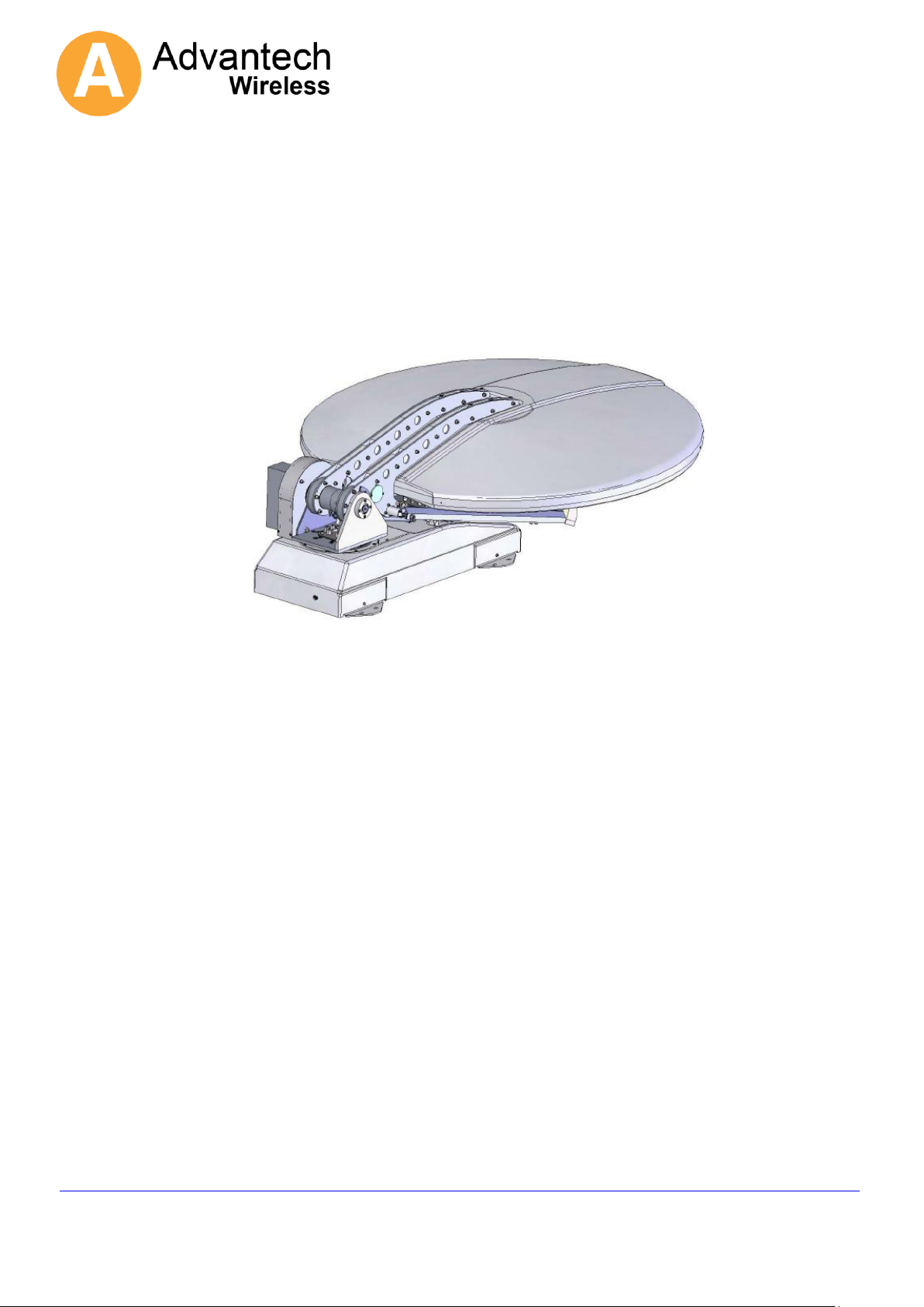
1. Overview – Technical Description
The ENTERPRISE120 is an azimuth over elevation positioning mount with motorised
polarisation control.
All axis feature simple and very robust 24V DC motor drives giving reliable, low backlash,
high and low speed motion controlled by either a jog controller or a fully auto-pointing
controller.
The optical layout is a dual offset Gregorian antenna which naturally produces cross
polarisation patterns which easily meet the 29-25 log theta requirement.
The bearings are sealed for life items that allow for highly accurate motion but require no
maintenance.
A manual over ride is provided for both azimuth and elevation axis to enable stowing the
antenna due to power or other failure.
The RF power amplifier(s) can be fitted either directly onto the feed of securely fitted to
the boom arm.
System weight (without the RF) is 80 kg.
2. Installation and Set-up
The ENTERPRISE120 is fully tested with the controller prior to shipment. All position
feedback, limit switches and motor speeds have been calibrated or set at the factory and
require no adjustment.
Remove the lid and end sections of the shipping crate, adjust forklift forks to roughly 1m
apart or as wide as they will safely go if this cannot be achieved.
Once suitable brackets are available (see attached drawing) these should be fitted to the
antenna roughly in the positions shown on the interface drawing with the slide nuts
provided.
Slings or ropes capable of withstanding the weight of the antenna (80kg) should then be
attached to the brackets, looped over the forks of the forklift and clamped onto the forks to
prevent them slipping off.
Raise the antenna to clear the vehicle roof by a minimum of 0.5m and manoeuvre to the
rear of the vehicle.
Whilst ensuring all cables are clear of mounting points, lower the positioner onto the
vehicle roof and line up all mounting holes.
Ref: PM-ENT120-002-11022
Page 4
ENTERPRISE120
UK Office Phone +44 1480 357 600 Fax +44 1480 357 601
US Office Phone +1 480 839 4136 Fax +1 480 839 0860
Canada Office Phone +1 514 420 0045
Fax +1 514 420 0073
E-mail Sales.UK@AdvantechWireless.com
Website: www.AdvantechWireless.com
Page 4 of 14
The antenna should be secured to the vehicle via the welded brackets to the
ENTERPRISE120 framework on the sides of the antenna base framework. Suitable
vehicle roof bars with clamping nuts (U-Bolts M6) must be used. Additional connections
must be made connecting coax (Tx and Rx), control cable to controller and power cables.
The vehicle roof structure should be stiff enough to prevent no more than a 0.5 dB of TX
gain loss in a 30mph gusting to 45mph wind.
Apply Loctite 242 or similar to all bolts and tighten to a torque of 13 – 15 Nm.
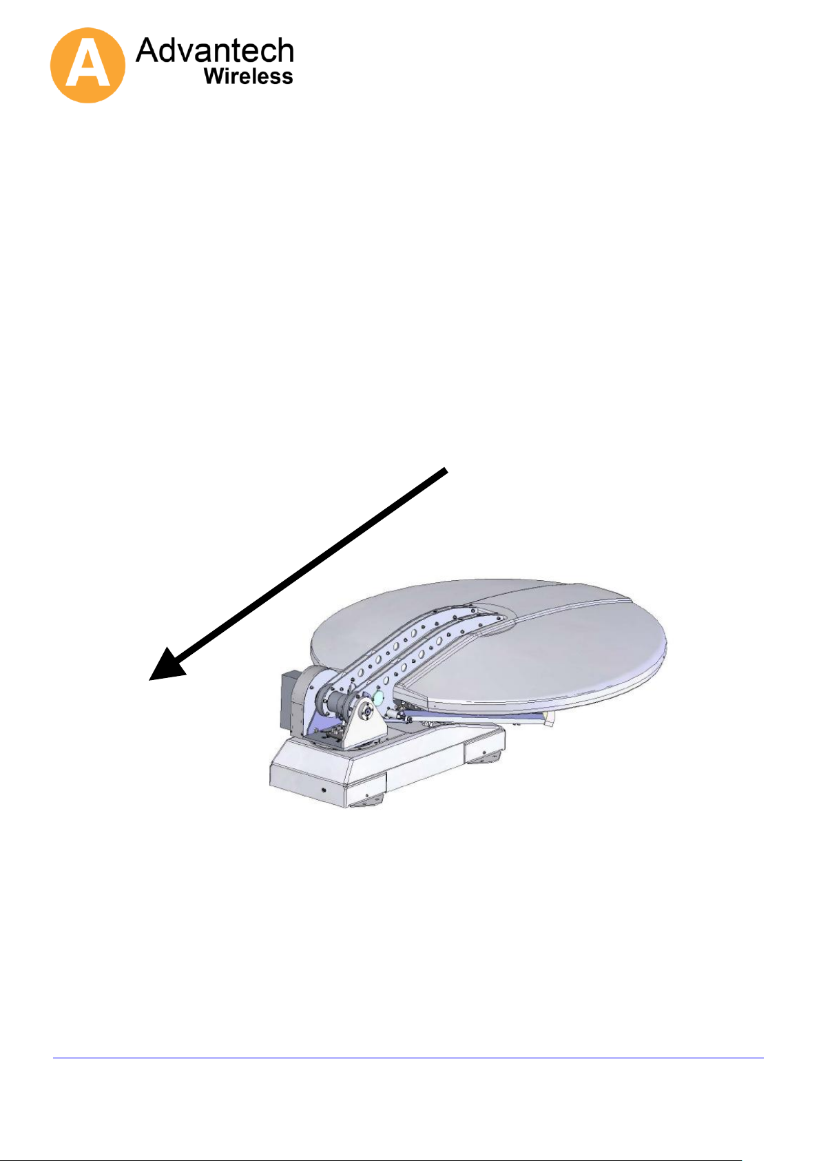
Direction of vehicle travel.
Antenna is to be fitted with the rear facing the direction of travel.
3. i-Point ACU Controller Installation
Ref: PM-ENT120-002-11022
Page 5

ENTERPRISE120
UK Office Phone +44 1480 357 600 Fax +44 1480 357 601
US Office Phone +1 480 839 4136 Fax +1 480 839 0860
Canada Office Phone +1 514 420 0045
Fax +1 514 420 0073
E-mail Sales.UK@AdvantechWireless.com
Website: www.AdvantechWireless.com
Page 5 of 14
Install controller into electronics rack and attach control cable ensuring it is securely and
fully pushed into its connector. (see Addendum 1)
User Interface Unit (UIU)
The antenna controller may be operated directly from the front panel of the User Interface
Unit (UIU), a hand held controller or via a remote control link.
A Graphical User Interface (GUI) program is provided. This runs under Windows 2000 or
Windows XP on any standard PC and communicates with the i-Point ACU via the remote
control port on the front panel of the UIU.
A serial interface cable which connects from the UIU RJ11 connector to a standard 9 way
female serial connector is provided with the UIU. This is wired to plug directly into a
standard 9 way D-type serial port on a PC.
The UIU only implements direct user commands.
It allows the operator to select the reference and target satellites from the existing
list and to command Deploy.
It allows the user to define the Final Pol and Final LNB settings following the
deploy and also allows direct control commands such as Standby, Jog, Stow,
Switch Pol or Switch LNB. A complete list is given below.
The UIU does not allow the user to change parameters or to add or modify data in the
satellite database. These operations can be performed via the GUI.
A typical auto-pointing usage sequence would be:
Ensure that satellite channel data exists for a number of locally visible satellites including
the required reference and, preferably, the target satellites. Data does not need to exist
for the target, but, if it is available, it allows confirmation that the correct satellite has been
acquired.
Ref: PM-ENT120-002-11022
Page 6

ENTERPRISE120
UK Office Phone +44 1480 357 600 Fax +44 1480 357 601
US Office Phone +1 480 839 4136 Fax +1 480 839 0860
Canada Office Phone +1 514 420 0045
Fax +1 514 420 0073
E-mail Sales.UK@AdvantechWireless.com
Website: www.AdvantechWireless.com
Page 6 of 14
Note that if the UIU is to be used for selecting the Reference and Target satellites, then
those satellites must appear in the first 10 slots of satellite data Ensure that the reference
and target satellites are as required and that the final Pol and final LNB settings match the
settings required to access the satellite after acquisition.
Command Deploy (from the UIU or GUI).
For manual or JOG functions
Accessing JOG ANTENNA puts the system into manual jog mode and the Az and El axes
can be jogged using the ^, v,> and < keys. Pressing enter again will toggle the mode
between (Az & El jog) and (Polarisation axis jog (using > and < keys)). If the enter key is
pressed while a ^, v, > or < key is already active then the speed will change to fast.
This is not a latching function and the speed will revert to slow as soon as the enter key is
released. Clear will take the system back out of Jog mode.
4. Maintenance
The antenna should be fully visually inspected at the point of installation and periodically
there after at intervals of not more than 1 year. As the drives require no maintenance or
adjustment this procedure simply involves ensuring there are no worn or damaged
cables, that the waveguide is not damaged or perished and that all fasteners are present
and tightened to the correct torque level.
5. Spares and Replacement Parts
Since no maintenance is required, only electrical parts are recommended as spares.
These parts will not fail from activity, but may fail from environmental exposure.
Ref: PM-ENT120-002-11022
Page 7

ENTERPRISE120
UK Office Phone +44 1480 357 600 Fax +44 1480 357 601
US Office Phone +1 480 839 4136 Fax +1 480 839 0860
Canada Office Phone +1 514 420 0045
Fax +1 514 420 0073
E-mail Sales.UK@AdvantechWireless.com
Website: www.AdvantechWireless.com
Page 7 of 14
6. Manual Over Ride
Azimuth
Insert hexagon key
Elevation
Ensure that the DC power to the unit is switched off, remove the 4 cover screws
indicated, remove the cover then insert hexagon key into the shaft end.
Ref: PM-ENT120-002-11022
Page 8
ENTERPRISE120
UK Office Phone +44 1480 357 600 Fax +44 1480 357 601
US Office Phone +1 480 839 4136 Fax +1 480 839 0860
Canada Office Phone +1 514 420 0045
Fax +1 514 420 0073
E-mail Sales.UK@AdvantechWireless.com
Website: www.AdvantechWireless.com
Page 8 of 14
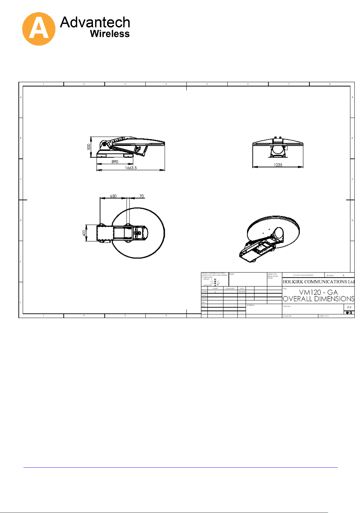
7. Overall Dimensions
Ref: PM-ENT120-002-11022
Page 9

ENTERPRISE120
UK Office Phone +44 1480 357 600 Fax +44 1480 357 601
US Office Phone +1 480 839 4136 Fax +1 480 839 0860
Canada Office Phone +1 514 420 0045
Fax +1 514 420 0073
E-mail Sales.UK@AdvantechWireless.com
Website: www.AdvantechWireless.com
Page 9 of 14
8. Mounting Bracket Positions
Ref: PM-ENT120-002-11022
Page 10

ENTERPRISE120
UK Office Phone +44 1480 357 600 Fax +44 1480 357 601
US Office Phone +1 480 839 4136 Fax +1 480 839 0860
Canada Office Phone +1 514 420 0045
Fax +1 514 420 0073
E-mail Sales.UK@AdvantechWireless.com
Website: www.AdvantechWireless.com
Page 10 of 14
Specification:-
Mechanical Data
Overall dimensions : 1.66m x 1.25m x 0.450m
Geometry : Gregorian offset, dual optic
Reflector material : SMC
Feed interface : WR 75
Azimuth range : +/- 185°
Elevation range : 10~90°
Operating temperature : -30°C ~ +60°C
Weight 95 kg (Depending on options)
Electrical Data
Receive
Polarisation : linear
Frequency band : 10,7 ~12,75 GHz
3dB beam width : 1,3°
Gain @ 12,5 GHz : 41,8 dBi
G/T (30° elevation) @ 12.5 GHz : 21 dBK
Transmit
Polarisation : linear orthogonal
Frequency band : 13,75 ~14,5 GHz
3dB beam width : 1,1°
Gain @ 14,25 GHz : 43 dBi
VSWR : 1,3 : 1 max
Isolation Rx / Tx (13,75~14,5 GHz) : 40 dB min
Isolation Tx / Rx (10,75~12,75GHz) : 75 dB min
Antenna approvals Eutelsat/Intelsat compliant
Power Requirements
Unit requires a regulated 24vdc supply with a 10amp current rating as a minimum
Ref: PM-ENT120-002-11022
Page 11

ENTERPRISE120
UK Office Phone +44 1480 357 600 Fax +44 1480 357 601
US Office Phone +1 480 839 4136 Fax +1 480 839 0860
Canada Office Phone +1 514 420 0045
Fax +1 514 420 0073
E-mail Sales.UK@AdvantechWireless.com
Website: www.AdvantechWireless.com
Page 11 of 14
Addendum 1
i-Point Operation Monitoring
The i-Point Antenna control system is designed to be very simple to operate and is expected to be fully
automatic in acquiring the required satellite signals.
However the system does not provide very much user feedback if the satellite acquisition operation
does not complete.
This document is intended to provide method to gather information on the progress of the satellite
acquisition.
1 Serial Communication
To communicate with the i-Point system a PC with a serial port is required. The information below described the
use of hyper-terminal as a "terminal emulator", but any similar program could be used instead.
One unusual point about the serial interface is that the UIU front panel will keep trying to take control
of the interface. When this happens you may see “garbage characters” generated. To reduce the effects of this
type an extra “carriage return” every 10 seconds or so, The normal serial parameters are 19200,n,8,1 but mobile
systems which connect the UIU to a DVBRCS modem are typically set to 4800,n,8,1.
The Baud rate can be changed via the UIU front panel.
Press the buttons as follows:-
Down arrow *6 Display Shows "User Setup"
Enter Display Shows "Final Pol"
down arrow *4 Display Shows "GPS Output"
Enter Display Shows "4800"
Enter. Display Show "19200".
Clear. Return to main menu.
This baud rate change is not stored. The next time the system is power cycled the baud rate will
revert to normal operation.
The connection is taken from the RJ-11 front panel connector on the i-Point User Interface Unit.
A cable can be supplied but connection details are shown below.
RJ-11 TO 9-PIN D-Type Socket ADAPTER CABLE
To connect a PC to the UIU Front Panel M&C connector use this adapter cable. Adapter
cables must be individually wired. Follow the pin out listed in table below.
The diagram shows the pin out for the RJ-11 connector, looking into the socket on the
panel. This is a 6 pin version of the RJ-11 connector, sometimes known as an RJ-12
D Connector Signal RJ-11 Connector
Pin 1 Common Pin 5
Pin 2 Term Data IN Pin 3
Pin 3 Term Data OUT Pin 2
Pin 5 Ground Pin 1
Pin 6 Not Used Pin 4
Do Not Connect + 5VDC @ 100 mA Pin 6
Same table in RJ-11 order
Ref: PM-ENT120-002-11022
Page 12

ENTERPRISE120
UK Office Phone +44 1480 357 600 Fax +44 1480 357 601
US Office Phone +1 480 839 4136 Fax +1 480 839 0860
Canada Office Phone +1 514 420 0045
Fax +1 514 420 0073
E-mail Sales.UK@AdvantechWireless.com
Website: www.AdvantechWireless.com
Page 12 of 14
D Connector Signal RJ-11 Connector
Pin 5 Ground Pin 1
Pin 3 Term Data OUT Pin 2
Pin 2 Term Data IN Pin 3
Pin 6 Not Used Pin 4
Pin 1 Common Pin 5
Do Not Connect + 5VDC @ 100 mA Pin 6
This diagram shows the pin order when viewed from
plug cable entry.
2 Normal Operation
The i-Point's normal "deploy" operation is made up of several stages.
There is information provided at some stages which can be helpful to diagnose a system having
problems.
First start to capture the information on the serial port. (In hyper-terminal use the "Transfer\Capture
text" menu and provide a filename.) If you need assistance interpreting the information then it can be
e-mailed to support.europe@AdvantechWireless.com .
Then type the command "debugport 0". This will instruct the system to provide additional diagnostic
data.
Then type the command "deploy".
2.1 Unstow
No useful information about this step. The antenna is driven from the current position to the "unstow"
position.
2.2 Orientation
During this step 3 pieces of information are gathered.
1. The GPS is read to get the current location on earth.
2. The magnetometer is read to get a heading angle for the platform. This is the geographical
direction that the antenna is pointing at the unstow position.
3. Then the antenna is driven to an elevation angle above the geostationary arc to take a "noise floor"
measurement.
Once this drive has been completed the GPS and the magnetometer readings can be checked.
To see the gps data type the command "gps". Check that the last line indicates that the signal is valid.
Ref: PM-ENT120-002-11022
Page 13

ENTERPRISE120
UK Office Phone +44 1480 357 600 Fax +44 1480 357 601
US Office Phone +1 480 839 4136 Fax +1 480 839 0860
Canada Office Phone +1 514 420 0045
Fax +1 514 420 0073
E-mail Sales.UK@AdvantechWireless.com
Website: www.AdvantechWireless.com
Page 13 of 14
To check the magnetometer heading information type "platform". The third number is the heading
angle in degrees.
This number could be as much as +/- 20 degrees from the correct reading without stopping the
system working. If the error is greater than 20 degrees then this can cause problems.
If required the correct heading can be provided.
Type the command "platform 0 0 zz" where zz is the correct heading in degrees.
2.3 Satellite Sweep
The start of the satellite sweep is shown in the diagnostic data.
During this stage the antenna elevation and Pol angles are set to the correct angles for the reference
satellite and a range of azimuth movement is swept looking for an RF signal.
If during this phase a message is seen reporting a “horizon scan” has been started then this indicates
that no RF signal above the noise floor was detected during the sweep. This is an indication that there
is a problem with the LNB of L-band cabling from the LNB to the i-Point ACU.
2.4 Peak on reference satellite
No diagnostic data is provided for this stage but the "cross scan" movements of the antenna can be
seen.
2.5 Identify reference satellite
At the beginning of this step the diagnostic data reports "Looking at ww" where ww is the longitude of
the reference satellite.
At the end of this stage there is a line of information which starts "CTRL" first number indicates the
satellite longitude being checked. The last number is the number of DVB channels checked.
The second to last number is the number of channels successfully decoded. The success number
should be more than half of the number of channels checked.
If less than half of the channels checked failed to be identified then the system will start to check
channels from other satellites. Once it completes the list of satellites the system will report “walking
the arc”. This is an indication that it found an RF signal but was unable to identify it as any known
satellite. In some cases the system will find a satellite which is not the reference satellite, but is one
which it recognises when the channels are checked. If a satellite is recognised the system calculates
a more accurate reading for the platform heading. It indicates the correction of the heading, before
moving on to the next stage.
2.6 Goto target satellite
No useful data is provided here.
2.7 Peak on target satellite
No diagnostic data is provided for this stage but again the "cross scan" movements of the antenna
can be seen.
2.8 Identify target satellites
Repeat of the previous "identify reference satellite" step, this time for the target.
At the beginning of this step the diagnostic data reports "Looking at ww" where ww is the longitude of
the target satellite.
At the end of this stage there is a line of information which starts "CTRL" first number indicates the
satellite longitude being checked. The last number is the number of DVB channels checked.
The second to last number is the number of channels successfully decoded. The success number
Ref: PM-ENT120-002-11022
Page 14

ENTERPRISE120
UK Office Phone +44 1480 357 600 Fax +44 1480 357 601
US Office Phone +1 480 839 4136 Fax +1 480 839 0860
Canada Office Phone +1 514 420 0045
Fax +1 514 420 0073
E-mail Sales.UK@AdvantechWireless.com
Website: www.AdvantechWireless.com
Page 14 of 14
should be more than half of the number of channels checked. Again if the system peaks up on the
wrong satellite, but it is recognised as such then the system will attempt to got to the target satellite
again. If the satellite is recognised then the system will re-calculate the platform heading.
2.9 Set polarisation to final position.
At this stage the Feed is moved to the final Pol position.
3 GUI Program
The ipoint.exe program can be used to upload and download whole sets of configuration data and
satellite data. The program only works when the i-Point serial port is set to 19200. (See Serial Communication)
above.
Ref: PM-ENT120-002-11022
 Loading...