

Advanced Protection XGA User Manual [en, es]
ENGLISH
TE
XTE
XGA &
XGA
Series
Surge Protective Device (SPD)
Installation, Operation
& Maintenance Manual
WARNING – IMPORTANT – PLEASE READ – WARNING
Safety First – Hazardous Voltage & Shock Hazard
• Only qualied licensed electricians should install or service SPDs
• Hazardous voltages exist within SPDs
• SPDs should never be installed or serviced when energized
• Use appropriate safety precautions including Personal Protection Equipment
• Failure to follow these instructions can result in death, serious injury, and/or equipment damage
• This manual shall be read in its entirety prior to installing
V
Bonding and Grounding Hazard
Verify that the neutral conductor in the service entrance
equipment is bonded to ground in accordance with the
National Electric Code (NEC®) and all applicable codes.
Verify that the neutral terminal (XO) on the secondary side of
distribution transformers are grounded to the system ground in
accordance with the NEC® and all applicable codes.
During installation into an electrical system the SPD must
not be energized until the electrical system is completely
installed, inspected and tested. All conductors must be
connected and functional including the neutral (if required).
The voltage rating of the SPD and system must be veried
before energizing the SPD.
Failure to follow these guidelines can lead to abnormally high
voltages at the SPD. This may cause the SPD to fail. The
warranty is voided if the SPD is incorrectly installed and/or if
the neutral conductor in the service entrance equipment or
downstream of separately derived systems is not bonded to
ground in accordance with the NEC®.
Do Not Hi-Pot Test SPDs
Any factory or on-site testing of power distribution
equipment that exceeds normal operating voltage such as
high-potential insulation testing, or any other tests where the
suppression components will be subjected to higher voltage
than their rated Maximum Continuous Operating Voltage
(MCOV) must be conducted with the SPD disconnected
from the power source. For 4-wire systems, the neutral
connection at the SPD must also be disconnected prior to
performing high-potential testing and then reconnected after
test completion.
Failure to disconnect SPD and associated components
during elevated voltage testing will damage the SPD and
will void the warranty.
Advanced Protection Technologies
14550 58th Street North
(800) 237-4567·(727) 535-6339 · Fax (727) 539-8955
UL is a registered trademark of Underwriters Laboratories, NEC® and National Electrical Code are
registered trademarks of National Fire Protection Association, C62.41.1-2002, C62.41.2-2002,
C62.45-2002, C62.72-2007 are registered trademarks of IEEE.
www.aptsurge.com · info@apttvss.com
Clearwater, Florida 33760
·
European Authorized Representative
Obelis s.a.
Boulevard Général Wahis 53
1030 Brussels, BELGIUM
Tel: +(32) 2. 732.59.54
Fax: +(32) 2. 732.60.03
E-Mail: mail@obelis.net
10.22.12.lh #8381
INTRODUCTION
Thank you for choosing an APT Surge Protective Device
(SPD). This is a high quality, high energy surge suppressor
designed to protect sensitive equipment from damaging
transient overvoltages.
Proper installation is important to maximize performance.
Please follow steps outlined herein.
This entire Operation & Maintenance Manual should be
read prior to beginning installation. These instructions are
not intended to replace national or local codes. Follow
all applicable electrical codes to ensure compliance.
Installation of this SPD should only be performed by
qualied electrical personnel.
APT SPDs are extensively tested in accordance with industry
standards such as ANSI/IEEE C62.41.1, C62.41.2, C62.45,
C62.62, C62.72, UL 1449, UL 1283, IEC 61643, etc.
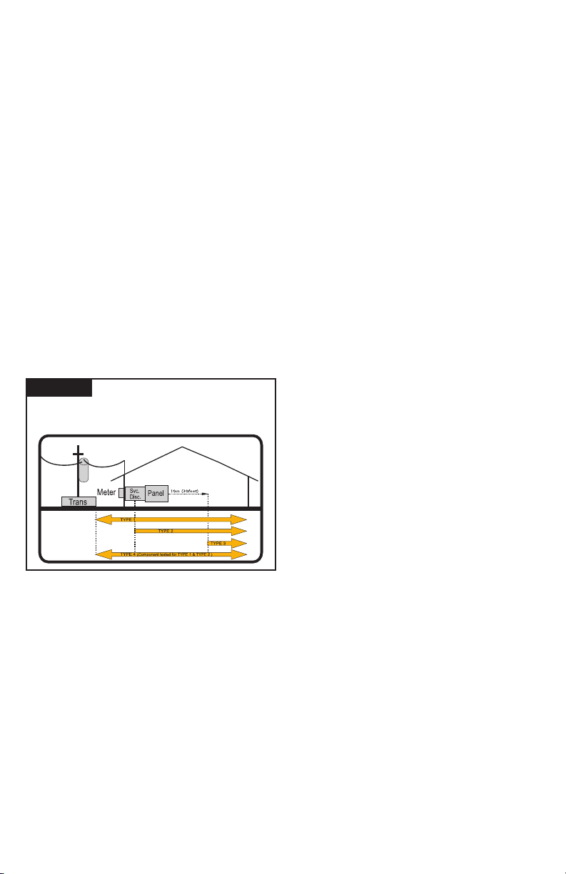
This SPD is a single-port parallel-connected device
intended for service entrance, panelboard or downstream
installation for IEEE Category C, B or A applications.
Major Industry Nomenclature Changes
Effective 2008-2009
Be aware that UL 1449 Third Edition and 2008 NEC® Article
285 generated substantial changes.
Figure 1
(also coincides with ANSI/IEEE C62.41.2 - 2002 Categories C, B & A)
NEC® Article 285 & UL 1449-3
SPD Types: Types 1, 2, 3, & 4
Based on Location within electrical distribution system
▪ The term TVSS changed to SPD
▪ Types 1, 2, 3 & 4 SPDs are created
▪ UL 1449 clamping voltage performance testing
changed from 500A to 3,000A
▪ UL 1449 added new I nominal testing (I
consists of more rigorous duty-cycle testing
This SPD complies with the latest regulatory actions and
is UL Listed as such.
For further information, please review latest editions of
NEC® Art. 285, UL 1449 or contact APT Tech Support at
(800) 237-4567.
GENERAL INFORMATION
This is a Type 2 SPD. It includes internal overcurrent protection.
Type 2 SPDs are suitable for installation on the load side of the
service disconnect overcurrent device.
), which
n
This device features internal overcurrent and overtemperature
protection that will disconnect effected surge suppression
components at the end of their useful life, but will maintain
power to the load – now unprotected. If this situation is
undesirable for the application, follow these instructions for
servicing or replacing the device.
Service of this unit consists of replacing internal modules and/
or display assembly.
There are no user-serviceable parts inside the replaceable
modules. Do not attempt to disassemble the module as it stores
charge and is potted.
Simplied Explanation of Operation
SPDs sense overvoltage and create a momentary short
circuit to redirect harmful surge energy to earth ground.
Then they reset automatically and wait for the next surge.
This is similar to the pressure relief valve on a water
heater: pressure goes up, valve opens to relieve pressure
and then resets. In an electrical system, an SPD senses
overvoltage, shorts temporarily sending energy to ground
and then resets. SPDs are capable of repeating this
function thousands of times.
Parallel Connection
This is a Parallel connected SPD – not series connected.
As outlined above, an SPD ‘drains off’ excessive voltage
from an electrical system. Because of parallel connection,
installation of the SPD near the equipment to be protected
is satisfactory. This effect is similar to ushing any toilet in a
house; pressure in the shower goes down. In an electrical
system, a parallel connected SPD will remove excessive
voltage off the entire system (assuming reasonable
proximity).
Tip: It is critically important that wiring leads be congured as
short & straight as possible. Avoid long leads. Avoid sharp
bends. Route SPD conductors in the same conduit. Leads do
not have to be sized for the entire load – this SPD is parallel
connected, not series connected. As a generalization, 6 AWG
works ne.
Precautionary Statement Regarding SPDs on
Ungrounded Systems
Caution – Ungrounded systems are inherently unstable and
can produce excessively high line-to-ground voltages during
certain fault conditions. During these fault conditions, any
electrical equipment including an SPD, may be subjected
to voltages which exceed their designed ratings. This
information is being provided to the user so that an informed
decision can be made before installing any electrical
equipment on an ungrounded power system.
Unpacking & Preliminary Inspection
Inspect the entire shipping container for damage or signs
of mishandling. Remove the packing materials and further
inspect the unit for any obvious shipping damages.
If any damage was found and is a result of shipping or
handling, immediately le a claim with the shipping company
and forward a copy to APT.
Storage Environment
This SPD should be stored in a clean, dry environment.
Storage temperature range is -40°C (-40°F) to +60°C
(+140°F). Avoid exposure to high condensation.
2

PRE-INSTALLATION & INSTALLATION PLANNING
Operating Environment
The standard unit is in a Type 1 enclosure. Other enclosure
types are available as options. Before installing, ensure
that your enclosure type and application are appropriate
per NEMA 250 with regard to moisture, dirt, excessive dust,
ammable materials or atmospheres, corrosive vapors, etc.
This SPD is designed in an ambient temperature range of -40°C
(-40°F) to +60°C (+140°F) with a relative humidity of 0% to 95%
(non-condensing). Excessive temperature may inadvertently
operate internal thermal overtemperature protectors.
Audible Noise
SPD background noise is negligible or non-existent, and
does not restrict the location of installation.
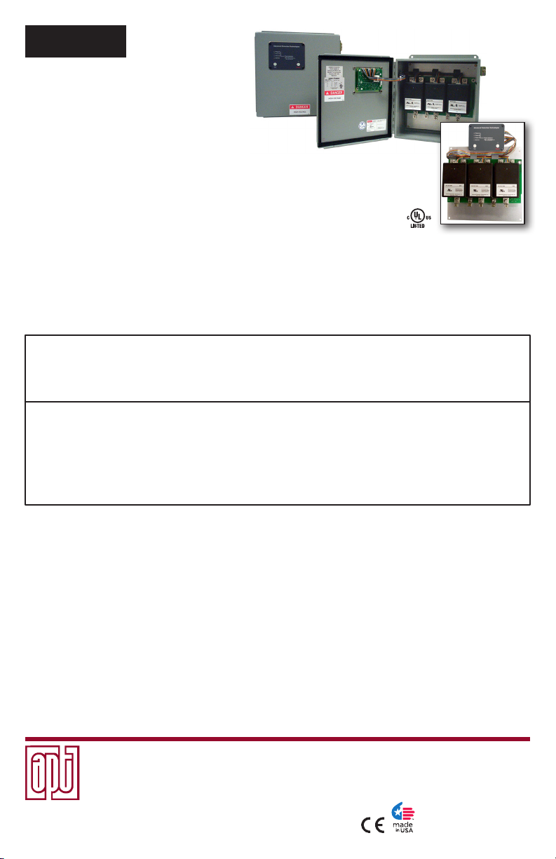
Mounting, Dimensions, and Weight
This SPD is designed to be wall mounted. The standard
enclosure is: 12” x 12” x 6” (L/W/D), and the weight is
25 lbs. The XTE Series is designed for internal mounting
in the electrical distribution equipment. Standard backplane
size is: 10.75” x 10.88” x 4.5”, and the weight is 15 lbs.
Service Clearance
Service clearance is needed at the front of the TE Series
unit only, 36 inches minimum is the required distance for
clearance pursuant to the NEC®.
Maximizing SPD Performance
SPD’s must be located as close to the circuit as possible
to minimize parasitic losses. Surges are high current, high
frequency events that cause substantial voltage drops across
conductors. This hurts SPD performance. Use the shortest &
straightest possible leads. Pre-Plan installations and ensure
that nearest breaker positions are used. If new construction,
adjust breaker locations as appropriate.
Tip: Voltage drops for normal 120V or 277V lines might be 2-3V per
hundred feet. In surge applications, voltage drops might be 100-150V
per foot. These voltage drops add to clamping voltage, thus hurting
performance. Make every effort to keep leads short and straight.
As distribution gear becomes larger, shorter leads are more
difcult to accomplish. When longer leads are unavoidable,
gently twist leads together (one to two twists per foot), or tiewrap leads together.
Tip: surges create magnetic elds per the ‘right-hand rule’. When current
goes in direction of thumb, magnetic eld is in direction of curl of ngers.
As surge current goes to SPD, elds are created in one direction. When
the SPD sends those currents to neutral and/or ground, current goes
in the opposite direction. If ‘coming & going’ are on the same axis, the
magnetic elds can be cancelled, thus avoiding performance decrease.
Gentle twists, bundling & tie-wraps accomplish this.
Cascade Surge Protection
For optimum surge protection, cascade or staged surge
suppression should be implemented at the service entrance
and downstream locations as appropriate. Known or expected
surge sources, as well as sensitive loads, should also have
localized surge suppression. For interconnected electronic
loads (data cabling), SPDs should also be utilized to protect
the devices on either end of the interconnecting data cables.
Overcurrent Protection
SPDs draw very little current under normal conditions and
conduct for a brief duration upon encountering a transient
surge current. This SPD contain internal overcurrent and
overtemperature protection to protect against abnormal
voltage conditions.
Supplemental overcurrent protection is not required to protect
this SPD. However, connecting conductors require protection
in Type 2 or 4 applications. Follow applicable codes.
Circuit Breaker and Disconnect Switch
This XGA family SPD is tested and qualied as a Type 2 SPD
per UL 1449 Third Edition and 2008 NEC®. This SPD can be
installed on the load side of the service overcurrent device per
2008 NEC® Article 285.
When connected on load side of main disconnect, we suggest
connecting via a 60A circuit breaker. The circuit breaker is the
intended disconnect switch and provides short circuit protection
to the connecting conductors. The XGA Series has internal
overload protection elements within the product. A breaker or
disconnect is not required for the SPD’s overcurrent protection.
XGA SPD’s have demonstrated 200kA Short Circuit Current
Ratings (SCCR). Confer to label on unit.
Wire Size and Installation Torque
This is a parallel-connected SPD; it is not series-connected.
The size of the SPD wiring is independent of the ampere
rating of the protected circuit. Recommended wire is 6
AWG for phase, neutral and ground connections. Torque
connections to 18 inch-pounds. Conductor length should
be as short as possible.
If other wire sizes are used, we recommend that all
conductors be the same gauge. Note that larger conductor
might appear to be benecial; however, it tends to have
the same inductance as smaller conductor and is more
difcult to work with.
Terminals accept 14 - 2 AWG conductor with 6 AWG being
preferred. Coordinate conductor size and overcurrent
Special Enclosure Considerations
Removing and Reconnecting the Ribbon Cables
The ribbon cables are marked with matching phase
connections. If any of the cables are removed, reconnect
the cables as marked.
NEMA Type 4X Enclosure
On rare occasions in high temperature climates, XGA’s
inside clear-cover polycarbonate enclosures have
experienced internal temperatures exceeding 200°F.
This inadvertently operates the overtemperature safety
disconnectors inside the SPD. We recommend positioning
the unit so that the clear front avoids direct summer sunlight
by shading or not facing west.
The NEMA Type 4X enclosure is shipped with its mounting
brackets and installation screws packaged inside it. Use
the enclosed 1/4-20 x 1/2 in. slotted screws to secure the
brackets to the enclosure before installing the XGA SPD
device. Torque these screws to a maximum of 50lb-in.
(6N·m). When installing the cover for the NEMA Type
4X enclosure, torque the cover screws to a maximum of
25lbs-in. (3 N·m).
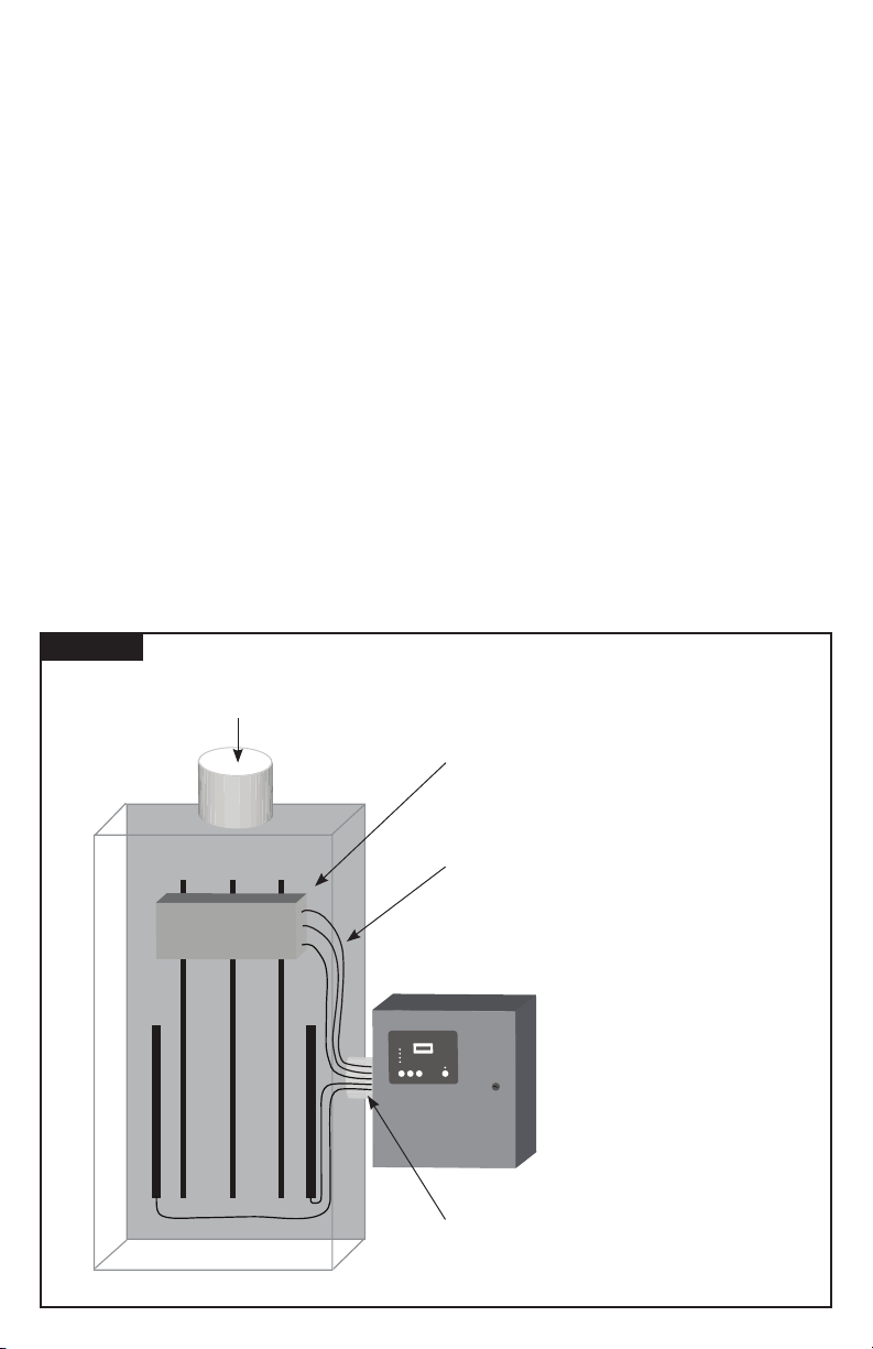
Flush Mount Option
Remove the display panel and barrier before making any
electrical connections. Replace the barrier and display panel
before energizing the device.
3
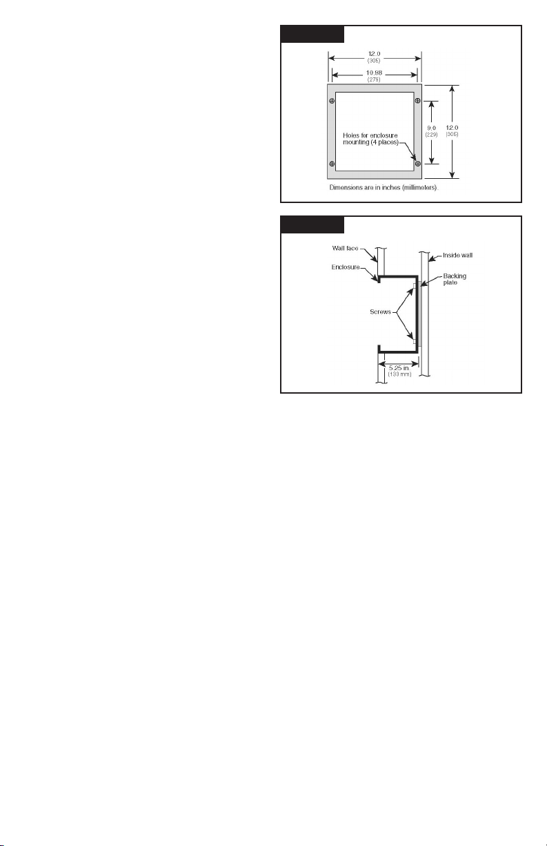
The XGA is approximately 5.25 in. (133 mm) deep. The XGA
will not ush mount unless there is at least 5.25 in. (133 mm)
of clearance. The XGA is not designed to ush mount on a
typical 2 x 4 stud wall.
Follow steps 1-5 to ush mount the XGA.
1. Before removing the trim, disconnect the ribbon cables
and ground wire from the modules.
2. Mount the device as close as possible to the panel being
protected. Create a wall opening slightly larger than 12
in. high by 12 in. wide (305 mm high by 305 mm wide).
See gure 2.
3. Install a backing plate inside the wall cavity 5.25 in.
(133 mm) from the wall face such that the XGA will be
supported from its back. See gure 3. Note the mounting
holes on the back of the enclosure. Also note that the
XGA weighs 25 lb (12 kg) maximum.
4. Configure the electrical conductor and conduit
connections consistent with the wiring instructions
beginning on page 7.
5. Carefully reattach the ribbon cables and the ground wire
to the modules and reattach the display panel/cover
before energizing and testing the device.
Terminals
Terminals will accept 14 - 2 AWG conductor and are provided
for line (phase), neutral (if used), and equipment safety
ground connections. 8 AWG is the minimum recommended
wire size because UL testing and evaluation was performed
using 8 AWG.
ators to ensure proper operation. We also
recommend keeping the SPD clean as appropriate.
Figure 2
Figure 3
FLUSH MOUNT FRONT VIEW
FLUSH MOUNT SIDE VIEW
Shortest Leads Possible
• Leads must be as short and straight as possible-
See NEC® Art. 285.12
• Pretend wire is $1000 per foot coming out of your pocket
• No long leads
• No sharp bends
• No wire nuts
• How short is short enough? As short as you can make it
• How long is too long? If anyone else can make it shorter
Conguration Management & Part Numbering System
TE series correct installation orientation is such that the door
will hinge from the left. (XTE has no enclosure or door and is
typically factory installed)
Locate the unit’s printed identication nameplate on the inside
of the hinged door, although options may dictate placing it in
a conspicuous location elsewhere. The model number can
be decoded as follows:
• TE identies an external mount Transient Eliminator
®
followed by a slash (/). XTE identies an enclosure - less
model followed by a slash (/).
• A one or two digit number will precede the letters XGA.
This number indicates the voltage and wiring conguration
of the device. Refer to page 5 to identify and conrm
correct application.
• XGA identies the XGA Series, followed by a slash (/)
• Following the second slash may be a /240. These numbers
identify optional per phase Surge Current Ratings. (Please note:
The Standard 160kA Rating does not have a /160 identier.)
Options are identied after the Surge Current Rating and
are individually separated by a slash. (Options are detailed
later in this manual.)
4
Example: TE/2XGA/240/DC/RM/4X identies a Transient
Eliminator® XGA Series SPD (external mount), 208Y/120V, 3
Phase, 4 Wire (plus Ground), with a 240kA per phase Surge
Current Rating with: Dry Contact, Remote Monitor and a
NEMA 4X Enclosure.
Voltage Rating
Before installing SPD, verify that it has the same voltage
rating as the power distribution system. Compare the SPD’s
nameplate voltage or model number and ensure that SPD
conguration matches the intended power source. See Table 1.
The specier or the user of the device should be familiar with the
conguration and arrangement of the power distribution system
in which any SPD is to be installed. The system conguration
of any power distribution system is based strictly on how the
secondary windings of the transformer supplying the service
entrance main or load are congured. This includes whether
or not the transformer windings are referenced to earth via a
grounding conductor. The system conguration is not based on
how any specic load or equipment is connected to a particular
power distribution system.
480V System Example: SPDs should be installed per the
electrical system, not per a load or motor’s wiring connection.
For example, a 480V three phase motor might appear to be
connected as a 480V Delta. In actuality, the serving distribution
system might be a 480Y/277V grounded Wye, with or without
a neutral pulled to the motor or MCC. The system is still a
480Y/277V Wye, even though the load is connected as a
Delta. A grounded Wye has a dened reference to ground
(i.e., neutral is bonded to ground). Some Delta systems are
ungrounded, which have no reference to ground and are known
to become unstable in certain situations. Such instability can
cause line to ground voltage uctuations that may prematurely
Do not create model numbers from this chart as all features are not available on all models
}
Table 1: MODEL NUMBER DECODER
ll /
TE = Transient Eliminator, Listed Type 2
SPD in NEMA 1 enclosure
XTE = Transient Eliminator, Recognized
Type 4 SPD on backplane for installation
within gear in Type 2 installation (display
on 6’ cable)
Voltage Code for Electrical System
Common North American Systems:
1 = 240/120V Split Phase - 1Ø 3W+Grnd (Fig 1)
2 = 208Y/120V Wye - 3Ø 4W+Grnd (Fig 2)
3 = 240/120V High Leg Delta (B High) (Fig 3)
4 = 480Y/277V Wye - 3Ø 4W+Grnd (Fig 2)
5 = 480V Delta - 3Ø 3W+Grnd (Fig 4) & HRG Wye
8 = 600Y/347V Wye - 3Ø 4W+Grnd (Fig 2)
Other Available Systems - Conrmation encouraged:
15 = 254/127V Split Phase - 1Ø 3W+Grnd (Fig 1)
18 = 480/240V Split Phase, or Two legs of Wye (Call)
21 = 220Y/127V Wye - 3Ø 4W+Grnd (Fig 2)
41 = 520Y/300V Wye - 3Ø 4W+Grnd (Fig 2)
42 = 415Y/240V Wye - 3Ø 4W+Grnd (Fig 2)
43 = 400Y/230V Wye - 3Ø 4W+Grnd (Fig 2)
44 = 440Y/250V Wye - 3Ø 4W+Grnd (Fig 2)
51 = 480V B Corner Grnd Delta, 3Ø 3W+Grnd (Fig 6)
06 = 240V Delta - 3Ø 3W+Grnd (Fig 4)
61 = 240V B Corner Grnd Delta, 3Ø 3W+Grnd (Fig 6)
07 = 380Y/220V Wye - 3Ø 4W+Grnd (Fig 2)
09 = 600V Delta - 3Ø 3W+Grnd (Fig 4) & HRG Wye
91 = 600V B Corner Grnd Delta, 3Ø 3W+Grnd (Fig 6)
ll
/ XGA /
Model Family
XGA = XGA Family
160kA rating standard
lll/lll...
Option Sufxes (Seperated by slashes / )
/240
=
240kA Option
/090
=
090kA SAD option (120/240V & 208Y/120)
/130
=
130kA SAD option (120/240V & 208Y/120)
/170
=
170kA SAD option (120/240V & 208Y/120)
/DC
=
Dry Contacts
Two sets Form C (24V, 1A)
/SC
=
Surge Counter, six digit LCD
/2S
=
Dual Surge Counter
/12
=
NEMA 12 Enclosure (12” x 12” x 6”)
/3R
=
NEMA 3R Enclosure
(12” x 12” x 6” - display inside door)
/04
=
NEMA 4 Enclosure
(12” x 12” x 6” - display inside door)
/FM
=
Flush Mount enclosure, NEMA 1 only
(wall cavity size: 12”x12”x6” deep)
/4X
=
NEMA 4X Non-metallic enclosure
(polycabonate, 14”x12”x6” - display inside door)
/4S
=
NEMA 4S Stainless Steel enclosure
(12”x12”x6” - display inside door)
/TN
=
NEMA 1/12/3R/4 Enclosure
(10” x 10” x 6”)
(Note: Enclosure-less version for OEM uses XTE prex)
Available Accessory (order seperately)
RM
=
Remote Monitor
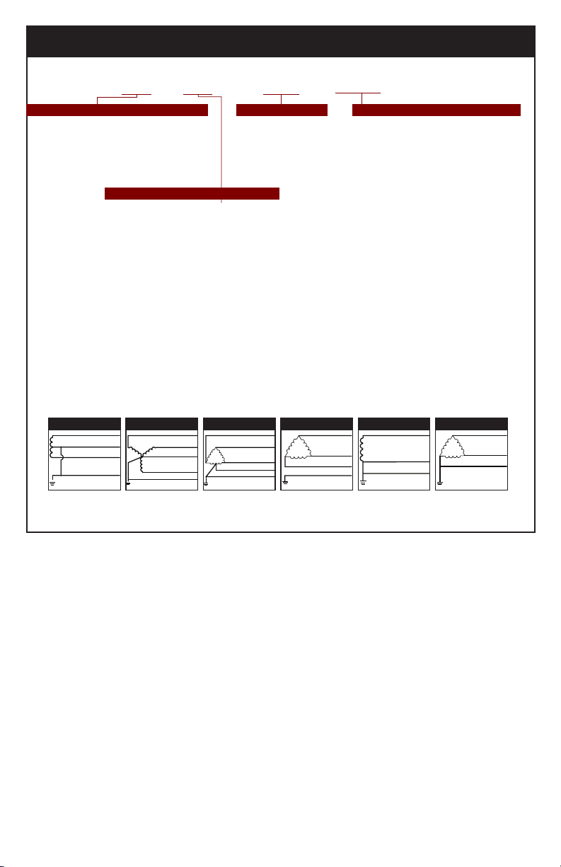
Figure 1 Figure 2 Figure 3 Figure 4 Figure 5 Figure 6
Hot (BLK)
V
}
Neutral (WHT)
}
V
Hot (BLK)
Ground (GRN)
SPLIT
2 Hots, 1 Neu, 1 Grnd
Phase A (BLK)
Phase B (BLK)
B
A
Neutral (WHT)
N
V
}
Phase C (BLK)
C
Ground (GRN)
WYE
3 Hots, 1 Neu, 1 Grnd
Phase A (BLK)
Phase B (ORNG)
V
}
Phase C (BLK)
Neutral (WHT)
Ground (GRN)
HI-LEG DELTA (B High)
3 Hots, (B HIGH),
1 Neu, 1 Grnd
Phase A (BLK)
V
}
Phase B (BLK)
Phase C (BLK)
Ground (GRN)
DELTA & HRG WYE
3 Hots, 1 Grnd
Hot (BLK)
V
Neutral (WHT)
Ground (GRN)
SINGLE POLE
1 Hot, 1 Neu, 1 Grnd
Phase A (BLK)
V
}
Phase C (BLK)
Ground (GRN)
CORNER GROUND
DELTA (B grounded)
2 Hots, 1 Grnd
fail SPDs. For this reason, the NEC® Article 285 has placed
SPD restrictions on ungrounded systems. As generalizations,
SPDs for ungrounded systems can be installed on grounded
systems with a clamping performance penalty. However, SPDs
for grounded systems installed on ungrounded systems are
almost certainly destined for premature failure. Call APT Tech
Support at (800) 237-4567 for further information.
System Grounding
An equipment grounding conductor must be used on all
electrical circuits connected to the SPD.
For the best performance, use a single point ground system
where the service entrance grounding electrode system is
connected to and bonded to all other available electrodes,
building steel, metal water pipes, driven rods, etc. (for reference
see: IEEE Std 142-2007).
For sensitive electronics and computer systems, we
recommend that the ground impedance measurement be
as low as possible. When metallic raceway is used as an
additional grounding conductor, an insulated grounding
conductor should be run inside the raceway and sized per the
NEC®. Adequate electrical continuity must be maintained at all
raceway connections. Do not use isolating bushings to interrupt
a metallic raceway run.
A separate isolated ground for the SPD is NOT recommended.
Proper equipment connections to grounding system and
ground grid continuity should be veried via inspections and
testing on a regular basis as part of a comprehensive electrical
maintenance program.
On 4-Wire Power Systems, neutral to ground bonding (Main
Bonding Jumper) must be installed per the NEC®. Failure to
do so WILL damage SPDs.
UL 1283 required language concerning the installation
of EMI Filters
a) An insulated grounding conductor that is identical in
size and insulation material and thickness to the grounded
and ungrounded circuit supply conductors, except that
it is green with or without one or more yellow stripes,
is to be installed as part of the circuit that supplies the
lter. Reference should be made to Table 250-122 of the
National Electrical Code regarding the appropriate size of
the grounding conductor.
5
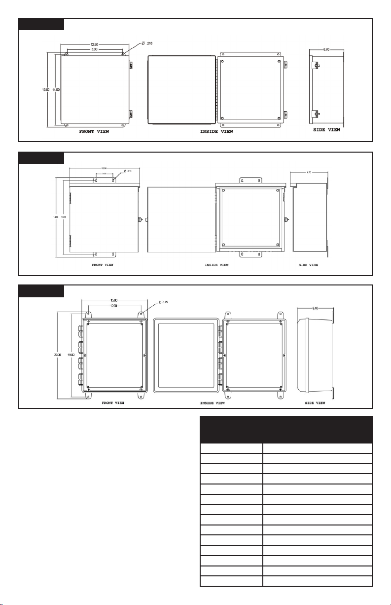
Figure 4
SPD DIMENSIONS: NEMA TYPE 1, 4, AND 4X STAINLESS STEEL
Figure 5
Figure 6
SPD DIMENSIONS: NEMA TYPE 3R
SPD DIMENSIONS: NEMA TYPE 4X PLASTIC
b) The grounding conductor mentioned in item “a” is to
be grounded to earth at the service equipment or other
acceptable building earth ground such as the building
frame in the case of a high-rise steel-frame structure.
c) Any attachment-plug receptacles in the vicinity of the
lter are to be of a grounding type, and the grounding
conductors serving these receptacles are to be connected
to earth ground at the service equipment or other
acceptable building earth ground such as the building
frame in the case of a high-rise steel-frame structure.
d) Pressure terminal or pressure splicing connectors
and soldering lugs used in the installation of the lter
shall be identied as being suitable for the material of
the conductors. Conductors of dissimilar metals shall not
be intermixed in a terminal or splicing connector where
physical contact occurs between dissimilar conductors
unless the device is identified for the purpose and
conditions of use.
6
Table 2: VOLTAGE RATING AND
SERVICE TYPE
TE & XTE / 1XGA
TE & XTE / 11XGA
TE & XTE / 12XGA
TE & XTE / 2XGA
TE & XTE / 3XGA
TE & XTE / 4XGA
TE & XTE / 5XGA
TE & XTE / 51XGA
TE & XTE / 6XGA
TE & XTE / 61XGA
TE & XTE / 7XGA
TE & XTE / 8XGA
TE & XTE / 9XGA
TE & XTE / 91XGA
120/240 Single Phase, 3 Wire, "Grounded"
120 Single Phase, 2 Wire, "Grounded"
240 Single Phase, 2 Wire, "Grounded"
120/208 Three Phase, 4 Wire, "Grounded", WYE
120/240 Three Phase, 4 Wire, "High-Leg", DELTA
277/480 Three Phase, 4 Wire, "Grounded", WYE
480 Three Phase, 3 Wire, DELTA
480 Three Phase, "Corner Grounded", DELTA
240 Three Phase, 3 Wire, DELTA
240 Three Phase, "Corner Grounded", DELTA
220/380 Three Phase, 4 Wire, "Grounded", WYE
347/600 Three Phase, 4 Wire, "Grounded", WYE
600 Three Phase, 3 Wire, DELTA
600 Three Phase, "Corner Grounded" DELTA
INSTALLATION
Common Problems to Avoid
▪ Conrm System voltage to SPD voltage (120V SPD will fail instantly on 240V, 277V, etc.).
▪ Locate SPD close so leads are short & straight as possible (or will seriously hurt performance).
▪ Make sure N-G or XO bonding meets NEC
▪ Energize SPD AFTER system is stabilized & checked (inadvertent system problem may fail SPD).
▪ SPDs are regulated by NEC
®
Article 285 and UL 1449.
▪ Never Hi-Pot test any SPD (will prematurely fail SPD).
Pre-Plan your installation.
You will need to accomplish the following:
▪ Meet all National and Local codes (NEC
▪ Mount SPD as close to panel or equipment as possible to keep leads short.
▪ Ensure leads are as short and straight as possible, including neutral and ground. Consider a breaker position that
is closest to the SPD and the panel’s neutral & ground.
▪ Suggested breaker & conductor size is 60A-30A with 6 AWG (60A preferred).
▪ Make sure system is grounded per NEC
1. Use a voltmeter to check all voltages to ensure correct SPD.
2. If SPD has Dry Contact, Remote Monitoring or Remote Display, pre-plan their installation
3. Remove power for panel. Conrm panel is deenergized.
4. Identify breaker location and SPD location.
5. Make sure leads are short! Reducing inches matters! Pretend that connector leads cost you $1000 per foot!
6. Remove an appropriately sized knockout from panel. Create an appropriately sized hole in the SPD enclosure.
7. Mount SPD.
8. Connect conductors as appropriate – short and straight as possible (Note that Hi-Legs are Phase B).
9. Label or mark conductors as appropriate (neutral: white, ground: green, energized: black, hi-leg: orange).
10. Make sure system is bonded per NEC® and is clear of hazards or faults before energizing (N-G bonding not per
NEC® will fail SPDs: #1 cause of SPD failures).
11. Energize and conrm proper operation of indicators and/or options.
®
(or will prematurely fail SPD).
®
Article 285 addresses SPDs).
®
and clear of faults before energizing SPD.
Figure 7
TYPICAL PANEL INSTALLATION
To Protected Loads
A
BREAKER
BC
▪ Use closest breaker to SPD
▪ Locate SPD close to intended breaker
▪ Keep Leads Short as Possible
▪ Avoid Sharp Bends
GN
Advanced Protection Technologies
Phase A
Surge Counter
Phase B
Phase C
Service
Silence
Test CountReset
▪ Outdoor installation requires appropriate
weather sealing at nipple (o-ring, sealing
conduit, etc.)
7
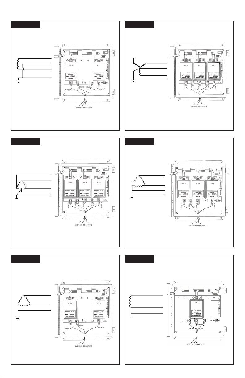
Electrical Connection Diagrams
}
}
Figure 8 Figure 9
Hot (BLK)
V
}
Neutral (WHT)
}
V
Hot (BLK)
Ground (GRN)
SPLIT
2 Hots, 1 Neu, 1 Grnd
Phase A (BLK)
B
A
N
V
}
C
WYE
3 Hots, 1 Neu, 1 Grnd
Figure 10 Figure 11
Phase A (BLK)
Phase B (ORNG)
V
}
Phase C (BLK)
Neutral (WHT)
Ground (GRN)
HI-LEG DELTA (B High)
3 Hots, (B HIGH),
1 Neu, 1 Grnd
V
DE LTA
3 Hots, 1 Grnd
Phase B (BLK)
Neutral (WHT)
Phase C (BLK)
Ground (GRN)
Phase A (BLK)
Phase B (BLK)
Phase C (BLK)
Ground (GRN)
Figure 12 Figure 13
Phase A (BLK)
V
CORNER GROUND
DELTA (B grounded)
2 Hots, 1 Grnd
8
Phase C (BLK)
Ground (GRN)
V
}
SINGLE POLE
1 Hot, 1 Neu, 1 Grnd
Hot (BLK)
Neutral (WHT)
Ground (GRN)
 Loading...