

Page 1
TWL S eries Installation Guide
Tower Light Controller Protectors
Also See TWL Datasheet and Configuration Sheet
The TWL Surge Suppressor is probably different than anything you have seen before.
You will save substantial installation time & rework by understanding the intent behind its
design & installation. Each individual installation is likely to approach a custom installation.
There is reasonable chance that a design team congured and ordered the TWL, as well as multiple individual Surge Protective
Devices (SPDs). Please take a few moments to understand the TWL’s function and the application of each individual SPD.
The TWL is a high quality, high energy, surge suppressor hub assembly. Individual SPDs are connected to the TWL. The purpose
of the TWL is to provide a common ground reference point for individual SPDs, thus ensuring maximum protection to the tower
lighting controller. The TWL also provides the most cost effective ground-level surge protection to uptower lighting equipment.
The TWL is designed to use off-the-shelf APT SPDs in a modular manner. Individual SPDs can be replaced, added to, or eld
retrot. APT SPDs are extremely robust and readily available in a broad application range. This avoids one-off units, which
create cost and availability barriers, and avoids obsolescence issues.
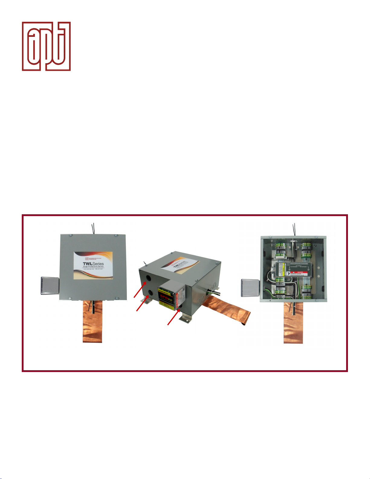
Mounting holes for
additional SPDs.
4 mounting locations
located on opposite side.
Cover in place
For demonstration purposes, the standard TWL pictured above is displayed with one SPDee on left side, AC Power AC XCS inside and with copper ground strap - not included.
Thank you for choosing an APT TWL Surge Protective Device (SPD). Proper installation is important to maximize performance.
Please follow steps outlined herein. These instructions are not intended to replace national or local codes. Follow all applicable
electrical codes to ensure compliance.
TWL may include several different voltage SPDs including AC and DC voltages. Incorrect initial installation may
result in immediate SPD failure upon start up, not covered by warranty, and/or ineffective surge protection.
APT Welcomes Questions & Pre-installation Discussion at 800.237.4567 or [email protected].
Side view
Cover removed
Page 2

WARNING – IMPORTANT – PLEASE READ – WARNING
Safety First – Hazardous Voltage & Shock Hazard
• Only qualied licensed electricians should install or service SPDs
• Hazardous voltages exist within SPDs
• SPDs should never be installed or serviced when energized
• Use appropriate safety precautions including Personal Protection Equipment
• Failure to follow these instructions can result in death, serious injury, and/or equipment damage
• This manual shall be read in entirety prior to installing
Bonding and Grounding Hazard
Verify that the neutral conductor in the AC voltage service entrance equipment is bonded to ground in accordance
with guidelines established by the National Electric Code (NEC®). This is intended to provide the power system with
a dened reference to ground.
There may be circumstances where the Authority Having Jurisdiction (AHJ), for example, a DOT, supercedes the NEC
and or local codes. We caution that deviations from North American, industry-accepted bonding & grounding and surge
suppression techniques may yield undesirable and unexpected results.
Verify that the neutral terminal (XO) on the secondary side of distribution transformers are grounded to the system
ground in accordance with the NEC® and all applicable codes.
During installation into an electrical system, the SPD must not be energized until the electrical system is completely
installed, inspected and tested. All conductors must be connected and functional including the neutral (if required).
The voltage rating of the SPD and system must be veried before energizing the SPD.
Failure to follow these guidelines can lead to abnormally high voltages at the SPD. This may cause the SPD to fail. The
warranty is voided if the SPD is incorrectly installed and/or if the neutral conductor in the service entrance equipment
or downstream of separately derived systems is not bonded to ground in accordance with the NEC®.
Do Not Hi-Pot Test SPDs
Any factory or on-site testing of power distribution equipment that exceeds normal operating voltage such as highpotential insulation testing, or any other tests where the suppression components will be subjected to higher voltage
than their rated Maximum Continuous Operating Voltage (MCOV) must be conducted with the SPD disconnected from
the power source. The neutral connection at the SPD must also be disconnected prior to performing high-potential
testing and then reconnected after test completion.
Failure to disconnect SPD and associated components during elevated voltage testing will damage the SPD and will
void the warranty.
(APT is unaware of any SPD manufacturer that permits Hi-Pot testing of SPDs.)
Page 3

Table of Contents
PRE-INSTALLATION & PLANNING .........................................................................................................................1
INSTA LLATION .........................................................................................................................................................2
Step 1 - Verify that all correct components are in hand: ........................................................................................................... 2
Step 2 - Identify appropriate mounting location for TWL (See Figure 1) ................................................................................... 3
Step 3 - Mount TWL to Wall ....................................................................................................................................................... 3
Step 4 - Connect 4” copper ground strap to TWL (Figure 2)......................................................................................................3
Step 5 - Run wire bundles into TWL, MARKING ALL conductors ..............................................................................................3
Step 6 - Connect individual SPDs ..............................................................................................................................................3
PHOTOCELL SPD (FIGURES 3,4 & 5) ..................................................................................................................... 5
INDIVIDUAL LIGHT SPD(S) (FIGURE 6) .................................................................................................................. 7
AC POWER SPD (FIGURE 7)...................................................................................................................................8
Step 7 Double check work – Label conductors & SPDs - Energize Tower Light Controller .......................................................9
ADVANCED TOPICS ...............................................................................................................................................9
REMOTE SPD DIAGNOSTIC INDICATION .............................................................................................................9
FIGURES
FIGURE 1: You will Need Sufcient Space on Wall for TWL & SPDs ......................................................................2
FIGURE 2: Ground Strap Attachment .......................................................................................................................4
FIGURE 3: Photocell SPD Mounting Location .......................................................................................................... 5
FIGURE 4: Standard Photocell SPD Installation ...................................................................................................... 6
FIGURE 5: Optional SPD Installation .......................................................................................................................6
FIGURE 6: Individual Light SPDs .............................................................................................................................7
FIGURE 7: AC Power SPD .......................................................................................................................................8
FIGURE 8: Bonding Multiple TWLs Together ...........................................................................................................9
Questions?? Need Assistance?? Contact APT at 800.237.4567 or [email protected].
Page 4

INSTALLATION PRE-PLANNING OVERVIEW:
This Surge Suppressor is probably different than anything you have seen before. You will save substantial installation time
& rework by understanding the intent behind its design and installation.
• Need to meet all applicable Codes and Regulations
• Intended for indoor use – If outdoor, the TWL assembly can be mounted in an appropriate weather-resistant
enclosure with appropriate weathertight sealing apparatus.
• Intended to be a central grounding hub for multiple individual SPDs
• There will be multiple conduits and wiring to and from the TWL
• Need appropriate wall space. There will probably be multiple SPDs attached to the side of the TWL – do not try
to cram into too small of space
• Need appropriate path to ground grid or ground – intended to use 4” copper ground strap to connect to existing
grounding grid. This path needs to be straight line, not bends or kinks.
• TWL was intended for wires to enter one side of the TWL and exit the opposite side:
- AC Power – Intended to come from upstream service entrance SPD, enter the TWL, connect to TWL-housed AC power
SPD, and conductors exit TWL to the Tower Light Controller.
- Photocell – Intended for lead from photocell to enter the DIN Rail mounted SPD, which is a series SPD. The load travels
through this SPD, which is different than the other SPDs, which are parallel-connected. The lead from the SPD goes
to the Tower Light Controller. (This SPD is ‘directional’. If the Unprotected and Protected ends are miss-connected,
the SPD will provide decreased surge protection. Direction is important!)
- Uptower loads: Leads are intended to enter the TWL at the bottom, connect to appropriate SPDs within the TWL, then
the leads exit at the top of the TWL to Uptower.
- There may be more than one way to do this. TWL includes many knockouts for customized appropriate installation.
• Commingling lower and higher voltage lines – Follow all applicable Codes
Following may be useful:
NEC 300.3(C) Conductors of Different Systems.
(1) 600 Volts, Nominal, or Less. Conductors of circuits rated 600 volts, nominal, or less, ac circuits, and DC circuits
shall be permitted to occupy the same equipment wiring enclosure, cable, or raceway. All conductors shall have
an insulation rating equal to at least the maximum circuit voltage applied to any conductor within the enclosure,
cable, or raceway.
NEC 800.53 Lightning Conductors. Where practicable, a separation of at least 1.8 m (6ft) shall be maintained
between communication wires and cables on buildings and lightning conductors.
NEC 800.133 – Communication Conductor Separation from Other Conductors
Page 1
Page 5
INSTALLATION
1. Verify that all correct components are in hand:
• TWL: This is effectively an assembly that SPDs attach to in a modular format.
• AC voltage SPD: Verify correct voltage and number of phases. This will mount perpendicular over the top of the two DIN
Rails. It is raised on stand offs so that wiring can pass underneath it. We recommend that this SPD be installed last so
it remains out of your way.
• Photocell SPD: Verify correct voltage. This will mount on a DIN Rail inside the TWL.
• Individual Light SPDs: Use a voltmeter to check all voltages to ensure correct SPDs.
• Verify correct voltage. Be aware that some strobe lights are DC voltage. Connecting the wrong SPDs to wrong voltages
will fail SPDs at startup.
Not included with TWL or SPDs:
• Conduit, ttings, wire, hardware, etc.
• 4” copper ground strap & ground connections
• Mounting hardware
• Labeling equipment
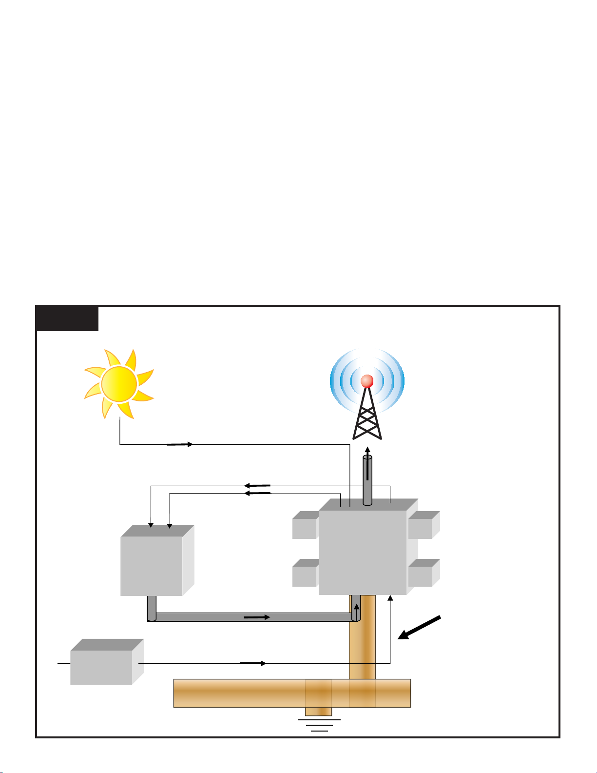
2. Identify appropriate mounting location for TWL (See Figure 1)
Figure 1
You will Need Sufficient Space on Wall for TWL & SPDs
Photocell Conductor
AC Power (Now Surge Protected)
Wire Bundle Going Up-tower
(Now Surge Protected)
Photocell Conductor
(Now Surge Protected)
TOWER
LIGHT
CONTROLLER
TWL & SPDs
AC POWER
SERVICE
ENTRANCE
Unprotected Wire Bundle Going Up-tower
AC Power
Existing Copper Strap
Ground Grid
YOU WILL NEED
SUFFICIENT SPACE
FOR GROUND STRAP
4” Copper Strap
Connection to Ground
Page 2
Page 6

• Presumed indoor use: If outdoor, need appropriately sized outdoor rated enclosure to house TWL and all SPDs.
• Anticipate wiring and conduit into and out of TWL
• AC Power – Intended to come from upstream service entrance SPD, enter TWL hub, connect to TWL-housed AC power
SPD, and conductors exit TWL to Tower Light Controller.
• Photocell – Intended for lead from photocell to enter Unprotected side of DIN Rail mounted SPD. This is a series SPD.
The load travels through this SPD, which is different than the other SPDs, which are parallel-connected. This SPD is
‘directional’. If the Unprotected and Protected ends are miss-connected, the SPD will provide decreased surge protection.
Direction is important!
• Uptower loads: Leads are intended to enter the TWL at the bottom, connect to appropriate SPDs within the TWL, then
the leads exit at the top of the TWL to uptower. Other orientations are possible depending on situation. For example, the
TWL can be mounted sideways if required. The proposed APT SPDs are not direction or orientation sensitive.
• Anticipate ground conductor path to ground grid or ground. Intended to use 4” copper ground strap to connect to existing
grounding grid. This path needs to be straight, no bends or kinks.
• It is physically possible to use large gauge ground wires. However, traditional round wire has much more inductance than
at strap. This hurts performance in surge & lightning protection scenarios. Given a choice, using round wire would be a
mistake. If round wire is unavoidable, we recommend multiple, exactly-parallel ground wires of equal length to minimize
inductive losses.
3. Mount TWL to Wall
• Consider mounting the 4” copper ground strap to an appropriate location on the backside of the TWL before mounting
the TWL to the wall. This may be easier, see #4 below.
• Mount TWL to wall using the four attachment holes on the aluminum baseplate. Use appropriate attachment hardware
(not included).
• Ensure that 4” copper ground strap is installed and robustly connected to ground system. Failure to provide reliable
ground will defeat the purpose of the TWL and associated SPDs.
4. Connect 4” copper ground strap to TWL (Figure 2)
Four sets of predrilled holes are provided; one on each side of the TWL. This maximizes effectiveness, eases installation,
and also allows bonding to other equipment if desired. If required, these can be used to bond two TWL’s side by side.
The 4” copper ground strap is intended for installation directly under the aluminum backplane with robust bolts (included).
The aluminum backplane is tin-plated to prevent dissimilar metal cathodic interaction (prevent corrosion).
The backplane is elevated approximately 7/8” to provide working access. Torque connections to 7 lb-ft. Ensure that ground
strap is not ripped or torn during installation.
5. Run wire bundles into TWL, MARKING ALL conductors
• Use appropriate care to separate wires into separate conduit(s). Use appropriate conduit and connectors to the TWL.
• It may be appropriate to provide separate conduit(s) for AC power and/or the photocell (if equipped).
6. Connect individual SPDs
• We suggest installing SPDs in the following order:
- 1. Photocell – do this rst to get it out of the way
- 2. Individual light SPD(s) (there may be several)
- 3. AC power SPD – do this last because it will cover the work area making work on other units more difcult
Page 3
Page 7
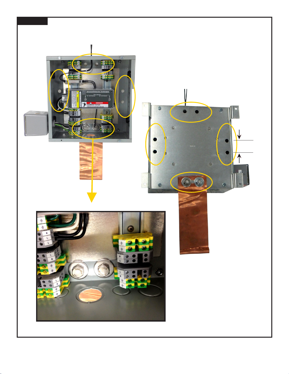
Figure 2
Ground Strap Attachment
Bolt holes for installers' ease of
installation. Use appropriate pair of bolts.
1 3/4" Typical
4" copper clad strap mounts
under the aluminum backplane.
(Aluminum backplane is tin-plated
for dissimilar metal reasons and
corrosion resistance)
(1/2" / 13 x 1" Bolts - Qty 2)
Questions?? Need Assistance?? Contact APT at 800.237.4567 or [email protected].
Page 4
Page 8
PHOTOCELL SPD (FIGURE 3, 4 & 5)
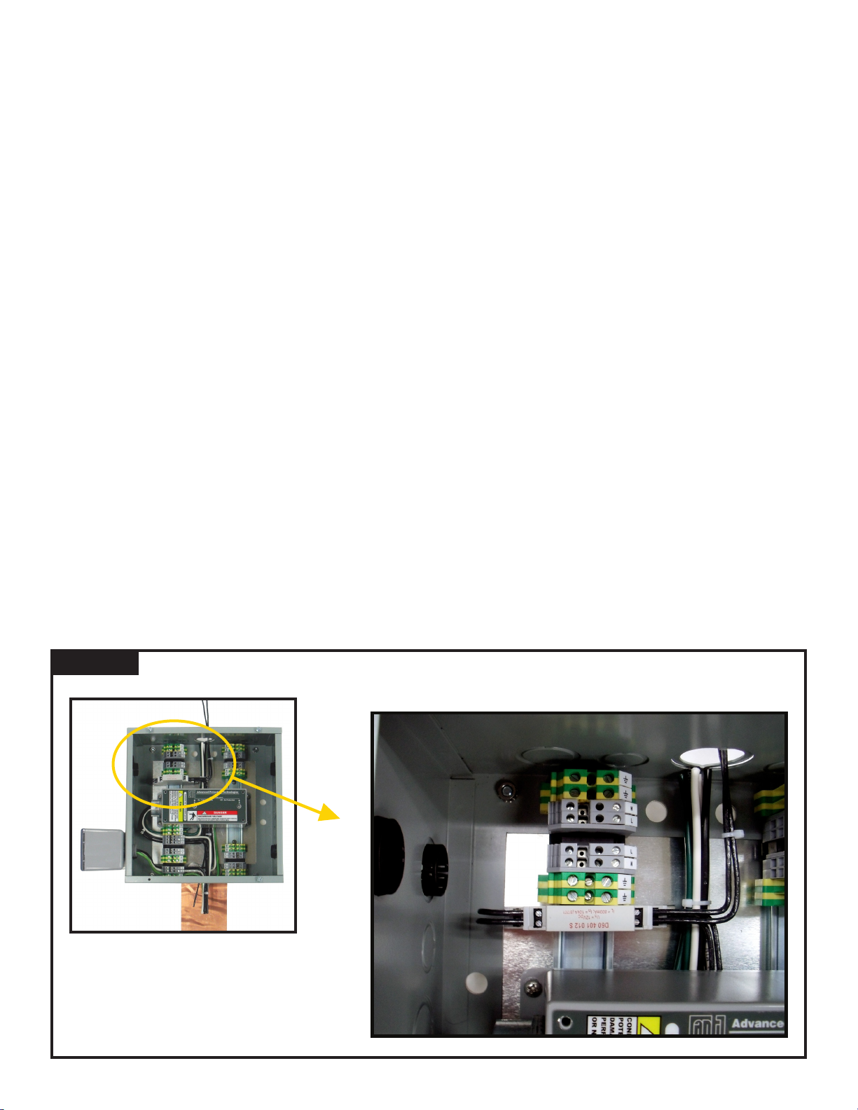
• Identify an appropriate mounting location for the photocell SPD
• We suggest the less-populated area of DIN Rail opposite the intended connection of the AC voltage SPD (because there
will be more space) (Figure 3)
• Identify the SPD’s Unprotected and Protected ends. This SPD is directional. The Unprotected side needs to be wired to
the photocell. The Protected side needs to be wired to the tower light controller. Reversal will result in ineffective surge
protection. (Figure 4) Also see Alternate Installation below.
• Note that this is a series, in-line connected SPD. The signal goes through the SPD. Connection of this SPD will not
consume any of the existing feed-through terminal blocks.
• Mount the SPD on the DIN Rail
• Connect Unprotected side of SPD to photocell in appropriate conduit
• Connect Protected side of SPD to tower light controller in appropriate conduit
• Make sure SPD is properly secured to DIN Rail as that connection is the ground path for this SPD. A secondary ground
connection may be added from the SPD’s ground terminal to the aluminum backplane.
Alternate Installation (Figure 5): The APT SPD includes surge protection for two (2) different sets of conductors. If you only
have one (1) set of conductors, the SPD can be wired in a manner that provides redundant or cascade protection through
the second surge suppression path. (There is a remote possibility that the impedance of the second suppression path can
interfere with the signal. If this occurs, revert to standard installation above.)
APT DIN rail SPDs are actually two separate SPD circuits in the same package. Rather than use one circuit and abandon
the other circuit, you can use both of them in a cascade manner. This provides redundancy at no extra cost – surge goes
through the two suppression circuits within the one SPD. (This is usually a good idea for any circuit!)
There is an ‘Unprotected’ side and a ‘Protected’ side. (The ‘Unprotected’ side has the ground lug)
1.) Wire from the Photocell into either Unprotected side,
2.) Loop from one Protected side to the other Protected side,
3.) Wire to the tower light controller from the other Unprotected side.
Note schematic on SPD
Do Not reverse the Unprotected & Protected sides or you will hurt performance.
Figure 3
Photocell SPD Mounting Location
Page 5
Photocell SPD can be mounted
on any open DIN rail area
Page 9
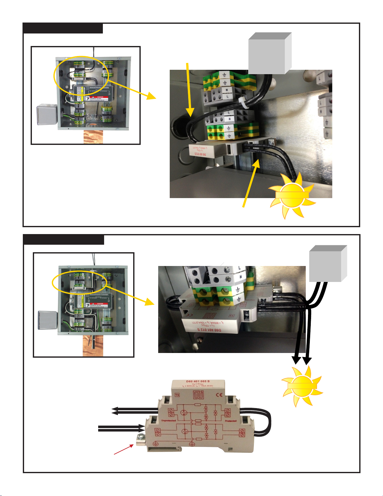
Figure 4
Standard Photocell SPD Installation
Protected
Side
SPD has a Protected and an Unprotected side.
• Unprotected sideshould be towards
photocell.
• Protectedsideshould betowardstower
lightcontroller.
Protected side towards
tower light controller
CONTROLLER
Unprotected side towards photocell
TOWER
LIGHT
PHOTOCELL
Figure 5
To Tower Light
Controller
From Photocell
Optional Photocell SPD Installation
(The orientation of the unit pictured above is upside down)
TOWER
LIGHT
CONTROLLER
PHOTOCELL
Loop on Protected side,
not Unprotected side
The unprotected side has the ground lug
"Protected" side
Note Schematic on side
Page 6
Page 10
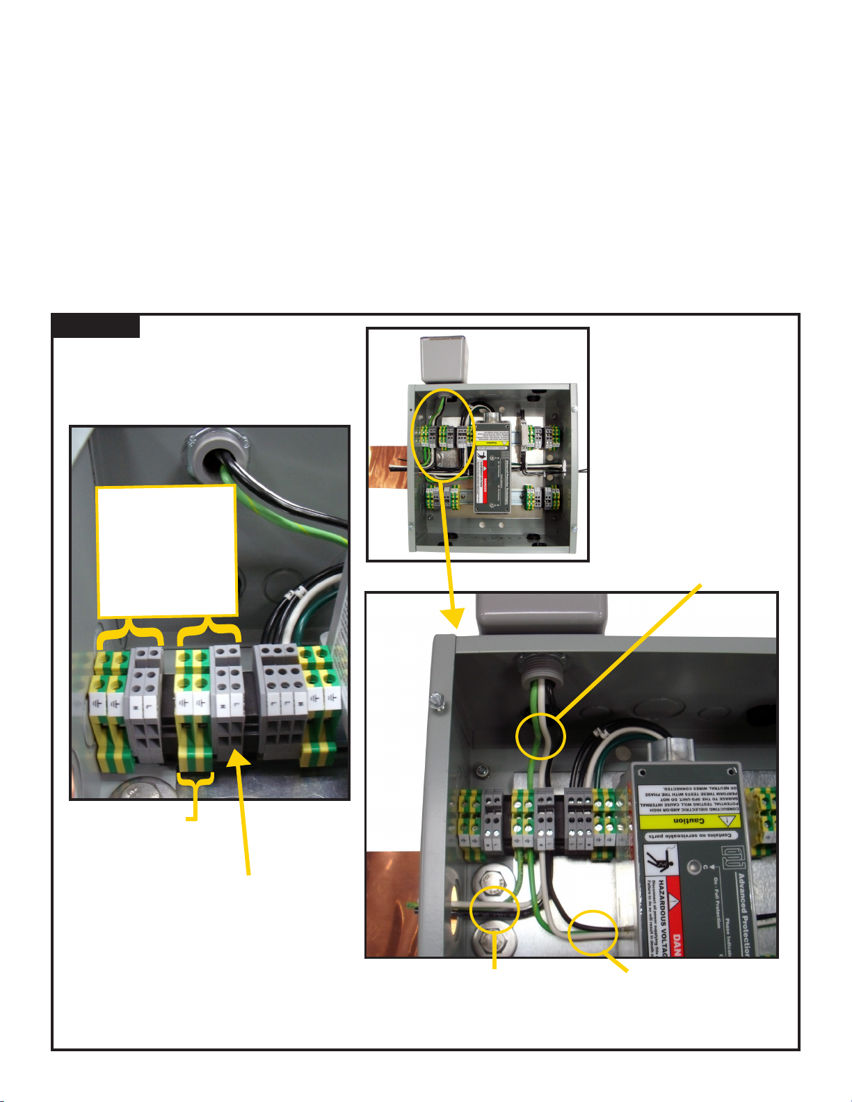
INDIVIDUAL LIGHT SPD(S) (FIGURE 6)
• Identify an appropriate mounting location for each SPD. Notice that there are four pre-drilled holes for APT SPDee’s
on an upper row. (We recommend using upper row rst.) There are also multiple knockouts on a bottom row. Consider
proximity to existing DIN rail connectors.
• Read SPD installation manual.
• Mount SPD to TWL. Notice orientation of LED indicator. Rotate SPD such that LED is visible from front.
• Connect SPD AC-Hot or DC-Positive to terminal block as shown in Figure 6. Torque: 7 lb-in
• Connect SPD AC-Neutral or DC-Negative to terminal block as shown in Figure 6. Torque: 7 lb-in
• Note that both of these are fed through connectors. The load goes in and out of the terminal. The SPD is connected
electrically in parallel, not in series.
• Connect SPD Ground to terminal block as shown in Figure 6. Torque: 7 lb-in
• Congure SPD leads as short and straight as possible. Do Not coil excess leads. Do Not create sharp kinks. Long leads
& sharp bends seriously hurt performance!!
• Repeat for appropriate number of SPDs
Figure 6
Individual Light SPDs
Terminal Blocks without connections
Empty sets of
terminal blocks
(One set per SPD)
Try to use closest set
of terminals to SPD to
keep leads short
SPD connected
Leads from SPD to back
side of terminal block
Two Ground Terminals
are interconnected via
grounded DIN rail
- Connect lead from
controller to one
terminal
- Connect lead to up tower load to the
other terminal
Page 7
Each gray terminal block
has three terminals:
Two terminals are visible
on this side
- one from controller (input)
- one to loads on tower (output)
Leads from controller
into terminal block
block to loads up tower
One terminal on the back side (not visible in this photo) for connecting the SPD
Conductors will go
under the AC Power
SPD (If installed last,
this SPD will not be
in the way)
Leads from terminal
Page 11
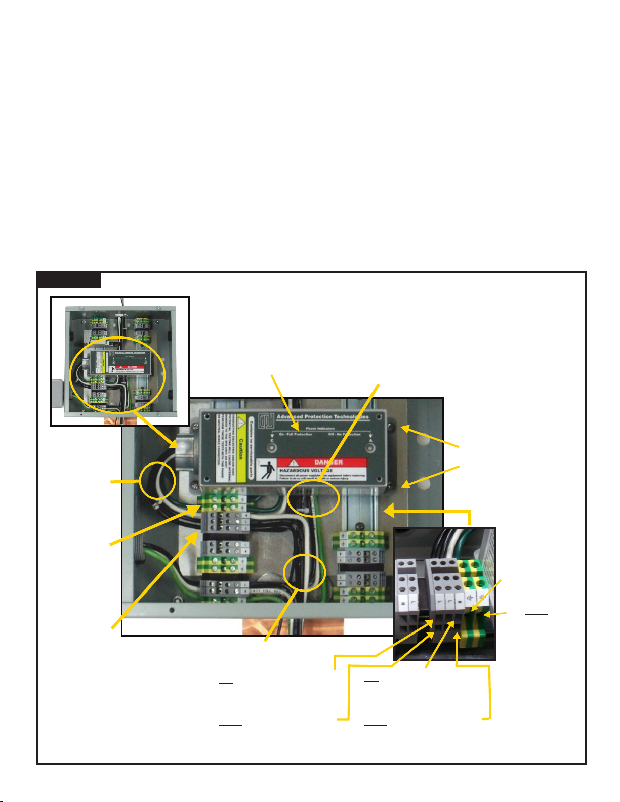
AC POWER SPD (FIGURE 7)
• We suggest installing this last because it mounts over the top of other wiring & circuitry.
• Identify the mounting standoffs. The XCS SPD will mount onto those standoffs.
• Identify the terminal blocks for AC Power SPD. These are immediately adjacent to the SPDs mounting location, and include
one extra terminal for a 120/240V application. (The other pre-congured terminals assume one hot and one neutral. AC
power presumes two hots and one neutral.)
• There may be an existing SPD at the electrical service entrance, grounded at that point. The TWL SPD serves as a
redundant, cascaded SPD, grounded in the TWL at the same point as the other tower light SPDs. Do not eliminate the
TWL AC power SPD under the presumption that the service entrance SPD provides protection.
• Read SPD installation manual.
• Mount SPD such that conductors to terminal blocks are shortest. Inches matter - do not run the conductors across the
TWL to the opposite set of DIN rail connectors. Bolt down SPD to standoffs.
• Connect SPD AC-Hot(s) to terminal block as shown in Figure 7. Torque: 7 lb-in
• Connect SPD AC-Neutral to terminal block as shown in Figure 7. Torque: 7 lb-in
• Note that both of these are feed-through connectors. The load goes in and out of the terminal. The SPD is connected
electrically in parallel, not in series.
• Connect SPD Ground to terminal block as shown in Figure 7. Torque: 7 lb-in
• Congure SPD leads as short and straight as possible. Do Not coil excess leads. Do Not create sharp kinks.
Figure 7
Leads from SPD
to back side of
terminal block
Two Ground
Terminals are
interconnected
because they are
both grounded to
the DIN rail
AC Power SPD
Incoming Power APT
XCS-family SPD
(120/240V split phase
in this example)
Leads from
terminal block
to tower light
controller AC
power input
SPD Mounting Standoffs
G into one terminal
block from service
entrance or AC
power panel
SPD connects to
load conductors
via feed-through
terminal blocks
Leads into terminal blocks from service entrance or AC power panel
L1 & L2 into terminal block from service
entrance or AC power panel
L1 & L2 out of terminal block to tower
light controller AC power input
N into terminal block from service
entrance or AC power panel
N out of terminal block to tower
light controller AC power input
G out of other
terminal block
to tower light
controller AC
power input
(Both Ground
terminal blocks are
connected together
and grounded to
DIN Rail)
Page 8
Page 12
7. Double check work – Label conductors & SPDs - Energize Tower Light Controller
• Double check work – conrm that correct SPDs are installed to correct circuits.
• If in doubt – please contact APT Tech Support at (800) 237-4567.
• Double check torque to 7 lb-in.
• Double check that ground terminals are tight to DIN Rail
• Upon verication that SPDs are installed correctly,
• Label each wire bundle for ease of future service, and label each SPD
• Energize circuits
• Individual SPD LED indicators should illuminate correctly.
• Install TWL cover.
Advanced Topics:
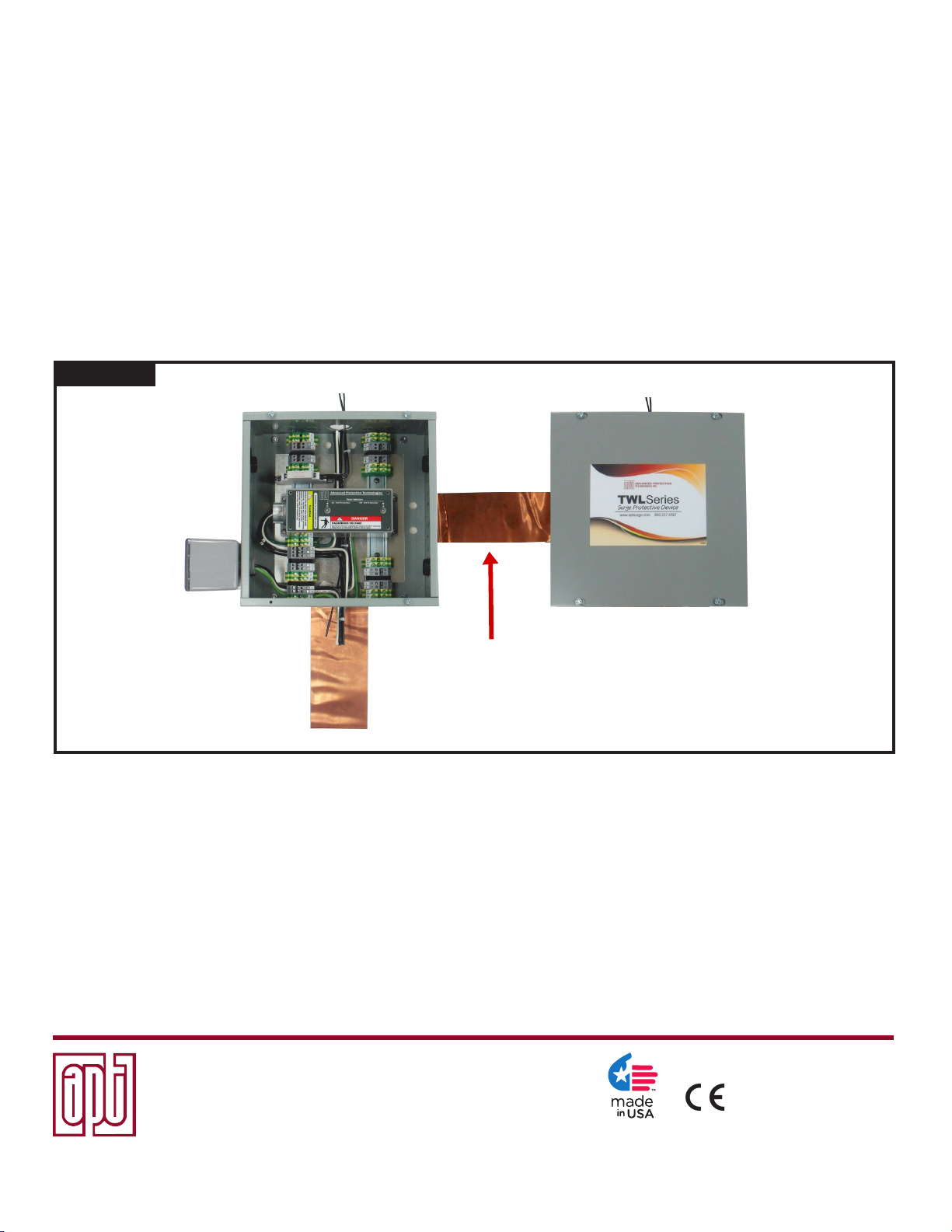
Two TWLs side by side, or one above or below the other. (Figure 8):
Mount appropriately. Ensure solid ground connection between two TWLs via 4” copper ground strap.
Figure 8
Bonding Multiple TWLs Together
4" copper ground strap
interconnects two TWLs
To Ground
Remote SPD Diagnostic Indication:
Most APT SPDs are available with optional Dry Contacts for remote monitoring purposes. These indicate A-OK/Good or Failed
status. See individual SPD datasheets for more information. SPDs must be ordered with this option and cannot be eld retro-t.
When equipped, the SPD includes additional Form C Dry Contact wires. These wires may be connected to additional feedthrough terminal blocks for remote connection elsewhere.
Questions?? Need Assistance?? Contact APT at 800.237.4567 or [email protected].
Advanced Protection Technologies
14550 58th Street North
(800) 237-4567·(727) 535-6339 · Fax (727) 539-8955
www.apttvss.com · [email protected] · www.aptsurge.com
UL is a registered trademark of Underwriters Laboratories, NEC and National Electrical Code are registered trademarks of National Fire Protection Association,
C62.41.1-2002, C62.41.2-2002, C62.45-2002, C62.72-2007 are registered trademarks of IEEE.
Clearwater, Florida 33760
·
European Authorized Representative
Boulevard Général Wahis 53
1030 Brussels, BELGIUM
Tel: +(32) 2. 732.59.54
Fax: +(32) 2. 732.60.03
E-Mail: [email protected]
Obelis s.a.
5.29.12 #8615
Page 9
 Loading...