

Advanced Protection XCS User Manual [en, es]
ENGLISH
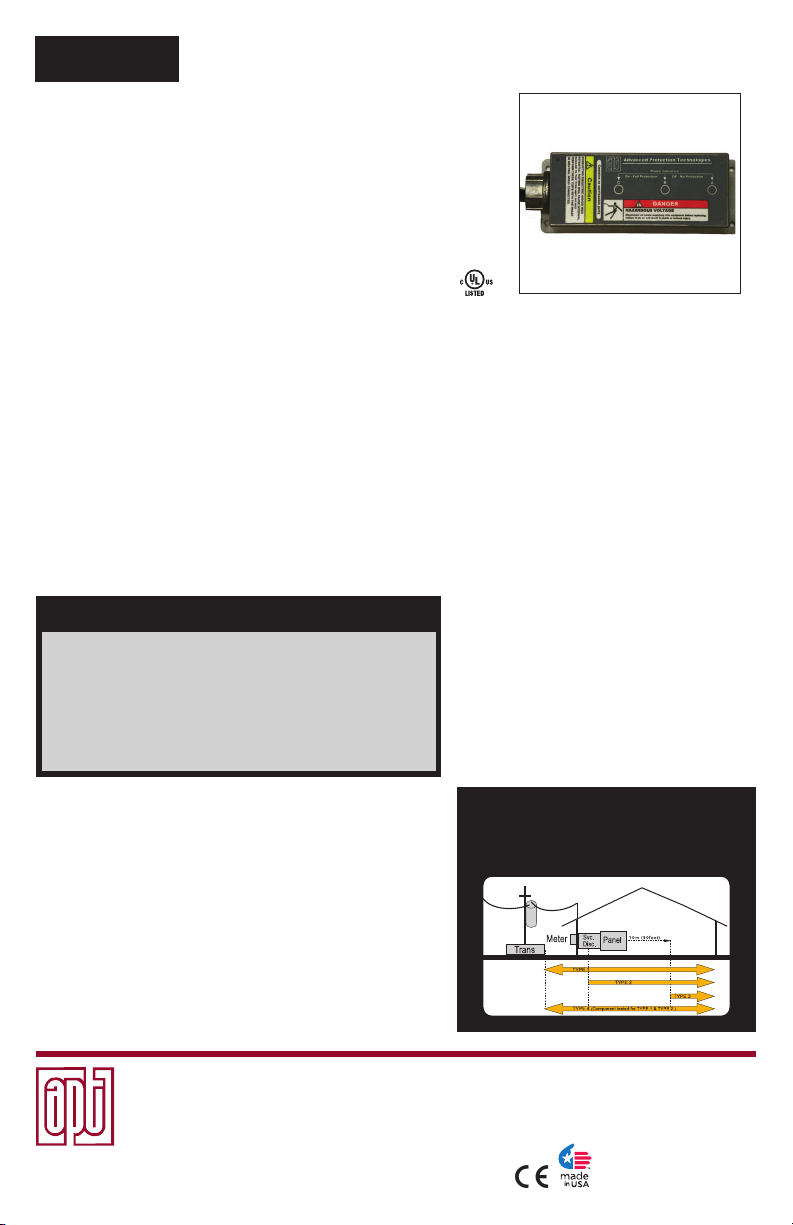
TEXCS Series
Surge Protective Device (SPD)
Installation, Operation
& Maintenance Manual
Thank you for choosing an APT XCS Surge Protective Device (SPD). The XCS is a high quality, high
energy surge suppressor designed to protect sensitive equipment from damaging transient overvoltages.
The XCS is parallel connected such that circuit ampacity is unlimited. Proper installation is important to
maximize performance. Please follow steps outlined herein. These instructions are not intended to replace
national or local codes. Follow all applicable electrical codes to ensure compliance.
UL 1449 Third Edition (Sept 2009) and 2008
WARNING
▪Only qualied licensed electricians should install or service SPDs
▪SPDs should never be installed or serviced when energized or during electrical storms
▪Use appropriate safety precautions including Personal Protection Equipment
▪Failure to follow these instructions can result in death, serious injury, and/or
equipment damage
▪When used in outdoor applications, customer must seal the conduit nipple using
watertight ttings (not included) to ensure a watertight connection
▪Read this manual in its entirety prior to installing
– Risk of Electric Shock
®
NEC
Article 285 generated substantial
changes regarding SPDs.
The X CS complies with latest regulatory
actions and is UL 1449 Listed as such
(VZCA.E321351). There is new emphasis on
installation location, identied as Types 1, 2,
3 and 4, outlined below.
SPD Types (see 2008 NEC® Article 285 and/or UL 1449-3):
Type 1: Installation on the line side or load side of the service
disconnect overcurrent device and may be used in Type 2 or Type
4 installations. Examples: surge arrestors, lightning arrestors,
meter hubs, metering cabinets, ran out of breaker positions, etc..
Type 2: Downstream of service disconnect; probably will
connect via breaker. Examples: switchboards, power panels,
panelboards, equipment, motors, pumps, etc.
Type 3: Plug-in SPD
Type 4:
Usually treated as a UL Recognized component in a larger
UL Listed nished product. Examples: UL 508 control panels, medical
equipment, wind turbines, signage, conveyers, elevators, etc.
Advanced Protection Technologies
14550 58th Street North
(800) 237-4567·(727) 535-6339 · Fax (727) 539-8955
UL is a registered trademark of Underwriters Laboratories, NEC® and National Electrical Code are
registered trademarks of National Fire Protection Association, C62.41.1-2002, C62.41.2-2002,
C62.45-2002, C62.72-2007 are registered trademarks of IEEE.
www.aptsurge.com · info@aptsurge.com
· Clearwater, Florida 33760
NEC® Article 285 & UL 1449-3
SPD Types: Types 1, 2, 3, & 4
Based on Location within electrical distribution system
(also coincides with ANSI/IEEE C62.41.2 - 2002 Categories C, B &A)
European Authorized Representative
Boulevard Général Wahis 53
1030 Brussels, BELGIUM
Fax: +(32) 2. 732.60.03
E-Mail: mail@obelis.net
Obelis s.a.
Tel: +(32) 2. 732.59.54
7.9.13.lh #8078
INSTALLATION
Pre-Plan your installation. You need to accomplish the following:
▪ Meet all National and Local codes (NEC
▪ Conrm System voltage to SPD voltage (120V SPD will fail instantly on 240V, 277V, etc.).
▪ Mount SPD as close to panel or equipment as possible to keep leads short.
▪ Ensure leads are as short and straight as possible, including neutral and ground. If using a
breaker, use a breaker position that is close to the SPD and the panel’s neutral and ground.
▪ If using a breaker, recommended breaker size is 30A due to 10 AWG conductor.
▪ Make sure system is grounded per NEC
(inadvertent system problem may fail SPD).
▪ Never Hi-Pot test Any SPD. (will prematurely fail SPD).
▪ Do not install the XCS through the bottom of a NEMA 3R panel. Dripping water will
prematurely fail the SPD.
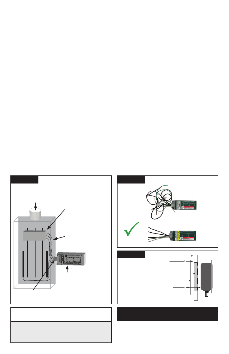
1. Use voltmeter to check voltages and ensure correct SPD. See Data Sheet for specs and wire-outs.
2. Determine Mounting location – weather resistant equipment may be required.
3. If SPD has optional Dry Contact Flush Mount Kit, or Remote Indicator, pre-plan their installation. See
Figure 3. (If ush mounting, be careful to not drop SPD into wall).
4. Remove power from panel/source. Conrm panel/source is deenergized.
5. Identify breaker location and SPD location. Position SPD such that LEDs are best visible.
6. Mount SPD – weather resistant applications require additional sealing, etc. (not included)
- Remove an appropriately sized knockout from panel.
- Connect conductors as appropriate – short and straight as possible (Hi-Legs are Phase B).
- Note that the metallic connection hub is not grounded within the SPD and proper grounding
requires connection of the green conductor ground.
7. Label or mark conductors as appropriate (neutral: white, ground: green, energized: black, hi-leg: orange).
8. Make sure system is bonded per NEC® and is clear of hazards or faults before energizing
(N-G bonding not per NEC® will fail SPDs: #1 cause of SPD failures).
9. Energize and conrm proper operation of green LED indicators and/or options.
®
Article 285 and UL 1449 address SPDs).
(long leads hurt performance).
®
and clear of faults before energizing SPD.
Figure 1
TYPICAL PANEL
INSTALLATION
(Type 1 or individual equipment installations may vary)
To Protected Loads
BC
A
BREAKER
GN
▪
Outdoor installation requires appropriate weather
sealing at nipple (gasket, sealing conduit, etc.)
V
WARNING
▪
Use closest breaker
to SPD
▪
Locate SPD close to
intended breaker
▪
Keep Leads Short
as Possible
▪
Avoid Sharp Bends
▪
Rotate XCS such
that LED indicator is
most visible
▪ Conrm XO N-G Bonding at Upstream Transformer
▪ Do Not Hi-Pot Test
▪ Resulting Damage is not Covered Under Warranty
2
Figure 2
X
NOT
GOOD
GOOD
Figure 3
Insert ushmount screw
through hole in each
corner or punch a small
starting hole in center of
each translucent window
(located in all 4 corners
of the label).
V
VERIFY THAT ALL POWER CIRCUITS ARE
DEENERGIZED BEFORE MAKING CONNECTIONS
All electrical connections should be performed by a qualied (licensed)
electrician or technician. All wiring must comply with the National
Electrical Code (NEC
LEADS SHORT & STRAIGHT
Mounting Surface
Mounting
Screws
(4 places, through mountingplate into
mounting surface, screws not provided)
Removed Material
Flush Mount Plate
Flush Mount
Kit Screws
(8-32 x 5/8” Thread Cutting, 4
places, through plate into SPD)
WARNING
®
) and applicable local codes.
Cut off
Excess
Length
Do Not
Loop or
Coil
Short and
Straight
SPD
Phase, Ground,
and Neutral Wires
The XCS is a Type 1 SPD. The XCS is suitable
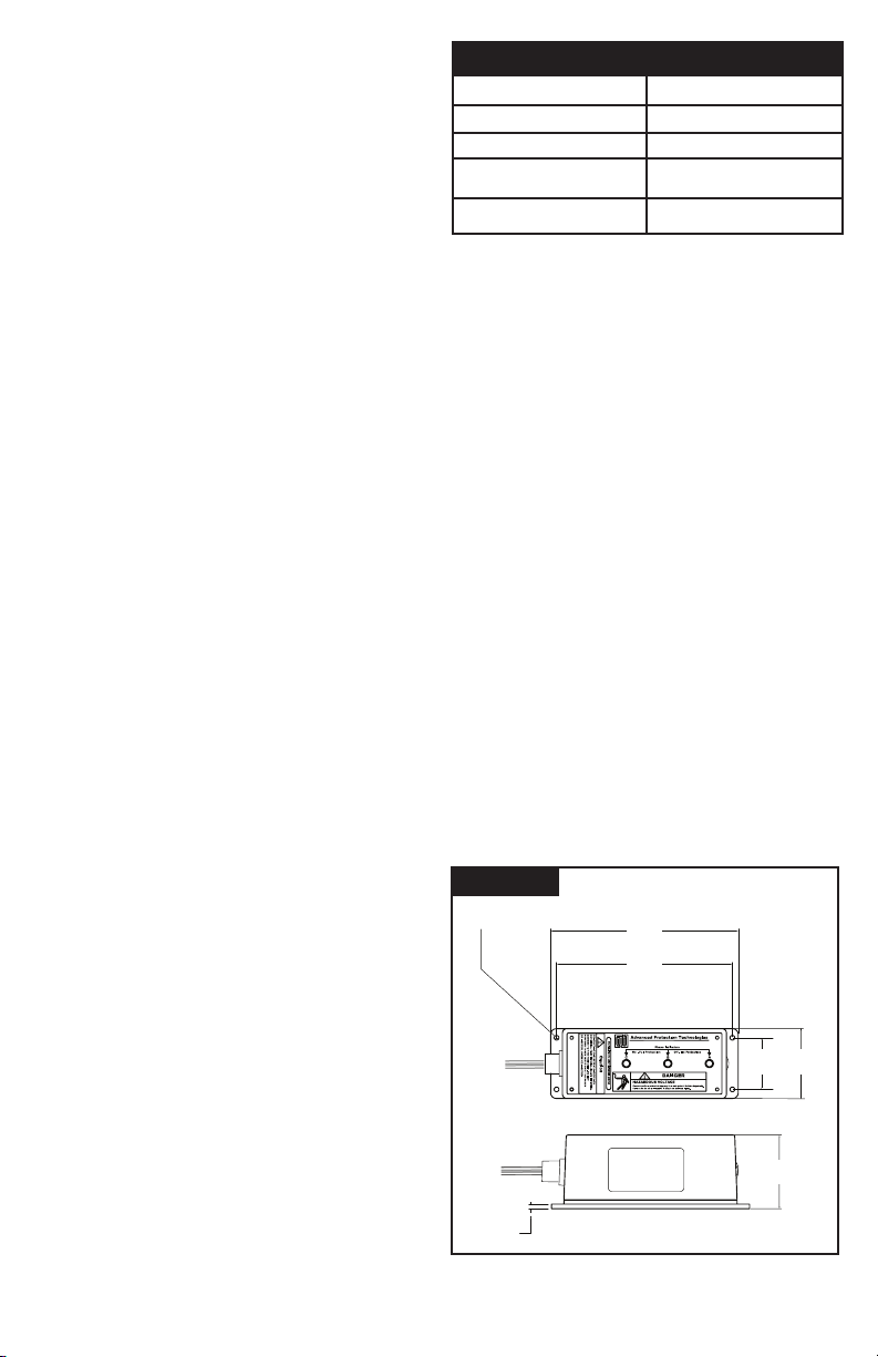
3.00"
.183"
7.91"
7.41"
∅
.201"
2.21" 3.00"
for use almost anywhere (not as a plug-in SPD).
Type 1 SPDs are evaluated more rigorously by UL
1449 for 2008 NEC
®
Article 285 compliance. Type
1 SPDs and their connecting leads have been
evaluated for line side applications without need
for supplemental overcurrent protection. Type 1
SPDs include internal overcurrent protection. As
a generalization, there are practical maintenance
reasons for installing on the load side of the main
overcurrent device (i.e. Type 2 installation). When
connected on load side of main disconnect, we
recommend connecting via a 30A circuit breaker
due to 10 AWG conductors. The circuit breaker
serves as a disconnect switch and provides NEC®
imposed short circuit protection to the conductors
in Type 2 or 4 applications. (cUL models are Type
2 due to different cUL criteria.)
Simplified Explanation of Operation: SPDs
sense overvoltage and create a momentary short
circuit to redirect harmful surge energy to earth
ground. They reset automatically and wait for the
next surge. This is similar to the pressure relief
valve on a water heater: pressure goes up, valve
opens to relieve pressure and then resets. In an
electrical system, an SPD senses overvoltage,
shorts temporarily sending energy to ground and
then resets. SPDs are capable of repeating this
function thousands of times.
Parts List
1 - XCS suppressor including 3’ (~1m) conductors
1 - Installation Sheet (this document)
1 - Data Sheet (attached)
If the Flush Mount Kit was ordered,
additional parts include:
1 - Flush Mount Plate
4 - Mounting Screws
*See Figure 3 For Installation
Specications
Temperature Operating -40oC (-40oF) to 60oC (+140oF)
o
Temperature Storage -55
Wire Size & Installation Torque 10 AWG; 18 inch-pounds
Appropriate Circuit Breaker
based on conductor size
NEMA 250 Enclosure Rating
Voltage Rating & Application
Before installing SPD, verify by nameplate voltage
or model number that it has the same voltage rating
as the power distribution system. See attached Data
Sheet or call APT Tech Support at (800) 237-4567
as appropriate. The SPD’s specier or user should
be familiar with the conguration and arrangement
of the power distribution system. The system is
defined by how the secondary windings of the
transformer supplying the service entrance main or
load are congured. This includes whether or not
the transformer windings are referenced to earth via
a grounding conductor. The system conguration is
not based on how any specic load or equipment is
connected to a particular power distribution system.
SPDs should be installed per the distribution system,
not per a load or motor’s wiring connection.
For example, suppose a 480V three phase motor
appears to be connected as a 480V Delta. In
actuality, the serving distribution system might
be a 480Y/277V grounded Wye, with or without a
neutral pulled to the motor or MCC. The system
is still a 480Y/277V Wye, even though the load
is connected as a Delta. A grounded Wye has a
dened reference to ground (i.e., neutral is bonded
to ground). In contrast, some Delta systems are
ungrounded, which have no reference to ground.
Figure 4
DIMENSIONS & WEIGHT
C (-67oF) to 65oC (+149oF)
30A (SPD includes internal OCP)
Type 4X with appropriate
sealing and sealing conduits
Most XCS have demonstrated 200kA or 100kA
Short Circuit Current Ratings (SCCR) including
leads. See UL Label markings on SPD or see
Data Sheet for specs.) Supplemental overcurrent
protection is not required to protect this SPD.
However, NEC® convention requires that connecting
conductors have overcurrent protection in Type 2 or
4 applications. Follow applicable codes.
This device features internal overcurrent and
overtemperature protection that will disconnect
effected surge suppression components at the
end of their useful life, but will maintain power
to the load – now unprotected. If this situation
is undesirable for the application, follow these
instructions for replacing the device. XCS is
ultrasonically welded closed and contains no user
serviceable parts.
3
 Loading...