

Advanced Energy Paramount User Manual

Paramount® Plus Generators
User Manual
November 2018 57023942-00E
Advanced Energy
®
Paramount® Plus Generators
COPYRIGHT
This manual and the information contained herein are the proprietary property of Advanced
Energy Industries, Inc.
No part of this manual may be reproduced or copied without the express written permission of
Advanced Energy Industries, Inc. Any unauthorized use of this manual or its contents is
strictly prohibited. Copyright © 2014-2018 Advanced Energy Industries, Inc. All Rights
Reserved.
DISCLAIMER AND LIMITATION OF LIABILITY
The information contained in this manual is subject to change by Advanced Energy
Industries, Inc. without prior notice. Advanced Energy Industries, Inc. makes no warranty of
any kind whatsoever, either expressed or implied, with respect to the information contained
herein. Advanced Energy Industries, Inc. shall not be liable in damages, of whatever kind, as
a result of the reliance on or use of the information contained herein.
PRODUCT USAGE STATEMENT
WARNING:
Read this entire manual and all other publications pertaining to the work to
be performed before you install, operate, or maintain this equipment. Practice
all plant and product safety instructions and precautions. Failure to follow
instructions can cause personal injury and/or property damage. If the
equipment is used in a manner not specified by the manufacturer, the
protection provided by the equipment might be impaired. All personnel who
work with or who are exposed to this equipment must take precautions to
protect themselves against serious or possibly fatal bodily injury.
Advanced Energy Industries, Inc., (AE) provides information on its products
and associated hazards, but it assumes no responsibility for the after-sale
operation of the equipment or the safety practices of the owner or user.
NEVER DEFEAT INTERLOCKS OR GROUNDS.
TRADEMARKS
All Advanced Energy trademarks are the property of Advanced Energy Industries, Inc. For
the list of Advanced Energy trademarks, visit: http://www.advanced-energy.com/en/
Trademarks.html. Any unauthorized use of Advanced Energy trademarks is prohibited.
57023942-00E ii

Advanced Energy
®
All other trademarks are the property of their respective owners.
CUSTOMER FEEDBACK
Advanced Energy’s technical writing staff has carefully developed this manual using
research-based document design principles. However, improvement is ongoing, and the
writing staff welcomes and appreciates customer feedback. Please send any comments on the
content, organization, or format of this user manual to:
• tech.writing@aei.com
To order a manual, please contact Technical Support:
• technical.support@aei.com
Paramount® Plus Generators
57023942-00E iii

Advanced Energy
®
Paramount® Plus Generators
Table of Contents
Chapter 1. Safety and Product Compliance Guidelines
Important Safety Information ................................................................................. 1-1
Using This Manual ......................................................................................... ....... 1-1
Danger, Warning, and Caution Boxes ................................................................... 1-2
Safety Guidelines .................................................................................................. 1-3
Rules for Safe Installation and Operation ....................................................... 1-3
Interpreting Product Labels ................................................................................... 1-3
Product Compliance .............................................................................................. 1-5
Product Certification ................................................................................ ....... 1-5
Safety and EMC Directives and Standards ............................................. ....... 1-5
Conditions of Use .................................................................................... ....... 1-5
Environmental Compliance ............................................................................. 1-6
Chapter 2. Product Overview
Platform Description .............................................................................................. 2-1
Theory of Operation ....................................................................................... ....... 2-1
Operation Overview ........................................................................................ 2-1
AC Input .......................................................................................................... 2-2
DC Switching Mode Power Supply ................................................................. 2-2
RF Section ...................................................................................................... 2-2
Logic/Control Section .............................................................................. ....... 2-2
Chapter 3. Specifications
Specifications ........................................................................................................ 3-1
Chapter 4. Communication Controls
Basic LED Status Display .............................................................................. ....... 4-1
25-Pin User Port .................................................................................................... 4-2
25-Pin User Port Connector .................................................................... ....... 4-2
Satisfying Minimal Requirements for the 25-Pin User Port ..................... ....... 4-2
25-Pin User Port Cabling Requirements ................................................. ....... 4-3
Apex Compatible 25-Pin User Port ................................................................. 4-3
Pin Descriptions for Apex Compatible User Port .............................. ....... 4-3
Wiring Diagrams for Apex Compatible User Port ..................................... 4-7
Custom 15-Pin User Port ............................................................................... ..... 4-12
Custom 15-Pin User Port Connector ....................................................... ..... 4-12
Satisfying Minimal Requirements for the Custom 15-Pin User Port ........ ..... 4-13
57023942-00E ivTable of Contents

Advanced Energy
®
Paramount® Plus Generators
Custom 15-Pin User Port Cabling Requirements .................................... ..... 4-13
Custom 15-Pin User Port Signal and Pin Descriptions ................................. 4-13
Pin Description Table ............................................................................. 4-13
Wiring Diagrams for Custom 15-Pin User Port ................................. ..... 4-16
AE Bus Interface (Host Port) ............................................................................... 4-19
Host Connector ............................................................................................. 4-20
Host Port Pin Descriptions ............................................................................ 4-20
AE Bus Transmission Parameters ................................................................ 4-21
Host Port DIP Switches ........................................................................... ..... 4-22
DIP Switch and Switch Settings ............................................................. 4-22
Switches ................................................................................................. 4-22
Setting the Baud Rate ............................................................................ 4-22
Setting the Communication Mode .......................................................... 4-23
Setting the Unit AE Bus Address ...................................................... ..... 4-23
AE Bus Protocol ...................................................................................... ..... 4-24
AE Bus Header Byte ......................................................................... ..... 4-25
AE Bus Command Number Byte ...................................................... ..... 4-25
AE Bus Optional Length Byte ........................................................... ..... 4-25
AE Bus Data Bytes ........................................................................... ..... 4-26
AE Bus Checksum Byte ......................................................................... 4-26
Creating an Ideal Communications Transaction ........................................... 4-27
T0: Host Transmits Message Packet ................................................ ..... 4-27
T1: Unit Verifies Host Transmission Packet ........................................... 4-27
T2: Unit Transmits Response to Host ............................................... ..... 4-28
T3: Host Acknowledges Unit Response ................................................. 4-28
AE Bus Communications Transaction Example ............................... ..... 4-28
Ethernet Interface ................................................................................................ 4-29
Ethernet Connector and Indicators ............................................................... 4-29
Ethernet Port Pin and Signal Descriptions .............................................. ..... 4-30
TCP Protocol (FC100) ............................................................................. ..... 4-30
Establishing a Connection ................................................................ ..... 4-30
Data Encoding .................................................................................. ..... 4-31
Using FC100 ................................................................................................. 4-32
FC100 Send Packet Format ............................................................. ..... 4-32
FC100 Response Packet .................................................................. ..... 4-33
FC100 Error Packets ........................................................................ ..... 4-33
FC100 Example ................................................................................ ..... 4-34
AE Host Commands ............................................................................................ 4-35
AE Host Command Status Response (CSR) Codes ............................... ..... 4-36
AE Host Command Set ........................................................................... ..... 4-37
PROFIBUS Interface ......................................................................................... 4-162
PROFIBUS Connector ................................................................................ 4-162
PROFIBUS Port Pin and Signal Descriptions ............................................. 4-162
PROFIBUS Cabling and Termination ...................................................... ... 4-163
AE PROFIBUS Protocol .......................................................................... ... 4-163
PROFIBUS GSD Files ...................................................................... ... 4-164
Setting the Unit PROFIBUS Network Address ..................................... 4-164
To Set the Unit PROFIBUS Address Through an External DIP
Switch ................................................................................................. 4-164
PROFIBUS Master Reset Command ................................................... 4-165
57023942-00E vTable of Contents

Advanced Energy
®
Paramount® Plus Generators
Baud Rate ......................................................................................... ... 4-165
Watchdog Timer ................................................................................... 4-165
PROFIBUS-Specific Errors ............................................................... ... 4-165
PROFIBUS Data Consistency .......................................................... ... 4-165
Transmission Rates and The Handshake Feature ........................... ... 4-166
PROFIBUS Command Structure ............................................................. ... 4-166
PROFIBUS Download Packet .............................................................. 4-167
PROFIBUS Upload Packet ............................................................... ... 4-167
PROFIBUS Upload Packet Data Bytes 0 and 1 ................................... 4-168
PROFIBUS Upload Packet Data Bytes 8 to 13 .................................... 4-168
Refresh Rates in the Upload Packet .................................................... 4-168
PROFIBUS Commands .............................................................................. 4-169
PROFIBUS Command Status Response (CSR) Codes ................... ... 4-169
PROFIBUS Command Set ................................................................... 4-170
DeviceNet Interface ........................................................................................... 4-219
DeviceNet Port ........................................................................................ ... 4-219
DeviceNet Port Pin Descriptions ............................................................. ... 4-220
DeviceNet Control Panel ......................................................................... ... 4-220
DeviceNet Control Panel LEDs ............................................................ 4-220
Control Panel Rotary Switches ......................................................... ... 4-222
EtherCAT Interface ........................................................................................ ... 4-222
EtherCAT Ports, Device ID, and Status LEDs ............................................ 4-223
Port Connectors ................................................................................ ... 4-223
Device ID .......................................................................................... ... 4-224
Status LEDs ...................................................................................... ... 4-224
LED States ........................................................................................... 4-225
Interlocks ........................................................................................................... 4-226
Hardware Process Interlocks and Interlock Circuit ..................................... 4-226
Chapter 5. Installation, Setup, and Operation
Preparing to Install the Unit ................................................................................... 5-1
Spacing Requirements ............................................................................ ....... 5-1
Installation Requirements ........................................................................ ....... 5-1
Unpacking the Unit .................................................................................. ....... 5-2
Lifting the Unit ................................................................................................. 5-2
Installing the Unit ................................................................................................... 5-3
Grounding ....................................................................................................... 5-3
Connecting Cooling Water .............................................................................. 5-3
Water Control Connector ................................................................................ 5-4
Water Control Connector and Pin Descriptions ................................ ....... 5-4
Connecting Output Power and Satisfying RF Connector Interlock ................. 5-5
Connecting AC Input Power .................................................................... ....... 5-5
HARTING AC Power Connector ....................................................... ....... 5-5
To Connect AC Input Power with the Harting Connector ....................... 5-12
Connecting I/O and Auxiliary Connectors ..................................................... 5-13
First Time Operation ...................................................................................... ..... 5-13
Normal Operation ................................................................................................ 5-14
Unit Features ....................................................................................................... 5-14
57023942-00E viTable of Contents

Advanced Energy
®
Paramount® Plus Generators
Frequency Tuning .......................................................................................... ..... 5-15
Understanding Frequency Tuning ........................................................... ..... 5-15
Tuning the Frequency ...................................................................... ..... 5-15
RF On Tuning ................................................................................... ..... 5-15
Retuning ................................................................................................. 5-16
Frequency Tuning Parameters ................................................................ ..... 5-16
Common Exciter .................................................................................................. 5-19
Understanding CEX Operation ................................................................ ..... 5-19
Phase Locking Generators ............................................................... ..... 5-19
Phase Locking Modes ............................................................................ 5-19
CEX Parameters ........................................................................................... 5-20
Setting Up CEX Mode Operation .................................................................. 5-21
Pulsing Output ..................................................................................................... 5-22
Understanding Pulsing ............................................................................ ..... 5-22
Pulsing ............................................................................................. ..... 5-22
Pulsing Parameters ................................................................................. ..... 5-22
Setting Up Pulsing Master and Slave ...................................................... ..... 5-24
Enabling Pulsing and Setting Pulsing Parameters .................................. ..... 5-24
Setting Up Slave Mode Pulsing with Short RF On Times ............................. 5-25
Turning RF On When Using Master/Slave Pulsing ................................. ..... 5-25
Arc Management ................................................................................................. 5-26
Understanding Arc Management .................................................................. 5-26
Arc Management Algorithm .............................................................. ..... 5-26
Arc Detection ........................................................................................... ..... 5-27
Detecting Changes in Gamma ............................................................... 5-27
Detecting Reflected Power Greater Than the Reflected Power Arc
Detection Threshold ........................................................................ ..... 5-27
Receiving an Arc Indication Signal ................................................... ..... 5-28
Arc Management ..................................................................................... ..... 5-28
Arc Management Parameters ....................................................................... 5-29
Setting Up Arc Management ................................................................... ..... 5-31
To Set Up Arc Management for a Standalone Unit ................................ 5-32
To Set Up Arc Management for a Master/Slave System .................. ..... 5-32
To Set Up Arc Management for a Symmetrical System ................... ..... 5-33
To Set Up Arc Management for a Daisy Chain System ......................... 5-33
VA Limit Mode ..................................................................................................... 5-35
Understanding VA Limit Mode ...................................................................... 5-35
Recipe Mode ....................................................................................................... 5-35
Understanding the Recipe Feature ............................................................... 5-35
Recipe Parameters ....................................................................................... 5-36
Maintenance ........................................................................................................ 5-39
Consumable Parts ................................................................................... ..... 5-39
Chapter 6. Troubleshooting and Global Services
Internal Diagnostics ............................................................................................... 6-1
To Run Internal Diagnostics .................................................................... ....... 6-1
Troubleshooting Checklist ..................................................................................... 6-3
Power Limit LED Troubleshooting ........................................................... ....... 6-5
57023942-00E viiTable of Contents

Advanced Energy
®
Paramount® Plus Generators
Measured Unit Output Deviating from Setpoint ................................ ....... 6-6
Locating the Problem ........................................................................ ....... 6-7
External Load Checks - Open/Short RF Output Path ..................................... 6-9
Troubleshooting Using Error Codes .................................................................... 6-10
Accessing Error Codes ................................................................................. 6-10
Fault and Warning Types and Clearing Faults ........................................ ..... 6-10
Error Code Table ..................................................................................... ..... 6-11
AE Global Services ........................................................................................ ..... 6-15
Primary Contact Information ......................................................................... 6-16
Alternate Contact Information ....................................................................... 6-16
Returning Units for Repair ................................................................................... 6-16
Purging Water for Transport or Storage .................................................. ..... 6-16
Decommissioning the Unit ............................................................................. ..... 6-17
57023942-00E viiiTable of Contents

Advanced Energy
®
Paramount® Plus Generators
List of Tables
Table 1-1. Where to find information (user manual or product specification) ........ 1-1
Table 4-1. Status LEDs ......................................................................................... 4-1
Table 4-2. Jumpers on a dummy plug to satisfy minimal signal
requirements ........................................................................................................ 4-3
Table 4-3. 25-pin Apex User port pin descriptions ........................................ ....... 4-3
Table 4-4. Jumpers on a dummy plug to satisfy minimal signal requirements
for custom 15-pin port ........................................................................................ 4-13
Table 4-5. Custom 15-pin User port pin descriptions ......................................... 4-14
Table 4-6. Host port pin descriptions ............................................................. ..... 4-20
Table 4-7. DIP switch settings for variable baud rate, switches 6 and 7 ............. 4-22
Table 4-8. DIP switch settings for communication mode, switch 8 ................ ..... 4-23
Table 4-9. AE Bus address settings .................................................................... 4-23
Table 4-10. AE Bus byte structure ................................................................. ..... 4-26
Table 4-11. Ethernet port pin and signal descriptions ......................................... 4-30
Table 4-12. Format for FC100 send packet ................................................... ..... 4-32
Table 4-13. Format for FC100 response packet ............................................ ..... 4-33
Table 4-14. Format for FC100 Modbus/TCP exception error packet ............. ..... 4-34
Table 4-15. Format for FC100 CSR packet ................................................... ..... 4-34
Table 4-16. Packet format for command 14 send .............................................. 4-34
Table 4-17. Packet format for command 14 response .................................. ..... 4-35
Table 4-18. AE command status response (CSR) codes .............................. ..... 4-36
Table 4-19. AE Host Commands ................................................................... ..... 4-37
Table 4-20. PROFIBUS port pin and signal descriptions ............................... ... 4-162
Table 4-21. Baud rate and cable lengths ....................................................... ... 4-163
Table 4-22. Configuration of PROFIBUS download packet bytes ..................... 4-167
Table 4-23. PROFIBUS upload packet status bit flags ................................. ... 4-168
Table 4-24. PROFIBUS command status response (CSR) codes .................... 4-169
Table 4-25. PROFIBUS Commands .............................................................. ... 4-170
Table 4-26. DeviceNet port pin descriptions .................................................. ... 4-220
Table 4-27. DeviceNet module status (MOD) LED ........................................ ... 4-220
Table 4-28. Network status (NET) LED ............................................................. 4-221
Table 4-29. Run LED (green) ............................................................................ 4-224
Table 4-30. Error LED (red) ........................................................................... ... 4-224
Table 4-31. LED indicator states and flash rates ........................................... ... 4-225
Table 4-32. Hardware process interlocks .......................................................... 4-226
Table 5-1. Water control connector pins ........................................................ ....... 5-4
Table 5-2. HARTING connector pin descriptions on rear of an MF 5002 unit ....... 5-6
Table 5-3. HARTING connector part numbers for an MF 5002 unit ...................... 5-6
Table 5-4. HARTING connector pin descriptions on rear of an MF 15002
unit ....................................................................................................................... 5-7
Table 5-5. HARTING connector part numbers for an MF 15002 unit .................... 5-7
Table 5-6. HARTING connector pin descriptions on rear of an HF 1527 or
HF 3027 unit ........................................................................................................ 5-8
Table 5-7. HARTING connector part numbers for an HF 1527 or HF 3027
unit ....................................................................................................................... 5-8
57023942-00E ixList of Tables

Advanced Energy
®
Paramount® Plus Generators
Table 5-8. HARTING connector pin descriptions on rear of an HF 3513 unit ....... 5-9
Table 5-9. HARTING connector part numbers for an HF 3513 unit ............... ....... 5-9
Table 5-10. HARTING connector pin descriptions on rear of an HF 5513 or
VHF 3060 unit .................................................................................................... 5-10
Table 5-11. HARTING connector part numbers for an HF 5513 or VHF
3060 unit ............................................................................................................ 5-10
Table 5-12. HARTING connector pin descriptions on rear of a VHF 6060 or
VHF 7040 unit .................................................................................................... 5-11
Table 5-13. HARTING connector part numbers for a VHF 6060 or VHF
7040 unit ............................................................................................................ 5-11
Table 5-14. I/O and auxiliary ports ...................................................................... 5-13
Table 5-15. Frequency tuning parameters .......................................................... 5-16
Table 5-16. CEX parameters ......................................................................... ..... 5-20
Table 5-17. Pulsing parameters .......................................................................... 5-23
Table 5-18. Arc management parameters ..................................................... ..... 5-29
Table 5-19. Recipe feature parameters ......................................................... ..... 5-37
Table 6-1. Using LED states for troubleshooting ........................................... ....... 6-3
Table 6-2. Error codes ................................................................................... ..... 6-11
57023942-00E xList of Tables

Advanced Energy
®
Paramount® Plus Generators
List of Figures
Figure 4-1. User port connector, 25 pin ......................................................... ....... 4-2
Figure 4-2. REFL PWR MONITOR (pins 2 and 15) ....................................... ....... 4-7
Figure 4-3. FWD/LOAD PWR MONITOR (pins 3 and 16) ............................. ....... 4-7
Figure 4-4. RF PWR ON (pins 4 and 17) ....................................................... ....... 4-8
Figure 4-5. SETPOINT (pins 5 and 18) ................................................................. 4-8
Figure 4-6. DC BIAS/POWER REGULATION (pins 6 and 19) ...................... ....... 4-8
Figure 4-7. DC BIAS INPUT (pins 7 and 20) ......................................................... 4-9
Figure 4-8. FWD/LOAD PWR REGULATION (pins 8 and 21) ....................... ....... 4-9
Figure 4-9. INTERLOCK LOOP (pins 23 and 10) .......................................... ..... 4-10
Figure 4-10. CEX LOCK (pins 12 and 25) ........................................................... 4-10
Figure 4-11. +15 VDC (pins 13 and 21) ......................................................... ..... 4-11
Figure 4-12. SETPOINT STATUS (pins 14 and 1) .............................................. 4-11
Figure 4-13. OVERTEMP (pins 22 and 9) ........................................................... 4-11
Figure 4-14. DC BUS OK (pins 24 and 11) ......................................................... 4-12
Figure 4-15. 15-pin subminiature-D female connector ........................................ 4-12
Figure 4-16. REFLECTED POWER MONITOR (pins 2 and 6) ........................... 4-16
Figure 4-17. FORWARD POWER MONITOR (pins 3 and 6) .............................. 4-17
Figure 4-18. RF POWER ON (pins 4 and 9) .................................................. ..... 4-17
Figure 4-19. SET POINT (pins 5 and 6) .............................................................. 4-18
Figure 4-20. RF ON STATUS (pins 7 and 8) ................................................. ..... 4-18
Figure 4-21. INTERLOCK LOOP (pins 11 and 12) ........................................ ..... 4-19
Figure 4-22. LED readback wiring diagram (pins 10, 13, 14, or 15 and 1) .... ..... 4-19
Figure 4-23. Host port connector ................................................................... ..... 4-20
Figure 4-24. Host DIP switch ......................................................................... ..... 4-22
Figure 4-25. Graphic representation of a message packet ............................ ..... 4-25
Figure 4-26. AE Bus communications transaction ......................................... ..... 4-27
Figure 4-27. Communications transaction example ............................................ 4-29
Figure 4-28. Ethernet connector and indicators .................................................. 4-29
Figure 4-29. Data encoding for TCP using FC100 .............................................. 4-31
Figure 4-30. PROFIBUS port connector ........................................................ ... 4-162
Figure 4-31. Example of a segment .................................................................. 4-163
Figure 4-32. PROFIBUS port and DIP switch ................................................ ... 4-164
Figure 4-33. DeviceNet port .............................................................................. 4-219
Figure 4-34. DeviceNet control panel ................................................................ 4-220
Figure 4-35. EtherCAT ports, device ID, and status LEDs ................................ 4-223
Figure 4-36. Interlock loop for the Apex compatible 25-pin User port ............... 4-227
Figure 4-37. Interlock loop for the Custom 15-pin User port .......................... ... 4-227
Figure 5-1. Water control connector ...................................................................... 5-4
Figure 5-2. Example of RF output connector ................................................. ....... 5-5
Figure 5-3. HARTING input power connector on rear of an MF 5002 unit ............ 5-6
Figure 5-4. HARTING input power connector on rear of an MF 15002 unit .......... 5-7
Figure 5-5. HARTING input power connector on rear of an HF 1527 or HF
3027 unit .............................................................................................................. 5-8
Figure 5-6. HARTING input power connector on rear of an HF 3513 unit ..... ....... 5-9
57023942-00E xiList of Figures

Advanced Energy
®
Paramount® Plus Generators
Figure 5-7. HARTING input power connector on rear of an HF 5513 or VHF
3060 unit ............................................................................................................ 5-10
Figure 5-8. HARTING input power connector on rear of a VHF 6060 or VHF
7040 unit ............................................................................................................ 5-11
Figure 5-9. CEX mode connections ............................................................... ..... 5-21
Figure 5-10. Block diagram of the Paramount generator arc management
system .......................................................................................................... ..... 5-27
Figure 5-11. Arc management in a master slave system .................................... 5-32
Figure 5-12. Arc management in a symmetrical system ................................ ..... 5-33
Figure 5-13. Arc management in a daisy chain system ................................. ..... 5-34
57023942-00E xiiList of Figures

Paramount® Plus Generators
Chapter
Safety and Product Compliance Guidelines
IMPORTANT SAFETY INFORMATION
To ensure safe installation and operation of the Advanced Energy Paramount unit,
read and understand this manual before attempting to install and operate this unit. At
a minimum, read and follow the safety guidelines, instructions, and practices.
USING THIS MANUAL
1
This user manual contains installation, operation, and troubleshooting information for
the Paramount Plus family of products. For specifications of an individual unit as
well as information about the features that are installed on that unit, see the
specifications document that was included with the unit. Both this user manual and a
specifications document are shipped on a CD with the unit.
☞ Important
If you do not have a copy of the relevant product specification, please contact
AE Global Services.
Table 1‑1 shows where to find unit information.
Table 1‑1. Where to find information (user manual or product specification)
Safety, compliance User manual, product specification, and
Product Identification Number (PIN)
description
Product description and theory of
operation
Information Location
Declaration of Conformity
Product specification
User manual
Specifications (mechanical, electrical,
environmental)
Unit default settings Product specification
Safe operating area Product specification
Dimensional drawings Product specification
57023942-00E Safety and Product Compliance Guidelines 1‑1
Product specification
Advanced Energy
Table 1‑1. Where to find information (user manual or product specification)
(Continued)
®
Paramount® Plus Generators
Information Location
Communication ports (including
applicable pin descriptions, protocol,
commands).
The following communication ports are
described in the user manual (port labels
on your unit can vary):
• Host
• PROFIBUS
• DeviceNet
• Ethernet
• EtherCAT
• User port (described in both the
user manual and product
specification)
Your unit factory settings are described
in the product specification (for
example, the default IP address).
Installation instructions User manual
Unit operation, including first time
User manual
operation procedures and conceptual
information on unit features
Troubleshooting procedures and error
User manual
codes
Information on contacting AE Global
User manual
Services
Related Links
• “AE Global Services” on page 6‑15
DANGER, WARNING, AND CAUTION BOXES
This symbol represents important notes concerning potential harm to people, this
unit, or associated equipment. Advanced Energy includes this symbol in danger,
warning, and caution boxes to identify specific levels of hazard seriousness.
57023942-00E Safety and Product Compliance Guidelines 1‑2
Advanced Energy
®
Paramount® Plus Generators
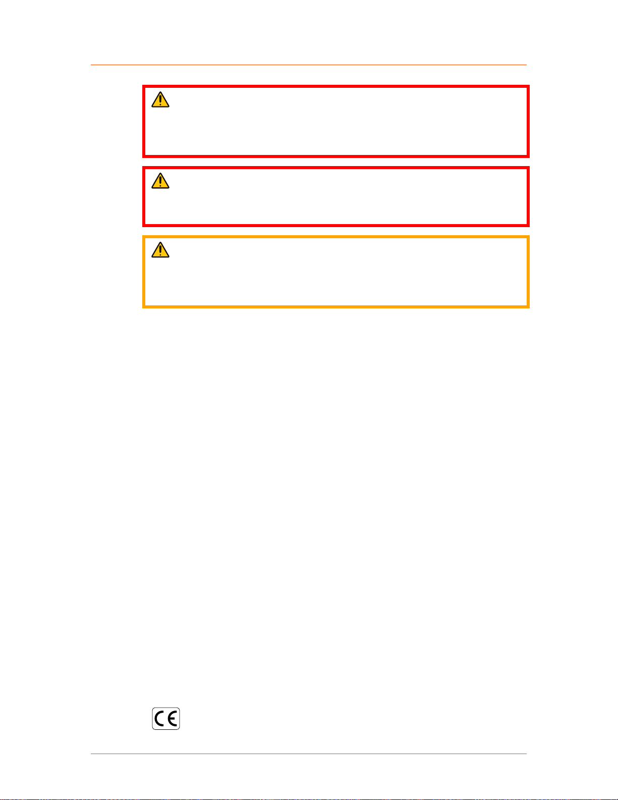
DANGER:
DANGER indicates an imminently hazardous situation that, if not avoided,
will result in death or serious injury. DANGER is limited to the most extreme
situations.
WARNING:
WARNING indicates a potentially hazardous situation that, if not avoided,
could result in death or serious injury, and/or property damage.
CAUTION:
CAUTION indicates a potentially hazardous situation that, if not avoided,
could result in minor or moderate injury, and/or property damage. CAUTION
is also used for property-damage-only accidents.
SAFETY GUIDELINES
Review the following information before attempting to install and operate the
product.
Rules for Safe Installation and Operation
Please note the following rules:
• Do not attempt to install or operate this equipment without proper training.
• Ensure that this unit is properly grounded.
• Ensure that all cables are properly connected.
• Verify that input voltage and current capacity are within specifications before
turning on the power supplies.
• Use proper electrostatic discharge (ESD) precautions.
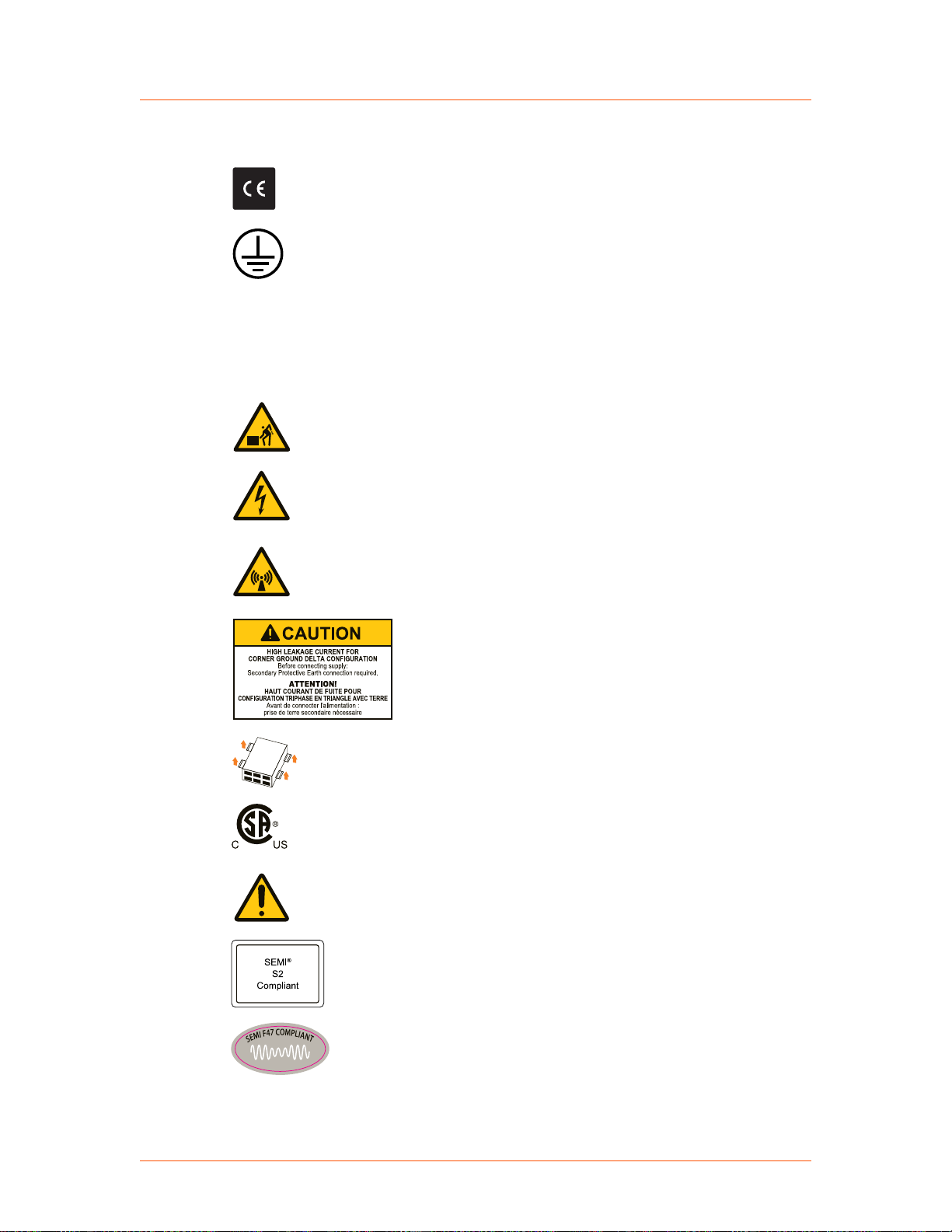
INTERPRETING PRODUCT LABELS
The following labels might appear on your unit:
CE label
57023942-00E Safety and Product Compliance Guidelines 1‑3
Advanced Energy
or
®
Paramount® Plus Generators
Complies with applicable European
directives.
Protective conductor terminal
This terminal must be connected first and
be of proper type and size for the circuit
with the highest voltage and current
carrying capacity. Note that other
connections might have higher
requirements than that of the mains
connection.
Heavy object—can cause muscle strain
or back injury
Hazardous voltage
Voltage > 30 V
, 42.4 V peak, or
RMS
60 VDC
Nonionizing radiation
Radio frequency emissions can be
harmful.
High leakage current
Four handle lift
Certified by CSA to North American
Safety Standards for both Canada and the
United States
Refer to manual for more information
SEMI® S2 compliant
SEMI F47 compliant
57023942-00E Safety and Product Compliance Guidelines 1‑4

Advanced Energy
®
PRODUCT COMPLIANCE
The following sections include information about unit compliance and certification,
including the conditions of use required to be in compliance with the standards and
directives.
Product Certification
Paramount® Plus Generators
Environmentally Friendly Use Period of
25 years per China RoHS—recycle
responsibly at end of life
European Union RoHS compliant
Certain options of this product may be certified according to the list below.
For more information, refer to the Certificate or Letter of Conformity (US) or
Declaration of Conformity (EU) accompanying the product.
• NRTL – Safety certified by CSA International, a Nationally Recognized Testing
Laboratory
• CE Marking – Self-declaration, assessed by AE Corporate Compliance
• EMC measurements – Verified by AE Corporate Compliance
• SEMI guidelines – Verified by AE Corporate Compliance
Safety and EMC Directives and Standards
For information concerning compliance to applicable EU requirements, refer to the
EU Declaration of Conformity for this unit. The Declaration of Conformity might
also include a supplementary section covering compliance to non-EU regulatory
requirements and/or industry standards or guidelines.
Conditions of Use
To comply with the stated directives and standards, you must meet the following
conditions of use:
• For corner-grounded delta configuration installation, excessive leakage occurs.
Secondary Protective Earth (ground) must be connected.
• Install and operate this unit in an overvoltage category according to
environmental specifications.
57023942-00E Safety and Product Compliance Guidelines 1‑5

Advanced Energy
• Install and operate this unit in a pollution degree environment according to
• Use only clean, well-conditioned water with low conductivity. See the cooling
• To prevent condensation, install and operate this device with an external water
• You must install and operate this device with a disconnect switch that conforms
• Use only a shielded cable for the input power connections.
• Use only an RF output power cable that meets all of the following
®
Paramount® Plus Generators
environmental specifications.
specifications.
solenoid valve so that water flow is interrupted when the device is not
operating.
to the applicable requirements. The switch must be easily accessible and near
the device.
requirements:
◦ Double shielded
◦ Inner and outer shield ≥ 90% coverage
◦ Inner or outer shield ≥ 95% coverage
• Use only a shielded cable for communications and/or control connections.
Environmental Compliance
• EU RoHS – European Union Directive 2011/65/EU (RoHS 2)
Restriction of the Use of Certain Hazardous Substances in Electrical and
Electronic Equipment
This product is EU RoHS 2 compliant, designed to contain no more than the
maximum concentration of hazardous substances listed in Annex II, with
possible exemptions from Annex III or IV. Because this product is installed as a
component in a large-scale fixed installation or stationary industrial tool: the
product is outside the scope of this Directive, compliance is not required, and
the EU RoHS Directive is not declared on the CE Declaration of Conformity.
• EU REACH – European Union Regulation (EC) No. 1907/2006
Registration, Evaluation, Authorization and Restriction of Chemicals
Advanced Energy manufactures articles subject to Article 33 of REACH and,
upon request, will provide information regarding Substances of Very High
Concern (SVHC) currently identified by the European Chemical Agency
(ECHA) that are contained in this product, at concentrations greater than 0.1%
by weight.
• China RoHS - People’s Republic of China (PRC) Ministry of Industry and
Information Technology (MIIT) Order #32 (China RoHS 2)
Management Methods for the Restriction of the Use of Hazardous Substances
Electrical and Electronic Products
57023942-00E Safety and Product Compliance Guidelines 1‑6

Advanced Energy
®
Paramount® Plus Generators
This product contains hazardous substances listed in PRC Standard GB/T
26572, above the maximum concentration limits stipulated. In compliance to
PRC Standard SJ/T 11364, AE provides a disclosure of hazardous substance
content and this product is marked with an Environmentally Friendly Use
Period (EFUP) of 25 years.
57023942-00E Safety and Product Compliance Guidelines 1‑7

Paramount
®
Plus Generators
Chapter
Product Overview
PLATFORM DESCRIPTION
The Advanced Energy Paramount RF generator provides radio frequency power into
a 50 Ω load by converting 3-phase, 47 Hz to 63 Hz AC mains line power into RF
energy at the generator specified frequency. High accuracy load or forward power
regulation, with internal protection limits, permit safe and reliable operation under all
load conditions. Cooling is achieved using both air and water.
A standard RS-232 serial control interface is provided for generator control using AE
Modbus commands. Additional interfaces such as analog, Ethernet, EtherCAT®,
DeviceNet®, and AE Navigator® II match control are also available.
The Paramount generator supports the following additional configurations or
features:
2
• Variable frequency
• Fixed frequency
• Frequency tuning
• Pulsing/pulse synchronization
• Multi-level pulsing
• Arc management
• Common exciter (CEX)
• Frequency band ranges from 2 MHz to 60 MHz
• Up to 15000 W maximum output power
• 200 VAC – 208 VAC, 208 VAC – 240 VAC, or 400 VAC – 480 VAC, 50 Hz –
60 Hz
THEORY OF OPERATION
Operation Overview
The fundamental purpose of the generator is to take three-phase, 47 Hz to 63 Hz AC
input at nominal voltages 200 VAC to 480 VAC (depending on the ordered
configuration) and convert it to RF energy at the specified frequency for the
57023942-00E Product Overview 2‑1

Advanced Energy
®
generator. The generator consists of four main systems: AC input, DC switching
mode power supply, RF, and logic/control.
AC Input
Line power is supplied to the generator through a unified assembly consisting of a
bulkhead connector, disconnect switch, and line filter. The disconnect switch
provides lockout/tagout capability.
☞ Important
The disconnect switch is not a circuit breaker.
Generator line protection is provided through an internal fuse assembly. These fuses
are sized according to the specified input operating line voltage and are installed at
the factory.
DC Switching Mode Power Supply
Line power is fed to the switching mode power supply (SMPS) where it is rectified
and boosted to a high voltage level. This high potential energy in turn feeds the
inverter and buck sections to supply controlled power to the RF section. The SMPS
also supplies auxiliary DC power to the logic/control modules. The DC SMPS
includes control logic for synchronization and regulation of the supply.
Paramount® Plus Generators
RF Section
The RF section takes a synthesized signal from the logic/control section into a series
of drivers. The drivers boost the RF to the proper level to drive the final amplifier
FETs. Power FET outputs are then combined to produce the final RF output for the
generator. An output sensor module, located just prior to the RF output connector,
provides feedback to the logic/control section.
Logic/Control Section
The logic/control module contains all microprocessor and logic circuits for the
overall control and operation of the generator. Interfaces to this assembly provide the
capability for RS-232 communication, user analog interface, and an Ethernet
interface. Optional interfaces include DeviceNet, PROFIBUS, and EtherCAT.
Additionally, expanded control options such as CEX and pulsing can be added. This
section of the generator manages all communications I/O and control loops.
57023942-00E Product Overview 2‑2

Paramount
®
Plus Generators
Chapter
Specifications
SPECIFICATIONS
The specifications vary by model. For model-specific information, see the product
specification for your unit. Your unit product specifications are included on the CD
that came with your unit. If you do not have access to the user manual CD, contact
AE Global Services.
Safety-related specifications are included in the printed Safety Information Guide
that shipped with your unit.
Related Links
• “AE Global Services” on page 6‑15
3
57023942-00E Specifications 3‑1

Paramount® Plus Generators
Chapter
Communication Controls
BASIC LED STATUS DISPLAY
The basic LED status display is on the rear panel of the product. This display
indicates the operating conditions described in the following table.
Table 4‑1. Status LEDs
LED Label Description
AC On This green LED is lit when the unit is receiving AC power.
RF On This green LED is lit when the unit has received an RF on command.
Depending on the selected setpoint value, RF power may or may not be
present at the output connector when this LED is lit.
This LED turns off when the unit receives an RF off command.
4
Interlock This green LED is lit when all of the following conditions are met:
• AC power is available in the unit
• The rectified voltage to the inverter section is within the allowable
voltage range
• All interlock criteria are satisfied
When this LED is lit, the unit is ready to supply output power.
Power Limit When not lit, this yellow LED indicates that the unit is able to satisfy the
requested setpoint power.
When lit, this LED indicates that the unit cannot satisfy the requested
setpoint due to a limit or alarm condition detected by the generator. Some
of the conditions that can cause an out-of-setpoint condition are high
VSWR, output voltage limits, and output current limits.
Overtemp When lit, this yellow LED indicates that the unit's internal temperature has
exceeded the allowable level.
• If RF is on when this error occurs, the error is latching, which means
that the temperature must fall below the limit and you must send the
unit an RF Off command to reset the unit.
• If RF is off when this error occurs, the error is self-clearing, which
means that, when the temperature falls back below the limit, the unit
will be ready to turn on.
Alarm When lit, this yellow LED indicates that the unit has a fault condition.
57023942-00E Communication Controls 4‑1
Pin 1Pin 13
Pin 25 Pin 14
Advanced Energy
®
Table 4‑1. Status LEDs (Continued)
LED Label Description
Fault conditions are either non-latching or latching:
• If the fault is non-latching and RF is off, the fault LED will turn off
when the condition that caused the fault is corrected.
• If the fault is a latching fault or if the fault occurred when RF was on,
the fault LED will only turn off if the fault is no longer active and the
latched condition has been cleared by issuing an RF off command to
the unit.
25-PIN USER PORT
The Paramount platform offers several User ports. This section applies to Paramount
units that have 25-pin User ports.
Paramount® Plus Generators
25-Pin User Port Connector
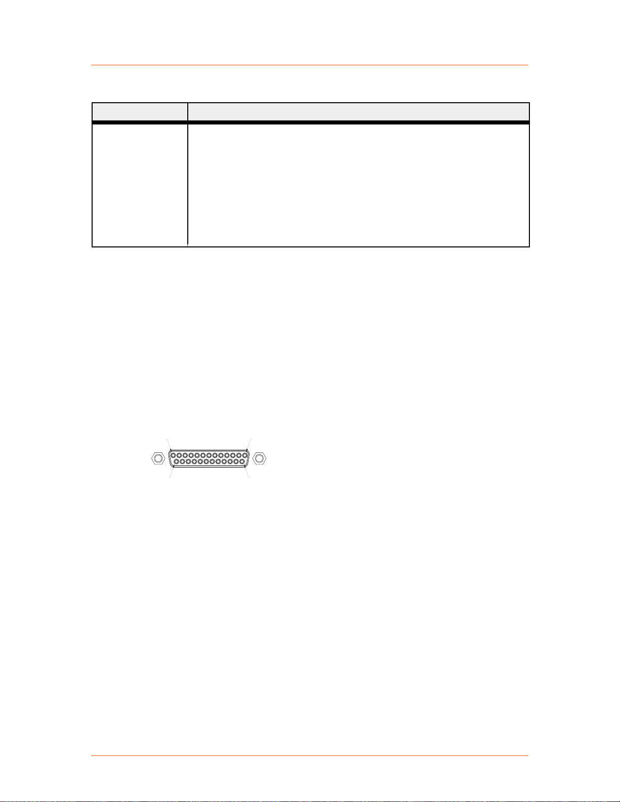
The User port uses a 25-pin, shielded, female, subminiature-D connector.
Figure 4‑1. User port connector, 25 pin
Unless otherwise specified, all analog signals are 0 V to 10 V while all digital signals
are 4 V to 24 V, opto-coupled (open-collector signals with return lines nonreferenced
to ground).
Ground/Return lines are floating and need to be connected as close to the system
ground as possible.
Satisfying Minimal Requirements for the 25-Pin User Port
The interlock must be satisfied regardless of the control mode. When in host control
mode, it is not required to assert the RF PWR ON CONTROL input on the user
interface.
57023942-00E Communication Controls 4‑2
Advanced Energy
☞ Important
If you are not using the User port to control or monitor the unit, you can use a
“dummy” or “cheater” plug to satisfy these signals, thereby ignoring the User port.
To make a dummy plug, solder jumpers on a mating connector.
®
Paramount® Plus Generators
If you are controlling your generator through a port other than the User port,
make sure that the control mode is set appropriately (to host mode to control
through the host port, for example). The control mode can be set through an
AE host command.
Table 4‑2. Jumpers on a dummy plug to satisfy minimal signal requirements
Jumper Between Pins Description
10 and 23 Satisfies INTERLOCK LOOP signal
If desired, you can tie your system interlocks in series with the generator
INTERLOCK LOOP signal.
25-Pin User Port Cabling Requirements
The cable used to connect the generator’s User port to the system controller must be
a shielded, 25-wire I/O cable. Twisted-pair wiring may be used but is not mandatory.
Signal losses should be minimized by keeping the cable length as short as possible.
The maximum recommended cable length between the generator and the controller is
10 meters (33′). To minimize interference from adjacent electrical equipment, the
EMI shield in the cable must be terminated to the metal shells of the cable’s
connectors. Additionally, the chassis of the generator must be tied to a local earth
ground through an adequately sized copper grounding strap.
Apex Compatible 25-Pin User Port
Your Paramount generator has an Apex compatible 25-pin User port.
PIN DESCRIPTIONS FOR APEX COMPATIBLE USER PORT
Table 4‑3. 25-pin Apex User port pin descriptions
Signal
Pin
1 14 SETPOINT
2 15 RFL PWR
57023942-00E Communication Controls 4‑3
Related
Pin
Name Signal
STATUS
RETURN
MONITOR
Type
Digital
output
Analog
output
Description
See pin 14.
This signal provides a linearly scaled
read back of reflected power.

Advanced Energy
®
Table 4‑3. 25-pin Apex User port pin descriptions (Continued)
Signal
Pin
Related
Pin
Name Signal
Type
0 V to 10 V = 0 to maximum rated
power output.
Pin 15 must be grounded.
Paramount® Plus Generators
Description
3 16 FWD/LOAD
PWR MONITOR
4 17 RF PWR ON Digital
Analog
output
input
This signal provides a linearly scaled
read back of forward power when the
generator is operated in forward power
regulation mode or the load power when
operated in the load power regulation
mode.
0 V to 10 V = 0 to maximum rated
power output.
Pin 16 must be grounded.
• In analog control mode, applying a
positive voltage from 4 VDC to 24
VDC enables RF output. When
voltage is less than 1 VDC, RF
output is disabled.
• In Host control mode, this input is
ignored.
☞ Important
The interlocks must be satisfied
and the setpoint must be within
the output power range before
unit will deliver power.
5 18 SETPOINT Analog
input
This pin linearly controls the RF output
of the generator.
0 V to 10 V = 0 to maximum rated
power output.
☞ Important
Setpoint must be greater than the
low power limit before the unit
will deliver power.
6 19 DC BIAS/
POWER
REGULATION
57023942-00E Communication Controls 4‑4
Digital
input
This pin is used in conjunction with pin
7 to allow the generator to regulate its
power based on an external feedback
signal.
Applying a positive voltage from 4 VDC
to 24 VDC to this pin (reference to
ground pin 19) causes the generator to
regulate on the input voltage signal on

Advanced Energy
®
Table 4‑3. 25-pin Apex User port pin descriptions (Continued)
Signal
Pin
Related
Pin
Name Signal
Type
pin 7 (DC BIAS INPUT). When voltage
is less than 1 VDC, or if there is no
connection to this pin, the generator
regulates power.
Paramount® Plus Generators
Description
7 20 DC BIAS INPUT Analog
input
8 21 FWD/LOAD
PWR
Digital
input
REGULATION
9 22 OVERTEMP
RETURN
Digital
output
This pin is used in conjunction with the
signal on pin 6 to allow the generator to
regulate its power based on an external
feedback signal.
This user-defined 0 V to 10 V signal
provides an input which you can use for
closing the power control loop around
external components in the RF path.
The unit usually uses Pin 7 for bias
regulation with this input signal being a
scaled representation of the DC bias
measured at a match network.
Applying a positive voltage between
4 VDC and 24 VDC to this pin causes
the generator to regulate on load power.
When voltage is less than 1 VDC, or if
there is no connection to this pin, the
generator defaults to forward power
regulation.
See pin 22.
10 23 INTERLOCK
LOOP
External voltage interlock loop, internal
voltage supplied. This pin, when
connected externally to pin 23, closes the
interlock and allows the RF output to be
enabled.
The external circuit should be capable of
switching 100 mA at 24 VDC.
11 24 DC BUS OK
RETURN
12 25 CEX LOCK Digital
Digital
output
output
See pin 24.
When the generator is successfully
phase-locked to an external oscillator, a
low (opto-coupler output) impedance is
created between this pin and return pin
25 (6 mA maximum).
13 21 +15 VDC This pin, referenced to ground, provides
a +15 VDC ± 1 V auxiliary supply for
external use. 100 mA maximum.
57023942-00E Communication Controls 4‑5

Advanced Energy
®
Table 4‑3. 25-pin Apex User port pin descriptions (Continued)
Signal
Pin
Related
Pin
Name Signal
Type
Paramount® Plus Generators
Description
14 1 SETPOINT
STATUS
15 2 RFL POWER
MONITOR
Digital
output
Analog
output
RETURN
16 3 FWD/LOAD
PWR MONITOR
Analog
output
RETURN
17 4 RF PWR ON
RETURN
18 5 SETPOINT
RETURN
Digital
input
Analog
input
19 DC GROUND Analog
output
20 7 DC BIAS INPUT
RETURN
21 CHASSIS
GROUND
Analog
input
Chassis
ground
When the generator is out of setpoint, a
low (opto-coupler output) impedance is
created between this pin and pin 1 (6 mA
maximum).
See pin 2.
See pin 3.
See pin 4.
See pin 5.
This pin represents DC ground
connection common to chassis ground.
See pin 7.
Chassis ground connection common to
DC ground.
22 9 OVERTEMP Digital
output
23 10 INTERLOCK
LOOP RETURN
24 11 DC BUS OK Digital
output
25 12 CEX LOCK
RETURN
Digital
output
When an internal overtemperature
shutdown condition is detected, a low
(opto-coupler output) impedance is
created between this pin and pin 9 (6 mA
maximum).
See pin 10.
When the interlocks are satisfied, AC
input voltage is within specification, and
no generator faults exist, a low (optocoupler output) impedance is created
between this pin and pin 11 (6 mA
maximum).
See pin 12.
57023942-00E Communication Controls 4‑6
User
Unit
Voltage Measurement Device
(see pin description
for scaling)
Pin 15 must
be grounded
User
Unit
Voltage Measurement Device
(see pin description
for scaling)
Pin 16 must
be grounded
Advanced Energy
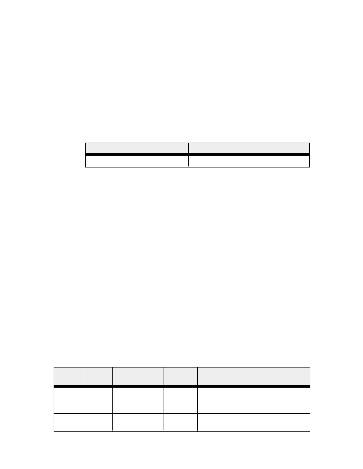
WIRING DIAGRAMS FOR APEX COMPATIBLE USER PORT
Figure 4‑2. REFL PWR MONITOR (pins 2 and 15)
®
Paramount® Plus Generators
57023942-00E Communication Controls 4‑7
Figure 4‑3. FWD/LOAD PWR MONITOR (pins 3 and 16)
User Unit
+4 V to +24 V
User Unit
See pin description
for scaling
User Unit
+4 V to +24 V
Advanced Energy
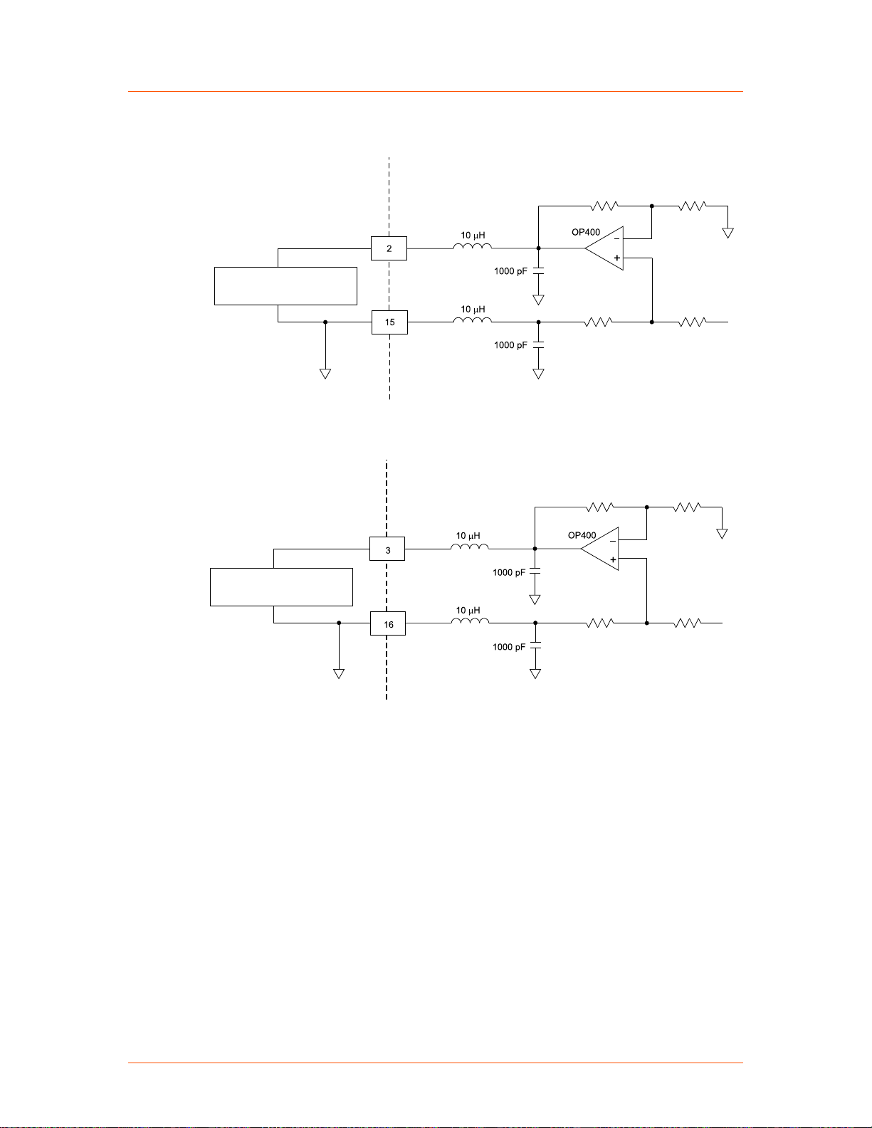
Figure 4‑4. RF PWR ON (pins 4 and 17)
®
Paramount® Plus Generators
Figure 4‑5. SETPOINT (pins 5 and 18)
Figure 4‑6. DC BIAS/POWER REGULATION (pins 6 and 19)
57023942-00E Communication Controls 4‑8
 Loading...