


 Loading...
Cesar® Generator
Air-Cooled
User Manual
January 2013 57023916-00B

Cesar® Generator
Air-Cooled
User Manual
January 2013 57023916-00B

Advanced Energy
COPYRIGHT
This manual and the information contained herein are the proprietary property of Advanced Energy Industries, Inc.
No part of this manual may be reproduced or copied without the express written permission of Advanced Energy Industries, Inc. Any unauthorized use of this manual or its contents is strictly prohibited. Copyright © 2011-2013 Advanced Energy Industries, Inc. All Rights Reserved.
DISCLAIMER AND LIMITATION OF LIABILITY
The information contained in this manual is subject to change by Advanced Energy Industries, Inc. without prior notice. Advanced Energy Industries, Inc. makes no warranty of any kind whatsoever, either expressed or implied, with respect to the information contained herein. Advanced Energy Industries, Inc. shall not be liable in damages, of whatever kind, as a result of the reliance on or use of the information contained herein.
PRODUCT USAGE STATEMENT
 WARNING :
Read this entire manual and all other publications pertaining to the work to be performed before you install, operate, or maintain this equipment. Practice all plant and product safety instructions and precautions. Failure to follow instructions can cause personal injury and/or property damage. If the equipment is used in a manner not specified by the manufacturer, the protection provided by the equipment may be impaired. All personnel who work with or who are exposed to this equipment must take precautions to protect themselves against serious or possibly fatal bodily injury.
Advanced Energy Industries, Inc., (AE) provides information on its products and associated hazards, but it assumes no responsibility for the after-sale operation of the equipment or the safety practices of the owner or user.
NEVER DEFEAT INTERLOCKS OR GROUNDS.
TRADEMARKS
 is a registered trademark of Advanced Energy Industries, Inc.
Cesar® is a registered trademark of Advanced Energy Industries, Inc.
iv |
57023916-00B |

Cesar® Generator
Dressler® is a registered trademark of Advanced Energy Industries, Inc.
Epic® is a registered trademark of the Lapp Group.
HPG™ is a trademark of Advanced Energy Industries, Inc.
Modbus® is a registered trademark of Gould, Inc.
Navigator® is a registered trademark of Advanced Energy Industries, Inc.
Navio™ is a trademark of Advanced Energy Industries, Inc.
Neutrik® is a registered trademark of Neutrik Aktiengesellschaft.
Rectus® is a registered trademark of RECTUS, GmbH.
SERTO® is a registered trademark of SERTO Ltd.
Siemens® is a registered trademark of Siemens AG.
VarioMatch™ is a trademark of Advanced Energy Industries, Inc.
Windows® is a registered trademark of the Microsoft Corporation.
Windows NT® is a registered trademark of the Microsoft Corporation.
CUSTOMER FEEDBACK
Advanced Energy’s technical writing staff has carefully developed this manual using research-based document design principles. However, improvement is ongoing, and the writing staff welcomes and appreciates customer feedback. Please send any comments on the content, organization, or format of this user manual to:
• tech.writing@aei.com
To order a manual, please contact Technical Support:
• technical.support@aei.com
57023916-00B |
v |

Advanced Energy
vi |
57023916-00B |

Cesar® Generator
Table of Contents
Chapter 1. Safety and Product Compliance Guidelines
|
|
Products Documented in this Manual ................................................................... |
1-1 |
Important Safety Information ................................................................................. |
1-1 |
Danger, Warning, and Caution Boxes in the Manual ............................................ |
1-1 |
Safety Guidelines .................................................................................................. |
1-2 |
Rules for Safe Installation and Operation ....................................................... |
1-2 |
Interpreting Product Labels ................................................................................... |
1-2 |
Product Compliance .............................................................................................. |
1-3 |
Product Certification ....................................................................................... |
1-3 |
Safety and EMC Directives and Standards .................................................... |
1-4 |
Electromagnetic Compatibility (EMC) Directives and Standards ............. |
1-4 |
Safety Directives and Standards .............................................................. |
1-4 |
Conditions of Use ........................................................................................... |
1-5 |
Interlocks and Limiting Conditions ........................................................................ |
1-6 |
|
|
Chapter 2. Product Overview |
|
|
|
General Description .............................................................................................. |
2-1 |
Theory of Operation .............................................................................................. |
2-2 |
|
|
Chapter 3. Specifications |
|
|
|
Physical Specifications .......................................................................................... |
3-1 |
Electrical Specifications ........................................................................................ |
3-2 |
Cooling Specifications ........................................................................................... |
3-4 |
Environmental Specifications ................................................................................ |
3-4 |
|
|
Chapter 4. Communication Controls |
|
|
|
Diagnostic Interface .............................................................................................. |
4-1 |
Matching Interface ................................................................................................. |
4-1 |
Matching Interface Connector ........................................................................ |
4-1 |
Matching Interface Pin Descriptions ............................................................... |
4-1 |
User Port ............................................................................................................... |
4-3 |
25-Pin User Port ............................................................................................. |
4-4 |
User Port Connector ................................................................................ |
4-4 |
Satisfying Minimal Requirements for the 25-pin User Port ...................... |
4-4 |
25-pin User Port Cabling Requirements .................................................. |
4-5 |
Activating the 25-Pin User Port ................................................................ |
4-5 |
Resolving Error Displays When Using the 25-Pin User Port ................... |
4-6 |
57023916-00B |
Table of Contents |
vii |

Advanced Energy
25-pin User Port Pin Descriptions and Wiring Diagrams ......................... |
4-6 |
15-Pin User Port ........................................................................................... |
4-18 |
User Port Connector .............................................................................. |
4-18 |
Satisfying Minimal Requirements for the 15-pin User Port .................... |
4-18 |
15-pin User Port Cabling Requirements ................................................ |
4-20 |
Activating the 15-Pin User Port .............................................................. |
4-20 |
Resolving Error Displays When Using the 15-Pin User Port ................. |
4-21 |
15-pin User Port Pin Descriptions and Wiring Diagrams ....................... |
4-21 |
Cesar Generator Host Port ................................................................................. |
4-31 |
RS-232 Interface .......................................................................................... |
4-31 |
RS-232 Connector ................................................................................. |
4-32 |
RS-232 Port Pin Descriptions ................................................................ |
4-32 |
AE Bus Transmission Parameters ......................................................... |
4-32 |
AE Bus Protocol ..................................................................................... |
4-33 |
Creating an Ideal Communications Transaction .................................... |
4-35 |
PROFIBUS Interface .................................................................................... |
4-37 |
PROFIBUS Connector ........................................................................... |
4-38 |
PROFIBUS Port Pin and Signal Descriptions ........................................ |
4-38 |
PROFIBUS Cabling and Termination .................................................... |
4-38 |
AE PROFIBUS Protocol ......................................................................... |
4-39 |
PROFIBUS Command Structure ........................................................... |
4-42 |
Ethernet Interface ......................................................................................... |
4-44 |
Ethernet Connector and Indicators ........................................................ |
4-44 |
Understanding AE TCP Commands and Register Types (FC23) .......... |
4-45 |
Using Modbus/TCP FC23 ...................................................................... |
4-46 |
AE Bus Commands ...................................................................................... |
4-50 |
Activating Host Port Remote Control (AE Bus Command 14) ............... |
4-51 |
AE Bus Command Status Response (CSR) Codes ............................... |
4-53 |
AE Bus Port Command Set ................................................................... |
4-54 |
|
|
Chapter 5. Installation, Setup, and Operation |
|
|
|
Preparing to Install the Unit ................................................................................... |
5-1 |
Spacing Requirements ................................................................................... |
5-1 |
Dimensional Drawings .................................................................................... |
5-1 |
Installation Requirements ............................................................................... |
5-3 |
Tools Required for Installation ........................................................................ |
5-3 |
Unpacking the Unit ......................................................................................... |
5-4 |
Lifting the Unit .......................................................................................... |
5-4 |
Installing the Unit ................................................................................................... |
5-5 |
Mounting ......................................................................................................... |
5-5 |
Grounding ....................................................................................................... |
5-5 |
Connecting Output Power .............................................................................. |
5-6 |
To Connect Output Power ....................................................................... |
5-6 |
Connecting Communication Interfaces ........................................................... |
5-8 |
To Connect the Communication Interfaces .............................................. |
5-8 |
Connecting the Generator to a System Interlock Loop ................................... |
5-9 |
Satisfying the Interlock With a 25-pin User Port ...................................... |
5-9 |
Satisfying the Interlock With a 15-pin User Port ...................................... |
5-9 |
viii |
Table of Contents |
57023916-00B |

Cesar® Generator
Connecting a VarioMatch or Navio Match Network (Optional) ....................... |
5-9 |
Connecting Common Exciter (CEX) Circuitry (Optional) .............................. |
5-10 |
To Make the CEX Connections .............................................................. |
5-10 |
Connecting AC Input (Mains) Power ............................................................ |
5-11 |
Connecting and Setting Ethernet (Modbus/TCP) Communication ............... |
5-12 |
To Connect for Ethernet Communication ............................................... |
5-12 |
Setting the IP Configuration for Ethernet Communication ..................... |
5-12 |
First Time Operation ........................................................................................... |
5-13 |
Operating the Cesar Generator for the First Time With the User Port ......... |
5-14 |
To Operate the Cesar Generator for the First Time With the 25-pin |
|
User Port .............................................................................................. |
5-14 |
To Operate the Cesar Generator for the First Time With the 15-pin |
|
User Port .............................................................................................. |
5-15 |
Operating the Cesar Generator for the First Time With the Host Port .......... |
5-16 |
Operating the Cesar Generator for the First Time With the Front Panel ...... |
5-17 |
Cesar Generator Front Panel .............................................................................. |
5-18 |
Front Panel Control Elements ...................................................................... |
5-19 |
Using the Front Panel Program Menu .......................................................... |
5-20 |
Accessing the Program Menu ................................................................ |
5-20 |
Entering Values in the Program Menu ................................................... |
5-21 |
Front Panel Program Menu Tree ........................................................... |
5-22 |
Viewing Measurements in the Display .......................................................... |
5-23 |
Remote Control Operation .................................................................................. |
5-24 |
Viewing and Using the Front Panel when in Remote Control Mode ............. |
5-24 |
RF Control and Resetting Errors .................................................................. |
5-25 |
Normal Operation ................................................................................................ |
5-26 |
Setting Regulation Mode .............................................................................. |
5-26 |
Determining the Regulation Mode Setting ............................................. |
5-27 |
To Set Regulation Mode ........................................................................ |
5-28 |
Setting the Pulse Function ............................................................................ |
5-29 |
Selecting Internal or External Pulsing .................................................... |
5-29 |
Changing the Pulse Input Configuration Settings .................................. |
5-30 |
To Turn Off Pulsing ................................................................................ |
5-31 |
Creating Recipes (RF on/off, Slew Rate, Power Ramping) .......................... |
5-31 |
Creating an RF On/Off Ramp Recipe .................................................... |
5-32 |
Creating a Slew Rate Recipe ................................................................. |
5-32 |
Creating a Power Ramp Recipe ............................................................ |
5-33 |
To Turn Off the Recipe Settings Feature ............................................... |
5-34 |
Recipe Settings Operating Screen ......................................................... |
5-34 |
Setting and Disabling Remote Control Override ........................................... |
5-35 |
Selecting Remote Control Override ....................................................... |
5-35 |
Disabling Remote Control Override ....................................................... |
5-36 |
Setting and Turning Off the Target Lifetime Feature .................................... |
5-37 |
Setting Target Lifetime Parameters ....................................................... |
5-37 |
To Turn Off the Target Lifetime Feature ................................................ |
5-37 |
Resetting a Target Lifetime .................................................................... |
5-38 |
Changing Reflected Power Settings ............................................................. |
5-38 |
Changing the Device Configuration Settings ................................................ |
5-39 |
To Change the Default Device Configuration Settings .......................... |
5-40 |
Setting and Using Preset Generator Settings for Different Applications . ..... |
5-41 |
57023916-00B |
Table of Contents |
ix |

Advanced Energy
To Store a Preset ................................................................................... |
5-41 |
To Erase a Preset .................................................................................. |
5-42 |
To Use a Preset ..................................................................................... |
5-42 |
Controlling a VarioMatch or Navio Match Network Attached to the |
|
Generator .......................................................................................................... |
5-42 |
Determining the Current Match Network Tune Setting ................................. |
5-43 |
Setting Tune Control ..................................................................................... |
5-43 |
Determining Automatic Tuning Presets ........................................................ |
5-45 |
Adjusting the Capacitors When in Manual Tune .......................................... |
5-45 |
Using the Cable Attenuation Feature .................................................................. |
5-47 |
Cable Attenuation Description ...................................................................... |
5-47 |
Forward Power Calculation .................................................................... |
5-48 |
Reflected Power Calculation .................................................................. |
5-48 |
Cable Attenuation and Reflected Power Settings ......................................... |
5-49 |
Connecting to an Ethernet-Enabled Unit With a Web Browser ........................... |
5-49 |
|
|
Chapter 6. Troubleshooting and Global Services |
|
|
|
Before Contacting AE Global Services ................................................................. |
6-1 |
Checks With Power Off .................................................................................. |
6-1 |
Checks With Power On .................................................................................. |
6-2 |
Troubleshooting Checklists ............................................................................ |
6-2 |
General Troubleshooting ......................................................................... |
6-2 |
Matching Network Troubleshooting ......................................................... |
6-3 |
Interlock Not Satisfied ..................................................................................... |
6-3 |
Front Panel Display (LCD) Not Lit .................................................................. |
6-4 |
Fuse is Blown ................................................................................................. |
6-4 |
Communication Problems .............................................................................. |
6-4 |
Capacitor Failure ............................................................................................ |
6-5 |
Incorrect Input Voltage ................................................................................... |
6-5 |
Improper Impedance Range ........................................................................... |
6-5 |
Improper RF Connection or Cabling ............................................................... |
6-6 |
Improper Grounding ....................................................................................... |
6-6 |
Improper Matching Interface Connection ....................................................... |
6-6 |
Improper Tuning Adjustment .......................................................................... |
6-7 |
Troubleshooting Using Error Codes ...................................................................... |
6-7 |
Fault and Warning Types and Clearing Faults ............................................... |
6-7 |
Error Code Descriptions and Resolutions ...................................................... |
6-8 |
Warning Message Descriptions and Resolutions ......................................... |
6-10 |
Communication Warning Descriptions and Resolutions ............................... |
6-12 |
AE Global Services ............................................................................................. |
6-14 |
Returning Units for Repair ................................................................................... |
6-15 |
Decommissioning the Unit .................................................................................. |
6-15 |
x |
Table of Contents |
57023916-00B |
Cesar® Generator
List of Tables
Table 1-1. Cesar limiting conditions ...................................................................... |
1-7 |
Table 3-1. Physical specifications ......................................................................... |
3-1 |
Table 3-2. Electrical specifications ........................................................................ |
3-2 |
Table 3-3. Air cooling specifications ...................................................................... |
3-4 |
Table 3-4. Environmental standard specifications ............................................... |
3-4 |
Table 3-5. Climatic specifications .......................................................................... |
3-4 |
Table 4-1. Matching interface pin descriptions ...................................................... |
4-1 |
Table 4-2. User Port Signal Specifications ............................................................ |
4-7 |
Table 4-3. 25-Pin User Port Pin Descriptions ...................................................... |
4-8 |
Table 4-4. 15-Pin User Port Pin Descriptions .................................................... |
4-21 |
Table 4-5. Setting regulation mode with 15-pin User Port pins 1 and 2 .............. |
4-24 |
Table 4-6. RS-232 port pin descriptions .............................................................. |
4-32 |
Table 4-7. AE Bus byte structure ........................................................................ |
4-35 |
Table 4-8. PROFIBUS port pin and signal descriptions ...................................... |
4-38 |
Table 4-9. Baud rate and cable lengths .............................................................. |
4-38 |
Table 4-10. PROFIBUS status LEDs .................................................................. |
4-40 |
Table 4-11. Configuration of PROFIBUS download packet bytes ....................... |
4-42 |
Table 4-12. PROFIBUS upload packet status bit flags ...................................... |
4-43 |
Table 4-13. Packet format for FC23 send ........................................................... |
4-46 |
Table 4-14. Packet format for FC23 response .................................................... |
4-47 |
Table 4-15. Packet format for FC23 exception error ........................................... |
4-48 |
Table 4-16. Packet format for command 168 send ............................................. |
4-49 |
Table 4-17. Packet format for command 168 response ...................................... |
4-50 |
Table 4-18. AE Bus command 14 remote control settings, resets, and |
|
overrides ............................................................................................................ |
4-52 |
Table 4-19. AE Bus command status response (CSR) codes ............................ |
4-53 |
Table 4-20. AE Bus Commands .......................................................................... |
4-54 |
Table 4-21. Remote control override settings (command 29) ............................. |
4-81 |
Table 5-1. Input connector pin description ......................................................... |
5-11 |
Table 5-2. Remote control mode displayed on the front panel ........................... |
5-25 |
Table 5-3. RF on/off control ................................................................................ |
5-26 |
Table 5-4. Adjusting VarioMatch match network capacitors .............................. |
5-46 |
Table 6-1. Error codes .......................................................................................... |
6-8 |
Table 6-2. Warning messages ............................................................................ |
6-11 |
Table 6-3. Communication warning messages ................................................... |
6-12 |
Table 6-4. AE Global Services 24 X 7 contact information ................................. |
6-15 |
57023916-00B |
List of Tables |
xi |

Advanced Energy
xii |
List of Tables |
57023916-00B |

Cesar® Generator
List of Figures
Figure 2-1. Cesar block diagram ........................................................................... |
2-2 |
Figure 4-1. Matching interface connector .............................................................. |
4-1 |
Figure 4-2. User Port connector, 25 Pin ................................................................ |
4-4 |
Figure 4-3. Reflected power monitor (pins 2 and 15) .......................................... |
4-13 |
Figure 4-4. Forward/Load power monitor (pins 3 and 16) ................................... |
4-13 |
Figure 4-5. RF POWER ON signal wiring (pins 4 and 17) .................................. |
4-13 |
Figure 4-6. SET POINT signal wiring (pins 5 and 18) ......................................... |
4-14 |
Figure 4-7. RF FORWARD POWER/DC BIAS REGULATION wiring (pins 6 |
|
and 19) .............................................................................................................. |
4-14 |
Figure 4-8. DC BIAS MONITOR signal wiring (pins 7 and 20) (units with DC |
|
Bias In) .............................................................................................................. |
4-14 |
Figure 4-9. DC BIAS MONITOR signal wiring (pins 7 and 20) (units with DC |
|
Bias Out) ............................................................................................................ |
4-15 |
Figure 4-10. RF FORWARD/LOAD REGULATION signal wiring (pins 8 and |
|
21) ..................................................................................................................... |
4-15 |
Figure 4-11. INTERLOCK LOOP signal wiring (pins 10 and 23) ........................ |
4-16 |
Figure 4-12. +15 VOLT DC signal wiring (pins 13 and 21) ................................. |
4-16 |
Figure 4-13. SET POINT STATUS signal wiring (pins 14 and 1) ........................ |
4-17 |
Figure 4-14. OVERTEMPERATURE signal wiring (pins 22 and 9) ..................... |
4-17 |
Figure 4-15. INTERLOCK SATISFIED signal wiring (pins 24 and 11) ................ |
4-17 |
Figure 4-16. BLANKING/PULSING signal wiring (pins 25 and 19) ..................... |
4-18 |
Figure 4-17. User Port connector, 15 Pin ............................................................ |
4-18 |
Figure 4-18. Interlock interface connector ........................................................... |
4-19 |
Figure 4-19. OPERATING MODE A wiring diagram (pins 1 and 8) .................... |
4-25 |
Figure 4-20. OPEATING MODE B wiring diagram (pins 2 and 8) ....................... |
4-25 |
Figure 4-21. READY STATUS wiring diagram (pins 3 and 8) ............................. |
4-26 |
Figure 4-22. ERROR wiring diagram (pins 4 and 8) ........................................... |
4-26 |
Figure 4-23. MAXIMUM POWER LEVEL REACHED wiring diagram (pins 5 |
|
and 8) ................................................................................................................ |
4-27 |
Figure 4-24. RF ON wiring diagram (pins 6 and 8) ............................................. |
4-27 |
Figure 4-25. INTERFACE VOLTAGE wiring diagram (pins 7 and 8) .................. |
4-28 |
Figure 4-26. BLANKING/PULSING MODE wiring diagram (pins 9 and 8) .......... |
4-28 |
Figure 4-27. RF POWER ON wiring diagram (pins 10 and 8) ............................. |
4-29 |
Figure 4-28. DC BIAS SET POINT wiring diagram (pins 11 and 8) .................... |
4-29 |
Figure 4-29. RF POWER SET POINT wiring diagram (pins 12 and 8) ............... |
4-29 |
Figure 4-30. TEST VOLTAGE FOWARD POWER wiring diagram (pins 13 |
|
and 8) ................................................................................................................ |
4-30 |
Figure 4-31. TEST VOLTAGE REFLECTED POWER wiring diagram (pins |
|
14 and 8) ........................................................................................................... |
4-30 |
Figure 4-32. TEST VOLTAGE FOR DC BIAS wiring diagram (pins 15 and |
|
8) ....................................................................................................................... |
4-31 |
Figure 4-33. RS-232 port connector .................................................................... |
4-32 |
Figure 4-34. Graphic representation of a message packet ................................. |
4-34 |
Figure 4-35. AE Bus communications transaction .............................................. |
4-36 |
Figure 4-36. Communications transaction example ............................................ |
4-37 |
57023916-00B |
List of Figures |
xiii |

Advanced Energy
Figure 4-37. PROFIBUS port connector ............................................................. |
4-38 |
||
Figure 4-38. Example of a segment .................................................................... |
4-39 |
||
Figure 4-39. Ethernet connector and indicators .................................................. |
4-45 |
||
Figure 5-1. Cesar unit dimensions ........................................................................ |
5-2 |
||
Figure 5-2. Cesar rear view ................................................................................... |
5-3 |
||
Figure 5-3. RF Output connector .......................................................................... |
5-6 |
||
Figure 5-4. RF cover ............................................................................................. |
5-6 |
||
Figure 5-5. RF / User Port interlock adapter cable ................................................ |
5-7 |
||
Figure 5-6. RF / User Port interlock adapter cable, attached to unit ..................... |
5-8 |
||
Figure 5-7. |
CEX Connector ................................................................................. |
5-10 |
|
Figure 5-8. |
AC Input (Mains) connector .............................................................. |
5-11 |
|
Figure 5-9. |
Front panel ........................................................................................ |
5-19 |
|
Figure 5-10. |
Front panel program menu tree ...................................................... |
5-22 |
|
Figure 5-11. |
Front panel program menu tree (continued) ................................... |
5-23 |
|
Figure 5-12. |
Generator with no cable attenuation ............................................... |
5-48 |
|
Figure 5-13. |
Generator with cable attenuation .................................................... |
5-48 |
|
Figure 6-1. |
Input (Mains) connector and fuse box ................................................ |
6-4 |
|
xiv |
List of Figures |
57023916-00B |
Cesar® Generator |
|
Chapter |
|
|
1 |
|
|
Safety and Product Compliance
Guidelines
PRODUCTS DOCUMENTED IN THIS MANUAL
This user manual documents air-cooled Cesar generators.
The following part numbers include some non-standard features, which will be called out where they apply:
•61300129: DC Bias Out on the User Port. All other part numbers: DC Bias In on the User Port.
•61300121: 0 V to 5 V scaling on the User Port. All other part numbers: 0 V to 10 V scaling on the User Port.
IMPORTANT SAFETY INFORMATION
To ensure safe installation and operation of the Advanced Energy Cesar unit, read and understand this manual before attempting to install and operate this unit. At a minimum, read and follow the safety guidelines, instructions, and practices.
DANGER, WARNING, AND CAUTION BOXES IN THE MANUAL
This symbol represents important notes concerning potential harm to people, this unit, or associated equipment. Advanced Energy includes this symbol in Danger, Warning, and Caution boxes to identify specific levels of hazard seriousness.
1027
 DANGER:
DANGER indicates an imminently hazardous situation that, if not avoided, will result in death or serious injury. DANGER is limited to the most extreme
situations.
57023916-00B |
Safety and Product Compliance Guidelines |
1 1 |
Advanced Energy
 WARNING:
WARNING indicates a potentially hazardous situation that, if not avoided,
could result in death or serious injury, and/or property damage.
 CAUTION:
CAUTION indicates a potentially hazardous situation that, if not avoided, could result in minor or moderate injury, and/or property damage. CAUTION
is also used for property-damage-only accidents.
SAFETY GUIDELINES
Review the following information before attempting to install and operate the product.
Rules for Safe Installation and Operation
Please note the following rules:
•Do not attempt to install or operate this equipment without proper training.
•There are no user-serviceable parts inside the unit. Refer servicing to trained service personnel.
•Ensure that this unit is properly grounded.
•Ensure that all cables are properly connected.
•Verify that input line voltage and current capacity are within specifications before turning on the power supplies.
•Use proper electrostatic discharge (ESD) precautions.
•Always be careful around this equipment.
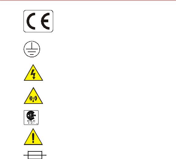
INTERPRETING PRODUCT LABELS
The following labels may appear on your unit:
1 2 |
Safety and Product Compliance Guidelines |
57023916-00B |
Cesar® Generator
CE label
1020
Protective Earth ground
1029
Hazardous voltage
1028
Nonionizing radiation
1030
NRTL: Nationally Recognized Testing
Laboratory
Refer to manual for more information
1027
Electrical fuse
PRODUCT COMPLIANCE
The following sections include information about unit compliance and certification, including the conditions of use required to be in compliance with the standards and directives.
Product Certification
Certain options of this product may be certified according to the list below.
For more information, refer to the Certificate or Letter of Conformity (US) or Declaration of Conformity (EU) accompanying the product.
•NRTL – Safety certified by CSA International, a Nationally Recognized Testing Laboratory
•CE Marking – Self-declaration, assessed by AE Corporate Compliance
57023916-00B |
Safety and Product Compliance Guidelines |
1 3 |

Advanced Energy
•EMC measurements – Verified by the AE Corporate Compliance Lab and/or an accredited third party lab
Safety and EMC Directives and Standards
Certain options of this unit have been tested for and comply with the following electromagnetic compatibility (EMC) and safety directives and standards and industry guidelines.
Important
This device must be installed and used only in compliance with the directives and standards listed in addition to EN 60204 (IEC 60204) and applicable requirements.
Important
This equipment must be installed and used in accordance with the Conditions of Use described in this manual. If this equipment is expanded, modified, or installed into a larger system, the user is responsible to guarantee the compliance of the overall system. If this equipment is used with external components, the user must ensure that the Safety and EMC requirements are not violated.
ELECTROMAGNETIC COMPATIBILITY (EMC) DIRECTIVES AND STANDARDS
•2004/108/EC
EC Council directive on the approximation of the laws of the Member States relating to electromagnetic compatibility (EMC Directive)
•47 CFR Part 18
Code of Federal Regulations—Limits and methods of measurement of radio interference characteristics of industrial, scientific, and medical equipment
•EN 55011
Limits and methods of measurement of radio disturbance characteristics of industrial, scientific, medical (ISM) radio frequency equipment (Class A, Group 2) (CISPR 11)
•EN 61000-6-2
Electromagnetic Compatibility (generic immunity standard—industrial)
SAFETY DIRECTIVES AND STANDARDS
•2006/95/EC
EC Council directive on the harmonization of the laws of the Member States relating to electrical equipment designed for use within certain voltage limits (LVD - Low Voltage Directive)
•EN 61010-1
1 4 |
Safety and Product Compliance Guidelines |
57023916-00B |

Cesar® Generator
Safety requirements for Electrical Equipment for Measurement, Control, and Laboratory Use - Part 1: General Requirements
Conditions of Use
To comply with the stated directives and standards, you must meet the following conditions of use:
 DANGER:
RISK OF DEATH OR BODILY INJURY. Disconnect and lockout/tagout all sources of input power before working on this unit or anything connected to
it.
•Before making any other connection to this device, connect the auxiliary Protective Earth ground terminal to a local earth ground with a copper wire that is sized according to the applicable requirements.
•Install and operate this device only in accordance with the listed safety guidelines and all other applicable directives and standards specific to your process and application.
•Install and operate this device in an overvoltage category II or better installation.
•Install and operate this device only in a pollution degree 2 or better environment, which means an indoor location such as a computer room, office, or factory floor where only nonconductive pollution occurs during operation. Occasionally, condensation causes temporary conductivity when the device is not operating.
•Install this device so that it is fully enclosed by a rack or other enclosure. The rack or enclosure must be metal and either reinforced or of sufficient thickness to resist both of the following tests:
◦A steady force of 445 N, applied through a steel hemisphere 12.7 mm in diameter
◦An impact of 7 J, applied by dropping or swinging a 0.53 kg, 50 mm diameter steel sphere
◦Following the tests, there must be still a minimum clearance of 12.7 mm between the rack or enclosure and the power supply. There shall be no deformation of the power supply.
•The on/off power switch does not completely disconnect the AC input. If the AC power cord is not accessible after installation, a separate external switch is required to disconnect AC power.
•The AC line cord must be terminated according to the applicable requirements.
•Use only shielded cables on the serial and user communications interfaces.
57023916-00B |
Safety and Product Compliance Guidelines |
1 5 |

Advanced Energy
•Install and operate this device with a 16 A (maximum) circuit breaker switch on the AC input to provide the required over-current protection. The circuit breaker switch must be easily accessible and near the device.
•Install this device so that the input power connection is inaccessible to the user.
•Install this device so that the output power connection is inaccessible to the user.
INTERLOCKS AND LIMITING CONDITIONS
 WARNING:
Advanced Energy products only include interlocks when required by product specification. Interlocks in Advanced Energy products are not intended to meet or satisfy safety requirements. Where interlocks exist, you must still meet and satisfy safety requirements. The presence of interlocks does not
imply operator protection.
All Cesar generators have an Interlock interface. This interface allows you to integrate any Cesar generator into a system interlock loop that can interrupt the delivered RF power.
Even if you do not connect this Cesar generator into a larger system interlock loop, you must make the proper interlock loop connections for the unit to enable RF power.
The Cesar generator may be shipped with an interlock jumper plug that provides a connection between the User Port interlock pins. You can use this jumper plug to satisfy the interlock and enable operation in situations where you do not intend to connect the remaining pins on this port.
Important
Using the interlock jumper plug disables the interlock function.
Important
Interlock does not switch the generator on/off. If an interlock is not satisfied, the Cesar generator will issue an interlock error. Interlock errors must be resolved, so you must switch RF off (via the RS-232 or User Port) or resolve the error (via the front panel) before you can switch on RF power again.
Your unit may include an RF cover. For units with an RF cover:
•RF output is disabled when the cover is removed. Ensure that the RF cover is in place.
•In addition to the interlock jumper plug for the User Port and the RF cover, your unit uses an RF / User Port interlock adapter cable. For information on connecting this cable, see “Connecting Output Power” on page 5-6.
1 6 |
Safety and Product Compliance Guidelines |
57023916-00B |
Cesar® Generator
In addition, the Cesar generator includes specific limits that are described in Table 1-1. The errors generated by exceeding these limits are described in “Troubleshooting Using Error Codes” on page 6-7.
Table 1 1.Cesar limiting conditions |
|
|
|
Limit |
Unit Response and User Resolution |
RF power limit |
When the unit reaches the forward or reflected power limit, the |
|
unit reduces forward power to remain within the limits. Output |
|
is not at set point. |
|
|
Overtemperature |
When the unit exceeds the specified maximum temperature, RF |
|
power shuts off, and the unit displays an error code. |
|
|
Current limit |
When the voltage or the current exceeds the limit of the |
|
internal SMPS, the unit reduces output to remain within the |
|
limits. Output is not at set point. |
|
|
External pulse frequency limit |
When the external pulse frequency exceeds the limit, the unit |
|
turns RF power off. |
|
|
Target lifetime limit |
The target lifetime warning occurs when the target lifetime |
|
reaches the user-set limit. This warning does not affect the |
|
operation of the unit. |
|
|
57023916-00B |
Safety and Product Compliance Guidelines |
1 7 |

Advanced Energy
1 8 |
Safety and Product Compliance Guidelines |
57023916-00B |
Cesar® Generator |
|
Chapter |
|
|
2 |
|
|
Product Overview
GENERAL DESCRIPTION
AE Cesar RF power generators are Class E Switched Mode Amplifiers for Radio Frequency (CESAR), a new generation of versatile RF power supplies for semiconductor production, and general plasma processing. This generator employs parallel excited circuitry in a compact, 19″ rack-mountable designs. Typical applications include sputtering, reactive ion etching, RF bias, plasma polymerization, plasma surface treatment, and CO2 laser systems.
The Cesar generator incorporates advanced switch mode technology. This highly efficient, resonant switching concept results in reduced energy costs, reduced downtimes, and a longer lifetime for the unit.
Designed to regulate power into a broad range of output impedances, the Cesar generator can operate in forward power, real power, or DC bias regulation mode In addition, you can add a cable attenuation variable to the power regulation setting.
Both manual and automatic tuning control support operation into a fixed impedance matching network, which simplifies system complexity, increases reliability, and improves process-to-process repeatability.
You can control and configure the Cesar generator using any of the following methods:
•Remotely through an analog User Port.
•Remotely through a communication host port.
•Using the front panel, which features a liquid crystal display (LCD) with an easy-to-use menu.
The Cesar generator operates from an AC power source. The unit can tolerate arbitrary phase rotation of the input power connections. The generator is air-cooled and has all power and interface-port connections at the rear of the generator.
57023916-00B |
Product Overview |
2 1 |
Advanced Energy
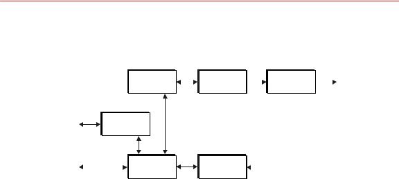
THEORY OF OPERATION
|
|
|
|
(2) |
(3) |
(4) |
|
||
|
|
|
|
RF |
RF Power |
RF Output |
|||
|
|
|
|
Driver/Exciter |
|||||
|
|
|
|
Amplifiers |
Measurement |
|
|||
|
|
|
|
|
|
|
|||
User Port |
|
(1) |
|
|
|
|
|
|
|
Analog I/O |
|
|
|
|
|||||
|
|
|
|
|
|
||||
Host Port |
|
|
(5) |
(6) |
|
|
|
||
|
|
|
Digital |
Sensor |
|
|
2965 |
||
|
|
|
|
||||||
|
|
|
|
|
Controller |
Electronics |
|
|
|
Figure 2 1. Cesar block diagram |
|
|
|
|
|||||
|
|
|
|
|
|
|
|
|
|
|
|
|
|
|
|
|
|
||
|
Module |
|
|
|
|
Description |
|
||
(1) |
Analog I/O |
|
|
This module provides the User interface. |
|
||||
|
|
|
|
||||||
(2) |
Driver/Exciter |
|
This module generates power at the designated output |
||||||
|
|
|
|
|
frequency to drive the main RF sections and contains the |
||||
|
|
|
|
|
CEX functions. |
|
|
|
|
|
|
|
|
|
|||||
(3) |
RF Amplifiers |
|
This module generates RF power. |
|
|||||
|
|
|
|
|
|
||||
(4) |
RF Power |
|
|
|
This module samples the output signal and sends it to the |
||||
Measurement |
|
|
|
sensor electronics. |
|
|
|
||
|
|
|
|
|
|
||||
(5) |
Digital |
|
|
|
This module is the main processor and data acquisition |
||||
Controller |
|
|
|
section. It also provides host communications through a host |
|||||
|
|
|
|
|
port. |
|
|
|
|
|
|
|
|
|
|
||||
(6) |
Sensor |
|
|
|
This module detects RF samples and sends them to the |
||||
Electronics |
|
|
|
microprocessor. |
|
|
|
|
|
|
|
|
|
|
|
|
|
|
|
2 2 |
Product Overview |
57023916-00B |

Cesar® Generator |
|
Chapter |
|
|
3 |
|
|
Specifications
PHYSICAL SPECIFICATIONS
Table 3 1.Physical specifications |
|
|
|
|
|
Description |
|
Specification |
General physical specifications |
|
|
|
|
|
Size |
88 mm (H) x 483 mm (W) x 500 mm (D) |
|
|
3.5″ (H) x 19″ (W) x 19.7″ (D) |
|
|
Dimensions include front panel mounting extensions. |
|
|
Dimensions do not include RF output, fan, connectors. |
|
|
|
|
Weight |
19.2 kg (42 lb) |
|
|
|
|
Mounting |
|
|
|
|
|
Clearance |
6 cm (2.36″) required on each side for airflow; 10.16 cm (4″) |
|
|
required at rear for cable connections |
|
|
|
|
Mounting |
19″ rack-mounting holes are provided on the generator front |
|
|
panel. |
|
|
|
|
Connectors |
|
|
|
|
|
AC input power |
IEC 60320 C14 inlet; mates with IEC 60320 C13 connector on |
|
|
power cord |
|
|
|
|
RF output |
N-Type, female connector |
|
|
|
|
User port connection (Analog |
There are two analog interface options available for the Cesar |
|
I/O) |
generator: |
|
|
• |
25-pin subminiature-D male |
|
• |
15-pin subminiature-D male |
|
|
|
Host port connection (serial I/ |
The Cesar generator has three host port communication |
|
O) |
interface options: |
|
|
• |
An RS-232 9-pin, female, shielded, subminiature-D |
|
|
connector |
|
• |
A PROFIBUS 9-pin, female, subminiature-D connector |
|
• |
An Ethernet Modbus/TCP connection |
|
|
|
CEX |
CEX BNC, female |
|
|
|
|
Front panel display |
LCD graphic display |
|
|
|
|
57023916-00B |
Specifications |
3 1 |

Advanced Energy
ELECTRICAL SPECIFICATIONS
Table 3 2.Electrical specifications |
|
|
|
||
|
|
|
|
|
|
Description |
|
|
Specification |
||
Electrical requirements |
|
|
|
|
|
|
|
|
|||
AC input voltage |
|
230 VAC (187 VAC to 253 VAC), 1 φ, neutral, with ground (PE) |
|||
|
|
|
|
|
|
AC line frequency |
|
50 Hz to 60 Hz |
|
|
|
|
|
|
|||
AC input current |
|
See the product label on your unit for the AC Current |
|||
|
|
|
|||
Input power |
|
Varies by your unit's AC input current. See the product label on |
|||
|
|
your unit for the AC Current. The input power specification is |
|||
|
|
based on full rated power and nominal line into 50 Ω load. |
|||
|
|
|
|
|
|
|
|
AC input current |
|
Input power |
|
|
|
2.8 A |
|
650 VA |
|
|
|
|
|
|
|
|
|
3 A |
|
680 VA |
|
|
|
|
|
|
|
|
|
4.6 A |
|
1050 VA |
|
|
|
|
|
|
|
|
|
4.8 A |
|
1100 VA |
|
|
|
|
|
|
|
|
|
6.5 A |
|
1490 VA |
|
|
|
|
|
|
|
|
|
6.8 A |
|
1550 VA |
|
|
|
|
|
|
|
|
|
8 A |
|
1780 VA |
|
|
|
|
|
|
|
|
|
10 A |
|
2225 VA |
|
|
|
|
|
|
|
|
|
|
|||
Power factor |
|
97% to 99% at full rated power, mid-frequency, and nominal line |
|||
|
|
into 50 Ω load |
|
|
|
|
|
|
|||
Overcurrent protection |
|
10 A, 250 V, T, high breaking capacity H electrical fuse (for |
|||
|
|
example, Schurter 0001.2514) |
|||
|
|
|
|||
Efficiency (line to load) |
|
Varies by unit. Effeciency listed below is typical at full-rated |
|||
|
|
power nominal line, into a 50 Ω load. |
|||
|
|
• 56% — Models 605, 6010 |
|||
|
|
• 58% — Models 403, 405, 4010 |
|||
|
|
• 63% — Models 273, 276, 2710 6 |
|||
|
|
• 65% — Models 026, 046, 133, 136 |
|||
|
|
• 66% — Models 0210, 0410, 1310, 1312 |
|||
|
|
|
|
|
|
Power specifications |
|
|
|
|
|
|
|
|
|||
RF frequency |
|
See your unit’s product label for the RF Frequency. Accuracy is |
|||
|
± 0.005% |
|
|
|
|
|
|
|
|
|
|
3 2 |
Specifications |
57023916-00B |

Cesar® Generator
Table 3 2.Electrical specifications (Continued) |
|
|
|
|||
|
|
|
|
|
|
|
Description |
|
|
|
Specification |
||
Minimum output power |
|
1% of your unit’s maximum output power. |
||||
|
|
The Cesar generator can operate below this level, but accuracy is |
||||
|
|
not guaranteed. |
|
|
|
|
|
|
|
||||
Maximum output power |
|
See your unit’s product label for the RF Power. |
||||
|
|
|
||||
Delivered power into |
|
Varies by output power (see your unit's label for RF Power) |
||||
mismatch |
|
|
|
|
|
|
|
|
RF power |
|
Delivered power |
|
|
|
|
|
|
|
||
|
|
300 W |
|
33% of nominal power |
|
|
|
|
|
|
|
|
|
|
|
500 W |
|
30% of nominal power |
|
|
|
|
|
|
|
|
|
|
|
600 W |
|
33% of nominal power |
|
|
|
|
|
|
|
|
|
|
|
1000 W |
|
20% of nominal power |
|
|
|
|
|
|
|
|
|
|
|
1200 W |
|
16% of nominal power |
|
|
|
|
|
|
|
||
|
|
|
||||
Maximum reflected |
|
Varies by power (see your unit's label for RF Power) |
||||
power |
|
|
|
|
|
|
|
|
RF power |
|
Maximum reflected power |
|
|
|
|
|
|
|
||
|
|
300 W |
|
100 W |
|
|
|
|
|
|
|
|
|
|
|
500 W |
|
175 W |
|
|
|
|
|
|
|
|
|
|
|
600 W, 1000 W, 1200 W |
|
200 W |
|
|
|
|
|
|
|
|
|
|
|
|
|
|
|
|
Load impedance |
|
50 Ω |
|
|
|
|
|
|
|
||||
Harmonics |
|
At full rated output, all harmonics are 45 dB below the RF output |
||||
|
|
signal when operated into a 50 Ω, nonreactive load impedance. All |
||||
|
|
spurious (nonharmonic) outputs are 60 dB below the RF output |
||||
|
|
signal. |
|
|
|
|
|
|
|
||||
RF power regulation |
|
1.0% of set point or 0.1% of full rated power, whichever is greater |
||||
|
|
|
|
|
|
|
RF power stability |
|
|
|
|
|
|
|
1.0% of set point or 0.2% of full rated power, whichever is greater |
|||||
RF pulse frequency |
|
• |
1 Hz to 10 kHz for units with RF Frequency of 2 MHz through |
|||
|
|
|
4 MHz |
|
|
|
|
|
• |
1 Hz to 30 kHz for units with RF Frequency of 13.56 MHz |
|||
|
|
|
through 60.0 MHz |
|
|
|
|
|
|
|
|
|
|
RF pulse duty cycle |
|
1% to 99% |
|
|
|
|
|
|
|
|
|
|
|
CEX Specifications |
|
|
|
|
|
|
|
|
|
|
|
|
|
|
|
|
|
|||
CEX input signal |
|
• |
TTL or Sine; 0 to + 19 dBm, 50 Ω for models 2710, 403, 405, |
|||
|
|
|
4010 |
|
|
|
|
|
• |
TTL for all other models |
|||
|
|
|
|
|
|
|
57023916-00B |
Specifications |
3 3 |

Advanced Energy |
|
|
|
||
Table 3 2.Electrical specifications (Continued) |
||
|
|
|
Description |
|
Specification |
CEX output signal |
• |
Sine; 7 dBm ± 3dB, 50 Ω for models 2710, 403, 405, 4010 |
|
• |
TTL for all other models |
|
|
|
COOLING SPECIFICATIONS
Table 3 3.Air cooling specifications |
|
|
|
Description |
Specification |
Cooling medium |
Air |
|
|
Minimum air flow |
118 m3/h (69.45 cfm) |
ENVIRONMENTAL SPECIFICATIONS
|
|
|
|
|
|
|
|
Table 3 4.Environmental standard specifications |
|
||||
|
|
|
|
|
|
|
|
Description |
|
Specification |
|||
|
Overvoltage |
|
Category II |
|
||
|
|
|
|
|
|
|
|
Pollution degree |
|
2 |
|
|
|
|
|
|
|
|
|
|
|
|
|
|
|
|
|
Table 3 5.Climatic specifications |
|
|
|
|
||
|
|
|
|
|
|
|
|
|
Temperature |
Relative Humidity |
|
Air Pressure |
|
Operating |
|
5°C to +35°C |
5% to 85%note 1 |
|
78.8 kPa to 106 kPa |
|
|
|
+41°F to +95°F |
+1 g/m3 to +25 g/m3 |
|
788 mbar to 1060 mbar |
|
|
|
|
|
|
|
Equivalent altitude: 2000 m |
|
|
|
|
|
|
to -500 m (6562′ to -1640′) |
|
|
|
|
|
|
|
Storage |
|
-25°C to +55°C |
5% to 95% |
|
78.8 kPa to 106 kPa |
|
|
|
-13°F to +131°F |
+1 g/m3 to +29 g/m 3 |
|
788 mbar to 1060 mbar |
|
|
|
|
|
|
|
Equivalent altitude: 2000 m |
|
|
|
|
|
|
to -500 m (6562′ to -1640′) |
|
|
|
|
|
|
|
3 4 |
Specifications |
57023916-00B |

|
|
|
|
Cesar® Generator |
|
|
|
|
|||
Table 3 5.Climatic specifications (Continued) |
|
|
|||
|
|
|
|
|
|
|
|
Temperature |
Relative Humidity |
Air Pressure |
|
|
Transportation |
-25°C to +70°C |
95% note 2 |
65.6 kPa to 106 kPa |
|
|
|
-13°F to +158°F |
+60 g/m3 note 3 |
656 mbar to 1060 mbar |
|
|
|
|
|
Equivalent altitude: 3500 m |
|
|
|
|
|
to -500 m (11480′ to -1640′) |
|
|
|
|
|
|
|
Non-condensing, no formation of ice
Maximum relative humidity when the unit temperature slowly increases, or when the unit temperature directly increases from -25°C to +30°C
note 3 Maximum absolute humidity when the unit temperature directly decreases from +70°C to +15°C
57023916-00B |
Specifications |
3 5 |

Advanced Energy
3 6 |
Specifications |
57023916-00B |
Loading...