


Cesar® Generator
Air-Cooled
User Manual
January 2013 57023916-00B


®
Cesar
Generator
Air-Cooled
User Manual
January 2013 57023916-00B
Advanced Energy
COPYRIGHT
This manual and the information contained herein are the proprietary property of Advanced
Energy Industries, Inc.
No part of this manual may be reproduced or copied without the express written permission of
Advanced Energy Industries, Inc. Any unauthorized use of this manual or its contents is
strictly prohibited. Copyright © 2011-2013 Advanced Energy Industries, Inc. All Rights
Reserved.
DISCLAIMER AND LIMITATION OF LIABILITY
The information contained in this manual is subject to change by Advanced Energy
Industries, Inc. without prior notice. Advanced Energy Industries, Inc. makes no warranty of
any kind whatsoever, either expressed or implied, with respect to the information contained
herein. Advanced Energy Industries, Inc. shall not be liable in damages, of whatever kind, as
a result of the reliance on or use of the information contained herein.
PRODUCT USAGE STATEMENT
WARNING :
Read this entire manual and all other publications pertaining to the work to
be performed before you install, operate, or maintain this equipment. Practice
all plant and product safety instructions and precautions. Failure to follow
instructions can cause personal injury and/or property damage. If the
equipment is used in a manner not specified by the manufacturer, the
protection provided by the equipment may be impaired. All personnel who
work with or who are exposed to this equipment must take precautions to
protect themselves against serious or possibly fatal bodily injury.
Advanced Energy Industries, Inc., (AE) provides information on its products
and associated hazards, but it assumes no responsibility for the after-sale
operation of the equipment or the safety practices of the owner or user.
NEVER DEFEAT INTERLOCKS OR GROUNDS.
TRADEMARKS
is a registered trademark of Advanced Energy Industries, Inc.
Cesar® is a registered trademark of Advanced Energy Industries, Inc.
iv 57023916-00B

Dressler® is a registered trademark of Advanced Energy Industries, Inc.
Epic® is a registered trademark of the Lapp Group.
HPG™ is a trademark of Advanced Energy Industries, Inc.
Modbus® is a registered trademark of Gould, Inc.
Navigator® is a registered trademark of Advanced Energy Industries, Inc.
Navio™ is a trademark of Advanced Energy Industries, Inc.
Neutrik® is a registered trademark of Neutrik Aktiengesellschaft.
Rectus® is a registered trademark of RECTUS, GmbH.
SERTO® is a registered trademark of SERTO Ltd.
Siemens® is a registered trademark of Siemens AG.
VarioMatch™ is a trademark of Advanced Energy Industries, Inc.
Windows® is a registered trademark of the Microsoft Corporation.
Cesar® Generator
Windows NT® is a registered trademark of the Microsoft Corporation.
CUSTOMER FEEDBACK
Advanced Energy’s technical writing staff has carefully developed this manual using
research-based document design principles. However, improvement is ongoing, and the
writing staff welcomes and appreciates customer feedback. Please send any comments on the
content, organization, or format of this user manual to:
• tech.writing@aei.com
To order a manual, please contact Technical Support:
• technical.support@aei.com
57023916-00B v

Advanced Energy
vi 57023916-00B

Cesar® Generator
Table of Contents
Chapter 1. Safety and Product Compliance Guidelines
Products Documented in this Manual ................................................................... 1-1
Important Safety Information ................................................................................. 1-1
Danger, Warning, and Caution Boxes in the Manual ............................................ 1-1
Safety Guidelines .................................................................................................. 1-2
Rules for Safe Installation and Operation ....................................................... 1-2
Interpreting Product Labels ................................................................................... 1-2
Product Compliance .............................................................................................. 1-3
Product Certification ....................................................................................... 1-3
Safety and EMC Directives and Standards .................................................... 1-4
Electromagnetic Compatibility (EMC) Directives and Standards ............. 1-4
Safety Directives and Standards .............................................................. 1-4
Conditions of Use ........................................................................................... 1-5
Interlocks and Limiting Conditions ........................................................................ 1-6
Chapter 2. Product Overview
General Description .............................................................................................. 2-1
Theory of Operation .............................................................................................. 2-2
Chapter 3. Specifications
Physical Specifications .......................................................................................... 3-1
Electrical Specifications ........................................................................................ 3-2
Cooling Specifications ........................................................................................... 3-4
Environmental Specifications ................................................................................ 3-4
Chapter 4. Communication Controls
Diagnostic Interface .............................................................................................. 4-1
Matching Interface ................................................................................................. 4-1
Matching Interface Connector ........................................................................ 4-1
Matching Interface Pin Descriptions ............................................................... 4-1
User Port ............................................................................................................... 4-3
25-Pin User Port ............................................................................................. 4-4
User Port Connector ................................................................................ 4-4
Satisfying Minimal Requirements for the 25-pin User Port ...................... 4-4
25-pin User Port Cabling Requirements .................................................. 4-5
Activating the 25-Pin User Port ................................................................ 4-5
Resolving Error Displays When Using the 25-Pin User Port ................... 4-6
57023916-00B viiTable of Contents

Advanced Energy
25-pin User Port Pin Descriptions and Wiring Diagrams ......................... 4-6
15-Pin User Port ........................................................................................... 4-18
User Port Connector .............................................................................. 4-18
Satisfying Minimal Requirements for the 15-pin User Port .................... 4-18
15-pin User Port Cabling Requirements ................................................ 4-20
Activating the 15-Pin User Port .............................................................. 4-20
Resolving Error Displays When Using the 15-Pin User Port ................. 4-21
15-pin User Port Pin Descriptions and Wiring Diagrams ....................... 4-21
Cesar Generator Host Port ................................................................................. 4-31
RS-232 Interface .......................................................................................... 4-31
RS-232 Connector ................................................................................. 4-32
RS-232 Port Pin Descriptions ................................................................ 4-32
AE Bus Transmission Parameters ......................................................... 4-32
AE Bus Protocol ..................................................................................... 4-33
Creating an Ideal Communications Transaction .................................... 4-35
PROFIBUS Interface .................................................................................... 4-37
PROFIBUS Connector ........................................................................... 4-38
PROFIBUS Port Pin and Signal Descriptions ........................................ 4-38
PROFIBUS Cabling and Termination .................................................... 4-38
AE PROFIBUS Protocol ......................................................................... 4-39
PROFIBUS Command Structure ........................................................... 4-42
Ethernet Interface ......................................................................................... 4-44
Ethernet Connector and Indicators ........................................................ 4-44
Understanding AE TCP Commands and Register Types (FC23) .......... 4-45
Using Modbus/TCP FC23 ...................................................................... 4-46
AE Bus Commands ...................................................................................... 4-50
Activating Host Port Remote Control (AE Bus Command 14) ............... 4-51
AE Bus Command Status Response (CSR) Codes ............................... 4-53
AE Bus Port Command Set ................................................................... 4-54
Chapter 5. Installation, Setup, and Operation
Preparing to Install the Unit ................................................................................... 5-1
Spacing Requirements ................................................................................... 5-1
Dimensional Drawings .................................................................................... 5-1
Installation Requirements ............................................................................... 5-3
Tools Required for Installation ........................................................................ 5-3
Unpacking the Unit ......................................................................................... 5-4
Lifting the Unit .......................................................................................... 5-4
Installing the Unit ................................................................................................... 5-5
Mounting ......................................................................................................... 5-5
Grounding ....................................................................................................... 5-5
Connecting Output Power .............................................................................. 5-6
To Connect Output Power ....................................................................... 5-6
Connecting Communication Interfaces ........................................................... 5-8
To Connect the Communication Interfaces .............................................. 5-8
Connecting the Generator to a System Interlock Loop ................................... 5-9
Satisfying the Interlock With a 25-pin User Port ...................................... 5-9
Satisfying the Interlock With a 15-pin User Port ...................................... 5-9
viii 57023916-00BTable of Contents

Cesar® Generator
Connecting a VarioMatch or Navio Match Network (Optional) ....................... 5-9
Connecting Common Exciter (CEX) Circuitry (Optional) .............................. 5-10
To Make the CEX Connections .............................................................. 5-10
Connecting AC Input (Mains) Power ............................................................ 5-11
Connecting and Setting Ethernet (Modbus/TCP) Communication ............... 5-12
To Connect for Ethernet Communication ............................................... 5-12
Setting the IP Configuration for Ethernet Communication ..................... 5-12
First Time Operation ........................................................................................... 5-13
Operating the Cesar Generator for the First Time With the User Port ......... 5-14
To Operate the Cesar Generator for the First Time With the 25-pin
User Port .............................................................................................. 5-14
To Operate the Cesar Generator for the First Time With the 15-pin
User Port .............................................................................................. 5-15
Operating the Cesar Generator for the First Time With the Host Port .......... 5-16
Operating the Cesar Generator for the First Time With the Front Panel . ..... 5-17
Cesar Generator Front Panel .............................................................................. 5-18
Front Panel Control Elements ...................................................................... 5-19
Using the Front Panel Program Menu .......................................................... 5-20
Accessing the Program Menu ................................................................ 5-20
Entering Values in the Program Menu ................................................... 5-21
Front Panel Program Menu Tree ........................................................... 5-22
Viewing Measurements in the Display .......................................................... 5-23
Remote Control Operation .................................................................................. 5-24
Viewing and Using the Front Panel when in Remote Control Mode ............. 5-24
RF Control and Resetting Errors .................................................................. 5-25
Normal Operation ................................................................................................ 5-26
Setting Regulation Mode .............................................................................. 5-26
Determining the Regulation Mode Setting ............................................. 5-27
To Set Regulation Mode ........................................................................ 5-28
Setting the Pulse Function ............................................................................ 5-29
Selecting Internal or External Pulsing .................................................... 5-29
Changing the Pulse Input Configuration Settings .................................. 5-30
To Turn Off Pulsing ................................................................................ 5-31
Creating Recipes (RF on/off, Slew Rate, Power Ramping) .......................... 5-31
Creating an RF On/Off Ramp Recipe .................................................... 5-32
Creating a Slew Rate Recipe ................................................................. 5-32
Creating a Power Ramp Recipe ............................................................ 5-33
To Turn Off the Recipe Settings Feature ............................................... 5-34
Recipe Settings Operating Screen ......................................................... 5-34
Setting and Disabling Remote Control Override ........................................... 5-35
Selecting Remote Control Override ....................................................... 5-35
Disabling Remote Control Override ....................................................... 5-36
Setting and Turning Off the Target Lifetime Feature .................................... 5-37
Setting Target Lifetime Parameters ....................................................... 5-37
To Turn Off the Target Lifetime Feature ................................................ 5-37
Resetting a Target Lifetime .................................................................... 5-38
Changing Reflected Power Settings ............................................................. 5-38
Changing the Device Configuration Settings ................................................ 5-39
To Change the Default Device Configuration Settings .......................... 5-40
Setting and Using Preset Generator Settings for Different Applications . ..... 5-41
57023916-00B ixTable of Contents

Advanced Energy
To Store a Preset ................................................................................... 5-41
To Erase a Preset .................................................................................. 5-42
To Use a Preset ..................................................................................... 5-42
Controlling a VarioMatch or Navio Match Network Attached to the
Generator .......................................................................................................... 5-42
Determining the Current Match Network Tune Setting ................................. 5-43
Setting Tune Control ..................................................................................... 5-43
Determining Automatic Tuning Presets ........................................................ 5-45
Adjusting the Capacitors When in Manual Tune .......................................... 5-45
Using the Cable Attenuation Feature .................................................................. 5-47
Cable Attenuation Description ...................................................................... 5-47
Forward Power Calculation .................................................................... 5-48
Reflected Power Calculation .................................................................. 5-48
Cable Attenuation and Reflected Power Settings ......................................... 5-49
Connecting to an Ethernet-Enabled Unit With a Web Browser ........................... 5-49
Chapter 6. Troubleshooting and Global Services
Before Contacting AE Global Services ................................................................. 6-1
Checks With Power Off .................................................................................. 6-1
Checks With Power On .................................................................................. 6-2
Troubleshooting Checklists ............................................................................ 6-2
General Troubleshooting ......................................................................... 6-2
Matching Network Troubleshooting ......................................................... 6-3
Interlock Not Satisfied ..................................................................................... 6-3
Front Panel Display (LCD) Not Lit .................................................................. 6-4
Fuse is Blown ................................................................................................. 6-4
Communication Problems .............................................................................. 6-4
Capacitor Failure ............................................................................................ 6-5
Incorrect Input Voltage ................................................................................... 6-5
Improper Impedance Range ........................................................................... 6-5
Improper RF Connection or Cabling ............................................................... 6-6
Improper Grounding ....................................................................................... 6-6
Improper Matching Interface Connection ....................................................... 6-6
Improper Tuning Adjustment .......................................................................... 6-7
Troubleshooting Using Error Codes ...................................................................... 6-7
Fault and Warning Types and Clearing Faults ............................................... 6-7
Error Code Descriptions and Resolutions ...................................................... 6-8
Warning Message Descriptions and Resolutions ......................................... 6-10
Communication Warning Descriptions and Resolutions ............................... 6-12
AE Global Services ............................................................................................. 6-14
Returning Units for Repair ................................................................................... 6-15
Decommissioning the Unit .................................................................................. 6-15
x 57023916-00BTable of Contents

Cesar® Generator
List of Tables
Table 1-1. Cesar limiting conditions ...................................................................... 1-7
Table 3-1. Physical specifications ......................................................................... 3-1
Table 3-2. Electrical specifications ........................................................................ 3-2
Table 3-3. Air cooling specifications ...................................................................... 3-4
Table 3-4. Environmental standard specifications ............................................... 3-4
Table 3-5. Climatic specifications .......................................................................... 3-4
Table 4-1. Matching interface pin descriptions ...................................................... 4-1
Table 4-2. User Port Signal Specifications ............................................................ 4-7
Table 4-3. 25-Pin User Port Pin Descriptions ...................................................... 4-8
Table 4-4. 15-Pin User Port Pin Descriptions .................................................... 4-21
Table 4-5. Setting regulation mode with 15-pin User Port pins 1 and 2 .............. 4-24
Table 4-6. RS-232 port pin descriptions .............................................................. 4-32
Table 4-7. AE Bus byte structure ........................................................................ 4-35
Table 4-8. PROFIBUS port pin and signal descriptions ...................................... 4-38
Table 4-9. Baud rate and cable lengths .............................................................. 4-38
Table 4-10. PROFIBUS status LEDs .................................................................. 4-40
Table 4-11. Configuration of PROFIBUS download packet bytes ....................... 4-42
Table 4-12. PROFIBUS upload packet status bit flags ...................................... 4-43
Table 4-13. Packet format for FC23 send ........................................................... 4-46
Table 4-14. Packet format for FC23 response .................................................... 4-47
Table 4-15. Packet format for FC23 exception error ........................................... 4-48
Table 4-16. Packet format for command 168 send ............................................. 4-49
Table 4-17. Packet format for command 168 response ...................................... 4-50
Table 4-18. AE Bus command 14 remote control settings, resets, and
overrides ............................................................................................................ 4-52
Table 4-19. AE Bus command status response (CSR) codes ............................ 4-53
Table 4-20. AE Bus Commands .......................................................................... 4-54
Table 4-21. Remote control override settings (command 29) ............................. 4-81
Table 5-1. Input connector pin description ......................................................... 5-11
Table 5-2. Remote control mode displayed on the front panel ........................... 5-25
Table 5-3. RF on/off control ................................................................................ 5-26
Table 5-4. Adjusting VarioMatch match network capacitors .............................. 5-46
Table 6-1. Error codes .......................................................................................... 6-8
Table 6-2. Warning messages ............................................................................ 6-11
Table 6-3. Communication warning messages ................................................... 6-12
Table 6-4. AE Global Services 24 X 7 contact information ................................. 6-15
57023916-00B xiList of Tables

Advanced Energy
xii 57023916-00BList of Tables

Cesar® Generator
List of Figures
Figure 2-1. Cesar block diagram ........................................................................... 2-2
Figure 4-1. Matching interface connector .............................................................. 4-1
Figure 4-2. User Port connector, 25 Pin ................................................................ 4-4
Figure 4-3. Reflected power monitor (pins 2 and 15) .......................................... 4-13
Figure 4-4. Forward/Load power monitor (pins 3 and 16) ................................... 4-13
Figure 4-5. RF POWER ON signal wiring (pins 4 and 17) .................................. 4-13
Figure 4-6. SET POINT signal wiring (pins 5 and 18) ......................................... 4-14
Figure 4-7. RF FORWARD POWER/DC BIAS REGULATION wiring (pins 6
and 19) .............................................................................................................. 4-14
Figure 4-8. DC BIAS MONITOR signal wiring (pins 7 and 20) (units with DC
Bias In) .............................................................................................................. 4-14
Figure 4-9. DC BIAS MONITOR signal wiring (pins 7 and 20) (units with DC
Bias Out) ............................................................................................................ 4-15
Figure 4-10. RF FORWARD/LOAD REGULATION signal wiring (pins 8 and
21) ..................................................................................................................... 4-15
Figure 4-11. INTERLOCK LOOP signal wiring (pins 10 and 23) ........................ 4-16
Figure 4-12. +15 VOLT DC signal wiring (pins 13 and 21) ................................. 4-16
Figure 4-13. SET POINT STATUS signal wiring (pins 14 and 1) ........................ 4-17
Figure 4-14. OVERTEMPERATURE signal wiring (pins 22 and 9) ..................... 4-17
Figure 4-15. INTERLOCK SATISFIED signal wiring (pins 24 and 11) ................ 4-17
Figure 4-16. BLANKING/PULSING signal wiring (pins 25 and 19) ..................... 4-18
Figure 4-17. User Port connector, 15 Pin ............................................................ 4-18
Figure 4-18. Interlock interface connector ........................................................... 4-19
Figure 4-19. OPERATING MODE A wiring diagram (pins 1 and 8) .................... 4-25
Figure 4-20. OPEATING MODE B wiring diagram (pins 2 and 8) ....................... 4-25
Figure 4-21. READY STATUS wiring diagram (pins 3 and 8) ............................. 4-26
Figure 4-22. ERROR wiring diagram (pins 4 and 8) ........................................... 4-26
Figure 4-23. MAXIMUM POWER LEVEL REACHED wiring diagram (pins 5
and 8) ................................................................................................................ 4-27
Figure 4-24. RF ON wiring diagram (pins 6 and 8) ............................................. 4-27
Figure 4-25. INTERFACE VOLTAGE wiring diagram (pins 7 and 8) .................. 4-28
Figure 4-26. BLANKING/PULSING MODE wiring diagram (pins 9 and 8) .......... 4-28
Figure 4-27. RF POWER ON wiring diagram (pins 10 and 8) ............................. 4-29
Figure 4-28. DC BIAS SET POINT wiring diagram (pins 11 and 8) .................... 4-29
Figure 4-29. RF POWER SET POINT wiring diagram (pins 12 and 8) ............... 4-29
Figure 4-30. TEST VOLTAGE FOWARD POWER wiring diagram (pins 13
and 8) ................................................................................................................ 4-30
Figure 4-31. TEST VOLTAGE REFLECTED POWER wiring diagram (pins
14 and 8) ........................................................................................................... 4-30
Figure 4-32. TEST VOLTAGE FOR DC BIAS wiring diagram (pins 15 and
8) ....................................................................................................................... 4-31
Figure 4-33. RS-232 port connector .................................................................... 4-32
Figure 4-34. Graphic representation of a message packet ................................. 4-34
Figure 4-35. AE Bus communications transaction .............................................. 4-36
Figure 4-36. Communications transaction example ............................................ 4-37
57023916-00B xiiiList of Figures

Advanced Energy
Figure 4-37. PROFIBUS port connector ............................................................. 4-38
Figure 4-38. Example of a segment .................................................................... 4-39
Figure 4-39. Ethernet connector and indicators .................................................. 4-45
Figure 5-1. Cesar unit dimensions ........................................................................ 5-2
Figure 5-2. Cesar rear view ................................................................................... 5-3
Figure 5-3. RF Output connector .......................................................................... 5-6
Figure 5-4. RF cover ............................................................................................. 5-6
Figure 5-5. RF / User Port interlock adapter cable ................................................ 5-7
Figure 5-6. RF / User Port interlock adapter cable, attached to unit ..................... 5-8
Figure 5-7. CEX Connector ................................................................................. 5-10
Figure 5-8. AC Input (Mains) connector .............................................................. 5-11
Figure 5-9. Front panel ........................................................................................ 5-19
Figure 5-10. Front panel program menu tree ...................................................... 5-22
Figure 5-11. Front panel program menu tree (continued) ................................... 5-23
Figure 5-12. Generator with no cable attenuation ............................................... 5-48
Figure 5-13. Generator with cable attenuation .................................................... 5-48
Figure 6-1. Input (Mains) connector and fuse box ................................................ 6-4
xiv 57023916-00BList of Figures
Cesar® Generator
1027
Chapter
Safety and Product Compliance Guidelines
PRODUCTS DOCUMENTED IN THIS MANUAL
This user manual documents air-cooled Cesar generators.
The following part numbers include some non-standard features, which will be called
out where they apply:
• 61300129: DC Bias Out on the User Port. All other part numbers: DC Bias In
on the User Port.
• 61300121: 0 V to 5 V scaling on the User Port. All other part numbers: 0 V to
10 V scaling on the User Port.
1
IMPORTANT SAFETY INFORMATION
To ensure safe installation and operation of the Advanced Energy Cesar unit, read
and understand this manual before attempting to install and operate this unit. At a
minimum, read and follow the safety guidelines, instructions, and practices.
DANGER, WARNING, AND CAUTION BOXES IN THE MANUAL
This symbol represents important notes concerning potential harm to people, this
unit, or associated equipment. Advanced Energy includes this symbol in Danger,
Warning, and Caution boxes to identify specific levels of hazard seriousness.
DANGER:
DANGER indicates an imminently hazardous situation that, if not avoided,
will result in death or serious injury. DANGER is limited to the most extreme
situations.
57023916-00B Safety and Product Compliance Guidelines 1‑1

Advanced Energy
WARNING:
WARNING indicates a potentially hazardous situation that, if not avoided,
could result in death or serious injury, and/or property damage.
CAUTION:
CAUTION indicates a potentially hazardous situation that, if not avoided,
could result in minor or moderate injury, and/or property damage. CAUTION
is also used for property-damage-only accidents.
SAFETY GUIDELINES
Review the following information before attempting to install and operate the
product.
Rules for Safe Installation and Operation
Please note the following rules:
• Do not attempt to install or operate this equipment without proper training.
• There are no user-serviceable parts inside the unit. Refer servicing to trained
service personnel.
• Ensure that this unit is properly grounded.
• Ensure that all cables are properly connected.
• Verify that input line voltage and current capacity are within specifications
before turning on the power supplies.
• Use proper electrostatic discharge (ESD) precautions.
• Always be careful around this equipment.
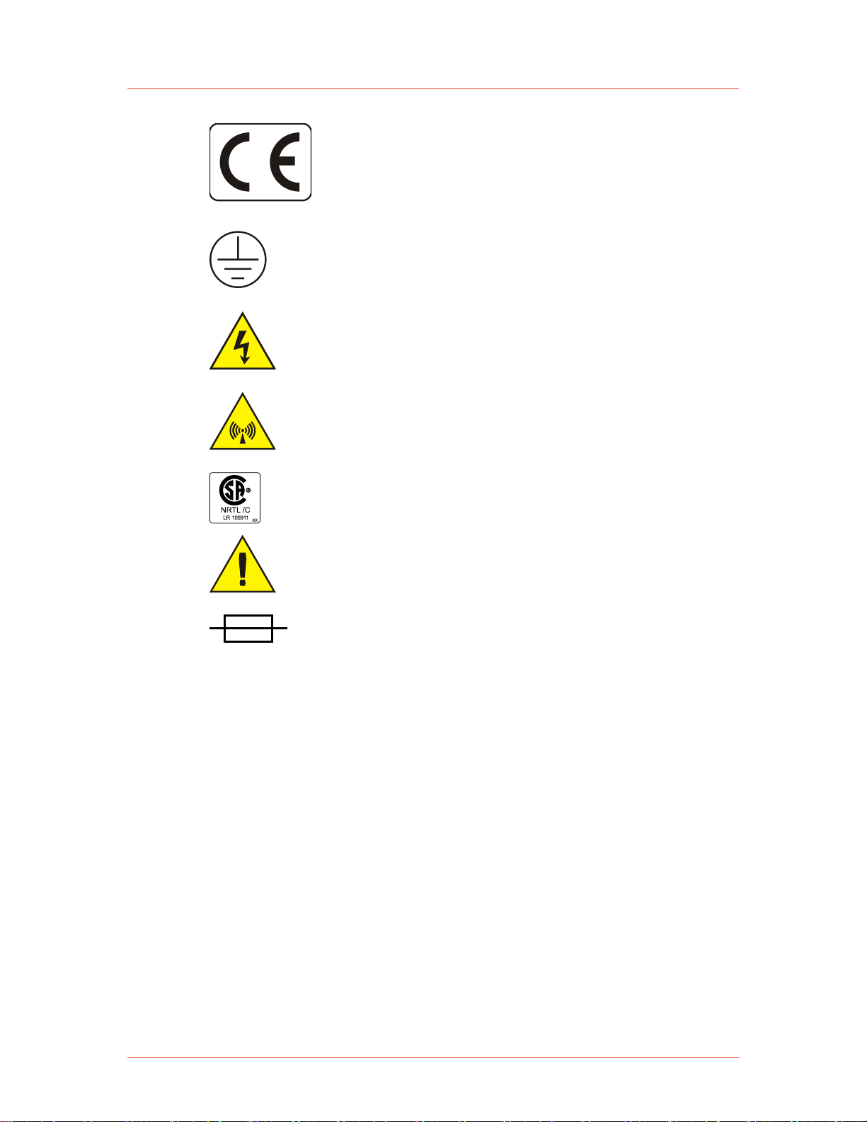
INTERPRETING PRODUCT LABELS
The following labels may appear on your unit:
1‑2 Safety and Product Compliance Guidelines 57023916-00B
1020
CE label
1029
1028
1030
1027
Protective Earth ground
Hazardous voltage
Nonionizing radiation
Cesar® Generator
PRODUCT COMPLIANCE
The following sections include information about unit compliance and certification,
including the conditions of use required to be in compliance with the standards and
directives.
Product Certification
NRTL: Nationally Recognized Testing
Laboratory
Refer to manual for more information
Electrical fuse
Certain options of this product may be certified according to the list below.
For more information, refer to the Certificate or Letter of Conformity (US) or
Declaration of Conformity (EU) accompanying the product.
• NRTL – Safety certified by CSA International, a Nationally Recognized
Testing Laboratory
• CE Marking – Self-declaration, assessed by AE Corporate Compliance
57023916-00B Safety and Product Compliance Guidelines 1‑3

Advanced Energy
• EMC measurements – Verified by the AE Corporate Compliance Lab and/or an
accredited third party lab
Safety and EMC Directives and Standards
Certain options of this unit have been tested for and comply with the following
electromagnetic compatibility (EMC) and safety directives and standards and
industry guidelines.
☞ Important
This device must be installed and used only in compliance with the directives
and standards listed in addition to EN 60204 (IEC 60204) and applicable
requirements.
☞ Important
This equipment must be installed and used in accordance with the Conditions
of Use described in this manual. If this equipment is expanded, modified, or
installed into a larger system, the user is responsible to guarantee the
compliance of the overall system. If this equipment is used with external
components, the user must ensure that the Safety and EMC requirements are
not violated.
ELECTROMAGNETIC COMPATIBILITY (EMC) DIRECTIVES AND STANDARDS
• 2004/108/EC
EC Council directive on the approximation of the laws of the Member States
relating to electromagnetic compatibility (EMC Directive)
• 47 CFR Part 18
Code of Federal Regulations—Limits and methods of measurement of radio
interference characteristics of industrial, scientific, and medical equipment
• EN 55011
Limits and methods of measurement of radio disturbance characteristics of
industrial, scientific, medical (ISM) radio frequency equipment (Class A, Group
2) (CISPR 11)
• EN 61000-6-2
Electromagnetic Compatibility (generic immunity standard—industrial)
SAFETY DIRECTIVES AND STANDARDS
• 2006/95/EC
EC Council directive on the harmonization of the laws of the Member States
relating to electrical equipment designed for use within certain voltage limits
(LVD - Low Voltage Directive)
• EN 61010-1
1‑4 Safety and Product Compliance Guidelines 57023916-00B

Safety requirements for Electrical Equipment for Measurement, Control, and
Laboratory Use - Part 1: General Requirements
Conditions of Use
To comply with the stated directives and standards, you must meet the following
conditions of use:
DANGER:
RISK OF DEATH OR BODILY INJURY. Disconnect and lockout/tagout all
sources of input power before working on this unit or anything connected to
it.
• Before making any other connection to this device, connect the auxiliary
Protective Earth ground terminal to a local earth ground with a copper wire that
is sized according to the applicable requirements.
• Install and operate this device only in accordance with the listed safety
guidelines and all other applicable directives and standards specific to your
process and application.
Cesar® Generator
• Install and operate this device in an overvoltage category II or better
installation.
• Install and operate this device only in a pollution degree 2 or better
environment, which means an indoor location such as a computer room, office,
or factory floor where only nonconductive pollution occurs during operation.
Occasionally, condensation causes temporary conductivity when the device is
not operating.
• Install this device so that it is fully enclosed by a rack or other enclosure. The
rack or enclosure must be metal and either reinforced or of sufficient thickness
to resist both of the following tests:
◦ A steady force of 445 N, applied through a steel hemisphere 12.7 mm in
diameter
◦ An impact of 7 J, applied by dropping or swinging a 0.53 kg, 50 mm diameter
steel sphere
◦ Following the tests, there must be still a minimum clearance of 12.7 mm
between the rack or enclosure and the power supply. There shall be no
deformation of the power supply.
• The on/off power switch does not completely disconnect the AC input. If the
AC power cord is not accessible after installation, a separate external switch is
required to disconnect AC power.
• The AC line cord must be terminated according to the applicable requirements.
• Use only shielded cables on the serial and user communications interfaces.
57023916-00B Safety and Product Compliance Guidelines 1‑5

Advanced Energy
• Install and operate this device with a 16 A (maximum) circuit breaker switch on
the AC input to provide the required over-current protection. The circuit breaker
switch must be easily accessible and near the device.
• Install this device so that the input power connection is inaccessible to the user.
• Install this device so that the output power connection is inaccessible to the
user.
INTERLOCKS AND LIMITING CONDITIONS
WARNING:
Advanced Energy products only include interlocks when required by product
specification. Interlocks in Advanced Energy products are not intended to
meet or satisfy safety requirements. Where interlocks exist, you must still
meet and satisfy safety requirements. The presence of interlocks does not
imply operator protection.
All Cesar generators have an Interlock interface. This interface allows you to
integrate any Cesar generator into a system interlock loop that can interrupt the
delivered RF power.
Even if you do not connect this Cesar generator into a larger system interlock loop,
you must make the proper interlock loop connections for the unit to enable RF power.
The Cesar generator may be shipped with an interlock jumper plug that provides a
connection between the User Port interlock pins. You can use this jumper plug to
satisfy the interlock and enable operation in situations where you do not intend to
connect the remaining pins on this port.
☞ Important
Using the interlock jumper plug disables the interlock function.
☞ Important
Interlock does not switch the generator on/off. If an interlock is not satisfied,
the Cesar generator will issue an interlock error. Interlock errors must be
resolved, so you must switch RF off (via the RS-232 or User Port) or resolve
the error (via the front panel) before you can switch on RF power again.
Your unit may include an RF cover. For units with an RF cover:
• RF output is disabled when the cover is removed. Ensure that the RF cover is in
place.
• In addition to the interlock jumper plug for the User Port and the RF cover,
your unit uses an RF / User Port interlock adapter cable. For information on
connecting this cable, see “Connecting Output Power” on page 5-6.
1‑6 Safety and Product Compliance Guidelines 57023916-00B

Cesar® Generator
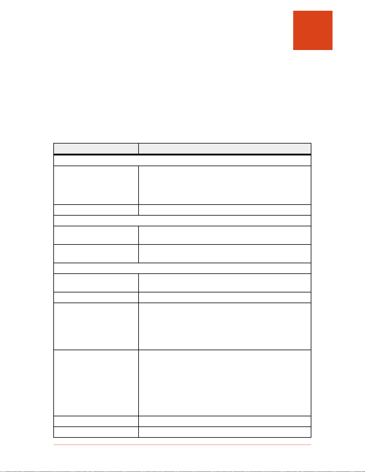
In addition, the Cesar generator includes specific limits that are described in
Table 1-1. The errors generated by exceeding these limits are described in
“Troubleshooting Using Error Codes” on page 6-7.
Table 1‑1. Cesar limiting conditions
Limit Unit Response and User Resolution
RF power limit When the unit reaches the forward or reflected power limit, the
unit reduces forward power to remain within the limits. Output
is not at set point.
Overtemperature When the unit exceeds the specified maximum temperature, RF
power shuts off, and the unit displays an error code.
Current limit When the voltage or the current exceeds the limit of the
internal SMPS, the unit reduces output to remain within the
limits. Output is not at set point.
External pulse frequency limit When the external pulse frequency exceeds the limit, the unit
turns RF power off.
Target lifetime limit The target lifetime warning occurs when the target lifetime
reaches the user-set limit. This warning does not affect the
operation of the unit.
57023916-00B Safety and Product Compliance Guidelines 1‑7

Advanced Energy
1‑8 Safety and Product Compliance Guidelines 57023916-00B

Cesar® Generator
Chapter
Product Overview
GENERAL DESCRIPTION
AE Cesar RF power generators are Class E Switched Mode Amplifiers for Radio
Frequency (CESAR), a new generation of versatile RF power supplies for
semiconductor production, and general plasma processing. This generator employs
parallel excited circuitry in a compact, 19″ rack-mountable designs. Typical
applications include sputtering, reactive ion etching, RF bias, plasma
polymerization, plasma surface treatment, and CO2 laser systems.
The Cesar generator incorporates advanced switch mode technology. This highly
efficient, resonant switching concept results in reduced energy costs, reduced
downtimes, and a longer lifetime for the unit.
Designed to regulate power into a broad range of output impedances, the Cesar
generator can operate in forward power, real power, or DC bias regulation mode In
addition, you can add a cable attenuation variable to the power regulation setting.
2
Both manual and automatic tuning control support operation into a fixed impedance
matching network, which simplifies system complexity, increases reliability, and
improves process-to-process repeatability.
You can control and configure the Cesar generator using any of the following
methods:
• Remotely through an analog User Port.
• Remotely through a communication host port.
• Using the front panel, which features a liquid crystal display (LCD) with an
easy-to-use menu.
The Cesar generator operates from an AC power source. The unit can tolerate
arbitrary phase rotation of the input power connections. The generator is air-cooled
and has all power and interface-port connections at the rear of the generator.
57023916-00B Product Overview 2‑1
2965
(2)
Driver/Exciter
(1)
Analog I/O
(5)
Digital
Controller
(3)
RF
Amplifiers
(4)
RF Power
Measurement
(6)
Sensor
Electronics
User Port
Host Port
RF Output
Advanced Energy
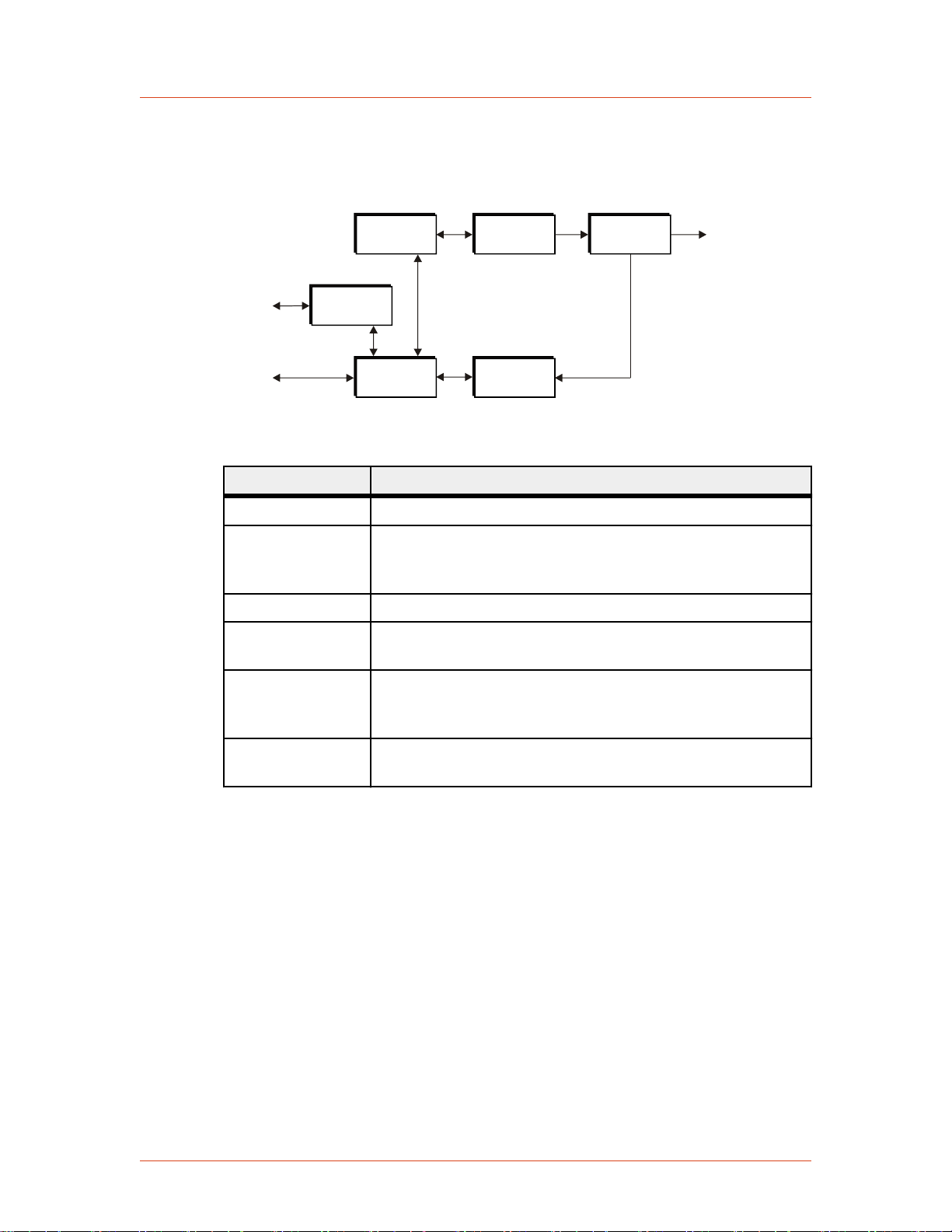
THEORY OF OPERATION
Figure 2‑1. Cesar block diagram
Module Description
(1) Analog I/O This module provides the User interface.
(2) Driver/Exciter This module generates power at the designated output
frequency to drive the main RF sections and contains the
CEX functions.
(3) RF Amplifiers This module generates RF power.
(4) RF Power
Measurement
(5) Digital
Controller
This module samples the output signal and sends it to the
sensor electronics.
This module is the main processor and data acquisition
section. It also provides host communications through a host
port.
(6) Sensor
Electronics
This module detects RF samples and sends them to the
microprocessor.
2‑2 Product Overview 57023916-00B
Cesar® Generator
Chapter
Specifications
PHYSICAL SPECIFICATIONS
Table 3‑1. Physical specifications
Description Specification
General physical specifications
Size 88 mm (H) x 483 mm (W) x 500 mm (D)
3.5″ (H) x 19″ (W) x 19.7″ (D)
Dimensions include front panel mounting extensions.
Dimensions do not include RF output, fan, connectors.
3
Weight 19.2 kg (42 lb)
Mounting
Clearance 6 cm (2.36″) required on each side for airflow; 10.16 cm (4″)
required at rear for cable connections
Mounting 19″ rack-mounting holes are provided on the generator front
panel.
Connectors
AC input power IEC 60320 C14 inlet; mates with IEC 60320 C13 connector on
power cord
RF output N-Type, female connector
User port connection (Analog
I/O)
Host port connection (serial I/O)The Cesar generator has three host port communication
There are two analog interface options available for the Cesar
generator:
• 25-pin subminiature-D male
• 15-pin subminiature-D male
interface options:
• An RS-232 9-pin, female, shielded, subminiature-D
connector
• A PROFIBUS 9-pin, female, subminiature-D connector
• An Ethernet Modbus/TCP connection
CEX CEX BNC, female
Front panel display LCD graphic display
57023916-00B Specifications 3‑1
Advanced Energy
ELECTRICAL SPECIFICATIONS
Table 3‑2. Electrical specifications
Description Specification
Electrical requirements
AC input voltage 230 VAC (187 VAC to 253 VAC), 1 φ, neutral, with ground (PE)
AC line frequency 50 Hz to 60 Hz
AC input current See the product label on your unit for the AC Current
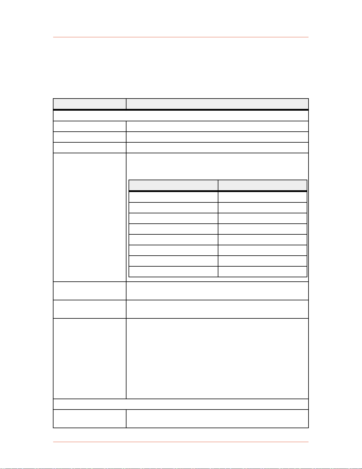
Input power Varies by your unit's AC input current. See the product label on
your unit for the AC Current. The input power specification is
based on full rated power and nominal line into 50 Ω load.
AC input current Input power
2.8 A 650 VA
3 A 680 VA
4.6 A 1050 VA
4.8 A 1100 VA
6.5 A 1490 VA
6.8 A 1550 VA
8 A 1780 VA
10 A 2225 VA
Power factor 97% to 99% at full rated power, mid-frequency, and nominal line
into 50 Ω load
Overcurrent protection 10 A, 250 V, T, high breaking capacity H electrical fuse (for
example, Schurter 0001.2514)
Efficiency (line to load) Varies by unit. Effeciency listed below is typical at full-rated
power nominal line, into a 50 Ω load.
• 56% — Models 605, 6010
• 58% — Models 403, 405, 4010
• 63% — Models 273, 276, 2710 6
• 65% — Models 026, 046, 133, 136
• 66% — Models 0210, 0410, 1310, 1312
Power specifications
RF frequency See your unit’s product label for the RF Frequency. Accuracy is
± 0.005%
3‑2 Specifications 57023916-00B

Table 3‑2. Electrical specifications (Continued)
Description Specification
Minimum output power 1% of your unit’s maximum output power.
The Cesar generator can operate below this level, but accuracy is
not guaranteed.
Maximum output power See your unit’s product label for the RF Power.
Cesar® Generator
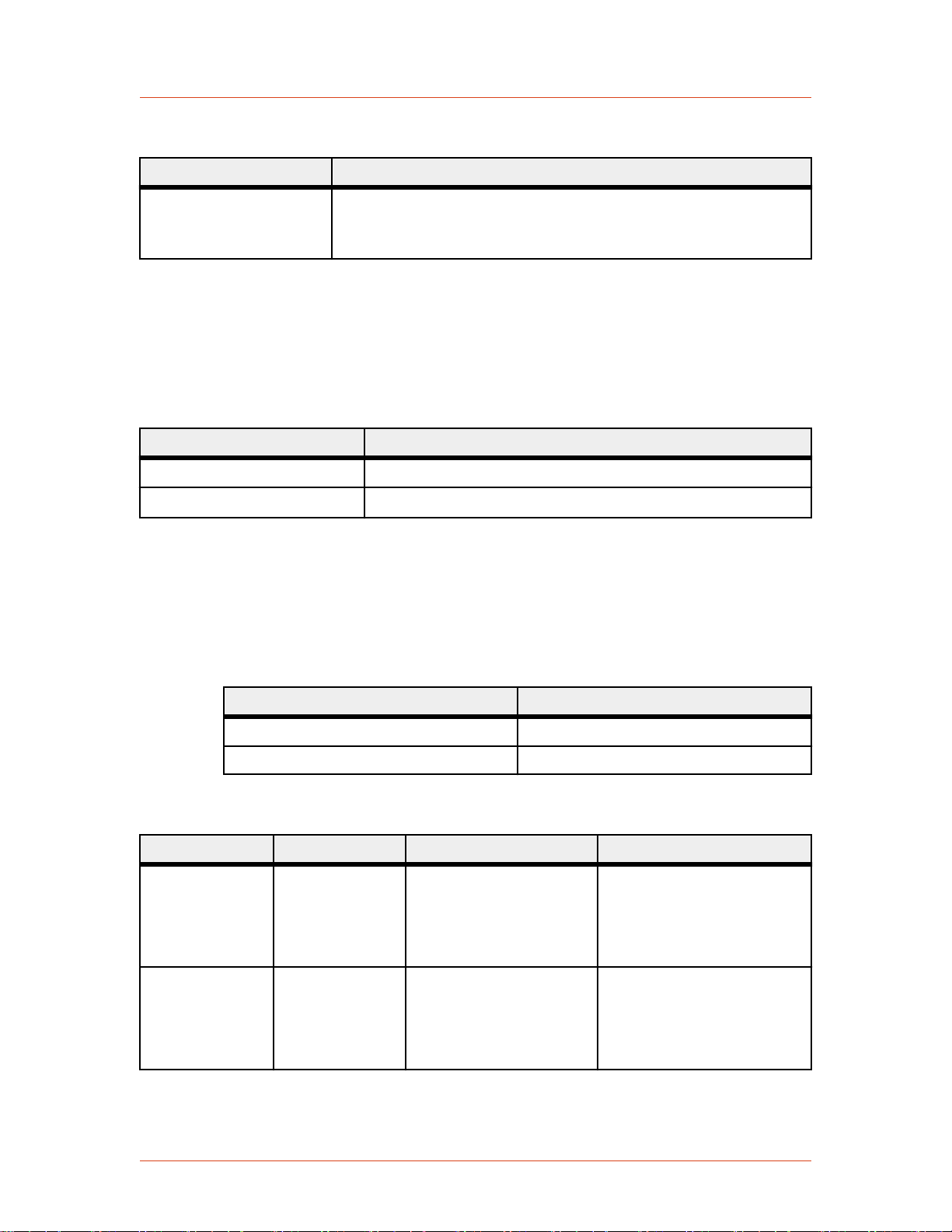
Delivered power into
mismatch
Varies by output power (see your unit's label for RF Power)
RF power Delivered power
300 W 33% of nominal power
500 W 30% of nominal power
600 W 33% of nominal power
1000 W 20% of nominal power
1200 W 16% of nominal power
Maximum reflected
power
Varies by power (see your unit's label for RF Power)
RF power Maximum reflected power
300 W 100 W
500 W 175 W
600 W, 1000 W, 1200 W 200 W
Load impedance 50 Ω
Harmonics At full rated output, all harmonics are 45 dB below the RF output
signal when operated into a 50 Ω, nonreactive load impedance. All
spurious (nonharmonic) outputs are 60 dB below the RF output
signal.
RF power regulation 1.0% of set point or 0.1% of full rated power, whichever is greater
RF power stability 1.0% of set point or 0.2% of full rated power, whichever is greater
RF pulse frequency
• 1 Hz to 10 kHz for units with RF Frequency of 2 MHz through
4 MHz
• 1 Hz to 30 kHz for units with RF Frequency of 13.56 MHz
through 60.0 MHz
RF pulse duty cycle 1% to 99%
CEX Specifications
CEX input signal
• TTL or Sine; 0 to + 19 dBm, 50 Ω for models 2710, 403, 405,
4010
• TTL for all other models
57023916-00B Specifications 3‑3
Advanced Energy
Table 3‑2. Electrical specifications (Continued)
Description Specification
CEX output signal
• Sine; 7 dBm ± 3dB, 50 Ω for models 2710, 403, 405, 4010
• TTL for all other models
COOLING SPECIFICATIONS
Table 3‑3. Air cooling specifications
Description Specification
Cooling medium Air
Minimum air flow
118 m3/h (69.45 cfm)
ENVIRONMENTAL SPECIFICATIONS
Table 3‑4. Environmental standard specifications
Description Specification
Overvoltage Category II
Pollution degree 2
Table 3‑5. Climatic specifications
Temperature Relative Humidity Air Pressure
Operating 5°C to +35°C
+41°F to +95°F
5% to 85%
+1 g/m3 to +25 g/m
note 1
78.8 kPa to 106 kPa
3
788 mbar to 1060 mbar
Equivalent altitude: 2000 m
to -500 m (6562′ to -1640′)
Storage -25°C to +55°C
-13°F to +131°F
5% to 95%
+1 g/m3 to +29 g/m
78.8 kPa to 106 kPa
3
788 mbar to 1060 mbar
Equivalent altitude: 2000 m
to -500 m (6562′ to -1640′)
3‑4 Specifications 57023916-00B
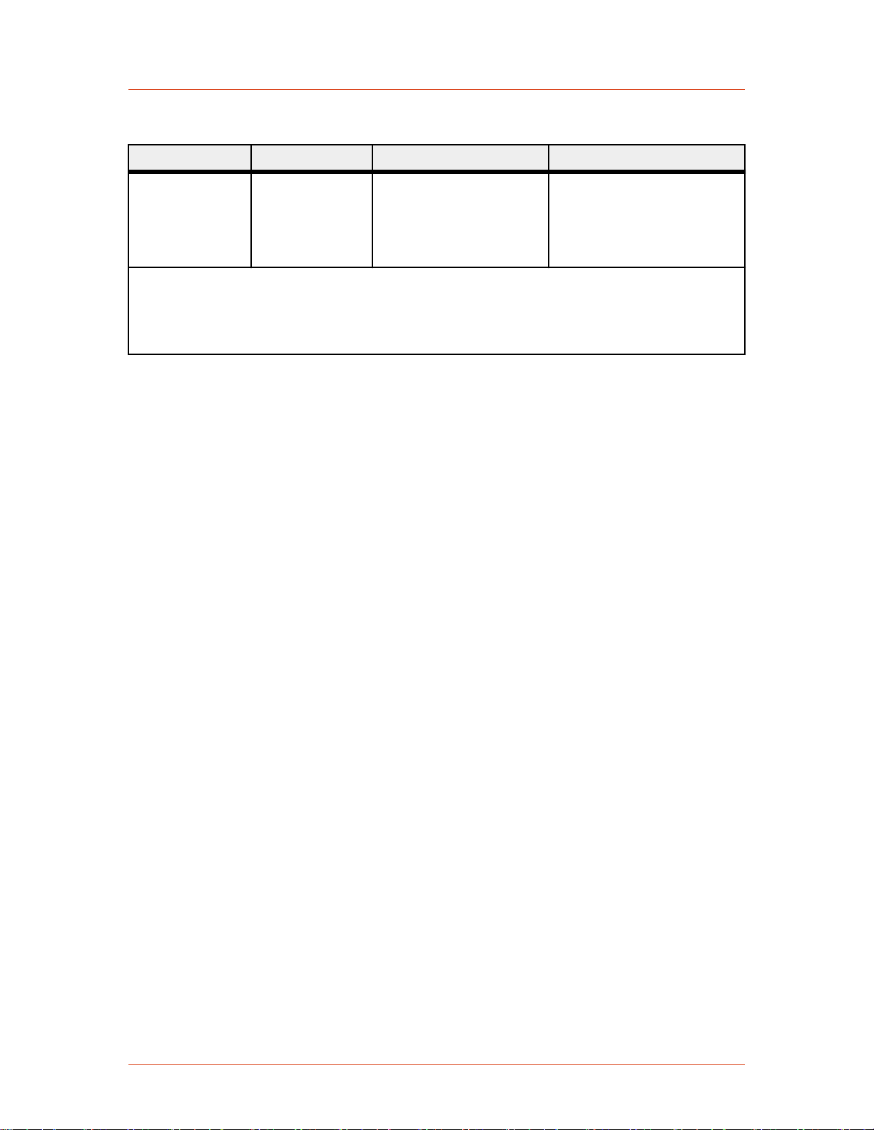
Table 3‑5. Climatic specifications (Continued)
Temperature Relative Humidity Air Pressure
Cesar® Generator
Transportation -25°C to +70°C
-13°F to +158°F
note 2
95%
+60 g/m3
note 3
65.6 kPa to 106 kPa
656 mbar to 1060 mbar
Equivalent altitude: 3500 m
to -500 m (11480′ to -1640′)
note 1
Non-condensing, no formation of ice
note 2
Maximum relative humidity when the unit temperature slowly increases, or when the unit
temperature directly increases from -25°C to +30°C
note 3
Maximum absolute humidity when the unit temperature directly decreases from +70°C to +15°C
57023916-00B Specifications 3‑5

Advanced Energy
3‑6 Specifications 57023916-00B

Pin 8 Pin 1
Pin 9
Pin 15
Cesar® Generator
Chapter
Communication Controls
DIAGNOSTIC INTERFACE
Each Cesar generator has a Diagnostic interface for use only at authorized service
centers. Technicians can check internal commands, calibrate the unit, or flash
software using this interface.
MATCHING INTERFACE
Each Cesar generator provides a Matching interface that allows full communication
between the Cesar generator and a VarioMatch or Navio matching network (or other
electrically and functionally compatible matching network).
4
☞ Important
This interface will not work with other matching networks unless they are
electrically and functionally compatible.
Matching Interface Connector
The Matching interface is a 15-pin, subminiature-D, female connector
Figure 4‑1. Matching interface connector
Matching Interface Pin Descriptions
Table 4‑1. Matching interface pin descriptions
Pin Name Signal
type
Level Description
1 GROUND Connect to the shield of
the cable (for example, RC
cable).
57023916-00B Communication Controls 4‑1

Advanced Energy
Table 4‑1. Matching interface pin descriptions (Continued)
Pin Name Signal
Level Description
type
2 DECREASE
C
Load
Digital
Output
Open collector
30 V capable
The output is connected to
ground to turn the Load
motor counter clockwise.
3 INCREASE
C
Load
Digital
Output
Open collector
30 V capable
The output is connected to
ground to turn the Load
motor clockwise.
4 DECREASE
C
Tune
Digital
Output
Open collector
30 V capable
The output is connected to
ground to turn the Tune
motor counter clockwise.
5 INCREASE
C
Tune
Digital
Output
Open collector
30 V capable
The output is connected to
ground to turn the Tune
motor clockwise.
6 MEASURE
GROUND
Reference ground for the
measurement of analog
signals at pins 12 to 14.
7 NO
CONNECTION
8 MANUAL TUNE Digital
Output
Open collector
30 V capable
To set the VarioMatch or
Navio matching network
to manual tune control,
connect this pin to ground.
To set the VarioMatch or
Navio matching network
to automatic tune control,
leave this pin
unconnected.
9 CASE GROUND Connect to the shield of
the cable.
10 NO
CONNECTION
11 STATUS Digital
Input
+15 V This pin connects the
+15 V output voltage of
the VarioMatch or Navio
matching network to
indicate if a match
network is connected.
4‑2 Communication Controls 57023916-00B

Cesar® Generator
Table 4‑1. Matching interface pin descriptions (Continued)
Pin Name Signal
12 DC BIAS
MEASURE
VOLTAGE
13 POSITION OF
TUNE
CAPACITOR
Analog
Input
Analog
Input
type
Level Description
0 V to 10 V This pin reads a test
voltage of the DC self bias
voltage. The scaling is
adjustable. For example,
in the default
configuration of the
VarioMatch or Navio
matching network, 4000 V
bias voltage is equal to
10 V test voltage and is
displayed on the front
panel as 4000.
0 V to 10 V The voltage at this input is
proportional to the
position of the Tune
capacitor. A 10 V reading
at this pin is equal to
100% on the front panel
display.
14 POSITION OF
LOAD
CAPACITOR
15 MATCH IS
ACTIVE
USER PORT
The User Port on the Cesar generator provides analog and digital signals for
controlling and monitoring the unit.
Analog
Input
Digital
Input
0 V to 10 V The voltage at this input is
proportional to the
position of the Load
capacitor. A 10 V reading
at this pin is equal to
100% on the front panel
display.
Pull up to 5 V This input is switched to
ground when the
VarioMatch or Navio
matching network is active
(motors are running) and it
floats when the matching
procedure is complete.
There are two User Port options available for the Cesar generator:
• A 25-pin User Port
57023916-00B Communication Controls 4‑3

Pin 1 Pin 13
Pin 14
Pin 25
Advanced Energy
• A 15-pin User Port
This section describes both User Port connectors, the minimal connections required
to operate the unit, cabling requirements, and detailed information about the User
Port signals.
Related Links
• “25-Pin User Port” on page 4-4
• “15-Pin User Port” on page 4-18
25-Pin User Port
USER PORT CONNECTOR
The User Port uses a 25-pin, shielded, female, subminiature-D connector.
Figure 4‑2. User Port connector, 25 Pin
SATISFYING MINIMAL REQUIREMENTS FOR THE 25-PIN USER PORT
If you do not use the User Port to control or monitor the Cesar generator, you still
must satisfy the User Port INTERLOCK LOOP signal to operate the generator.
WARNING:
Advanced Energy products only include interlocks when required by product
specification. Interlocks in Advanced Energy products are not intended to
meet or satisfy safety requirements. Where interlocks exist, you must still
meet and satisfy safety requirements. The presence of interlocks does not
imply operator protection.
The Cesar generator may be shipped with an interlock jumper plug that provides a
connection between the interlock pins. You can use this jumper plug to satisfy the
interlock and enable operation in situations where you do not intend to connect the
remaining pins on this port.
Units with an optional RF cover: In addition to the interlock jumper plug for the User
Port, your unit uses an RF / User Port interlock adapter cable.
4‑4 Communication Controls 57023916-00B
Using the interlock jumper plug disables the interlock function.

Cesar® Generator
Interlock does not switch the generator on/off. If an interlock is not satisfied, the
Cesar generator will issue an interlock error. Interlock errors must be resolved, so
you must switch RF off (via the User Port or host port) or resolve the error (via the
front panel) before you can switch on RF power again.
If you will be using the User Port, see pins 10 and 23 in the pin descriptions.
When the interlock is opened and then closed again, you must resolve the interlock
error before using the generator again. To resolve the error with the User Port, you
must switch RF power from on to off. For this reason, never physically connect the
RF POWER ON pin with INTERLOCK. If you do so you many not be able to switch
on the generator.
Your unit includes an RF/User port interlock adapter cable, which connects to the
unit’s RS-232 and the RF cover. You will use the RS-232 connector on the cable in
the same way as described in this section.
Your unit includes an RF cover. You must connect the unit’s RS-232 to the RF cover.
Related Links
RF/User Port Interlock (Units with Optional RF Cover)
• “To Connect Output Power” on page 5-6
25-PIN USER PORT CABLING REQUIREMENTS
The cable used to connect the generator’s User Port to the system controller must be
a shielded, 25-wire I/O cable.
Recommendations:
• Shielded twisted-pair wiring may be used but is not mandatory.
• Signal losses should be minimized by keeping the cable length as short as
possible. The maximum recommended cable length between the generator and
the controller is 10 meters (33´).
• Signals at the User Port can be sensitive to environmental noise. Take standard
preventive measures against electro-magnetic interference (EMI), including
using shielded cabling to prevent errors from being induced into the User Port.
• Grounding the User Port at the power supply reduces noise interference. To
avoid ground loop problems, you should typically ground only one end of the
cable.
ACTIVATING THE 25-PIN USER PORT
The Cesar generator can run in front panel control mode, User Port remote control
mode, or host port remote control mode. You can activate the User Port remote
control mode using either of the following methods:
• The front panel
57023916-00B Communication Controls 4‑5

Advanced Energy
• Host port command 14
If User Port remote control is activated, it remains active even if the generator is
switched off and on. You can deactivate User Port remote control via either the front
panel or host port command 14.
RESOLVING ERROR DISPLAYS WHEN USING THE 25-PIN USER PORT
If the Cesar generator encounters an error while being operated via the User Port, the
generator displays the error message on the front panel display and turns off RF
power. The Cesar generator continues to show the error message on the front panel
until both of the following conditions are met:
WARNING:
RISK OF DEATH OR BODILY INJURY. The Cesar unit will deliver RF power
immediately at system power up when all of the following conditions are met:
User port is activated; pin 4 (
(
INTERLOCK LOOP
) is activated.
RF POWER ON
) is activated; and pin 10
• The error condition is gone
• The RF on signal is deactivated
Once the above two conditions are met, the error message is deleted and the Cesar
generator shows the normal display.
25-PIN USER PORT PIN DESCRIPTIONS AND WIRING DIAGRAMS
User Port Signal Specifications
Unless otherwise specified, all analog signals are 0 V to 10 V while all digital signals
are 5 V or V
Interface
.
4‑6 Communication Controls 57023916-00B

Cesar® Generator
Table 4‑2. User Port Signal Specifications
Signal Type Description
Analog Inputs By default, the User Port set point and DC bias input signals
(pins 5 and 7) are scaled 0 V to 10 V (physically limited to 10 V).
These signals are scalable from 0 V to 2 V up to 0 V to 20 V
(physically limited to 10 V) in increments of 0.5 V. You can set
the scaling through the RS-232 port or the PROFIBUS port (host
port command 30) or through the front panel menu commands.
☞ Important
Using lower input voltages decreases resolution.
☞ Important
Use a range of 0 V to 20 V only for special purposes such
as cable attenuation.
Analog
Outputs
By default, the User Port analog output signals (pins 2 and 3) are
scaled 0 V to 10 V (physically limited to 10 V). These signals are
scalable from 0 V to 2 V up to 0 V to 20 V (physically limited to
10 V) in increments of 0.5 V. You can set the scaling through the
RS-232 port or the PROFIBUS port (host port command 30) or
through the front panel menu commands.
☞ Important
Using lower input voltages decreases resolution.
☞ Important
Use a range of 0 V to 20 V only for special purposes such
as cable attenuation.
These signals are driven by operational amplifiers capable of
driving high-capacitance loads such as those expected in shielded
interface applications. The user’s receiver must present a 10 kΩ
(or higher) impedance to these signals. The readback signals
represent the forward and reflected power as measured at the
output of the generator.
Digital Inputs Pins 4, 6, 8, and 10 are opto-coupled. The user’s signal drives the
LED in the opto-coupler through a 4.7 kΩ resistor. A signal level
of 4 V to 30 V applied to the input pin activates the signal.
Digital Outputs The status signals provided by the generator (pins 12, 14, 22, and
24) are opto-coupled with NPN transistor outputs. The collector
and emitter of each transistor are provided to the user interface.
Each transistor can provide a maximum of 8 mA of collector
current and may be operated with a collector-to-emitter voltage of
up to 30 V.
Pulse Input The pulse input (pin 25) is a high-speed opto-coupled input. The
user’s signal drives the LED in the opto-coupler through a 1.2 kΩ
resistor. A signal level of 0 V to 1 V corresponds to low and 4 V
to 20 V corresponds to high.
57023916-00B Communication Controls 4‑7

Advanced Energy
Table 4‑2. User Port Signal Specifications (Continued)
Signal Type Description
Interlock The interlock signal (pins 10 and 23) enables the RF power
generation. Pin 10 is tied to the generator’s +15 V supply.
Connecting pin 10 to pin 23 closes the loop, enabling RF power.
User Port Pin Descriptions
This table provides the connector pin descriptions for the 25-pin User Port.
Table 4‑3. 25-Pin User Port Pin Descriptions
Signal
Pin
Return
Pin
Name Signal
Type
1 Return for pin 14 See pin 14
2 15 REFLECTED
POWER
Analog
output
MONITOR
Description
This signal provides a linearly scaled
read back of reflected power as measured
at the generator output.
The default range is 0 V to 10 V, but you
can change this range.
Default setting: 0 V to 10 V = 0 W to
maximum rated power output
Units with 0 V to 5 V scaling only: The
default range is 0 V to 5 V. Default
setting: 0 V to 5 V = 0 W to 1000 W. To
see if your unit has 0 V to 5 V scaling,
see “Products Documented in this
Manual” on page 1-1.
Pin 15 must be grounded.
3 16 FORWARD/
LOAD POWER
MONITOR
Analog
output
This signal provides a linearly scaled
read back of forward power or real
power (sometimes called load power) as
measured at the generator output. To
change control settings, see pin 8.
The default range is 0 V to 10 V, but you
can change this range.
Default setting: 0 V to 10 V = 0 W to
maximum rated power output.
Units with 0 V to 5 V scaling only: The
default range is 0 V to 5 V. Default
setting: 0 V to 5 V = 0 W to 1000 W. To
see if your unit has 0 V to 5 V scaling,
see “Products Documented in this
Manual” on page 1-1.
Pin 16 must be grounded.
4‑8 Communication Controls 57023916-00B

Table 4‑3. 25-Pin User Port Pin Descriptions (Continued)
Signal
Pin
Return
Pin
Name Signal
Type
Cesar® Generator
Description
4 17 RF POWER ON Digital
input
5 18 SET POINT Analog
input
This signal enables or disables RF
output. To enable RF output, apply a
positive voltage of 4 V to 30 V to this
pin. To disable RF output, apply a
voltage of 1.5 V or less to this pin
☞ Important
The interlocks must be satisfied
and the setpoint must be within
the output power range before
unit will deliver power.
Pin 17 must be grounded.
This signal sets the RF output set point.
Depending on the regulation mode, the
set point refers to forward power, real
power, or DC Bias regulation. The
default range is 0 V to 10 V, but you can
change this range.
A 0 V to 10 V signal applied to this pin
linearly controls the set point of the
generator.
Default setting: 0 V to 10 V = 0 W to
maximum rated power output
6 19 RF FORWARD
POWER/ DC
BIAS
REGULATION
Digital
input
For DC bias regulation, the scaling of the
set point must be the same as for the DC
bias signal (see pin 7).
Use this signal to select DC bias or
forward power regulation mode. To
regulate on DC bias input, apply a
positive voltage of 4 V to 30 V to this
pin. To regulate on forward or real
power, apply a voltage of 1.5 V or less or
an open connection.
See pin 8 for switching between forward
and real power regulation.
57023916-00B Communication Controls 4‑9

Advanced Energy
Table 4‑3. 25-Pin User Port Pin Descriptions (Continued)
Signal
Pin
Return
Pin
Name Signal
Type
Description
7 20 DC BIAS INPUT Analog
input
If your unit uses DC Bias Out, see the
next row.This input signal is used for DC
bias regulation, where the set point is
given by pin 5 (scaling must be the
same). The signal closes the control loop
around external components in the RF
path. The default range is 0 V to 10 V,
but you can change this range.
Default setting: 0 V to 10 V = 0 V to
4000 V
Units with 0 V to 5 V scaling only: The
default setting: 0 V to 10 V = 0 V to
3333 V. To see if your unit has 0 V to
5 V scaling, see “Products Documented
in this Manual” on page 1-1.
Typically, matching networks provide a
DC bias voltage monitor signal. When
this scaled representation of the DC bias
voltage is used for DC bias regulation
(see pin 6), the scaling must be the same
as for the set point (see pin 5).
VarioMatch and Navio matching
networks provide a DC bias voltage
monitor signal for regulation through the
Matching interface.
7 20 DC BIAS
OUTPUT
Analog
output
(If your unit uses DC Bias Out. All other
part numbers see previous row. See
“Products Documented in this Manual”
on page 1-1 to see if your unit uses DC
Bias Out.) This signal provides a linearly
scaled readback of DC Bias voltage as
measured at the matching network. The
default range is 0 V to 10 V, but you can
change this range.
Default setting: 0 V to 10 V = 0 V to
4000 V
Pin 20 must be grounded.
4‑10 Communication Controls 57023916-00B
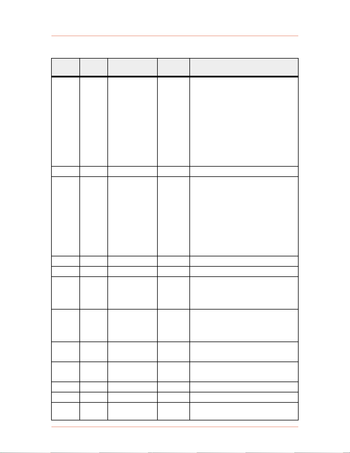
Table 4‑3. 25-Pin User Port Pin Descriptions (Continued)
Signal
Pin
Return
Pin
Name Signal
Type
Cesar® Generator
Description
8 21 RF FORWARD/
LOAD POWER
REGULATION
Digital
input
Use this signal to select between RF
forward power or real power (sometimes
called load power) regulation. Apply a
positive DC voltage between 4 V and
30 V to regulate on real power. An open
connection to pin 8 or a DC input voltage
of less than 1.5 V causes forward power
regulation.
Real power is defined as forward power
minus reflected power.
Pin 6 also changes the regulation mode.
9 Return for pin 22 See pin 22.
10 23 INTERLOCK
LOOP
Digital
input
To satisfy the interlock and enable RF
power in the generator, close an external
loop from pin 23 to pin 10. A resistance
of 15 Ω or less across this pin closes the
loop. Pin 23 feeds this loop via a current
limiting circuit (maximum 120 mA).
Alternatively, you can satisfy the
interlock by applying a voltage of +4 V
to +30 V (referenced to ground) to pin
10.
11 Return for pin 24 See pin 24.
12 RESERVED
13 21 +15 VDC
SUPPLY
Supply A nominal +15 VDC output referenced
to chassis ground, auxiliary supply for
external use (50 mA maximum); no
internal limit.
14 1 SET POINT
STATUS
Digital
output
When the generator is out of set point, a
low (opto-coupler output) impedance is
created between this pin and pin 1 (8 mA
maximum).
15 Return for pin 2 See pin 2.
Pin 15 must be grounded at the host.
16 Return for pin 3 See pin 3.
Pin 16 must be grounded at the host.
17 Return for pin 4 See pin 4.
18 Return for pin 5 See pin 5.
19 N/A DC GROUND Chassis
ground
DC ground connection common to
chassis ground.
57023916-00B Communication Controls 4‑11
Advanced Energy
Table 4‑3. 25-Pin User Port Pin Descriptions (Continued)
Signal
Pin
Return
Pin
Name Signal
Type
20 Return for pin 7 See pin 7.
Description
21 N/A CHASSIS
GROUND
22 9 OVERTEMP Digital
Chassis
ground
output
DC ground connection common to
chassis ground.
When an internal overtemperature
shutdown condition is detected, a low
(opto-coupler output) impedance is
created between this pin and pin 9 (8 mA
maximum).
The overtemperature condition can occur
in the RF driver, SMPS, or final
amplifier.
23 10 Return for pin 10 See pin 10.
24 11 INTERLOCK
SATISFIED
Digital
output
When the interlock is satisfied, a low
(opto-coupler output) impedance is
created between this pin and return pin
11 (8 mA maximum).
25 19 BLANKING/
PULSING
Pulse input When the unit is set for external pulsing,
this pin allows you to pulse (blank) the
RF power. Set the required logic for RF
on and off through the front panel menu.
When the unit is set for internal pulsing,
this pin allows you to switch between
internal pulsing and continuous wave
operation. Select the appropriate function
and signal level in the Pulse Settings
selection in the front panel menu.
Wiring Diagrams for the 25-Pin User Port
The diagrams in this section provide wiring information to connect to the 25-pin
User Port.
4‑12 Communication Controls 57023916-00B

_
+
2
15
1 nF
1 nF
+15 V
+15 V
10 k
220 220
10 k
10 nF
10 k
10 k
Voltage Measurement Device
(see pin description
for scaling)
Pin 15 must be grounded
Figure 4‑3. REFLECTED POWER MONITOR (pins 2 and 15)
2407
_
+
3
16
1 nF
1 nF
+15 V
+15 V
10 k
220 220
10 k
10 nF
10 k
10 k
Voltage Measurement Device
(see pin description
for scaling)
Pin 16 must be grounded
2408
4
17
1 nF
+4 V to +30 V
4 k7
Cesar® Generator
Figure 4‑4. FORWARD/LOAD POWER MONITOR (pins 3 and 16)
Figure 4‑5. RF POWER ON signal wiring (pins 4 and 17)
57023916-00B Communication Controls 4‑13

2411
_
+
+15 V
+15 V
18
5
100 k
+
_
10 k
10 k
1 nF
1 nF
See pin description for scaling
2409
6
19
1 nF
+4 V to +30 V
4 k7
2412
_
+
+15 V
+15 V
20
7
100 k
10 k
10 k
In
In
1 nF
1 nF
User-defined feedback
Advanced Energy
Figure 4‑6. SET POINT signal wiring (pins 5 and 18)
Figure 4‑7. RF FORWARD POWER/DC BIAS REGULATION wiring (pins 6 and 19)
Figure 4‑8. DC BIAS MONITOR signal wiring (pins 7 and 20) (units with DC Bias In)
4‑14 Communication Controls 57023916-00B

3647
_
+
7
20
1 nF
1 nF
+15 V
+15 V
10 k
220 220
10 k
10 nF
10 k
10 k
Voltage Measurement Device
(see pin description
for scaling)
Pin 20 must be grounded
2410
8
21
1 nF
+4 V to +30 V
4 k7
Cesar® Generator
Figure 4‑9. DC BIAS MONITOR signal wiring (pins 7 and 20) (units with DC Bias
Out)
Figure 4‑10. RF FORWARD/LOAD REGULATION signal wiring (pins 8 and 21)
57023916-00B Communication Controls 4‑15

2413
+15 V
23
10
120 mA
1 nF
4 k7
+4 V to +30 V
Interlock
Interlock Return
(alternatively)
1838
+15 V
13
21
+15 V provided to user
Advanced Energy
Figure 4‑11. INTERLOCK LOOP signal wiring (pins 10 and 23)
Figure 4‑12. +15 VOLT DC signal wiring (pins 13 and 21)
4‑16 Communication Controls 57023916-00B
2415
14
1
1 nF
+ 30 V Maximum
Figure 4‑13. SET POINT STATUS signal wiring (pins 14 and 1)
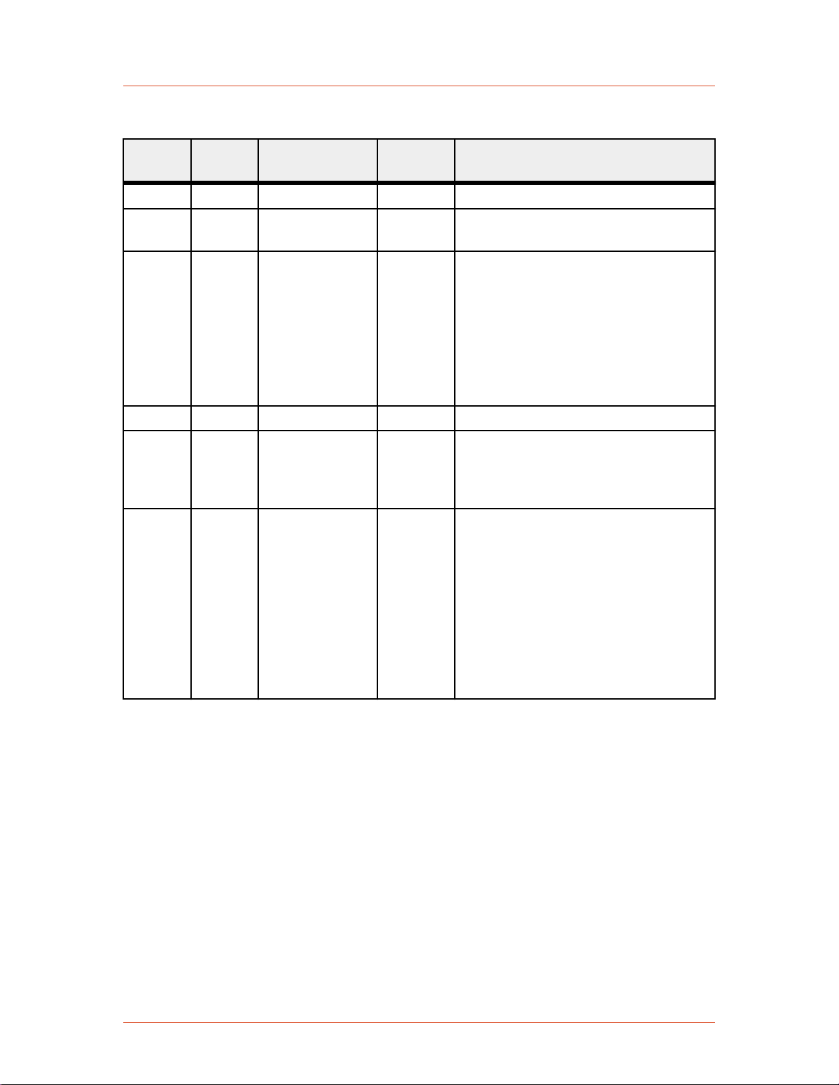
22
9
1 nF
+ 30 V Maximum
2417
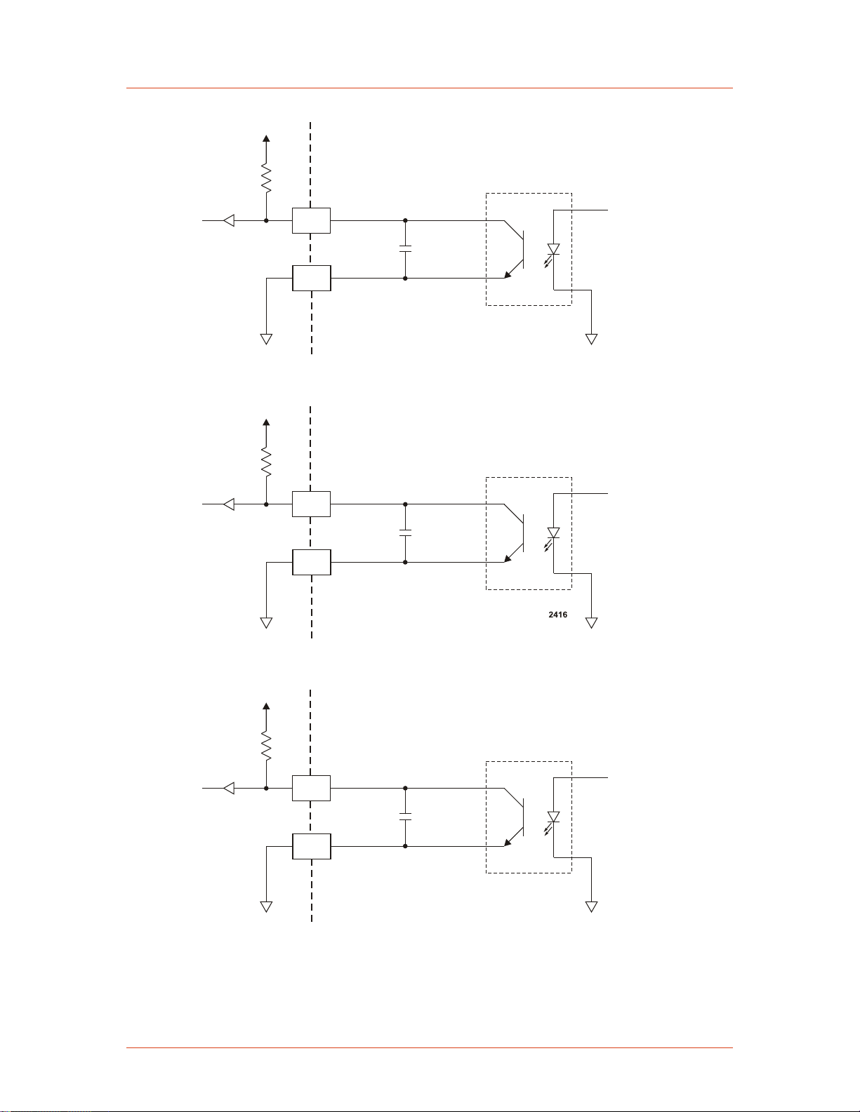
24
11
1 nF
+ 30 V Maximum
Cesar® Generator
Figure 4‑14. OVERTEMPERATURE signal wiring (pins 22 and 9)
Figure 4‑15. INTERLOCK SATISFIED signal wiring (pins 24 and 11)
57023916-00B Communication Controls 4‑17

2418
25
19
1 nF
1 k2 1 k2
1 k2 1 k2
+5 V
In
Out
Gnd
0 to 1 V (low)
4 to 20 V (high)
Pin 8
Pin 1
Pin 9
Pin 15
Advanced Energy
Figure 4‑16. BLANKING/PULSING signal wiring (pins 25 and 19)
15-Pin User Port
USER PORT CONNECTOR
The User Port uses a 15-pin, shielded, male, subminiature-D connector that connects
the generator with an external remote control unit.
Figure 4‑17. User Port connector, 15 Pin
SATISFYING MINIMAL REQUIREMENTS FOR THE 15-PIN USER PORT
Each Cesar generator with a 15-pin User Port also has an Interlock interface that
allows you to integrate any Cesar generator into a system interlock loop that
interrupts delivered RF power.
WARNING:
Advanced Energy products only include interlocks when required by product
specification. Interlocks in Advanced Energy products are not intended to
meet or satisfy safety requirements. Where interlocks exist, you must still
meet and satisfy safety requirements. The presence of interlocks does not
imply operator protection.
Even if you do not connect the Cesar generator into a larger system interlock loop,
you must make the proper connections for the unit to enable RF power.
4‑18 Communication Controls 57023916-00B

Pin 1
Cesar® Generator
The Cesar generator may be shipped with an interlock jumper plug that provides a
connection between the interlock pins (pins 1 and 2). You can use this jumper plug to
satisfy the interlock and enable operation in situations where you do not intend to
connect the remaining pins on this port.
☞ Important
Using the interlock jumper plug disables the interlock function
☞ Important
Interlock does not switch the generator on/off. If an interlock is not satisfied,
the Cesar generator will issue an interlock error. Interlock errors must be
resolved, so you must switch RF off (via the User Port or host port) or resolve
the error (via the front panel) before you can switch on RF power again.
When the interlock is opened and then closed again, you must resolve the interlock
error before using the generator again. To resolve the error with the User Port, you
must switch RF power from on to off. For this reason, never physically connect the
RF POWER ON pin with INTERLOCK. If you do so you many not be able to switch
on the generator.
Interlock Interface Connector
The Interlock interface is a 9-pin connector.
Figure 4‑18. Interlock interface connector
Interlock Interface Pin Descriptions
Pins not described in the table are reserved.
Pin Name Reference
pin
1 INTERLOCK
INPUT (+)
3 Input
Signal type Level Description
(floating)
5 V
to
24 V
Contact closure to
pin 2 via an external
interlock loop. You
may also provide a
5 VDC to 24 VDC
signal referenced to
pin 3 to satisfy the
interlock
2 INTERLOCK
OUTPUT
57023916-00B Communication Controls 4‑19
3 Output
(floating)
15 V Contact closure to
pin 1 via the user’s
external interlock
loop. This voltage
output is floating and
has no reference to
ground.

Advanced Energy
Pin Name Reference
Signal type Level Description
pin
3 INTERLOCK
RETURN (-)
floating 0 V This is the return pin
for an external
interlock signal. This
pin must be used as
return for the
external interlock
voltage, because the
interlock input (pin
1) is floating and has
no reference to
ground.
4 Connect to the shield
of the external
interlock cable.
15-PIN USER PORT CABLING REQUIREMENTS
The cable used to connect the generator’s User Port to the system controller must be
a shielded, 15-wire I/O cable.
Recommendations:
• Shielded twisted-pair wiring may be used but is not mandatory.
• Signal losses should be minimized by keeping the cable length as short as
possible. The maximum recommended cable length between the generator and
the controller is 10 meters (33´).
• Signals at the User Port can be sensitive to environmental noise. Take standard
preventive measures against electro-magnetic interference (EMI), including
using shielded cabling to prevent errors from being induced into the User Port.
• Grounding the User Port at the power supply reduces noise interference. To
avoid ground loop problems, you should typically ground only one end of the
cable.
ACTIVATING THE 15-PIN USER PORT
The Cesar generator can run in front panel control mode, User Port remote control
mode, or host port remote control mode. You can activate the User Port remote
control mode using either of the following methods:
• The front panel
• Host port command 14
4‑20 Communication Controls 57023916-00B

Cesar® Generator
If User Port remote control is activated, it remains active even if the generator is
switched off and on. You can deactivate User Port remote control via either the front
panel or host port command 14.
WARNING:
RISK OF DEATH OR BODILY INJURY. The Cesar unit will deliver RF power
immediately at system power up when all of the following conditions are met:
User port is activated; pin 10 (
and pin 1 (
INTERLOCK INPUT
RF POWER ON
) of the Interlock interface is activated.
) of the User port is activated;
RESOLVING ERROR DISPLAYS WHEN USING THE 15-PIN USER PORT
If the Cesar generator encounters an error while being operated via the User Port, the
generator displays the error message on the front panel display and turns off RF
power. The Cesar generator continues to show the error message on the front panel
until both of the following conditions are met:
• The error condition is gone
• The RF on signal is deactivated
Once the above two conditions are met, the error message is deleted and the Cesar
generator shows the normal display.
15-PIN USER PORT PIN DESCRIPTIONS AND WIRING DIAGRAMS
This table provides the connector pin descriptions for the 15-pin User Port. For a
description of the signal types, see “User Port Signal Specifications” on page 4-6
Table 4‑4. 15-Pin User Port Pin Descriptions
Signal
Pin
1 8 OPERATING
Return
Pin
Name Signal
MODE A
Type
Digital
input
Description
Connecting pin 1 and pin 2 to a high or
low level allows you to set the regulation
mode as indicated in Table 4-5 on
page 4-24.
A high level switches to remote control.
2 8 OPERATING
MODE B
Digital
input
Connecting pin 1 and pin 2 to a high or
low level allows you to set the regulation
mode as indicated in Table 4-5 on
page 4-24.
A high level switches to remote control.
57023916-00B Communication Controls 4‑21

Advanced Energy
Table 4‑4. 15-Pin User Port Pin Descriptions (Continued)
Signal
Pin
Return
Pin
Name Signal
Type
Description
3 8 READY STATUS Digital
output
4 8 ERROR Digital
output
5 8 MAXIMUM RF
POWER LEVEL
Digital
output
REACHED
This signal indicates that the generator is
ready for operation.
This signal indicates an error such as
overload due to temperature, mismatch,
or an open interlock loop.
This error message indicates that more
RF power is demanded than available by
the RF generator. This error may occur
in the following situations:
• In DC Bias regulation mode, the RF
power necessary for the desired DC
Bias voltage may be higher than the
generator is able to deliver.
• In real power regulation mode, the
forward power necessary may be
higher than the generator is able to
deliver.
• The external pulsing frequency
exceeds the limit. (See the
specifications.)
6 8 RF ON Digital
output
This signal indicates that more than 1%
of the nominal power is present at the RF
output.
7 8 INTERFACE
VOLTAGE
Digital
input
If no voltage is applied to pin 7, 5 V is
the standard level for digital inputs and
outputs. If you want any other level, an
external voltage must be applied to pin 7
and will be used as supply voltage for the
digital outputs at pin 3, 4, 5, and 6.
The voltage range is 5 V to 24 V, with a
maximum current of 300 mA, depending
on the load at the outputs.
8 GROUND Reference pin.
4‑22 Communication Controls 57023916-00B

Table 4‑4. 15-Pin User Port Pin Descriptions (Continued)
Signal
Pin
Return
Pin
Name Signal
Type
Cesar® Generator
Description
9 8 BLANKING/
PULSE MODE
10 8 RF POWER ON Digital
11 8 DC BIAS SET
POINT
TTL Input Pulse signal input. A TTL square wave
input
Analog
input
input that allows RF power blanking.
Use this input if the internal pulsing
capabilities do not meet your
requirements.
When external pulsing is not used, this
input may be set up to switch between
continuous wave operation and internal
pulsing. This alternate function is
enabled by changing the unit setting
(Device Configuration Settings from
the front panel)
This signal allows you to enable or
disable RF power.
☞ Important
Before the generator can deliver
power, the interlock must be
satisfied.
This signal provides a linearly scaled
setting to the DC bias voltage. The
default range is 0 V to 10 V, but you can
change this range.
12 8 RF POWER SET
POINT
13 8 TEST VOLTAGE
FOR FORWARD
POWER
Analog
input
Analog
output
0 V to 10 V = 0 V to maximum DC bias
(4000 V default maximum value).
This signal provides a linearly scaled
setting to the RF forward power. The
default range is 0 V to 10 V, but you can
change this range.
For example, 5 V = 50% of the nominal
generator power; 10 V = 100%.
This signal provides a linearly scaled
readback of RF forward power as
measured at the generator output. The
default range is 0 V to 10 V, but you can
change this range.
0 V to 10 V = 0 W to maximum output
power.
57023916-00B Communication Controls 4‑23

Advanced Energy
Table 4‑4. 15-Pin User Port Pin Descriptions (Continued)
Signal
Pin
Return
Pin
Name Signal
Type
Description
14 8 TEST VOLTAGE
FOR
REFLECTED
POWER
15 8 TEST VOLTAGE
FOR DC SELF
BIAS
Table 4‑5. Setting regulation mode with 15-pin User Port pins 1 and 2
Operating
Mode A
(Pin 1)
Low Low Local No remote control function
Operating
Mode B
(Pin 2)
Analog
output
Analog
output
Control
Setting
This signal provides a linearly scaled
setting to reflected power as measured at
the generator output. The default range is
0 V to 10 V, but you can change this
range.
For example, 5 V = 50% of the nominal
generator power; 10 V = 100%.
This signal provides a linearly scaled
setting to DC self bias voltage as
measured at the matching network. The
default range is 0 V to 10 V, but you can
change this range.
For example, 5 V = 50% of the nominal
DC bias (4 kV); 10 V = 100%.
Description
Low High Remote RF forward power
High Low Remote DC Bias regulation
High High Remote Real power
Wiring Diagrams for the 15-Pin User Port
The diagrams in this section provide wiring information to connect to the 15-pin
User Port.
4‑24 Communication Controls 57023916-00B

2332
_
+
+6 V
8
7
100 nF
+
_
3.9 k
11
5.6 k
10 k
10 nF
10 k
+15 V
33 V
5-24 V
Supplied
Figure 4‑19. OPERATING MODE A wiring diagram (pins 1 and 8)
2333
_
+
+15 V
8
7
100 nF
5-24 V
+
_
3.9 k
2
5.6 k
10 k
10 nF
10 k
+6 V
33 V
Supplied
Cesar® Generator
Figure 4‑20. OPEATING MODE B wiring diagram (pins 2 and 8)
57023916-00B Communication Controls 4‑25

2335
3.9 k
M
8
3
1.5 k
10 k
10 nF
1.5 k
50 mA
+5 V (or V at pin 7)
2336
3.9 k
M
8
4
1.5 k
10 k
10 nF
1.5 k
50 mA
+5 V (or V at pin 7)
Advanced Energy
Figure 4‑21. READY STATUS wiring diagram (pins 3 and 8)
Figure 4‑22. ERROR wiring diagram (pins 4 and 8)
4‑26 Communication Controls 57023916-00B

2337
3.9 k
M
8
5
1.5 k
10 k
10 nF
1.5 k
50 mA
+5 V (or V at pin 7)
2338
3.9 k
M
8
6
1.5 k
10 k
10 nF
50 mA
1.5 k
+5 V (or V at pin 7)
Cesar® Generator
Figure 4‑23. MAXIMUM POWER LEVEL REACHED wiring diagram (pins 5 and 8)
Figure 4‑24. RF ON wiring diagram (pins 6 and 8)
57023916-00B Communication Controls 4‑27

2339
+15 V
7
5-24 V
+
_
8
100 nF
V
in
V
out
100 nF
330 W
1.5 k
+V
supply
100 nF
+6 V
33 V
External Supply
Adj
2343
9
8
5 V TTL
2.2 k
10 k
4.7 V
Advanced Energy
Figure 4‑25. INTERFACE VOLTAGE wiring diagram (pins 7 and 8)
Figure 4‑26. BLANKING/PULSING MODE wiring diagram (pins 9 and 8)
4‑28 Communication Controls 57023916-00B

2334
_
+
+15 V
8
7
100 nF
5-24 V
+
_
3.9 k
10
5.6 k
10 k
10 nF
10 k
+6 V
33 V
Supplied
Figure 4‑27. RF POWER ON wiring diagram (pins 10 and 8)
2340
_
+
+14 V
8
0-10 V
11
22 k
1 nF
2392
_
+
+14 V
8
0-10 V
12
22 k
1 nF
Cesar® Generator
Figure 4‑28. DC BIAS SET POINT wiring diagram (pins 11 and 8)
Figure 4‑29. RF POWER SET POINT wiring diagram (pins 12 and 8)
57023916-00B Communication Controls 4‑29

2341
_
+
+14 V
8
0-10 V=
0-100%
13
M
470 R
22 k
1 nF
25 V
2342
_
+
+14 V
8
0-10 V=
0-100%
14
M
470 R
22 k
1 nF
25 V
Advanced Energy
Figure 4‑30. TEST VOLTAGE FOWARD POWER wiring diagram (pins 13 and 8)
Figure 4‑31. TEST VOLTAGE REFLECTED POWER wiring diagram (pins 14 and
8)
4‑30 Communication Controls 57023916-00B

2393
_
+
+14 V
8
0-10 V=
0-100%
15
M
470 R
22 k
1 nF
25 V
Figure 4‑32. TEST VOLTAGE FOR DC BIAS wiring diagram (pins 15 and 8)
CESAR GENERATOR HOST PORT
Cesar® Generator
The Cesar generator has three communications (host port) interface options that
allow the generator to interface with a host computer:
• RS-232 With AE Bus
• PROFIBUS
• Ethernet (Modbus/TCP)
To determine which host port option you have, refer to the labels on your unit.
The host port commands are very similar for all interfaces. All host port commands
are listed and described in the host port commands table.
Related Links
• “RS-232 Interface” on page 4-31
• “PROFIBUS Interface” on page 4-37
• “Ethernet Interface” on page 4-44
• “AE Bus Commands” on page 4-50
RS-232 Interface
The Cesar unit provides a serial communications interface through the RS-232 port.
This interface allows the Cesar unit to interface with a host computer using the AE
Bus protocol.
The RS-232 AE Bus host port interface uses an RS-232 signal format and AE Bus
communication protocol.
57023916-00B Communication Controls 4‑31

Pin 1
Advanced Energy
Installations that require a long cable or are located in an environment with high
electrical noise may experience intermittent communications errors. If you
experience intermittent communications errors, AE recommends adding an optocoupler plug between the RS-232 AE Bus host port and cable connector. Contact AE
Global Services to purchase an opto-coupler for your unit.
RS-232 CONNECTOR
The serial RS-232 port connector is a 9-pin, female, shielded, subminiature-D
connector for interfacing with a host computer.
Figure 4‑33. RS-232 port connector
RS-232 PORT PIN DESCRIPTIONS
Table 4‑6. RS-232 port pin descriptions
Signal
Name Description
Pin
1 RESERVED Reserved for future use
2 tx RS232 RS-232 transmit data
3 rx RS232 RS-232 receive data
4 RESERVED Reserved for future use
5 COM Data common
6 RESERVED Reserved for future use
7 RESERVED Reserved for future use
8 RESERVED Reserved for future use
*
9
*
Do not connect pins marked RESERVED. Do not ground this factory
RESERVED (FACTORY) Reserved for future use
reserved pin. Grounding this pin disrupts the operation of the unit.
AE BUS TRANSMISSION PARAMETERS
The communications capability of the RS-232 port is limited to the following
parameters:
• RS-232 protocol
• Baud rates, selected on the front panel:
◦ 9600
4‑32 Communication Controls 57023916-00B

Cesar® Generator
◦ 19,200
◦ 38,400
◦ 57,600
◦ 115,200
• Cesar unit address is always 1.
• Odd parity
• One start bit, eight data bits, one stop bit
• Low-order bytes transmitted before high-order bytes (little endian)
The host computer must finish one transaction with the Cesar unit before it initiates
another one, either with the same unit or any other unit.
The Cesar unit sends data through pin 2 (TX RS232). This pin must be connected to
the receive pin (RX RS232) on the host computer’s serial connector. The receive pin
is normally pin 2 for a standard, 9-pin serial port.
AE BUS PROTOCOL
The AE Bus protocol uses pure binary data (nothing is coded in ASCII) and is
designed to facilitate direct communications between a host computer and the Cesar
unit. The AE Bus message packet combines a set quantity of bits and bytes in such a
way that groups of information can be sent over communications lines at one time.
Five types of information (fields) make up a communications message packet.
• Header (address and the length of Data field)
• Command Number
• Optional Length byte
• Data
• Checksum
57023916-00B Communication Controls 4‑33
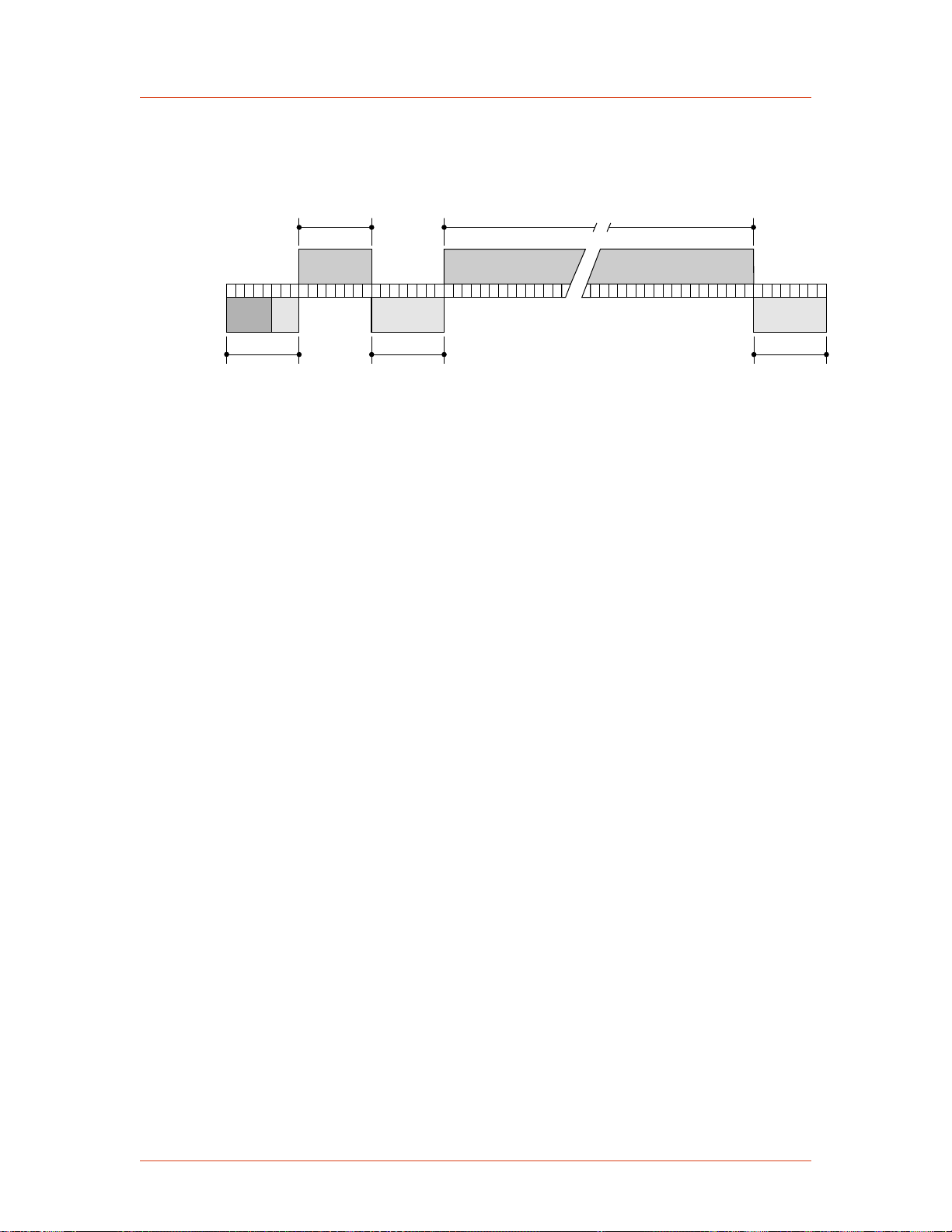
2
2
7 6 5 4 3 2 1 0 7 6 5 4 3 2 1 0 7 6 5 4 3 2 1 0 7 6 5 4 3 2 1 0 7 6 5 4 3 2 1 07 6 5 4 3 2 1 07 6 5 4 3 2 1 01 07 6 5 4 3
Data (0-255 bytes)
Command Number
0-255
Header
5-bit address
3-bit length
Optional Length Byte Checksum
1138
Advanced Energy
Figure 4-34 shows the organization of these fields in the AE Bus message packet.
The subsequent paragraphs describe each field in detail.
Figure 4‑34. Graphic representation of a message packet
AE Bus Header Byte
The first byte in each packet contains two pieces of information: five bits contain the
packet address, and three bits contain the data byte count. If the message packet
originates with the host computer, the address specifies the packet destination (to the
Cesar unit, for example). If the packet is going to the host, the address specifies the
packet origin (from the Cesar unit). The address section of the Header field is five
bits long (bits 3-7), which allows a total of 32 distinct addresses. Address 0 (zero) is
reserved for the network broadcast address, which the Cesar unit does not support.
The remaining three bits (bits 0, 1, and 2) are the length bits. These bits tell the
receiving unit how long the Data field is so that the unit can determine when it has
received the entire message. If the Data field contains more than six bytes, the value
of these three bits will be set to 7 (07h), and the Optional length byte field will
contain a value indicating the number of data bytes in the Data field.
Note: The value of these bits refers only to the number of actual data bytes in the
Data field. Do not include the checksum byte when calculating the value for
these bits.
AE Bus Command Number Byte
This one-byte field contains an 8-bit value from 0 to 255 (00h to ffh) representing the
command number. If the message packet originates with the host computer, this
value specifies the purpose of the message packet. If the message originates with the
Cesar unit, the value specifies the command to which it is responding.
AE Bus Optional Length Byte
This field supplements the Header field and exists only when the length bits (bits 0,
1, and 2) in the Header field contain a value of 7 (07h). If the number of data bytes in
the Data field is six or less, then the three length bits in the Header field are sufficient
to represent this amount 0 to 6 (00h to 06h). Since the Data field may contain up to
255 bytes of information, the Optional Length byte is required when the Data field is
larger than six bytes.
4‑34 Communication Controls 57023916-00B

Cesar® Generator
When the Data field is larger than six bytes, the length bits in the header (bits 0, 1,
and 2) equals 7 (07h), and the Optional Length byte contains a one-byte value, from 7
to 255 (07h to ffh), representing the number of data bytes in the Data field.
AE Bus Data Bytes
The Data field may contain from 0 to 255 bytes of binary data. This field contains
command-related data or a command status response (CSR). Since some commands
do not require data, sometimes the Data field is not present.
If the value specified in the length bits (bits 0, 1, and 2) of the Header field is 0 to 6,
the Cesar unit expects zero to six data bytes. However, if the value in the Header
field is 7 (07h), the Cesar unit looks for the Optional Length byte after the Command
field and reads this value to calculate the data byte count.
Unless otherwise specified for individual commands, AE Bus protocol is little
endian, which means that all values greater than 1 byte are sent in little endian order.
For example, a command with 7 data bytes that included one 8-bit value, one 16-bit
value, and one 32-bit value, would be sent as shown in Table 4-7.
Table 4‑7. AE Bus byte structure
Value to send Byte configuration
8-bit value = 15 Byte 1 = 0x0F
16-bit value = 23450 Bytes 2 and 3 = 0x9A 0x5B
32-bit value = 147679 Bytes 4 through 7 = 0xDF 0x40 0x02 0x00
AE Bus Checksum Byte
This one-byte field is the last byte in the packet. The value of this byte depends upon
the number of bytes in each of the preceding fields. The transmitting unit determines
this value by accumulating the exclusive-or (XOR) of all bytes of the packet up to,
but not including, the checksum value. The receiving unit accumulates the XOR of
all bytes of the packet, including the checksum. If the result is zero, the unit has
received the packet intact.
The unit will act on the message only if the address is valid and the checksum is
validated.
CREATING AN IDEAL COMMUNICATIONS TRANSACTION
Figure 4-35 illustrates the steps in an ideal communications transaction between a
host computer and the Cesar unit.
57023916-00B Communication Controls 4‑35

Transmits
message
packet
Waits
Waits
Waits
Receives packet
Sends ACK
Assembles
CSR byte
or
data byte(s)
Then transmits
Receives ACK
Receives ACK
END OF TRANSACTION[t = time]
n
Receives packet
Sends ACK
[t ]
0
[t ]
1
[t ]
3
[t ]
2
1139
Advanced Energy
Figure 4‑35. AE Bus communications transaction
T0: Host Transmits Message Packet
The host computer sends a message packet to the Cesar unit. The packet contains one
of the following:
• A command that requests data or status information
• A command and data that change a parameter setting
• An executable command
T1: Unit Verifies Host Transmission Packet
Once the Cesar unit receives the host computer transmission message packet, the
Cesar unit verifies that the message is intended for it and not for another unit on the
network. At this time, the Cesar unit also analyzes the checksum to verify that the
message was received correctly.
• If the address does not match, the Cesar unit does not respond to the host
computer; the Cesar unit resets and resumes waiting for a message addressed to
it. If the address matches but the exclusive-or (XOR) sum of the bytes in the
packet (including the checksum) is not zero, the Cesar unit sends a negative
acknowledgment (NAK), hexadecimal 15h, to the host computer.
• If the address matches and the message is intact, the Cesar unit sends an
acknowledgment (ACK), hexadecimal 06h, to the host computer.
If the Cesar unit receives a request for data or status information, it gathers and sends
the requested information. Otherwise, it evaluates the incoming command and sends
4‑36 Communication Controls 57023916-00B

1356
0Ah
06h 64h 00h 68h
06h
09h 06h 00h 0Fh
06h
Cmd Data
ACK
Cmd
CSR
Header Chksum
ChksumHeader
ACK
time
Cesar® Generator
a message packet that contains a one-byte data value (CSR code) to the host. The
power supply sends CSR code 0 when it has accepted the command.
If the host computer receives a NAK from the Cesar unit, the host computer either
retransmits the packet or does whatever else it has been programmed to do in this
situation. If the host computer receives an ACK, it waits for the requested data or
status information, or it waits for the CSR code telling it whether or not the new
parameter was accepted. If the host computer receives no response within a
reasonable period, it takes whatever action it has been programmed to take.
T2: Unit Transmits Response to Host
The Cesar unit prepares a response packet with the requested information or
appropriate CSR code, which it then transmits to the host computer. The host
computer then determines, by means of the checksum, if the response packet is
complete. If the host computer detects an error in the transmission (the checksum is
not validated), it can request the packet be sent again by transmitting a NAK.
T3: Host Acknowledges Unit Response
If the Cesar unit receives an ACK from the host computer, it returns to the normal
waiting state. If the Cesar unit receives a NAK from the host computer, the unit
retransmits the response packet. The Cesar unit continues to retransmit in response to
NAK transmissions until the host computer stops the cycle. If the Cesar unit receives
no response within 100 ms, it assumes an ACK and returns to the waiting state.
PROFIBUS Interface
57023916-00B Communication Controls 4‑37
AE Bus Communications Transaction Example
Figure 4-36 illustrates the steps in an example communications transaction between a
host computer and the Cesar unit.
Figure 4‑36. Communications transaction example
The Cesar unit provides a serial communications interface through the PROFIBUS
(Process Field Bus) port. This interface allows the Cesar unit to interface with a
PROFIBUS Master, which resides in a programmable logic controller (PLC).

0
F
E
D
C
B
A
9
8
7
6
5
4
3
2
1
0
F
E
D
C
B
A
9
8
7
6
5
4
3
2
1
Advanced Energy
PROFIBUS CONNECTOR
The serial PROFIBUS port connector is a 9-pin, female, shielded, subminiature-D
connector, two status LEDs, and two rotary address switches located beside the
connector. You can use the PROFIBUS host port to interface with a host computer.
Figure 4‑37. PROFIBUS port connector
PROFIBUS PORT PIN AND SIGNAL DESCRIPTIONS
Table 4‑8. PROFIBUS port pin and signal descriptions
Signal
Pin
Return
Pin
Pin Name Signal
Type
Description
1 n/a Unassigned n/a n/a
2 n/a Unassigned n/a n/a
3 n/a I/O port Digital I/O Differential I/O
4 n/a Unassigned n/a n/a
5 n/a Return n/a Isolated PROFIBUS return
6 5 +5 V +5 VDC Isolated PROFIBUS supply
voltage
7 n/a Unassigned n/a n/a
8 n/a I/O port Digital I/O Differential I/O
9 n/a Unassigned n/a n/a
PROFIBUS CABLING AND TERMINATION
The cable used for the PROFIBUS interface must be RS-485 shielded twisted pair
compatible with PROFIBUS standard communication requirements. Maximum
segment lengths depend on the baud rate.
Table 4‑9. Baud rate and
cable lengths
Baud Rate Length
1.5 M 200 meters
4‑38 Communication Controls 57023916-00B

Master
Slave
1
Slave
2
Slave
3
Terminated Not terminated TerminatedNot terminated
Cesar® Generator
Table 4‑9. Baud rate and
cable lengths (Continued)
Baud Rate Length
12 M 100 meters
Terminate each segment at both ends, and power the termination at all times. If a
segment has more than 31 devices, then you must use a repeater. The termination
resistors should be on the connector housing of the PROFIBUS cable (not included).
Ensure that you follow proper termination procedures if your generator is the last
slave on the PROFIBUS cable.
Figure 4‑38. Example of a segment
AE PROFIBUS PROTOCOL
The PROFIBUS port provides an interface that lets you communicate with the Cesar
unit from a PROFIBUS Master. AE manufactures a PROFIBUS interface compliant
with PROFIBUS Masters described in the DIN 19245 PROFIBUS Standard DP, part
III. Any PROFIBUS Master that complies with this standard can communicate with
AE's PROFIBUS interface.
☞ Important
AE’s PROFIBUS protocol does not support the following functions: address
changing, freeze/unfreeze modes, or sync modes.
PROFIBUS GSD Files
GSD files are computer files that most programmable logic controllers (PLCs) use to
configure PROFIBUS slaves. These files are device-specific and contain information
on features found in that device.
The GSD file for your unit's PROFIBUS is available from Advanced Energy. For
general PROFIBUS information and specific information about GSD files, visit the
following Web site:
http://www.profibus.com
Setting the Unit PROFIBUS Network Address
The PROFIBUS address for your unit is set at the factory. To change the
PROFIBUS address, use the rotary dials on the rear panel to set the new address
(using hexadecimal code). You can set an address between 1 and 125.
☞ Important
You cannot change the unit address from the PROFIBUS Master.
57023916-00B Communication Controls 4‑39

Advanced Energy
PROFIBUS Master Reset Command
Send the master reset command, PROFIBUS command 119, when the Cesar unit
experiences an explicit clear fault (such as a PROFIBUS error fault). AE also
recommends sending this command at the startup of PROFIBUS communications to
clear any existing fault indications.
Baud Rate
The auto-baud feature of AE's PROFIBUS interface adjusts automatically to the rate
of the PROFIBUS master system. Baud rates are available in discrete steps from
9600 bits (9.6 kbits) to 12 Mbits.
The auto-baud feature operates much like a modem or FAX machine in that, at
startup, there is a small delay while the interface traverses the different baud rates and
then locks in. Please ensure that your PROFIBUS master allows for this delay.
PROFIBUS Status LEDs
The PROFIBUS LEDs (light-emitting diodes) on the rear panel consist of two status
LEDs to indicate whether the PROFIBUS system is operating properly
Table 4‑10. PROFIBUS status LEDs
Unit Status Red LED Green LED
PROFIBUS system is off or unavailable on on
PROFIBUS cable is connected, but master is not
active and/or master did not initialize slave
Incorrect GSD file blinking on
Incorrect PROFIBUS slave address blinking on
PROFIBUS module or generator are configured
incorrectly (internal error)
PROFIBUS cable connected, master is active,
ID of device is correct, GSD file is correct, there
is communication
blinking on
off on
off blinking fast
Watch Dog Timer
As a safety feature, the PROFIBUS maintains a watch dog timer that shuts off the
Cesar unit output and shows an error (PROFIBUS WATCHDOG EXPIRED) if the
PROFIBUS master stops communicating. The watch dog timer maintains a value for
time (between 10 ms and 10 minutes) that the Cesar unit waits between commands
from the master. The timer counts down this time in 10 ms increments.
If your PROFIBUS system does not calculate the watch dog timer value for you or if
you want to modify the existing watch dog timer value, then you may enter a timer
value by using the PROFIBUS Set_Prm function call (see DIN 19245 PROFIBUS
Standard Part III).
4‑40 Communication Controls 57023916-00B

Cesar® Generator
To get the actual wait time value, the unit's microprocessor uses the numbers you
enter to octet 2 and 3 of Set_Prm, multiplies them together, and then multiplies the
result by 10 ms. Therefore, when using the Set_Prm function call, calculate the
numbers for octet 2 and 3 accordingly. The values for octet 2 and 3 must not equal or
be zero.
You can disable the watch dog timer through the PROFIBUS master.
PROFIBUS-Specific Errors
In the event of a PROFIBUS error, the Cesar unit turns off output power and sets the
PROFIBUS fault status bit. All PROFIBUS errors are treated as explicit clear faults,
which means that you must send PROFIBUS command 119 (the master reset
command) or the Off command in the next download packet to clear the faults and
resume operation.
PROFIBUS Data Consistency
Some PLCs have a problem with data consistency, that is, the ability to complete the
message packet construction before sending the packet to the Cesar unit. Data
inconsistency most often results in inappropriate value changes at the Cesar unit.
This problem occurs because most PLCs share a memory block with the PROFIBUS
interface. The PLC places data/packet information in the memory block, and the
PROFIBUS interface reads the memory block for the next data/packet to transmit.
Data inconsistency problems occur when the PLC updates the data from high to low
memory locations without signaling the PROFIBUS interface that the update is
complete. (If the PLC were to notify the PROFIBUS interface, then there would be
data consistency.) As a result, the PROFIBUS interface sends the memory block
regardless of where the PLC is in its update of that memory block.
You can create a work around to this problem with a command sequence that ensures
the data for a command will not be changed before the next download packet is
received. Here is an example procedure:
1. Send the null command (command 0). The Cesar unit ignores this command.
2. Update the download packet with data for the desired command.
3. Update the packet with the desired command.
4. Send the download packet.
5. Repeat step 1, and continue as needed.
See your PLC documentation for additional information.
Transmission Rates and The Handshake Feature
It is possible for PLCs to send commands faster than the Cesar unit can respond. This
situation can cause the Cesar unit to have intermittent failures in responding to or
executing commands.
In response to this issue, AE has developed a handshake feature, which echoes back
the last sent command in byte 13 of the upload packet. This feature allows you to
57023916-00B Communication Controls 4‑41

Advanced Energy
send a command and wait for verification that the command was accepted before
sending the next command. Using the handshake feature has the following benefits:
• It simplifies the programming of PLCs that interact with AE products.
• It increases the bandwidth of the PROFIBUS channel by eliminating wasted
• It provides immediate feedback regarding command execution.
• It increases the reliability of PROFIBUS communications.
☞ Important
PROFIBUS COMMAND STRUCTURE
The number command-based AE PROFIBUS protocol is designed to take advantage
of the high transmission rates provided by the PROFIBUS standard. The download
packet (outbytes) and the upload packet (inbytes) as well as the AE PROFIBUS
“handshake” feature are described in the sections that follow.
time.
You can choose not to use the handshake feature, but if you do so, do not send
commands 0 through 127 to the Cesar generator at a rate faster than one
command per 80 milliseconds.
PROFIBUS Download Packet
The download packet for PROFIBUS contains four bytes.
Table 4‑11. Configuration of PROFIBUS download packet bytes
Byte Description
0 Command
1 Data byte (LSB)
2 Data byte
3 Data byte (MSB)
In the download packet, bytes 1, 2, and 3 make up the data field and contain
information defined by the command.
When the data exceeds one byte, the packet sends the least significant byte (LSB)
before the most significant byte (MSB).
PROFIBUS Upload Packet
During every PROFIBUS data exchange, the Cesar unit supplies a 14-byte upload
packet. This table defines the bytes contained in the upload packet.
4‑42 Communication Controls 57023916-00B

Byte Description
0 Status flags—first byte
1 Status flags—second byte
2 Delivered power low
3 Delivered power high
4 Forward power low
5 Forward power high
6 Reflected power low
7 Reflected power high
8 Data byte (LSB)
9 Data byte
10 Data byte
11 Data byte
12 Data byte (MSB)
Cesar® Generator
13 Command number (echo of command sent)
PROFIBUS Upload Packet Data Bytes 0 and 1
Bytes 0 and 1 of the upload packet contain information (in the form of status bit
flags) about the status of the Cesar unit:
Table 4‑12. PROFIBUS upload packet status bit flags
Byte Description
Byte 0—first
status byte
Bit 8 = Control mode (with bit 9)
Bit 9 = Control mode (00 = User, 10 = PROFIBUS)
Bit 10 = Set point status OK
Bit 11 = Reserved
Bit 12 = End of Target Life (EOTL)
Bit 13 = Active toggle bit
Bit 14 = Reserved
Bit 15 = Reserved
57023916-00B Communication Controls 4‑43

Advanced Energy
Table 4‑12. PROFIBUS upload packet status bit flags (Continued)
Byte Description
Byte 1—second
status byte
Bit 0 = Reserved
Bit 1 = Overtemperature condition
Bit 2 = Interlock mechanism open
Bit 3 = Reserved
Bit 4 = Reserved
Bit 5 = Reserved
Bit 6 = Reserved
Bit 7 = Output is on
In the first status byte, bit 13 (the active toggle bit) indicates the status of the
PROFIBUS interface. After the Cesar generator has powered up, this bit’s
continuous change indicates that the PROFIBUS interface is ready. During
operation, a cessation of this change indicates that a communication problem exists.
PROFIBUS Upload Packet Data Bytes 8 through 13
In the upload packet, bytes 8, 9, 10, 11, and 12 make up the data field and contain
information defined by byte 13, the command number.
When the reply data extends over more than one byte, the PROFIBUS sends the
least significant byte (LSB) before the most significant byte (MSB). Byte 13
references the requesting command.
Ethernet Interface
The Cesar unit provides an Ethernet communications interface that allows the unit to
communicate with a host computer. The interface consists of an RJ-45 port (labeled
Ethernet on your unit) and the AE TCP protocol, which uses function code (FC) 23.
FC23 is used to map AE Bus commands from the Cesar to the Modbus/TCP packet.
ETHERNET CONNECTOR AND INDICATORS
You can control the Cesar unit through a network using an Ethernet Modbus/TCP
connection.
☞ Important
The Cesar unit supports a Modbus/TCP connection to port 502. For more
information about the Modbus/TCP protocol, visit the Modbus Users Web Site
at: www.modbus.org.
4‑44 Communication Controls 57023916-00B

Link status
Receive data
Transmit data
Cesar® Generator
Figure 4‑39. Ethernet connector and indicators
The three LEDs next to the Ethernet connector communicate when the unit is
transmitting data and if the Ethernet link has been established:
• Link status
◦ Green = OK
◦ Dark = No connection
• Receive data
◦ Red = Active
◦ Dark = Not active
• Transmit data
◦ Red = Active
◦ Dark = Not active
UNDERSTANDING AE TCP COMMANDS AND REGISTER TYPES (FC23)
The AE TCP protocol wraps host port commands into TCP packets. The unit acts as
a server while the host or tool program communicating with the unit acts as a client.
The unit listens for requests for TCP connections on registered port 502. Port 502 is
assigned to Modbus/TCP protocol. The unit can support up to six simultaneous TCP
connections.
One of the Modbus/TCP frame formats, class 2 function code 23 (FC23), wraps host
port commands into Modbus/TCP packets. FC23 functions according to the Modbus/
TCP standard (go to http://www.modbus.org for more information). You can use
FC23 to run all common commands.
Establishing a Connection
To establish a TCP connection, the host or tool program (client) connects to TCP port
502. If the number of already established connections exceeds the predefined limit
for the given equipment, the connection is rejected.
Once the connection is established, the client may perform multiple transactions
consisting of the following two steps:
1. The client sends a request containing a host port command to be executed by
the unit (server).
57023916-00B Communication Controls 4‑45

Advanced Energy
2. The server executes the host port command and returns a packet containing the
☞ Important
Data Encoding
The Cesar unit uses little endian (least significant byte first) architecture.
In FC23, the portion of the packet containing the command bytes is little endian.
These bytes are ordered exactly as described for AE host port commands.
Multiple clients may send configuration information simultaneously. All
configuration commands in the Cesar are atomic, which prevents erasing problems,
however, one client may overwrite another's configuration information.
USING MODBUS/TCP FC23
unit’s reply to the command (CSR or data).
For optimum performance, keep the TCP connection open (and remaining
open) during continuous operation. Opening and closing a connection for each
command transaction will result in poor communication performance.
FC23 allows you to send any Cesar AE Bus command through the Modbus/TCP
interface, providing complete control of the system in a way that directly corresponds
to the AE Bus.
To accommodate this use of AE Bus commands, the Cesar unit uses some special
values in the FC23 packet.
☞ Important
Errors associated with the commands are reported as single byte CSRs
contained in the returned data bytes.
FC23 Send Packet
Table 4‑13. Packet format for FC23 send
Numbers
0 and 1 Transaction ID Not used (value is copied into reply)
2 and 3 Protocol ID 0
4 and 5 Number of bytes
6 Unit ID Ignored
Byte
Send Value Purpose
Count of bytes in packet (starting with byte 6)
following
7 Function code 23 = 0x17
4‑46 Communication Controls 57023916-00B

Cesar® Generator
Table 4‑13. Packet format for FC23 send (Continued)
Byte
Numbers
8 and 9 Reference number
10 and 11 Word count Not used
12 and 13 Reference number
14 and 15 Word count for
16 Byte count for
17 AE Bus command
Send Value Purpose
0xFFFF
for read
for write
write
write
number
☞ Important
This value is necessary to denote the
special use of FC23 (mapping to AE
Bus commands).
0xFFFF
☞ Important
This value is necessary to denote the
special use of FC23 (mapping to AE
Bus commands).
Not used
Not used
AE Bus command number
18 Number of data
bytes in AE Bus
write packet
19 and up AE Bus data
bytes
Total number of data bytes in the packet
☞ Important
In AE TCP, the AE Bus packet does
not use the header and checksum bytes.
For a description of the AE Bus packet,
see the AE Bus protocol..
For information on the number of data bytes in
a command, see the AE host command set.
Data bytes contained in the AE Bus packet
For information on the number of data bytes in
a command, see the AE host command set.
Modbus word swapping does not affect the
order of these bytes. These bytes should be
ordered according to the AE Bus command
format (least significant bytes first).
FC23 Response Packet
Table 4‑14. Packet format for FC23 response
Byte
Numbers
Send Value Purpose
0 and 1 Transaction ID Not used (value is copied from send packet)
57023916-00B Communication Controls 4‑47

Advanced Energy
Table 4‑14. Packet format for FC23 response (Continued)
Byte
Numbers
2 and 3 Protocol ID 0
4 and 5 Number of bytes
6 Unit ID Copied from send packet.
7 Function code 23 = 0x17
8 Byte counter Not used
9 AE Bus command
10 Number of bytes
Send Value Purpose
Count of bytes in packet in Modbus big endian
following
number
in AE Bus
response packet
order (starting with byte 6)
• Byte 4 = most significant byte
• Byte 5 = least significant byte
AE Bus command number
Total number of data bytes in the AE Bus
packet
☞ Important
In AE TCP, the AE Bus packet does
not use the header and checksum bytes.
For a description of the AE Bus packet,
see the AE Bus protocol.
For information on the number of data bytes in
a command, see the AE host command set.
11 and up AE Bus data
bytes
Data bytes or CSR information contained in
the AE Bus packet
For information on the number of data bytes in
a command, see the AE host command set.
Modbus word swapping does not affect the
order of these bytes. These bytes should be
ordered according to the AE Bus command
format (least significant bytes first).
FC23 Exception Error Packet
The Cesar unit may reply to Modbus/TCP commands with an exception error packet
if something goes wrong in the communication.
Table 4‑15. Packet format for FC23 exception error
Byte
Numbers
0 and 1 Transaction ID Not used (value is copied from send packet)
2 and 3 Protocol ID 0
Purpose Response Value
4‑48 Communication Controls 57023916-00B

Cesar® Generator
Table 4‑15. Packet format for FC23 exception error (Continued)
Byte
Numbers
4 and 5 Number of bytes
6 Unit ID AE Bus address
7 Function code +
8 Exception code 01 = Illegal function
Purpose Response Value
Count of bytes in packet (starting with byte 6)
to follow
151 = 0x97
0x80
FC23 Example
This example uses AE Bus command 168 to read back power, voltage, and current
from the unit using the AE TCP connection.
Table 4‑16. Packet format for command 168 send
Byte
Numbers
0 and 1 0x00, 0x00 Transaction ID (any value)
Send Value Purpose
2 and 3 0x00, 0x00 Protocol ID
4 and 5 0x00, 0x0D Number of bytes to follow (count of bytes in
packet starting with byte 6)
6 0x00 Unit ID
7 0x17 Function code [23=(0x17)]
8 and 9 0xFF, 0xFF Reference number for read = 0xFFFF
☞ Important
This value is necessary to denote the
special use of FC23 (mapping to AE
Bus commands).
10 and 11 0x00, 0x00 Word count (Not used = 0)
12 and 13 0xFF, 0xFF Reference number for write = 0xFFFF
Note: This value is necessary to denote the
special use of FC23 (mapping to AE
Bus commands).
14 and 15 0x00, 0x00 Word count for write (Not used = 0)
16 0x00 Byte count for write (Not used = 0)
17 0xA8 AE Bus command number = 168
57023916-00B Communication Controls 4‑49

Advanced Energy
Table 4‑16. Packet format for command 168 send (Continued)
Byte
Send Value Purpose
Numbers
18 0x00 Number of bytes in AE Bus command write
packet = 0
☞ Important
End of packet—no data bytes exist in
this command.
This example illustrates the response packet for command 168.
Table 4‑17. Packet format for command 168 response
Numbers
0 and 1 0x00, 0x00 Transaction ID (any value)
2 and 3 0x00, 0x00 Protocol ID
4 and 5 0x00, 0x0E Number of bytes to follow (count of bytes in
Byte
Send Value Purpose
packet starting with byte 6)
6 0x00 Unit ID
7 0x17 Function code [23=(0x17)]
8 0x00 Byte counter (any value)
9 0xA8 AE Bus command = 168
10 0x06 Number of response data bytes for AE Bus
11 and 12 0xD1, 0x07 Power = 2000
13 and 14 0x84, 0x01 Voltage = 388
15 and 16 0x04, 0x02 Current = 516 (5.16 A)
AE Bus Commands
The following sections describe the command status response (CSR) codes returned
by the Cesar unit in response to an AE Bus command, as well as the complete set of
AE Bus commands. You can use these commands with one or more of the following
interfaces (depending on your unit’s configuration):
• AE Bus (serial)
• PROFIBUS
command
• Ethernet
4‑50 Communication Controls 57023916-00B

Cesar® Generator
ACTIVATING HOST PORT REMOTE CONTROL (AE BUS COMMAND 14)
By default, when you switch on the Cesar generator it is in front panel control mode.
To use the host port commands, the unit must be in host port remote control mode.
Once activated, the unit will remain in host port remote control mode until
deactivated by AE Bus command 14 or until the Cesar generator is switched off. To
specify the correct remote control settings and filters, you may need to send
command 14 multiple times. Table 4-18 describes the behavior for each command 14
value.
To Activate Host Port Remote Control
1. Ensure the Cesar generator is switched on, but RF is off. By default, all control
is from the front panel.
2. If desired and if you will be specifying host port or User Port remote control,
use the front panel to specify remote control overrides.
3. Send AE Bus command 14 with a value of 2, 4, or 6 to set the control domain.
4. If desired, you can also send command 14 to change the front panel behavior.
To specify the correct remote control settings and filters, you may need to send
command 14 multiple times.
◦ Send a value of 11, 12, or 13 to disable front panel functionality (soft keys,
knob, Matching keys, RF On/Off keys). You can later send a value of 10 to
re-enable normal behavior.
◦ Send a value of 22 or 23 to disable portions of the display functionality. You
can later send a value of 20 to re-enable normal behavior.
◦ If you have switched to 1x mode (command 11, 12, or 13), first send a value
of 10 to reset before sending values 22 or 23.
57023916-00B Communication Controls 4‑51
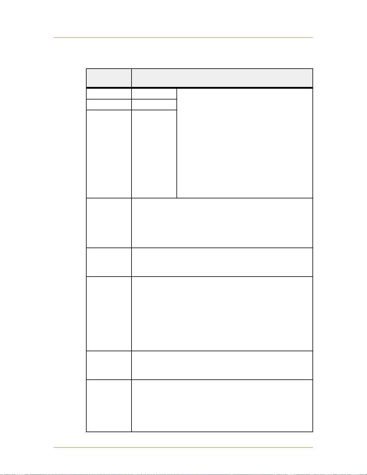
Advanced Energy
Table 4‑18. AE Bus command 14 remote control settings, resets, and
overrides
Command 14
2 Host Port Normal behavior:
Description
value
4 User Port
6 Front panel
• Host port and User Port: If you did not
specify remote control overrides, then you
have no button or soft key functionality on
the front panel, but you have full display
functionality (for example, the display key
works and values are displayed).
• All domains (host port, User Port, and front
panel): If you specified remote control
overrides, then those overrides determine
the behavior of the knob, the RF On/Off
keys, and Matching keys).
10 Resets front panel control to normal behavior. Use this to reset
remote control after sending values 11, 12, or 13. Normal behavior
is the behavior defined by Command 14 (value of 2, 4, or 6) plus
remote control overrides. Commands 11, 12, and 13 act as
additional filters for restricting the front panel buttons and knobs.
The unit continues to show values on the display.
11 Disable front panel Program and Presets soft keys.
Exceptions: None (Remote control overrides set from the front
panel do not affect the Program and Presets soft keys)
12 Set front panel to remote operation, where all soft and regular keys
are disabled, except the Display soft key:
• Disable front panel Program and Presets soft keys.
• No change of remote mode by front panel.
• Disable RF On and RF Off keys, set point (knob), and
Matching keys (unless there is a local override).
Exceptions: Remote control overrides set from the front panel.
13 All soft and regular keys (and all menus) are disabled, including
the Display soft key.
Exceptions: Remote control overrides set from the front panel.
20 Resets front panel display to the normal behavior. Use this to reset
remote control after sending values 22 or 23. Normal behavior is
the behavior defined by command 14 (value of 2, 4, or 6) plus
remote control overrides.
Values 20, 22, and 23 control the front panel display; values 22
and 23 also disable the front panel keys and knob.
4‑52 Communication Controls 57023916-00B

Cesar® Generator
Table 4‑18. AE Bus command 14 remote control settings, resets, and
overrides (Continued)
Command 14
Description
value
22 All front panel display values are turned off except Ready,
Active, or Error.
All front panel overrides are disabled.
Exceptions: none.
23 All front panel display values are disabled.
All front panel overrides are disabled.
Exceptions: none.
AE BUS COMMAND STATUS RESPONSE (CSR) CODES
When the Cesar unit receives a command requesting a change in unit operation
(command numbers 1 through 127), or when the Cesar unit receives any command
that it rejects (command numbers 1 through 255), it responds with a command status
response (CSR) code. The CSR is a single-byte number that indicates whether the
unit accepted or rejected the command and, in the case of rejection, the reason the
unit could not respond to the command.
Table 4‑19. AE Bus command status response (CSR) codes
Code Meaning
0 Command accepted
The following CSR codes are sent in response to a command that was not accepted
and provide an indication of why the command was not accepted
1 Control code is incorrect
2 Output is on (change not allowed)
4 Data is out of range
7 Active fault(s) exist
9 Data byte count is incorrect
19 Recipe is active (change not allowed)
50 The frequency is out of range
51 The duty cycle is out of range
53 The device controlled by the command is not detected
99 Command not accepted (there is no such command)
57023916-00B Communication Controls 4‑53

Advanced Energy
AE BUS PORT COMMAND SET
The Cesar unit communication interfaces use two types of AE Bus commands:
• Commands 1 through 127 request a change to the Cesar unit, such as changing
• Command numbers 128 through 255 request information from the unit, such as
Unless otherwise specified for individual commands, AE Bus protocol is little
endian, which means that all values greater than 1 byte are sent least significant byte
first.
Most AE Bus commands are the same for all of the available interfaces. Differences
are noted where they exist.
a setting in the unit. The unit responds to these commands by sending a
command status response (CSR). This single-byte response indicates whether
the unit has accepted or rejected the command and, in the case of rejection, the
reason the unit could not respond to the command.
unit settings. The unit responds to these commands by sending the data
requested if the command was successful, and a CSR if the command was not
successful.
Your unit may not have all features listed here. If you issue a command for a feature
that your unit does not have, the unit returns CSR 99, Command not accepted.
Table 4‑20. AE Bus Commands
Command Description Data Bytes
Sent
0
This command is always accepted but is ignored. 0 1
null
This command
is for
PROFIBUS
only.
Data Bytes
Returned
(CSR only)
4‑54 Communication Controls 57023916-00B

Table 4‑20. AE Bus Commands (Continued)
Command Description Data Bytes
Sent
Cesar® Generator
Data Bytes
Returned
1
Turn output
off
2
turn output on
Turns off RF output.
This command shuts the RF output off
immediately if ramping in not enabled. Otherwise
it starts the RF output off ramp. If issued while on
or off ramping is in progress, the RF output is
shut off immediately. If issued while a power
ramping recipe is in progress, the RF output is
shut off immediately and the recipe is suspended.
A subsequent command 2 turn output on will
resume the recipe execution. See “Controlling RF
On With AE Bus Commands” on page 4-80 for
a discussion of the methods to control RF on and
off.
All latched faults are cleared in the fault status
register. It does not clear any faults that are
currently active.
This command is accepted regardless of control
mode.
Read back with command 162.
Turns on RF output.
Turns on the RF output if there are no active or
latched faults.
0 1
(CSR only)
0 1
(CSR only)
This command is accepted only when host port
control mode is active. It is not accepted when a
power ramping recipe is being programmed
(commands 19, 21, 22 and 23). If the recipe is
already programmed, then this command executes
the recipe.
See “Controlling RF On With AE Bus
Commands” on page 4-80 for a discussion of
the methods to control RF on and off.
Read back with command 162.
57023916-00B Communication Controls 4‑55

Advanced Energy
Table 4‑20. AE Bus Commands (Continued)
Command Description Data Bytes
Sent
Data Bytes
Returned
3
set regulation
mode
4
set forward
power limit
Sets the regulation mode. The regulation mode
can be changed between forward, real, and DC
Bias regulation modes while the RF output is on.
This command is accepted only when host port
control mode is active. It is not accepted when a
power ramping recipe is being or has been
programmed (commands 19, 21, 22 and 23) or is
running.
Send one data byte, indicating the desired
regulation mode:
• 6 = Forward power regulation
• 7 = Real power regulation (sometimes called
load power regulation or delivered power
regulation)
• 8 = DC Bias regulation (sometimes called
external power regulation)
See also commands 4, 8, 9, and 10.
Read back with command 154.
Limits the forward power in DC Bias regulation
mode (set with command 3) by specifying the
maximum forward power that can be delivered.
The forward power limit is accepted in all
regulation modes but is only applied while in DC
bias regulation mode.
This command is accepted only when host port
control mode is active. It is not accepted when a
power ramping recipe is being programmed
(commands 19, 21, 22 and 23) or is running.
Send two data bytes, least significant byte first,
representing the maximum forward power in
watts.
1 1
(CSR only)
2 1
(CSR only)
• Accepts a value of 5% to 100% of maximum
power
Read back with command 169.
4‑56 Communication Controls 57023916-00B

Table 4‑20. AE Bus Commands (Continued)
Command Description Data Bytes
Sent
Cesar® Generator
Data Bytes
Returned
5
set reflected
power limit
8
set power set
point
Sets the maximum reflected power. The reflected
power limit is in effect for all regulation modes.
The reflected power limit can be changed while
the RF output is on.
This command is accepted only when host port
control mode is active.
Send two data bytes, least significant byte first,
representing the reflected power limit as a
percentage of maximum power.
• Accepts a value of 1 watt through the
maximum reflected power (see electrical
specifications table). The maximum value is
also limited by cable attenuation factors
settings that are negative. The cable
attenuation factor is changeable through a
front panel menu setting.
Read back with command 170.
Sets the output set point level for the selected
regulation mode (set with command 3).
This command is accepted only when host port
control mode is active. It is not accepted when a
power ramping recipe has been programmed
(commands 19, 21, 22 and 23) or is running.
Send two data bytes, least significant byte first,
representing the set point level in watts or volts:
2 1
(CSR only)
2 1
(CSR only)
• Watts, if in forward or real power regulation
modes. Accepts a value of 0 to the unit’s
maximum RF output power or the user
power limit.
• Volts, if in DC Bias regulation mode.
Accepts a value of 0 to maximum external
feedback value.
Read back with command 164.
57023916-00B Communication Controls 4‑57

Advanced Energy
Table 4‑20. AE Bus Commands (Continued)
Command Description Data Bytes
Sent
Data Bytes
Returned
9
set maximum
external
feedback
10
set RF on time
limit
Sets the maximum external feedback value in
volts. It is only used when operating in DC Bias
regulation mode.
This command is accepted only when host port
control mode is active.
Send three data bytes, least significant byte first.
• Bytes 0 and 1 = Maximum external feedback
in V. Accepts a value in the range of 100 to a
factory set maximum, typically 4000.
• Byte 2 is only for compatibility and is
ignored
There is no read back command for the current
setting.
This command sets the maximum RF on time in
seconds. When the time since an RF on command
exceeds the configured limit without an RF off
command, RF is switched off and the error E52
RF on time limit is issued.
This command is accepted only when host port
control mode is active.
Send 2 data bytes, least significant byte first:
3 1
(CSR only)
2 1
(CSR only)
• Acceptable values are for the time limit are 0
– 3600 seconds. A value of 0 deactivates this
function.
Read back with command 243.
11
select active
target
Select one of four target lifetime counters to
activate. These counters integrate power and time
while the RF output is on. When sending
1 1
(CSR only)
commands through a PROFIBUS interface, use
this command first to select the target, then use
command 12 to specify the target life.
This command is accepted only when host port
control mode is active.
Send one data byte.
• Accepts a value of 0 to 4.
If 0 is selected, then no target life timer will
count.
Read back with command 156.
4‑58 Communication Controls 57023916-00B

Table 4‑20. AE Bus Commands (Continued)
Command Description Data Bytes
Sent
Cesar® Generator
Data Bytes
Returned
12
set target life
AE Bus and
Ethernet
version. See
next row for
Profibus
version of
command
12
set target life
Profibus
version. See
previous row
for AE Bus/
Ethernet
version of
command
Sets the target life in hundredths of kilowatt hours
for one of four targets. The selected target lifetime
counter is also reset to zero. When an enabled
target lifetime counter exceeds its target life a
warning status bit will be set.
This command is accepted only when host port
control mode is active.
Send five data bytes, least significant byte first.
• Byte 0 = The target number. Acceptable
values are 1 to 4.
• Bytes 1 through 4 = The target life in
hundredths of kWh (for example, 100 =
1 kWh). Acceptable values are 1 to 2160000.
Read back with command 157.
Sets the target life, in hundredths of kilowatt
hours, of the currently active target (see command
11). The selected target lifetime counter is also
reset to zero. When an enabled target lifetime
counter exceeds its target life a warning status bit
will be set.
This command is accepted only when host port
control mode is active.
Send three data bytes, least significant byte first.
5 1
(CSR only)
3 1
(CSR only)
• Bytes 0 to 2 = The target life in hundredths
of kWh (for example, 100 = 1 kWh).
Acceptable values are 1 to 2160000.
Read back with command 157.
57023916-00B Communication Controls 4‑59

Advanced Energy
Table 4‑20. AE Bus Commands (Continued)
Command Description Data Bytes
Sent
Data Bytes
Returned
13
set match
network
control
Sets the tuner control if the Cesar generator is
connected to a VarioMatch or Navio matching
network through the Matching interface.
Sets the match network control mode if a match
network is connected and powered on. Tune mode
Automatic with initialization uses the last
commanded capacitor position as an initial preset
position when RF power is commanded off. It
returns a CSR of 53 if a match network is not
connected or not powered on. The match network
must be connected through the Matching
interface connector, and must be either a
VarioMatch, Navio, or other match network that
is electrically and functionally compatible.
This command is accepted only when host port
control mode is active.
Send one data byte:
• 0 = Manual
• 1 = Automatic
• 2 = Automatic with initialization
1 1
(CSR only)
Read back with command 163.
4‑60 Communication Controls 57023916-00B

Table 4‑20. AE Bus Commands (Continued)
Command Description Data Bytes
Sent
Cesar® Generator
Data Bytes
Returned
14
select active
control mode
Sets the generator’s active control mode.
This command is accepted in host port, User
Port, and front panel control modes.
Send one data byte:
• 2 = Host port (serial) control
• 4 = User Port (analog) control
• 6 = Front panel (local) control
Changing between control modes 2, 4, and 6
while the RF output is on will force the RF output
off before changing the mode.
Valid modes that affect front panel operational
control are:
• 10 = Reset front panel display and control to
normal operation if in modes 11, 12, or 13
• 11 = Disable front panel program menu and
presets
• 12 = Disable all front panel functions except
the Display soft key
1 1
(CSR only)
• 13 = Disable all front panel functions
Valid modes that affect front panel display
content are:
• 20 = Reset front panel display to normal
operation if in modes 22 or 23
• 22 = Set front panel display to show only
Ready, Active, or Error
• 23 = Turn off front panel display (shows …
in display lower right corner)
For additional information on how to use
command 14, see “Activating Host Port Remote
Control (AE Bus Command 14)” on page 4-51.
Read back with command 155.
57023916-00B Communication Controls 4‑61

Advanced Energy
Table 4‑20. AE Bus Commands (Continued)
Command Description Data Bytes
Sent
Data Bytes
Returned
19
set number of
recipe steps
Sets the number of recipe steps when creating a
power ramping recipe. It is the first in a sequence
of commands used to program a recipe. The initial
set point that precedes step 1 is always 0. The
final set point that follows the last step is always
0. Each recipe step consists of three components,
which can be set in any order:
• A set point (use command 21)
• A ramp time—applies to the set point change
in a recipe step (use command 22)
• A run time—applies after the set point is
reached and the next recipe step (use
command 23)
The full sequence of steps to set up a recipe:
1. Send command 19 to specify the number of
steps.
2. For each step, set up recipe parameters with
commands 21, 22, and 23.
Once all recipe parameters are programmed,
recipe construction is complete and the RF output
may be turned on.
This command is accepted only when host port
control mode is active. It is not accepted when the
RF output is turned on.
Send one data byte, representing the desired
number of recipe steps:
1 1
(CSR only)
• Accepts a value of 0 through 2
• 0 disables power ramping and RF-On
ramping functions.
See “Controlling RF On With AE Bus
Commands” on page 4-80 for a discussion of
the three methods to control RF on.
There is no read back command for the current
setting.
4‑62 Communication Controls 57023916-00B
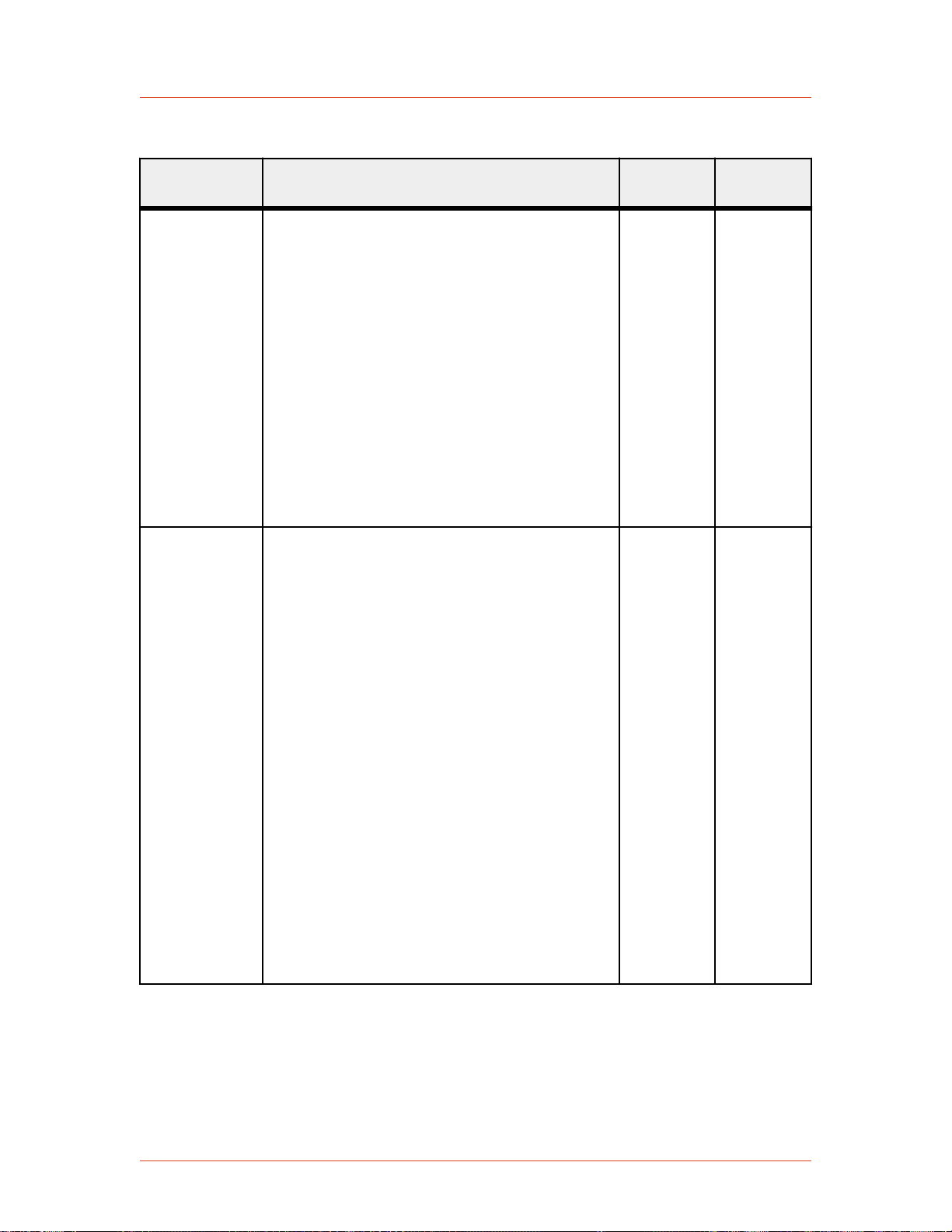
Table 4‑20. AE Bus Commands (Continued)
Command Description Data Bytes
Sent
Cesar® Generator
Data Bytes
Returned
21
recipe step/
ramp time
22
recipe step/set
point
Sets the ramp time for a given recipe step. You
must first set the number of recipe steps with
command 19. See command 19 for a discussion of
recipes and their construction.
This command is accepted only when host port
control mode is active. It is not accepted when the
RF output is turned on.
Send three data bytes, least significant byte first:
• Byte 1 = Recipe step number (1 to 2)
• Bytes 2 and 3 = Ramp time value in tenths of
a second. Send a value from 0 to
36000 (36000 = one hour)
Read back with command 191.
Sets the set point for a given recipe step. You
must first set the number of recipe steps with
command 19. See command 19 for a discussion of
recipes and their construction.
This command is accepted only when host port
control mode is active. It is not accepted when the
RF output is turned on.
Send three data bytes, least significant byte first.
3 1
(CSR only)
3 1
(CSR only)
• Byte 1 = Recipe step number (1 to 2)
• Bytes 2 and 3, least significant byte first =
Set point value in watts or volts:
◦ Watts, if in forward or delivered power
regulation modes. Accepts a value of 0 to
the unit’s maximum RF output power or
the user power limit.
◦ Volts, if in external (DC Bias) regulation
mode. Accepts a value of 0 to maximum
external feedback value.
Read back with command 188.
57023916-00B Communication Controls 4‑63

Advanced Energy
Table 4‑20. AE Bus Commands (Continued)
Command Description Data Bytes
Sent
Data Bytes
Returned
23
set recipe step/
run time
24
save presets
Sets the run time for a specified recipe step. You
must first set the number of recipe steps with
command 19. See command 19 for a discussion of
recipes and their construction.
This command is accepted only when host port
control mode is active. It is not accepted when the
RF output is turned on.
Send three data bytes, least significant byte first.
• Byte 1 = Recipe step number (1 to 2)
• Bytes 2 and 3 = Run time in tenths of a
second. Send a value from 0 to 36000 (36000
= one hour)
Read back with command 188.
Saves the current settings of the generator
(everything except device configuration, arc
information, and target life settings) to EEPROM
as a numbered preset.
This command is accepted only when host port
control mode is active. It is not accepted when the
RF output is turned on.
Send 1 data byte:
3 1
(CSR only)
1 1
(CSR only)
• Acceptable values for the preset number are
1 to 5.
25
restore presets
Restores the numbered preset to the current
operational state of the generator.
1 1
(CSR only)
This command is accepted only when host port
control mode is active. It is not accepted when the
RF output is turned on.
Send 1 data byte:
• Acceptable values for the preset number are
1 to 5.
4‑64 Communication Controls 57023916-00B

Table 4‑20. AE Bus Commands (Continued)
Command Description Data Bytes
Sent
Cesar® Generator
Data Bytes
Returned
27
set pulsing
configuration
Controls the pulsing configuration.
The pulsing mode may be changed while the RF
output is turned on. Mode 1 selects the internal
pulse function established by commands 93 and
96. Modes 2 through 5 utilize the User Port
blanking/pulsing input to control the pulsing
function. Modes 4 and 5 gate the internally
generated pulse function established by
commands 93 and 96.
This command is accepted only when host port
control mode is active.
Send one data byte to set the pulsing mode.
• 0 = Pulsing off
• 1 = Internal pulsing
• 2 = External pulsing (Hi = RF on; Low = RF
off)
• 3 = External pulsing inverted (Hi = RF off;
Low = RF on)
• 4 = Gated internal pulsing (Hi = CW; Low =
Pulse)
1 1
(CSR only)
• 5 = Gated internal pulsing inverted (Hi =
Pulse; Low = CW)
Read back with command 177.
57023916-00B Communication Controls 4‑65

Advanced Energy
Table 4‑20. AE Bus Commands (Continued)
Command Description Data Bytes
Sent
Data Bytes
Returned
29
set remote
control
override
Sets the front panel and User Port override
controls. Each bit of the mask enables partial front
panel or User Port control of that function.
This command is accepted only when host port
control mode is active. The remote control
override can be changed while the RF output is
turned on.
Send one data byte to define overrides:
• Bit 0 = Enable front panel RF on/off buttons
• Bit 1 = Enable front panel Rotating knob
• Bit 2 = Enable front panel Matching keys
• Bit 3 = Enable setting RF on/off from the
User Port
• Bit 4 = Enable setting RF power set point
from the User Port
To set remote control overrides, use the values in
Table 4-21 on page 4-81. For a description of
how the overrides interact, see “Setting and
Disabling Remote Control Override” on page 5-
35.
1 1
(CSR only)
30
set user port
scaling
There is no read back command for this setting.
Sets User Port (analog) voltage scaling.
This command is accepted only when host port
control mode is active.
Send one data byte:
• The value specified is divided internally by 2
giving 0.5 volt granularity.
• Acceptable values for the User Port scaling
parameter are 4 to 40 (2 to 20 V).
Read back with command 158.
1 1
(CSR only)
4‑66 Communication Controls 57023916-00B

Table 4‑20. AE Bus Commands (Continued)
Command Description Data Bytes
Sent
Cesar® Generator
Data Bytes
Returned
31
set RF-on/off
ramping rise
time
32
set RF-on/off
ramping fall
time
Sets ramping rise time. Setting the ramp rise time
to zero turns off the ramping function and
subsequent command 151 report RF-on
ramping parameters will return 0 for both rise
and fall times. The ramp rise time can be set while
the RF output is on, however the ramp rise time is
not allowed to change during a ramp (rise or fall)
that is currently in progress.
This command is accepted only when host port
control mode is active.
Send two data bytes, least significant byte first:
• Ramp rise time in tenths of seconds.
• Acceptable values for the ramp rise time
parameter are 0 to 2400 tenths of seconds (4
minutes).
See “Controlling RF On With AE Bus
Commands” on page 4-80 for a discussion of
the three methods to control RF on.
Read back with command 151.
Sets ramping fall time. Setting the ramp fall time
to zero turns off the entire ramping function and
subsequent command 151 report RF-on/off
ramping parameters will return 0 for both rise
and fall times. The ramp fall time can be set while
the RF output is on, however the ramp fall time is
not allowed to change during a ramp (rise or fall)
that is currently in progress.
This command is accepted only when host port
control mode is active.
Send two data bytes, least significant byte first:
2 1
(CSR only)
2 1
(CSR only)
• Ramp fall time in tenths of seconds.
• Acceptable values for the ramp fall time
parameter are 0 to 2400 tenths of seconds (4
minutes).
See “Controlling RF On With AE Bus
Commands” on page 4-80 for a discussion of
the three methods to control RF on.
Read back with command 151.
57023916-00B Communication Controls 4‑67

Advanced Energy
Table 4‑20. AE Bus Commands (Continued)
Command Description Data Bytes
Sent
Data Bytes
Returned
33
set reflected
power
parameters
Sets reflected power limit parameters.
The reflected power limit parameters can be
changed while the RF output is on. This command
is accepted only when host port control mode is
active.
Send three data bytes, least significant byte first.
• Byte 1 = The number of seconds (after
reaching the limit set by bytes 2 and 3) until
RF is turned off.
◦ Accepts a value of 0 s to 200 s
• Bytes 2 and 3 = Power limit trigger in W.
◦ Acceptable values are 1 to the lesser of the
value set by command 5 set reflected
power limit or the product of the unit’s
maximum RF output power and the
reflected power factor, both of which are
set at the factory.
Setting the time limit and power limit trigger
value to 0 disables this function.
Read back with command 152.
3 1
(CSR only)
69
set serial port
baud rate
This command
is for AE Bus
only. Do not
use with
PROFIBUS and
Ethernet.
Sets the serial port baud rate.
This command is accepted only when host port
control mode is active.
Send three data bytes
• Byte 1 is only for compatibility and is
ignored
• Bytes 2 and 3 set the baud rate (send least
significant byte first). Valid baud rates are:
◦ 9600
◦ 19200
◦ 38400
◦ 57600
◦ 115,200 (for 115200, send 0)
Read back with command 212.
3 1
(CSR only)
4‑68 Communication Controls 57023916-00B

Table 4‑20. AE Bus Commands (Continued)
Command Description Data Bytes
Sent
Cesar® Generator
Data Bytes
Returned
93
set pulsing
frequency
96
set pulsing
duty cycle
Sets the RF pulsing frequency. Any combination
of pulsing frequency and duty cycle that results in
an RF output on time of less than 16 μs is invalid
and will return a CSR error code. See command
96 for a discussion of frequency and duty cycle
combinations.
This command is accepted only when host port
control mode is active.
Send four data bytes, least significant byte first,
representing the pulsing frequency in Hz.
• Accepts a value from 1 Hz to the maximum
RF pulse frequency in Hz. For the range, see
the RF pulse frequency specification in the
Specification chapter.
For backward compatibility and for PROFIBUS,
this command accepts 3 data bytes and it sets the
fourth byte to zero.
Read back with command 193.
Sets the RF pulsing duty ON time in increments
of 1%.
This command is accepted only when host port
control mode is active.
Send two data bytes:
3 or 4 1
(CSR only)
2 1
(CSR only)
• 1 to 99 (in percent), which represents the RF
output ON time.
The minimum duty cycle for a given pulsing
frequency can be determined by the expression:
MinimumDuty = (PulseDelay + 3.6)
* PulseFrequency * 0.000001
(where PulseDelay is factory configured).
Any combination of pulsing frequency and duty
cycle that results in an RF output on time of less
than 16 µs is invalid and will return a CSR error
code.
Read back with command 196.
57023916-00B Communication Controls 4‑69

Advanced Energy
Table 4‑20. AE Bus Commands (Continued)
Command Description Data Bytes
Sent
Data Bytes
Returned
111
initialize
capacitors
112
move load
capacitor
position
Moves load and tune capacitors of a connected
VarioMatch or Navio matching network to the
factory set minimum position. This command will
not work with other matching networks unless
they are electrically and functionally compatible
and are connected through the Matching interface
connector. The command returns a CSR of 53 if a
match network is not connected or not powered
on.
This command is accepted only when host port
control mode is active.
Send the command with no data bytes.
Moves the load capacitor motor of a connected
VarioMatch or Navio matching network to the
specified percentage position. This command will
not work with other matching networks unless
they are electrically and functionally compatible
and are connected through the Matching interface
connector. The command returns a CSR of 53 if a
match network is not connected or not powered
on.
This command is accepted only when host port
control mode is active.
0 1
(CSR only)
2 1
(CSR only)
119
explicit
PROFIBUS
fault clear
This command
is for
PROFIBUS
only. Do not
use with AE
Bus and
Ethernet.
Send two data bytes (LSB first) to specify the
load position in tenths of a %.
• Acceptable values for the load position must
be within the factory set range set (typically
40 – 960).
Read back with command 175.
Clears PROFIBUS fault and error code register.
Send one data byte.
0 1
(CSR only)
4‑70 Communication Controls 57023916-00B
 Loading...