

Page 1
ADT Security Services, Inc.
1750 Clint Moore Road
Boca Raton, FL 33431
(561) 988-3600
Unimode 400 Multi-Net
Analog Fire Panel
Operations Manual
Document 50709
12/15/99 Revision:
PN 50709:A1 ECN 99-551
A
Page 2

Installation Precautions
- Adherence to the following will aid in problem-free installation with long-term reliability:
WARNING - Several different sources of power can be connected to the fire alarm
control panel. Disconnect all sources of power before servicing. Control unit and
associated equipment may be damaged by removing and/or inserting cards,
modules, or interconnecting cables while the unit is energized. Do not attempt to
install, service, or operate this unit until this manual is read and understood.
CAUTION - System Reacceptance Test after Software Changes: To ensure
proper system operation, this product must be tested in accordance with NFPA 721993 Chapter 7 after any programming operation or change in site-specific software.
Reacceptance testing is required after any change, addition or deletion of system
components, or after any modification, repair or adjustment to system hardware or
wiring.
All components, circuits, system operations, or software functions known to be
affected by a change must be 100% tested. In addition, to ensure that other
operations are not inadvertently affected, at least 10% of initiating devices that are
not directly affected by the change, up to a maximum of 50 devices, must also be
tested and proper system operation verified.
This system meets NFPA requirements for operation at 0-49O C/32-120O F and
at a relative humidity of 85% RH (non-condensing) at 30
useful life of the system's standby batteries and the electronic components may
be adversely affected by extreme temperature ranges and humidity. Therefore,
it is recommended that this system and its peripherals be installed in an
environment with a nominal room temperature of 15-27
Verify that wire sizes are adequate for all initiating and indicating device loops.
Most devices cannot tolerate more than a 10% I.R. drop from the specified device
voltage.
O
C/86O F. However, the
O
C/60-80O F.
Like all solid state electronic devices, this system may operate erratically or can
be damaged when subjected to lightning induced transients. Although no system is
completely immune from lightning transients and interferences, proper grounding will
reduce susceptibility. Overhead or outside aerial wiring is not recommended, due to
an increased susceptibility to nearby lightning strikes. Consult with the Technical
Services Department if any problems are anticipated or encountered.
Disconnect AC power and batteries prior to removing or inserting circuit boards.
Failure to do so can damage circuits.
Remove all electronic assemblies prior to any drilling, filing, reaming, or punching
of the enclosure. When possible, make all cable entries from the sides or rear.
Before making modifications, verify that they will not interfere with battery,
transformer, and printed circuit board location.
Do not tighten screw terminals more than 9 in-lbs. Over tightening may damage
threads, resulting in reduced terminal contact pressure and difficulty with screw
terminal removal.
This system contains static-sensitive components. Always ground yourself with a
proper wrist strap before handling any circuits so that static charges are removed
from the body. Use static suppressive packaging to protect electronic assemblies
removed from the unit.
Follow the instructions in the installation, operating, and programming manuals.
These instructions must be followed to avoid damage to the control panel and
associated equipment. FACP operation and reliability depend upon proper
installation.
Fire Alarm System Limitations
An automatic fire alarm system - typically made up of smoke detectors, heat
detectors, manual pull stations, audible warning devices, and a fire alarm control
with remote notification capability can provide early warning of a developing fire.
Such a system, however, does not assure protection against property damage or
loss of life resulting from a fire.
Any fire alarm system may fail for a variety of reasons:
Smoke detectors may not sense fire where smoke cannot reach the detectors such
as in chimneys, in walls, or roofs, or on the other side of closed doors. Smoke
detectors also may not sense a fire on another level or floor of a building. A second
floor detector, for example, may not sense a first floor or basement fire. Furthermore, all types of smoke detectors - both ionization and photoelectric types, have
sensing limitations. No type of smoke detector can sense every kind of fire caused
by carelessness and safety hazards like smoking in bed, violent explosions,
escaping gas, improper storage of flammable materials, overloaded electrical
circuits, children playing with matches, or arson.
IMPORTANT! Smoke detectors must be installed in the same room as the
control panel and in rooms used by the system for the connection of alarm
transmission wiring, communications, signaling, and/or power. If detectors are
not so located, a developing fire may damage the alarm system, crippling its
ability to report a fire.
While installing a fire alarm system may make lower insurance rates
possible, it is not a substitute for fire insurance!
FCC Warning
Audible warning devices such as bells may not alert people if these devices are
located on the other side of closed or partly open doors or are located on another
floor of a building.
A fire alarm system will not operate without any electrical power. If AC power fails,
the system will operate from standby batteries only for a specified time.
Rate-of-Rise heat detectors may be subject to reduced sensitivity over time. For
this reason, the rate-of-rise feature of each detector should be tested at least once
per year by a qualified fire protection specialist.
Equipment used in the system may not be technically compatible with the control.
It is essential to use only equipment listed for service with your control panel.
Telephone lines needed to transmit alarm signals from a premise to a central
monitoring station may be out of service or temporarily disabled.
The most common cause of fire alarm malfunctions, however, is inadequate
maintenance. All devices and system wiring should be tested and maintained by
professional fire alarm installers following written procedures supplied with each
device. System inspection and testing should be scheduled monthly or as required
by National and/or local fire codes. Adequate written records of all inspections should
be kept.
WARNING: This equipment generates, uses, and can radiate radio frequency
energy and if not installed and used in accordance with the instruction manual, may
cause interference to radio communications. It has been tested and found to comply
with the limits for class A computing device pursuant to Subpart B of Part 15 of FCC
Rules, which is designed to provide reasonable protection against such interference
when operated in a commercial environment. Operation of this equipment in a
residential area is likely to cause interference, in which case the user will be required
to correct the interference at his own expense.
Technical Publishing Document PRECAULG.PM6 12/31/96
Canadian Requirements
This digital apparatus does not exceed the Class A limits for radiation noise
emissions from digital apparatus set out in the Radio Interference Regulations of the
Canadian Department of Communications.
Le present appareil numerique n'emet pas de bruits radioelectriques depassant les
limites applicables aux appareils numeriques de la classe A prescrites dans le
Reglement sur le brouillage radioelectrique edicte par le ministere des Communications du Canada.
Page 3

1. Introduction
Overview ......................................................................................................................1
Operating Features ........................................................................................................ 1
Components...................................................................................................................1
2. Using the Control Panel
Overview ......................................................................................................................3
System Status Indicator LEDs ......................................................................................3
Control Keys .................................................................................................................4
3. Operating Modes
Normal Operation ......................................................................................................... 5
Trouble Operation ........................................................................................................5
Fire Alarm ....................................................................................................................6
Supervisory Signal ........................................................................................................ 7
Non-Alarm Point Operation .........................................................................................7
Trouble Monitor Point Operation ................................................................................. 7
Notification Appliance Circuit (NAC) Operation ........................................................ 8
Control-By-Event Operation ........................................................................................ 8
Releasing Functions ...................................................................................................... 8
Intelligent Detector Functions .................................................................................... 10
Pre-Alarm Operation (AWACS) ................................................................................ 11
Time Functions ........................................................................................................... 11
Table of Contents
Overview ............................................................................................................11
Operating Coding Functions .............................................................................. 12
Presignal/Positive Alarm Sequence (PAS) Operation .......................................12
Special System Timers ....................................................................................... 13
Waterflow Circuits Operation ............................................................................ 13
Disable/Enable Operation ..................................................................................13
Style 6 Operation ............................................................................................... 13
4. Read Status
Overview ....................................................................................................................15
How to Enter Read Status ........................................................................................... 15
Read Status Options ...................................................................................................15
Read Status for Points and Zones ......................................................................16
Read Status for a Detector, Module, or Output .................................................16
Read History ...................................................................................................... 18
View Alarm History ........................................................................................... 18
View or Print Hidden History ............................................................................ 18
Presignal Delay ..................................................................................................19
Releasing Zones ................................................................................................. 19
Time Control Zones ...........................................................................................19
Holiday Zones .................................................................................................... 20
NAC Coding Zone .............................................................................................20
Pre-Alarm Zone .................................................................................................20
System Parameters ............................................................................................. 21
Annunciator Display Selections ......................................................................... 22
Example of Annunciator Display Selections .....................................................22
Unimode 400 Operations PN 50709:A1 12/15/99 iii
Page 4

Table of Contents 5. Voice Alarm Systems
5. Voice Alarm Systems
Overview ....................................................................................................................23
Operating Features ...................................................................................................... 23
In this Section ............................................................................................................. 23
Before you Begin ........................................................................................................24
AMG-1/AMG-EAudio Message Generator .............................................................. 25
AMG-1/AMG-E Overview ................................................................................ 25
AMG-1/AMG-E Operating Features .................................................................25
Operating the AMG-1 ........................................................................................ 26
Selecting AMG Group Functions ............................................................................... 27
Selecting AMG Tones and Messages.......................................................................... 28
ATG-2 Audio Tone Generator ...................................................................................31
ATG-2 Overview ............................................................................................... 31
How to Operate the ATG-2 ................................................................................32
Selecting Tones for the ATG-2 ..........................................................................32
Selecting a Primary (Evac) Channel Tone.......................................................... 33
Selecting a Secondary (Alert) Channel Tone .....................................................33
Select Operating Mode ......................................................................................33
Fire Fighter's Telephones (FFT-7/FFT-7S) ................................................................ 34
Overview ............................................................................................................34
FFT-7 Operating Components ........................................................................... 34
How to Operate the FFT-7 ................................................................................. 34
Audio Amplifiers ........................................................................................................35
Overview ............................................................................................................35
Audio Amplifier Features .................................................................................. 35
AA-30 Audio Amplifiers ............................................................................................ 36
AA-100/AA-120 Audio Amplifiers ...........................................................................37
Adjusting the Audio Gain Level (AA-30, AA-100/AA-120) ....................................38
Selecting the AA-100/AA-120 Backup Tone ............................................................. 38
AMG Voice Message Options .................................................................................... 39
Overview ............................................................................................................39
Installation .........................................................................................................39
iv Unimode 400 Operations PN 50709:A1 12/15/99
Page 5
1. Introduction
Overview
The Unimode400 is a modular, intelligent Fire Alarm Control Panel (FACP) with an
extensive list of powerful features. The CPU module, power supply module, and
cabinet combine to create a complete fire control system for most applications.
Optional modules mount to the chassis to provide additional output circuits.
Operating Features
• Alarm Verification selection per point, with tally.
• Positive Alarm Sequence (PAS) and Presignal per NFPA 721993.
• Silence Inhibit timer and Auto Silence timer.
• March time/temporal code for Notification Appliance Circuits (NACs).
• Zone coding for NACs if using an optional ADT-UZC-256.
• Alarm Silence/System Reset/Alarm Activate functions through M500M monitor
modules.
• Automatic time-of-day and day-of-week control functions, with holiday option.
• User-defined password and key-protected nonvolatile memory.
• AWACS (Advanced Warning Addressable Combustion Sensing) with nine field-
adjustable Pre-Alarm levels with programmable Control-by-Event (CBE)
• Operate automatic smoke or heat detector sounder base on action Pre-Alarm level,
with general evacuation on alarm level.
• Security alarm point option with separate audible signal code.
• Centralized voice paging and audible alarm signaling options.
• Programmable Control-by-Event control of outputs from individual alarm or
supervisory addressable devices.
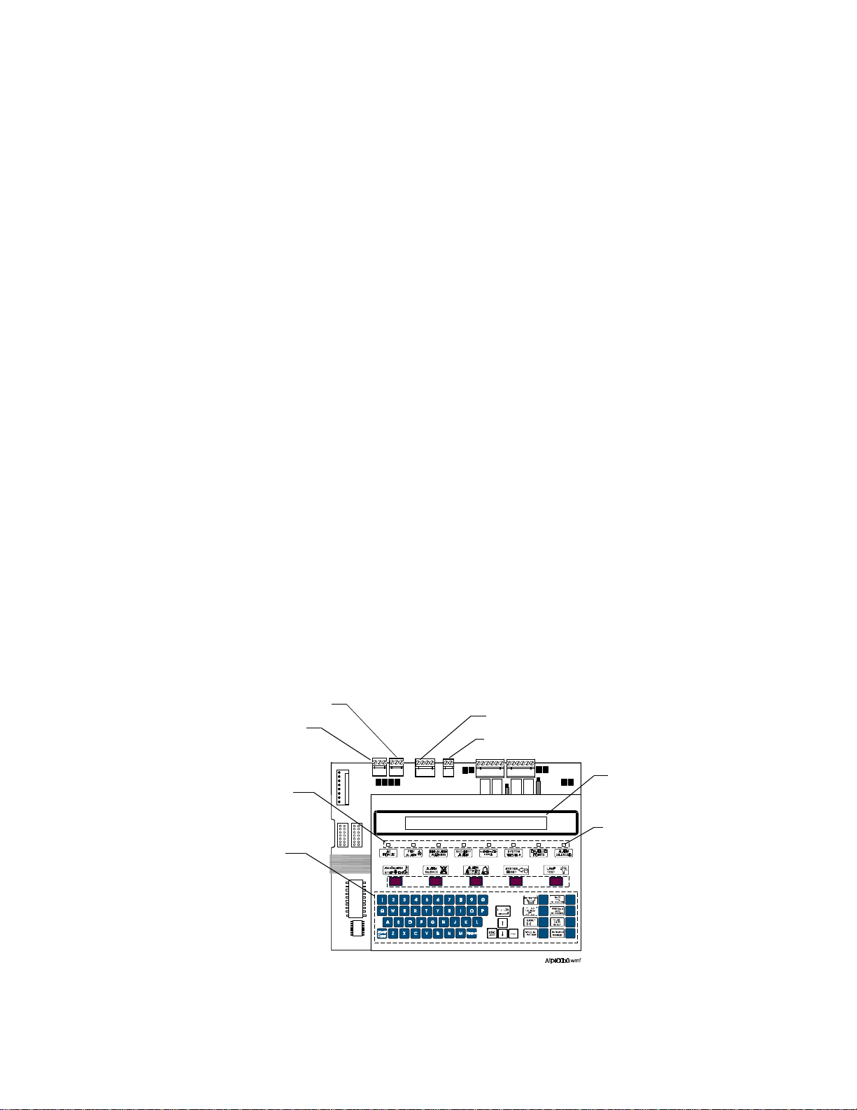
Components
Figure 1 shows components that affect operation of the control panel:
EIA-232 PC/Terminal Port
EIA-232 Printer Port
Control
Keys
Programming
Keypad
EIA-485 Terminal Mode Port
EIA-485 ACS Port
80-character (2 x 40) Liquid
Crystal Display (LCD)
System Status
LED Indicators
Figure 1 Control Panel Components
Unimode 400 Operations PN 50709:A 10/20/97 1
Page 6

Notes
2 Unimode 400 Operations PN 50709:A 10/20/97
Page 7
2. Using the Control Panel
Overview
Table 1 lists the controls and indicators and where to find information on their use:
Controls/Indicators Covered in...
Eight System Status Indicator LEDs System Status Indicator LEDs on page 3.
Five control keys Control Keys on page 4.
A panel sounder with a piezo that
Section 3. Operating Modes on page 5.
provides unique sounds for alarm,
trouble and supervisory/security
conditions
Table 1 Control and Indicators
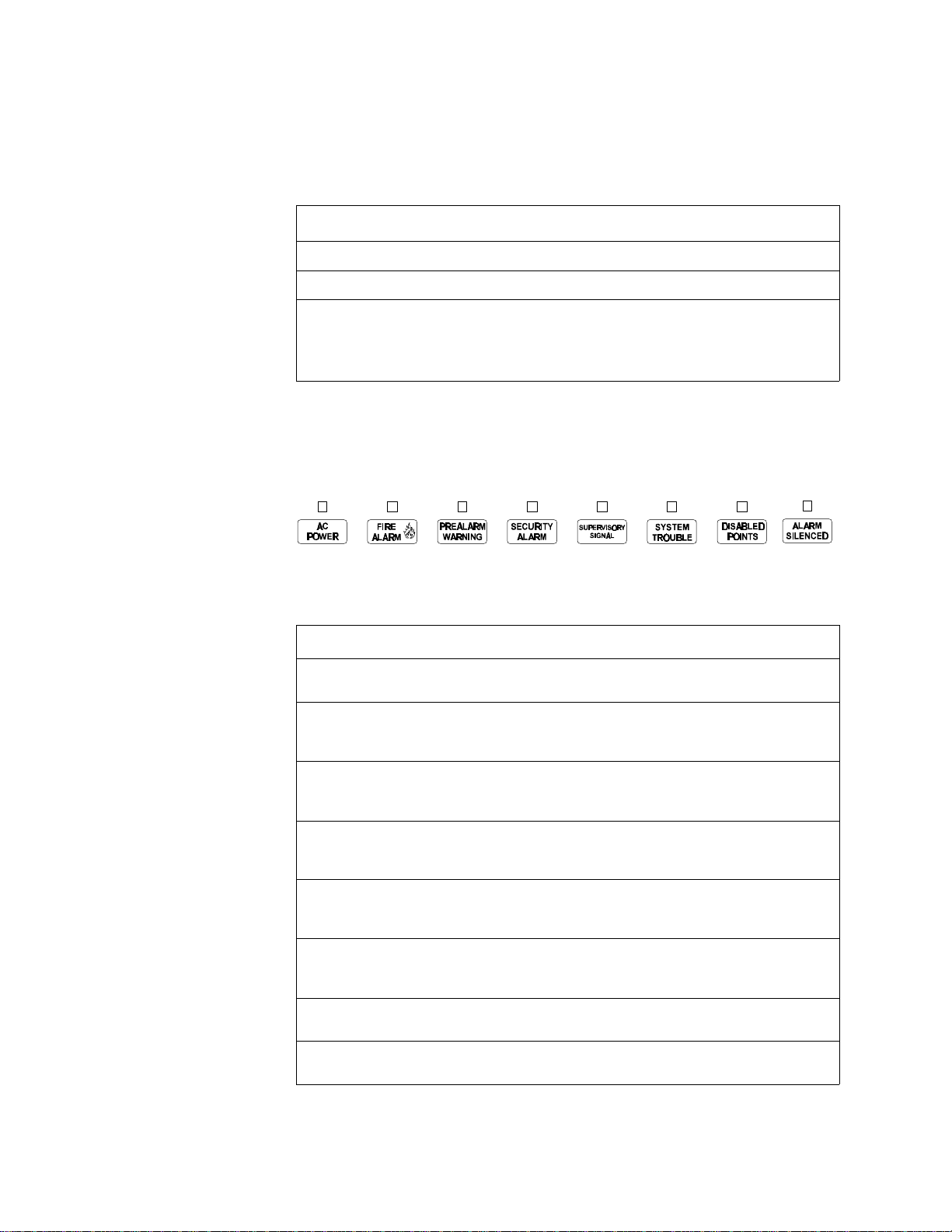
System Status Indicator LEDs
The control panel contains eight LED indicators with labels as shown in Figure 2:
Figure 2 System Status Indicator LEDs
Table 2 contains descriptions of the System Status Indicator LEDs:
Indicator Color When Active... To Turn Off...
AC Power Green Lights when the proper primary AC
power is applied.
Fire Alarm Red Flashes when a non-acknowledged Fire
Alarm exists. Lights steadily after you
acknowledge the alarm.
Turn off AC power.
Clear the alarm condition and
reset the system.
Pre-Alarm
Warning
Security
Alarm
Supervisory
Signal
System
Trouble
Disabled
Points
Alarm
Silenced
Yellow Flashes when a non-acknowledged
Pre-Alarm exists. Lights steadily after
you acknowledge the Pre-Alarm.
Blue Flashes when a non-acknowledged
Security Alarm exists. Lights steadily
after you acknowledge the alarm.
Yellow Flashes when a non-acknowledged
Supervisory Alarm exists. Lights
steadily after you acknowledge the alarm.
Yellow Flashes when a non-acknowledged
System Trouble exists. Lights steadily
after you acknowledge the trouble.
Yellow Lights when one or more system devices
are disabled.
Yellow Lights after an alarm condition occurs
and after pressing <Alarm Silence>.
Clear the alarm condition.
(Action Pre-Alarm requires a
system reset.)
Clear the Security Alarm
condition and reset the system.
Clear the signal. (Tamper
inputs require a system reset.)
Clear the trouble condition.
Enable or remove the disabled
device.
Press <Alarm Activate> or
<System Reset>.
Table 2 Descriptions of System Status Indicator LEDs
Unimode 400 Operations PN 50709:A 10/20/97 3
Page 8

2. Using the Control Panel Control Keys
Control Keys
The control panel provides five control keys, Acknowledge/Step, Alarm Silence, Alarm
Activate, System Reset, and Lamp Test.
Acknowledge Step Use the <Acknowledge/Step> key to respond to new alarm or
trouble signals. Pressing <Acknowledge/Step> causes the control panel to do the
following:
• silence the control panel sounder;
• change all indicators from flashing to steady;
• send an Acknowledge message to the history file, an optional printer, and an
optional ADT-LCD-80; and
• send a signal to silence the sounder on the ADT-LCD-80 and ACS annunciators.
You can also press the <Acknowledge/Step> key to display multiple alarms or troubles.
If more than one alarm or trouble exists, the control panel displays the next alarm or
trouble for 3 seconds (or until you press <Acknowledge/Step>), then displays the next
alarm or trouble.
Alarm Silence Use the <Alarm Silence> key to silence the control panel sounder as
well as sounders connected to Notification Appliance Circuits. Pressing <Alarm
Silence> causes the control panel to do the following:
• turn off the control panel sounder;
• turn off all silenceable output circuits;
• light the Alarm Silenced LED; and
• send an Alarm Silenced message to the history file, optional printer, and an
optional ADT-LCD-80.
Alarm Activate Use the <Alarm Activate> key to test notification appliances. Press
and hold the Alarm Activate switch for 2 seconds (to prevent accidental activation).
The control panel does the following:
• turns on all silenceable NACs;
• turns off the Alarm Silenced LED; and
• sends a Manual Evacuate message to the history file, optional printer, and an
optional ADT-LCD-80.
System Reset Use the <System Reset> key to reset the control panel. Press <System
Reset> and the control panel does the following:
• turns off all alarm-activated M500CH modules and NAC circuits;
• breaks resettable power to four-wire detectors; and
• sends an All Systems Normal message to the history file, optional printer, and an
optional ADT-LCD-80.
Any alarm or trouble that exists after a System Reset reactivates NACs, control outputs,
and panel audio and visual indicators.
Lamp Test Use the <Lamp Test> key to test the control panel LEDs and sounder.
Press and hold <Lamp Test> and the control panel does the following:
• lights all control panel LEDs;
• turns on the control panel sounder; and
• lights all segments of the LCD display.
4 Unimode 400 Operations PN 50709:A 10/20/97
Page 9

3. Operating Modes
Normal Operation
The system operates in Normal mode when no alarms or troubles exist. In Normal
mode, the control panel displays a system message as follows:
YOUR CUSTOM FORTY CHARACTER MESSAGEHERE
ALL SYSTEMS NORMAL11:30A TUE 02/11/97
Figure 3 All Systems Normal Message
In Normal mode, the control panel does the following functions at regular intervals:
• Polls all Signaling Line Circuit (SLC) devices and the four NACs to check for valid
replies, alarms, troubles, circuit integrity, and so on.
• Checks power supply troubles and batteries every 10 seconds.
• Sends a supervisory query on the ADT-LCD-80 and verifies proper response.
• Refreshes the LCD and the optional ADT-LCD-80 display and updates time.
• Scans the keypad for a System Reset or an Enter key press.
• Performs a detector automatic test operation.
• Tests system memory.
Note: M500CH modules report
both open and short circuit
messages.
Trouble Operation
The system goes into Trouble mode when the control panel detects an electrical or
mechanical fault. With no alarms, a control panel in Trouble mode does the following:
• Produces a pulsed audible tone;
• The System Trouble LED flashes;
• The trouble relay activates (MPS-400, TB5); and
• Sends a message to the LCD display, an optional ADT-LCD-80, an optional
printer, and the history file.
Figure 4 shows a typical Trouble message:
Type of event (trouble)
TROUBL PULL STATION I.C.U. WEST WING
Z1 INVALID REPLY 11:45PM TUE 02/11/97
Software zone
assigned (Zone 1)
Figure 4 Trouble Message
1. Press <Acknowledge/Step> to silence the panel sounder and switch the System
Trouble LED from flashing to steady—regardless of the number of troubles,
alarms, and supervisory signals.
Type of device
Custom descriptor for this
device location
Time and date
Type of trouble
2. Pressing <Acknowledge/Step> while at least one new alarm or trouble exists,
causes the control panel to send an Acknowledge message to the history file and an
optional printer.
Unimode 400 Operations PN 50709:A 10/20/97 5
Page 10

3. Operating Modes Fire Alarm
If the trouble clears (before or after pressing <Acknowledge/Step>), the control panel
sends a Clear Trouble message to the printer. Figure 5 shows a sample Trouble
Message:
TROUBL CONTROL MODULE ADDRESS 21 Z00 OPEN CIRCUIT 08:10A 08/20/95 M21
TROUBL CONTROL MODULE ADDRESS 22 Z00 OPEN CIRCUIT 08:12A 08/20/95 M22
Figure 5 Sample Trouble Message
If all troubles clear and no supervisory or fire conditions exist, the control panel does
the following:
• Returns to Normal mode;
• Sends an “All Systems Normal” message to the LCD display, the history file, an
optional ADT-LCD-80, an optional printer; and
• Restores troubles automatically even if troubles are not acknowledged.
Pressing <Alarm Silence> when only troubles exist, gives the same result as pressing
<Acknowledge/Step>. The Alarm Silenced LED does not light unless an alarm exists
in the system.
If multiple trouble conditions exist in the system, the LCD and optional ADT-LCD-80
displays automatically step through each trouble event every 3 seconds in the following
order:
1. Alarms, in order of address;
2. Supervisory, in order of address; or
3. Troubles, in order of address.
Press <Acknowledge/Step> and the display stops on the current trouble event for
1minute. Press <Acknowledge/Step> to continue.
Fire Alarm
The system goes into Fire Alarm mode when the control panel detects a fire alarm.
During Fire Alarm mode, the control panel does the following:
• Produces a steady audible tone;
• Activates the System Alarm relay (MPS-400, TB3) and flashes the System Alarm
LED;
• Displays Alarm in the status banner on the LCD display;
• Latches alarms so they cannot clear until the alarm initiating device returns to its
normal condition and the operator resets the control panel;
• Initiates any Control-by-Event actions;
• Starts timers (such as Silence Inhibit, Auto Silence); and
• Activates the general alarm zone (Z00).
Status banner ALARM
ALARM:PULL STATION I.C.U. WEST WING
VISITORS LOUNGE 11:55PM TUE 02/11/97
Figure 6 Fire Alarm Display
6 Unimode 400 Operations PN 50709:A 10/20/97
Page 11

Supervisory Signal 3. Operating Modes
Supervisory Signal
Note: You can program
Supervisory signals as Tracking
or Latching.
Supervisory signals cause the control panel to do the following:
• Produce a warbling audible tone;
• Turn on the Supervisory relay (MPS-400, TB4) and flash the Supervisory LED;
• Display “Active” in the status banner on the control panel; and
• Turn off the panel sounder for all Silenced alarms.
Status banner ACTIVE
ACTIVE TAMPER I.C.U. WEST WING
VISITORS LOUNGE 11:55PM TUE 02/11/97
Figure 7 Typical Supervisory Signal Display
Non-Alarm Point Operation
Non-Alarm points are M500M addressable modules that activate Control-by-Event.
These points do not activate the System Alarm LED or the panel sounder. Non-Alarm
points use three type codes: Non-Fire, Hazard Alert, and Fire Control.
Type Code Does this... Used for...
Non-fire
(Tracking)
Hazard Alert
(Latched)
Fire Control
(Tracking)
Activates Control-by-Event only. Energy management or other
non-fire situations.
Sends a message to the LCD display,
history file, printer, and ADT-LCD80 (status – Active), and overrides
code selection for NACs, regardless
of the zone F8 coding selection.
Sends messages to the LCD, history
file, printer and ADT-LCD-80.
Monitoring critical processes or
other hazardous situations, such
as a tornado.
Air handler shutdown, intended
to override automatic fire
functions.
Table 3 Non-Alarm Points
Trouble Monitor Point Operation
Trouble Monitor-type M500M modules monitor remote power supplies or other
external equipment. These types of M500M modules operate like troubles—but with
the following differences:
• The LCD display status banner displays “Active”;
• The type code is “Trouble Mon”;
• The modules latch—until the troubles are returned to normal condition and an
operator resets the control panel; and
• M500M modules can have Control-by-Event.
Unimode 400 Operations PN 50709:A 10/20/97 7
Page 12

3. Operating Modes Notification Appliance Circuit (NAC) Operation
Notification Appliance Circuit (NAC) Operation
The four NACs (TB7-TB10 on the MPS-400) have Control-by-Event and trouble
functions like M500CH addressable modules on the SLC loop. NAC circuits differ
from M500CH modules in the following ways:
• Addresses (last three characters in LCD field) are B01, B02, B03, or B04;
• The default type code field is “Bell Circuit”; and
• Control panel NACs, except those controlled with M500CH modules, can be used
for coded functions (March Time, California Code, Temporal, and Two-stage).
Control-By-Event Operation
Note: Zones F0-F9 are reserved
for special functions such as
cross-zoning (refer to the
Unimode400 Programming
Manual).
Control-by-event (CBE) control is done through 99 software zones. Each input point
(detector, M500M) and output point (M500CH, NAC) can be programmed to list up to
five software zones. Non-Alarm or Supervisory points do not activate software zone
Z00 (general alarm). You can list zone Z00 for output points, but you do not need to list
Z00 for input points.
Input and output devices with listed software zones work as follows:
• Inputs – When an input device (detector or M500M) activates, so do all software
zones listed to the input device.
Note: Refer to Appendix A for
more information about
releasing functions.
• Outputs – When a software zone activates, the output device turns on.
CBE Example Detector D102 lists zone Z05. B01 lists zone Z05 and zone Z07.
1. Detector D102 activates.
2. Zone Z05 activates.
3. B01 activates.
Releasing Functions
Overview Zones R0-R9 are reserved for releasing zones—providing up to ten
independent releasing operations. Each releasing zone includes the following options:
Option Description
Cross-zoning Select one of three types of cross-zoning. Refer to Table 5.
Delay Timer Select a 0–60 second delay before activating a zone.
Abort An abort switch-type code used to abort activation of a zone.
Manual Release Allows immediate zone activation by overriding the abort function,
cross-zone function, and delay timer.
Man. Rel. Delay Same as Manual Release, except releasing occurs 10 seconds after
“Man. Rel. Delay” is activated.
Soak Timer Automatically shuts off the releasing device. Select 0001-9999 seconds
for a Soak Timer or 0000 seconds for no Soak Timer.
Second Shot Reactivates release output after the Soak Timer times out.
Table 4 Cross Zoning Options
8 Unimode 400 Operations PN 50709:A 10/20/97
Page 13

Releasing Functions 3. Operating Modes
Using Cross Zoning Options Cross Zoning lets you program the control panel to
activate a releasing zone after two initiating devices are tripped. (If not using Cross
Zoning, set CROSS= to N.) Table 5 contains a summary of the types of cross zoning
and the conditions for activating a releasing zone.
Type Activates when...
Y Two or more detectors, all mapped to one of the ten releasing zones (R0-R9), are
tripped.
Z Two or more detectors, mapped to two different software zones and one of the ten
releasing zones (R0-R9), are tripped.
H At least one smoke detector and at least one heat detector, all mapped to one of the
ten releasing zones (R0-R9), are tripped.
Table 5 Cross Zoning Types
Note: Only the first non-special
zone listed in the zone map is
used to determine Cross=Z.
Cross Zoning Example Table 6 lists examples of devices mapped to releasing zones
(ZR1 stands for Releasing Zone 1).
Device Address Device Type Zone Mapping
D101 Detector Smoke ZR1 Z01
D102 Detector Smoke ZR1 Z01
D103 Detector Smoke ZR1 Z02
D104 Detector Heat ZR1 Z02
B01 Output Circuit (Rel Ckt) ZR1
Table 6 Devices Mapped to Releasing Zones
The following explanations apply to the examples listed in Table 6:
Cross=N An alarm from any detector activates the releasing circuit.
•
Cross=Y An alarm from any two detectors activates the releasing circuit.
•
Cross=Z Release requires the activation of two detectors mapped to different
•
zones: D101 and D102 cannot activate the releasing circuit because both detectors
are mapped to Z01; D101 and D103 can activate the releasing circuit because they
are mapped to different zones.
Cross=H Release requires activation of heat detector D104 and one smoke
•
detector (D101, D102, or D103).
Unimode 400 Operations PN 50709:A 10/20/97 9
Page 14

3. Operating Modes Intelligent Detector Functions
Intelligent Detector Functions
Note: For instructions on
selecting Intelligent Detector
Functions, refer to the
Unimode400 Programming
Manual.
Table 7 contains descriptions for intelligent detector functions used with the control
panel.
Function Description
Analog Display The control panel reads and displays analog information from the
198 analog detectors. The display shows the percent of the alarm
threshold for each detector.
Sensitivity Adjust Nine selections for manually setting intelligent detector alarm
levels within the UL range. If using Ionization detectors in duct
applications, set Sensitivity Adjust to Level 1.
Day/Night Sensitivity
Operation
Maintenance Alert When compensation reaches the limit of the amount of drift
Automatic Test
Operation
Type Code
Supervision
LED Control
Operation
Alarm Verification
and Counter Operation
You can program the system to automatically force smoke detectors
to minimum sensitivity during the day. Refer to “Time Control
Zones” on page 19.
compensation that can be safely applied, the control panel reports a
special trouble condition, per national fire code standards. This
condition also activates if the detector remains at very high or very
low measured air levels for an extended time.
The control panel performs an automatic test of each detector every
256 minutes. Failure to meet the test limits causes an AUTO TEST
Fail trouble.
The control panel monitors hardware device type codes (500 Series
detectors, 200 Series detectors, 3251 detectors, M500M, and
M500CH) for each installed device at regular intervals (an interval
can take up to 30 minutes for full capacity system). If a mismatch of
type compared to the program occurs, the control panel generates a
point trouble labelled Invalid Type.
A global program selection to prevent detector LEDs from blinking
during normal operation. A typical application is a sleeping area
where a blinking light can distract people. As a standard function,
the control panel allows all LEDs to turn on in alarm.
The control panel performs alarm verification on programmed
500Series, 200 Series, and 3251 intelligent smoke detectors. The
verification time is a global program selection of 0–30 seconds.
Each detector includes a verification counter, which displays the
number of times that a detector entered verification but did not
time-out to alarm. The counter increments to 99 and holds.
Table 7 Intelligent Detector Functions
10 Unimode 400 Operations PN 50709:A 10/20/97
Page 15

Pre-Alarm Operation (AWACS) 3. Operating Modes
Pre-Alarm Operation (AWACS)
Note: Refer to the
Unimode400 Programming
manual for more information on
AWACS applications.
If an 1251/2251 or 1551/2551 detector exceeds the programmed Pre-Alarm level, a PreAlarm condition occurs: the panel sounder and zone F9 activate; and the Pre-Alarm
LED lights. Figure 8 shows a sample Pre-Alarm message—sent to the LCD display,
optional ADT-LCD-80, optional printer, and history file—for a control panel
programmed for an Alert Pre-Alarm.
PREALARM SMOKE (PHOTO) I.C.U WEST WING
ALERT 105%/5 12:01A02/01/97D101
Detector programmed for a Pre-Alarm level of 5.
Shows the detector has reached 105%
of the programmed Pre-Alarm level.
The 105% is a real-time display and
tracks smoke levels.
Note: ALERT Pre-Alarms
automatically restore.
Shows the detector
programmed for ALERT
Pre-Alarm level.
Figure 8 Alert Pre-Alarm Message
If programming a control panel for an ACTION Pre-Alarm, the display remains the
same, but the word “Action” replaces “Alert”. The control panel latches for ACTION
Pre-Alarms and applies the programmed control functions.
Time Functions
Overview The control panel includes a real-time clock that provides time-of-day, date, and day-
of-week. The clock includes a lithium battery backup. Time normally displays in a
12-hour time format with month/day/year. Table 8 contains descriptions and typical
uses for time functions.
Time
Function
Time Control
Command
Description Typical Uses
Zones F5 and F6 are reserved for
control-by-time special functions,
intended for ancillary (non-fire)
applications (such as lighting
control, setting a thermostat, and so
forth).
For example, program zones F5
and F6 to activate at one time of
day and deactivate at another time,
on certain days of the week. You
can turn a non-fire control point on
and off, by using zone F5 or F6.
Day/Night
Sensitivity
Adjust
Holiday The control panel reserves zone F7
If a 1551/2551, 1251/2251, or 3251
detector CBE lists zone F5 or F6,
the control panel sets the detector
sensitivity to the minimum (low)
setting when zone F5 or F6 is
activated by the programmed date/
time in its CBE. When zone F5 or
F6 deactivates, the detector
sensitivity returns to the
programmed setting.
for setting holiday dates (up to 9
days). When the current date
matches any of the nine holiday
dates, the control panel activates
zone F7.
For day/night sensitivity use,
consider zones F5 and F6 as Day
zones.
Other uses for zone F7 include: a
special day-of-year control; or an
8th day in programming zones F5
and F6.
Table 8 Control Time Functions
Unimode 400 Operations PN 50709:A 10/20/97 11
Page 16

3. Operating Modes Time Functions
Operating Coding
Functions
Zone F8—reserved for NAC coding functions—is only used by panel NAC circuits
listing zone F8. You can select one of the four code types listed in Table 9:
Code Signal
March Time (default) 120 PPM (Pulses Per Minute)
Two-Stage Alert signal – 20 PPM; General alarm signal: Steady on
California 10 sec. on, 5 sec. off, repeats
Temporal 0.5 on, 0.5 off, 0.5 on, 0.5 off, 0.5 on, 1.5 off, repeats
Table 9 Zone F8 Type Codes
Notes on using coding functions:
M500CH modules Zone F8 does not work if listed in the CBE of M500CH modules.
Two-Stage When an alarm occurs, an NAC programmed for two-stage, and not
activated by another zone, pulses at 20 PPM. After 5minutes, the NAC changes to
steady on unless you press <Acknowledge/Step>. Pressing <Alarm Activate> on the
control panel changes the NAC pulse to steady. ICM-4/ICE-4 modules do not support
Two-Stage and turn on steady.
ICM-4/ICE-4 modules To enable California Code, cut D35 on the ICM-4 modules. If
D35 is not cut, ICM-4/ICE-4 modules turn on steady.
Presignal/Positive Alarm
Sequence (PAS)
Operation
Zone F0 is reserved for Presignal functions. Zone F0 can be used to delay control points
until an operator verifies an active control point. If including zone F0 in an M500CH or
NAC CBE list, zone F0 overrides all other CBE actions. Detectors and monitor modules
must list zone F0 in the CBE to be included in the Presignal/PAS operation.
If... And/or... Zone F0
an alarm occurs and there is no PAS inhibit type M500M activates
a second alarm activates or you press the alarm activate key, goes false
you select PAS and you do not press ACKNOWLEDGE
within 15seconds
goes false
Table 10 Presignal Operation
At the first alarm, a programmable 0–180 second timer starts. If a Signal Silence
occurs, the timer stops. If the delay timer expires, manual activation will activate
outputs mapped to zone F0. The System Alarm relay, the 4XTM Polarity Reversal
Alarm Output, and the 4XTM Municipal Box Output delay if PAS is selected, but do
not delay for Presignal operations
12 Unimode 400 Operations PN 50709:A 10/20/97
Page 17

Time Functions 3. Operating Modes
Special System Timers The control panel can operate with special system timers: Silence Inhibit, Auto Silence,
and Alarm Verification. Table 11 contains descriptions of how each timer works.
Timer Duration If selected...
Silence Inhibit 0-300 seconds Starts at first alarm and restarts with each new
alarm. Disables the Alarm Silence switch.
Waterflow Circuits
Operation
Disable/Enable
Operation
Auto Silence 600-900
seconds(0=no timer
selected)
Alarm
Verification
0-30 seconds The control panel ignores 1551/2551, 1251/
Automatically shuts off outputs selected as
silenceable after the programmed time elapses.
To restart the timer, press <Alarm Activate>.
2251, or 3251 smoke detectors for the Alarm
Verification time. If another point alarm occurs
during the Alarm Verification time, the control
panel dumps the timer and activates the alarm. If
a time-out and an alarm exist, the initiating
device CBE executes all standard functions. If at
time-out an alarm no longer exists in the alarm
initiating devices, the control panel increments a
verification counter (1-99) for the device and
returns to normal operation.
Table 11 Special System Timers
If an alarm originates from a monitor point with a waterflow type code, the control
panel disables the Alarm Silence switch. Refer to the Unimode400 Installation Manual
for information on Waterflow Circuits.
Disabled input points do not cause an alarm or any Control-by-Event activity. The
control panel does the following:
• holds all disabled output points in the off-state; and
• handles all disabled points as troubles, but displays DISABL in the status banner.
Caution: Disabling a zone disables all input and output devices associated with the
!
zone.
Style 6 Operation The control panel will detect a trouble in an SLC wired and programmed for Style 6 or
Style 7 and drive both ends of the line to maintain communication over the loop. The
trouble latches and displays on the panel as a Style 6 trouble type until you press
<System Reset>. Style 7 requires use of M500X modules.
Unimode 400 Operations PN 50709:A 10/20/97 13
Page 18

Notes
14 Unimode 400 Operations PN 50709:A 10/20/97
Page 19

Note: Refer to the
Unimode400 Programming
Manual for information on
Alarm and Pre-Alarm sensitivity.
Note: If attempting to read a
point that is not installed, the
control panel displays NOT
INSTALLED.
4. Read Status
Overview
Read Status functions do not require a password. The control panel will continue to
provide fire protection while in Read Status. You can enter Read Status while in Fire
Alarm or Trouble mode. If a new alarm or trouble occurs during these functions, the
control panel automatically exits Read Status.
How to Enter Read Status
Press <Enter>. The control panel displays the following screen:
1=PROGRAMMING 2=READ STATUS ENTRY
(ESCAPE TO ABORT)
Figure 9 Programming Entry Screen
From the Programming Entry Screen, press <2>. The control panel displays the
following screen:
READ POINT=0 HIST=2 ALARM HIST=4 <ENTER>
PRNT POINT=1 HIST=3 ALARM HIST=5 <ENTER>
Figure 10 Read Status Screen
Read Status Options
To do a Read Status, follow the instructions in Table 12:
To... Do this...
Read Point
Print Points
Read History
Print History
Read Alarm History
Print Alarm History
1. Press
2. Press H J I or z
3. Enter the device or zone address.
Press
Press
Press
Press
Press
0 C
1 C
2 C
3 C
4 C
5 C
Table 12 Read Status Options
During all Read Status operations (except print operations) the control panel starts a
2-minute timer each time you press a key. If the control panel does not detect a key
press for 2 minutes, the panel leaves the current operation and returns to the previous
display.
• Press <Esc> to delete the previous entry.
• Press <System Reset> to abort Read Status.
Unimode 400 Operations PN 50709:A 10/20/97 15
Page 20

4. Read Status Read Status Options
Read Status for Points
and Zones
Read Status for a
Detector, Module, or
Output
Read Point options let you display point and zone status on the display, but the
information is not sent to the serial ports or the history file. To read the status of points
and zones, press <0> then <Enter> from the Read Status screen. The control panel
displays the Read Point screen (Figure 11):
ZONE=Z,AA,E DETECTORS=*,AAA,E
MODULE=#,AAA,E OUTPUT CKT=&,A-A,E
Figure 11 Read Point Screen
• To read a detector, press H then enter the detector address.
• To read a module, press
• To read an output circuit, press
I then enter the module address.
J then enter the output circuit address.
From the Read Status screen, press 0; then press <Enter>. You can then read the status
of a detector, module, or output. For example, to read the status of a detector at D101,
H, enter the address (D101), then press <Enter>. The control panel displays
press
information about the detector as shown in Figure 12:
Custom Label for the detector
Address (01-99)
SLC loop number
D (Detector) or M (Module
or Output
Default Zone
Selection
Type Code
NORMAL SMOKE (PHOTO) DETECTOR ADDR 101
Z03 Z Z Z Z 000%AL:5PA:0 *V D101
Alarm Sensitivity Level
Pre-Alarm Sensitivity Level
Alarm Verification selection
Multidetector selection
Figure 12 Detector Read Status Sample Screen
16 Unimode 400 Operations PN 50709:A 10/20/97
Page 21

Read Status Options 4. Read Status
Table 13 contains descriptions of the fields shown in Figure 12:
Field Description
SMOKE (PHOTO) Type code of the detector.
DETECTOR ADDR 101 Default custom label: 101 (1=loop 1; 01=address 01).
Z03 Default zone selection:
Zone 01 (Heat detectors)
Zone 02 (Ion detectors)
Zone 03 (Photo detectors)
Zone 05 (Multi detectors)
You can change zones as well as add four more zones for each
detector’s CBE.
AL:5 The Alarm sensitivity level, with 9 the least sensitive Alarm
level and 1 the most sensitive Alarm level.
PA:0 Shows the Pre-Alarm level setting—a number between 0 and
9—as follows:
0 – no Pre-Alarm.
1 – most sensitive Pre-Alarm level.
9 – least sensitive Pre-Alarm level.
Note: Press L to read a point
or zone with next highest
address; or press M to read a
point or zone with next lowest
address.
*V * The asterisk (*) indicates the cooperative multidetector mode:
A combines the detector's alarm decision with the next address
above.
B combines the detector's alarm decision with the next address
below.
C combines the detector's alarm decision with the next address
above and the next address below.
V – indicates Alarm Verification (V=on, *=off).
Table 13 Default Read Status Values for a Detector
Read Status for a Zone Address
From the Read Point screen, press z, then enter the zone address (01-99) Figure 13
shows the default Read Status display for a zone:
Zone status (ON or OFF)
OFF SOFTWARE ZONE FLOOR 5 MAIN BLDG
Z04
Zone number
Figure 13 Read Status Display for a Zone Address
Unimode 400 Operations PN 50709:A 10/20/97 17
Page 22

4. Read Status Read Status Options
Read History The control panel maintains a history file of the last 800 events, each with a time and
date stamp. History events include the following:
• All alarms, troubles and operator actions, such as: Acknowledge, Reset, Signal
Silence, Alarm Activate, and Walk Test.
• Programming entries, along with a number (0-9) indicating the programming
submenu (for example, 0=Clear).
The control panel contains two event buffers: a History buffer that can store up to 800
events (all types); and an Alarm buffer that can store up to 200 alarm events.
View Event History From the Read Status screen, press <2>; then, press <Enter> to
display the Event History screen. Figure 14 shows a sample Event History screen:
EVENT HISTORY START
EVENTS IN HISTORY : 800
The number of events in the
History buffer
Figure 14 Event History Screen
View Alarm History From the Read Status screen, press <4>; then, press <Enter> to display the Event
History screen. Figure 15 shows a sample Event History screen:
ALARM HISTORY START (ESCAPE TO ABORT)
ALARMS IN HIST : 200
The number of events in the
Alarm buffer
View or Print Hidden
History
Figure 15 Alarm History Screen
If you clear History, events remain in a shadow file—known as a Hidden History file.
To display or print a Hidden History file, follow the instructions in Table 14. To clear
the history file, refer to the instructions in the Unimode400 Programming Manual.
To... Press...
Read Hidden Alarm history
Print Hidden Alarm history
Read Hidden Normal history
Print Hidden Normal history
6 C
7 C
8 C
9 C
Table 14 Hidden History Selections
Viewing and printing Hidden History is similar to Read Point. Once you read a Hidden
History, you can do the following:
• Press
• Press
L to view the next event in sequence; or
M to view the previous event in sequence.
18 Unimode 400 Operations PN 50709:A 10/20/97
Page 23

Read Status Options 4. Read Status
Presignal Delay Figure 16 shows a typical format for displaying software zone F0 (Presignal Delay):
OFFPRESIGNALFUNCT PRESIGNAL DELAY
DELAY=180 PAS=NO F00
Figure 16 Presignal Delay Screen
• DELAY=180 shows the programmed Presignal delay of 180 seconds.
• PAS=Yes shows that Positive Alarm Sequence (PAS) operation is selected in the
program; PAS=No shows that PAS operation is not selected in the program.
Releasing Zones Figure 17 shows the typical format for displaying Releasing Zones R0-R9:
OFF SOFTWARE ZONE RELEASE CONTROL
DELAY=30 ABORT=ULI CROSS=Y SOAK=000 R0
Figure 17 Releasing Zone Screen
Note: Refer to the
Unimode400 Programming
Manual for information on
Releasing Zones and the Soak
Timer.
• DELAY=30 shows the programmed delay time, in seconds.
• ABORT=ULI shows the abort function (ULI, IRI, NYC, or AHJ, if an abort switch
is mapped to this zone.
• CROSS=Y indicates that cross zoning is used (requires two or more detectors
programmed to this zone in alarm to activate the zone).
• SOAK specifies the Soak Timer (automatic shut off of device) value
(0000-9999seconds; 0000 = no Soak Timer).
Time Control Zones Figure 18 shows the typical format for displaying time control zones F5 and F6:
OFF TIME FUNCTION TIME CONTROL
ON=07:00 OFF=18:00 DAYS=MTWTF H FO5
Indicates zone F5
Holiday schedule defined
by zone F7
Note: Refer to the
Unimode400 Programming
Manual for information on
detector sensitivity settings.
The ON time for devices
programmed for zone F5
The OFF time for devices
programmed for zone F5
Figure 18 Time Control Screen
The Time Control screen provides the following information:
ON=7:00 OFF=18:00 shows the programmed times—in 24-hour (military)
•
format—when zone F5 automatically turns on and off each day.
DAYS= MTWTF H shows the programmed days-of-week when the On/Off times
•
are effective. H is a holiday schedule defined by the program for zone F7.
You can also select zone F5 or F6 for detector day/night sensitivity. For example, you
can do the following:
1. List zone F5 in the CBE of an initiating device, such as a smoke detector.
2. Set the On time for F5 to 07:00 and the Off time for F5 to 19:00.
3. When zone F5 is active at 07:00, the control panel forces the detector sensitivity of
any initiating device listed for zone F5 to the least sensitive setting. When zone F5
goes off at 19:00, the detector sensitivity returns to it’s original setting.
Unimode 400 Operations PN 50709:A 10/20/97 19
Page 24

4. Read Status Read Status Options
Holiday Zones Figure 19 shows the typical format for displaying software zone F7 (Holiday zone):
A Day/Month program selection for “Holiday”
days of the month.
OFF HOLIDAY FUNCT 01/01 03/38 05/26
06/03 07/04 09/04 11/23 11/24 12/25
Figure 19 Holiday Zone Screen
NAC Coding Zone Figure 20 shows the typical format for displaying NAC coding using software zone F8:
OFF CODING FUNCTION CODE TYPE
MARCH TIME F08
Indicates the NAC coding selection
Refer to “Operating Coding
Functions” on page 12.
Indicates NAC coding zone F8
Figure 20 NAC Coding Zone Screen
The NAC coding selection indicates the type of coding applied to each of the four panel
Notification Appliance Circuits that list zone F8 in their CBE. Zone F8 does not affect
addressable control modules. NAC coding selections include the following:
• March Time (default) – 120 PPM (Pulses Per Minute)
• Alert signal – 20 PPM; General alarm signal: Steady on
• California – 10 sec. on, 5 sec. off, repeats
• Temporal – 0.5 on, 0.5 off, 0.5 on, 0.5 off, 0.5 on, 1.5 off, repeats
Pre-Alarm Zone Figure 21 shows the typical format for displaying software zone F9 (Pre-Alarm):
OFF PRE-ALARM FUNCT ALERT
F09
Figure 21 Pre-Alarm Zone Screen
Note: Refer to the
Unimode400 Programming
Manual for more information on
Pre-Alarm settings.
You can list zone F9 in the CBE of any control point. The Pre-Alarm zone turns on if
any detector reaches a Pre-Alarm threshold. Zone F9 indicates the beginning of an
alarm, or when the detector needs maintenance.
20 Unimode 400 Operations PN 50709:A 10/20/97
Page 25

Read Status Options 4. Read Status
System Parameters To read System Parameters, follow these steps.
1. Select Read Point from the Read Status screen to display the Read Point screen
(Figure 11):
2. Press <Z>, <S0>, <Enter> to display the System Parameters screen, which
typically displays as shown in Figure 22:
SIL INH=060 AUTO=600 VERIFY=30 USA TIME
TERM SUPERV=NO LocT BLINK=Y ST=4 ACS=N
Figure 22 System Parameters Screen 0
Table 15 contains descriptions of the items shown on System Parameter Screen (Figure
22):
Parameter Description Set to...
SIL INH=060 Silence Inhibit timer in
seconds. Required in
Canada and some areas of
the USA.
AUTO=600 Automatic Silence timer in
seconds.
VERIFY=30 Alarm Verification timer 0 – no timer; or the timer duration
USA TIME Time/date display format USA TIME or EUR TIME
TERM_SUPERV=YES Terminal supervision YES – To supervise the wiring of
LocT One of three operating
modes of a PC or terminal
connected to the control
panel (through TB2 PC/
Terminal). For a complete
list of functions, refer to the
Unimode400 Installation
Manual.
BLINK=Y Blink LEDs on intelligent
devices during polling (for
certain applications).
0 – no timer; or the timer duration
in seconds.
0 – no timer; or the timer duration
in seconds.
in seconds.
a terminal mode ADT-LCD-80.
NO – No Terminal mode and no
ADT-LCD-80 supervision.
LocT – terminal connected to
control panel and located in the
same room as the control panel.
LocM – terminal connected to
control panel but requires
password for operation.
RemT – terminal connected
through a modem for Read Status
operations only.
Y – blink LED; or
N – do not blink LED.
ST=4 NFPA wiring style operation
for the SLC loop
ACS=N Use ACS Selection Groups
(refer to the Unimode400
Installation Manual for
details).
4 – Style 4 SLC loop; or
6 – both Style 6 and Style 7 SLC
loop.
N – No annunciator selected; or
Y – Select and display ACS
Selection Groups.
Table 15 System Parameters
Unimode 400 Operations PN 50709:A 10/20/97 21
Page 26

4. Read Status Read Status Options
Annunciator Display
Selections
Note: Refer to Appendix A,
Annunciators in the
Unimode400 Installation
Manual for detailed instructions
on using an AMG-1 in ACS
mode. For programming
instructions, refer to the
Unimode400 Programming
Manual.
Press <Z>, <S1>, <Enter> to display Annunciator Selection 1 Screen which typically
displays as shown in Figure 23:
A=Address
ANNUN SELECTION1: A1=* A2=* A3=* A4=*
A5=* A6=* A7=* A8=* A9=* A10=* UDACT=N
Figure 23 Annunciator Selection 1 Screen
If UDACT=N, the control panel displays the Annunciator Selection 2 Screen, addresses
A11–A19, as shown in Figure 24:
ANNUN SELECTION2: A11=* A12=* A13=*
A14=* A15=* A16=* A17=* A18=* A19=*
Figure 24 Annunciator Selection 2 Screen
Use the Annunciator Selection screen to select information that will display on the ACS
annunciators. Table 16 contains the ACS display selections.
ACS Selection
Group
1 CPU status and zones 1-56
2 Zones 57 to 99, NAC circuits 1-4 and 16 special zones
Annunciator Display
Example of Annunciator
Display Selections
3 Intelligent modules 101 to 164
4 Intelligent modules 201 to 264
5 Intelligent modules 165 to 196 and 265 to 296
6 Detectors 101 to 164 on SLC 1
7 Detectors 201 to 264 on SLC 2
8 Detectors 165 to 196 and 265 to 296
9 NAC/panel output circuit modules (64 points)
* or 0 Annunciator not installed at address
Table 16 ACS Selection Groups
Figure 25 shows an example of ACS selections in Annunciator Selection Screen 1:
ANNUN SELECTION1: A1=6 A2=3 A3=9 A4=*
A5=* A6=* A7=* A8=* A9=* A10=* UDACT=Y
Figure 25 Annunciator Selection Screen 1 Example
Figure 25 shows annunciator selections for addresses A1-A3 (addresses A4-A10 are
not selected).
• Annunciators set to Address 1 display the status of detectors 1-64 on SLC 1 (ACS
Selection Group 6);
• Annunciators set to Address 2 display the status intelligent modules 101-164 (ACS
Selection Group 3); and
• Annunciators set to Address 3 display the status of the panel modules (ACS
Selection Group 9).
22 Unimode 400 Operations PN 50709:A 10/20/97
Page 27

5. Voice Alarm Systems
Overview
The Voice Alarm System (VAS) provides a voice evacuation subsystem for the
Unimode400 Fire Alarm Control Panel. Operating features include automatic
evacuation messages, local and fire fighter control of paging, and two-way
communications in an emergency situation. A paging microphone, a master telephone
handset and control unit, coupled with a fully electronic emergency message recorder,
ACS annunciator for speaker and fire phone control, and easy-to-use operator controls
provide the Unimode400 with a state-of-the-art emergency communications
subsystem.
Operating Features
All field circuits—speaker circuits or telephone circuits—are fully supervised and
power limited by the control panel. The Fire Fighters Command Center is fully field
programmable, and does not require special tools or equipment. Operating features
include the following:
• Prerecorded evacuation message
• Page-by-phone from anywhere in a building
• Dual channel option
• Style Y or Z speaker circuit operation
• Audio Amplifiers with switch-mode power supplies
• All Call voice paging switch
• Field configurable and programmable modules
In this Section
This section contains operating instructions for using audio features through the control
panel and covers the following topics:
Topic Refer to page...
Automatic Message Generators (AMG-1, AMG-E) 25
Automatic Tone Generators (ATG-2) 31
Fire Fighter's Telephone (FFT-7, FFT-7S) 34
Audio Amplifiers (AA-30, AA-100, and AA-120) 35
Voice Message Options 39
Table 17 Voice Alarm System Topics
Unimode 400 Operations PN 50709:A 10/20/97 23
Page 28

5. Voice Alarm Systems Before you Begin
Before you Begin
Before operating the VAS, make sure the system is fully installed according to the
instructions in the Unimode400 Installation manual. For more information about audio
system components, configurations, connections, and programming, refer to the
following manuals:
For information on the following... Refer to...
Installing Voice Alarm System
Unimode400 Installation Manual
components, including speaker/
telephone circuits, amplifiers, and
modules.
Programming speaker and
Unimode400 Programming Manual
telephone circuits
VROM (Voice ROM) Series Messages Document 15945
Table 18 Additional Sources of Information
24 Unimode 400 Operations PN 50709:A 10/20/97
Page 29
AMG-1/AMG-EAudio Message Generator 5. Voice Alarm Systems
AMG-1/AMG-EAudio Message Generator
AMG-1/AMG-E
Overview
AMG-1/AMG-E
Operating Features
An AMG-1/AMG-E produces tones and messages. You can set up an AMG to
automatically activate programmed tones or messages through an EIA-485
communications circuit loop or manually select tones and messages. Operating the
AMG involves viewing the LEDs for status information and operating the microphone
and switches.
Each AMG-1 contains one output channel. To set up a secondary channel for dual
channel operation, install an additional AMG-1 or AMG-E. Each AMG can directly
drive up to fifty audio amplifiers.
An AMG can store and use up to four digitally-recorded voice messages. Each voice
message can be up to 24 seconds long. Table 19 contains details of the two types of
digital messages available:
Type of Message Hardware Requirements How to Create
Factory VROM memory chips Pre-recorded, factory-supplied.
Field Programmable VRAM-1 memory chips Record directly into the AMG via
the built-in microphone; or record
on a standard audio cassette
recorder and load into the AMG.
Table 19 Types of AMG-1/AMG-E Messages
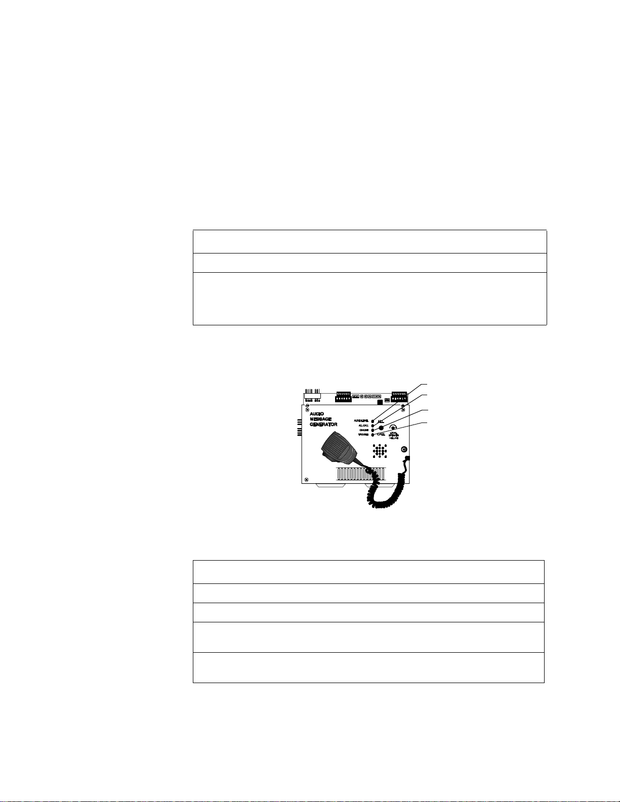
Figure 26 shows the AMG-1 System Status Indicator LEDs:
Audio Level
All Call
On Line
Trouble
Figure 26 AMG-1 LEDs
Table 20 lists descriptions of the AMG-1 LEDs:
LED Lights...
AUDIO LEVEL When the audio level is correct.
ALL CALL Toggles on or off each time you press the All Call switch.
ON LINE To show communication between the control panel and the AMG-1
over the EIA-485 communications circuit.
TROUBLE To show a trouble signal in local audio subsystem equipment (AMG-1,
AA-30/AA-100/AA-120, FFT-7/FFT-7S).
Table 20 Description of AMG-1 LEDs
Unimode 400 Operations PN 50709:A 10/20/97 25
Page 30

5. Voice Alarm Systems AMG-1/AMG-EAudio Message Generator
Operating the AMG-1 Figure 27 shows the AMG-1 operating controls:
All Call Switch
Local Speaker
Volume Control
Microphone switch
J1 – tape recorder
input
Figure 27 AMG-1 Operating Components
Table 21 contains instructions for operating the AMG-1.
To Do this... Comments
Turn on speakers Toggle the ALL CALL switch
until the ALL CALL LED goes
on.
Turn off speakers Toggle the ALL CALL switch
until the ALL CALL LED goes
off.
Adjust the volume
of the AMG-1
Turn the Local Speaker Volume
Control knob.
speaker
Page through the
system
1. Press the ALL CALL
switch.
2. Press the switch on the
side of microphone.
3. Speak into the
microphone.
Select the speaker
circuit for paging
Select the control switches on
the respective VCM-4 module
connected to the AMG-1.
Table 21 AMG-1 Operating Instructions
The ALL CALL switch activates all
speaker circuits (that are not switch
inhibited) or a specific programmed
group of speakers. For dual-channel
applications, press either ALL
CALL switch.
If an alarm exists, speaker circuits
remain on until you turn them off or
reset the system.
If necessary, turn the volume down
to prevent feedback during paging.
Talk loudly enough to cause the
green Audio Level LED to light.If
the AUDIO LEVEL LED remains
off for 15 seconds, a system trouble
can result.
Refer to the Unimode400
Installation and Programming
Manuals for instructions.
26 Unimode 400 Operations PN 50709:A 10/20/97
Page 31

Selecting AMG Group Functions 5. Voice Alarm Systems
Selecting AMG Group Functions
Selecting Factory-Programmed Messages (VROM) Operation of tones and
messages available in a voice alarm application depends on the following:
• The type and number of VROM chips installed; and
• The functional groups selected by AMG-1 DIP switch settings.
Note: If a digitally-stored voice
message fails, the AMG-1
automatically switches to the
primary evacuation tone, and
generates a trouble signal.
Installing one or two optional VROMs lets you select a factory-programmed message
by setting rocker switches 6, 7, and 8 on the AMG-1. (Refer to Selecting AMG Tones
and Messages.) For example, Figure 28 on page 27 shows the text of factory-recorded
VROM-101 message in a male voice:
“MAY I HAVE YOUR ATTENTION PLEASE. MAY I HAVE YOUR ATTENTION PLEASE. THERE HAS
BEEN A FIRE REPORTED ON YOUR FLOOR. THERE HAS BEEN A FIRE REPORTED ON YOUR
FLOOR. PLEASE PROCEED TO THE STAIRWAYS AND EXIT THE BUILDING. DO NOT USE THE
ELEVATORS.”
Figure 28 Sample VROM-101 Message
Refer to Document 15945 for a complete description of all VROM Series messages.
Note: A VRAM message can be
up to 24 seconds long.
VRAM-A Enable
(if installed)
Recording Custom Messages (VRAM option) You can record custom messages
through the AMG-1 microphone or load a message recorded on an audio cassette
recorder. To do so, you must install at least one VRAM chip in U12 (VRAM-A) or U13
(VRAM-B) on the AMG-1 (Figure 29). For example, if the AMG-1 contains a
VRAM-A chip in U12, record a message as follows:
1. If loading a message from a tape recorder, connect the tape recorder to J1 on the
AMG-1. (Figure 29)
2. Set the Voice RAM Enable rocker switch 4 (VRAM-A) or 5 (VRAM-B) on the
AMG DIP Switch (SW2) to the ON position. The AMG-1 starts to record input to
VRAM-A or VRAM-B from a tape recorder or from the AMG-1 microphone.
3. Record a message through the AMG-1 microphone or load a message from a tape
recorder connected to J1.
4. When finished recording or loading the message, set the Voice RAM Enable switch
to the OFF position.
Figure 29 shows the location of connectors and chips on the AMG-1:
Microphone
connector
AMG DIP Switch(SW2)
Connector J1 for tape
recorder input cable
VRAM-B Enable
(if installed)
AMG DIP Switch (SW2) for
loading custom messages.
Optional Voice Message 1
Fact.-programmed (VROM-A)
Optional Voice Message 2
Fact.-programmed (VROM-B)
Optional Voice Message 2
User-programmed (VRAM-B)
Optional Voice Message 1
User-programmed (VRAM-A)
Figure 29 AMG-1 PC Board
Unimode 400 Operations PN 50709:A 10/20/97 27
Page 32

5. Voice Alarm Systems Selecting AMG Tones and Messages
Selecting AMG Tones and Messages
Note: Refer to Appendix A,
Annunciators in the
Unimode400 Installation
Manual for detailed instructions
on using an AMG-1 in ACS
mode. For programming
instructions, refer to the
Unimode400 Programming
Manual.
Overview You can select AMG tones and messages by setting AMG DIP switches. An
AMG appears as an annunciator to the system and operates on annunciator address01.
Operating an AMG, therefore, affects control panel programming and annunciator
switch settings.
1. Select ACS=Y in the System Function screen (Figure 30):
SIL INH=000 AUTO=000 VERIFY=00 USA TIME
TERM_SUPERV=NO LocT BLINK=Y ST=4 ACS=Y
Toggle between N (default) or Y
Figure 30 System Function Screen
2. Enter Annunciator Selection Group 1 for Annunciator Address 1(Figure 31):
Annunciator Address 1
ANNUN SELECTION1: A1=1 A2=* A3=* A4=*
A5=* A6=* A7=* A8=* A9=* A10=* UDACT=Y
Figure 31 Annunciator Selection Screen
Annunciator Selection Group 1
Setting the AMG DIP Switch (SW2) Set the rocker switches on the AMG DIP Switch
(SW2) as follows:
• To set a switch on, push the rocker switch to On.
• To set Message Select switches, refer to Table 23 or Table 24. For example, if you
set switch 2 to Off, refer to the settings in Table 23 for setting switches 6-8.
Switch Number On Off
1 – Low level Audio Four-wire supervision of Low
Level Audio.
2 – Tone/Message select
3 – Receive Only Disables the AMG All Call
4 – Voice RAM Enable A Record a message in VRAM-A Disabled
5 – Voice RAM Enable B Record a message in VRAM-B Disabled
6 – Message Select
7 – Message Select
8 – Message Select
Refer to
switches 6-8
function.
See
See
See
Table 23 for setting
Table 23 or Table 24 for settings.
Table 23 or Table 24 for settings.
Table 23 or Table 24 for settings.
Disabled
Refer to Table 24 for
setting switches 6-8
Disabled
Table 22 AMG DIP SW2 Rocker Switch Settings
28 Unimode 400 Operations PN 50709:A 10/20/97
Page 33

Selecting AMG Tones and Messages 5. Voice Alarm Systems
AMG-1 and AMG-E Tone/Message Selections (AMG-1 SW2=Off) Table 23 lists
the tone and message selections available when SW2 rocker switch2 (Tone/Message
Switch) is Off.
AMG-1 SW2 Rocker
Switches
System
Status
NAC 1 (B01)
Condition
S6 S7 S8
X X X No Alarm Off Standby
Off
Off
Off
Off
Off
Off
Off
Off
OffOnOn
Off
OffOnOn
Off
OffOnOnOnOn
On
Off
On
Off
On
Off
On
OffOOn
On
OnOnOff
On
On
OnOnOnOnNo Alarm
On
X = Indicates that switch or control point can be On or Off.
Off
Off
Off
Off
Off
Off
No Alarm
Alarm
No Alarm
Alarm
No Alarm
Alarm
No Alarm
Alarm
No Alarm
Alarm
No Alarm
Alarm
No Alarm
Alarm
Alarm
On
X
On
X
On
X
On
X
On
X
On
X
On
X
On
X
1000 Hz 0.5 sec on, 0.5 sec off
Slow whoop
Horn
120 ppm (March Time)
Horn
Yelp
Yelp
Wail
3 slow whoops, VRAM-B plays
3 slow whoops, VRAM-A plays
VROM-B message plays VROM-A
message plays
20 ppm (Two-Stage) VROM-A and
VROM-B play
Horn
NFPA Uniform Code 3
Temporal pattern fast whoop
Audio Tone or Message
Table 23 Setting AMG Tones and Messages (AMG-1 SW2=Off)
1. MPS-400 Notification Appliance Circuit 1 (NAC1) can be manually selected with
an ADT-ACM16AT to produce a desired tone or can be activated through Controlby-Event by a non-alarm input.
2. If selecting a VROM or VRAM, and a VROM or VRAM chip is not installed, a
trouble indication appears at the AMG-1 when the message is due to begin and the
AMG-1 generates the 1 kHz default tone.
Unimode 400 Operations PN 50709:A 10/20/97 29
Page 34

5. Voice Alarm Systems Selecting AMG Tones and Messages
AMG-1 and AMG-E Tone/Message Selections (AMG-1 SW2=On) Table 24 lists
the tone and message selections available when SW2 rocker switch 2 (Tone/Message
Switch) is On.
AMG-1 SW2 Rocker
Switches
System
Status
NAC 1 (B01)
Condition
S6 S7 S8
X X X No Alarm Off Standby
Off
Off
Off
Off
Off
Off
Off
Off
Off
Off
Off
Off
Off
On
On
On
On
On
On
Off
Off
Off
Off
On
On
On
On
On
On
Off
Off
Off
Off
Off
Off
Off
On
On
On
Off
Off
Off
On
On
On
Off
Off
Off
On
On
On
No Alarm
Alarm
No Alarm
Alarm
Alarm
No Alarm
Alarm
Alarm
No Alarm
Alarm
Alarm
No Alarm
Alarm
Alarm
No Alarm
Alarm
Alarm
On
Off
On
Off
On
On
Off
On
On
Off
On
On
Off
On
On
Off
On
Horn1000 Hz 1/2 sec on, 1/2 sec off for
5min. then slow whoop
Horn
20 ppm for 5 min., then 120 ppm
120 ppm (March Time)
VROM-B
444, pause, VROM-A
Boston Code
VROM-B
Fast whoop
3 fast whoops, pause, VROM-A
Beep
Fast whoop
3 fast whoops, pause, VROM-A and
VROM-B
Beep
3 slow whoops, pause, VROM-A
3 slow whoops, pause, VROM-A and
VROM-B
Audio Tone or Message
On
On
Off
On
On
On
On
On
On
On
On
On
On
X = Indicates that Switch or Control Point can be On or Off.
Off
Off
On
On
On
No Alarm
Alarm
Alarm
No Alarm
Alarm
Alarm
On
Off
On
On
Off
On
Wail
3 hi-low tones, pause, VROM-A
3 hi-low, pause, VROM-A and VROM-B
Hi-low
20 ppm (Two-Stage)
3 Slow whoops, pause, VROM-A
Table 24 Setting AMG Tones and Messages (AMG-1 SW2=On)
1. You can manually select MPS-400 Notification Appliance Circuit 1 (NAC1) with an
ADT-ACM-16AT to produce a desired tone or it can be activated through Controlby-Event by a non-alarm input.
2. If selecting a VROM or VRAM that is not installed, a trouble will be generated at
the AMG-1 and the AMG-1 generates the 1 kHz default tone.
3. Boston Code (order VROM-109, which must be installed in VROM-B position) –
900 Hz alert tone pulsed to produce one round of code 4 at approximately one
second intervals, followed by female voice message:
“Attention please. The signal tone you have just heard indicates a report of an emergency in this
building. If your floor evacuation signal sounds after this message, walk to the nearest stairway and leave
the floor. While the report is being verified, occupants on other floors should await further instructions.”
This message repeats. The evacuation signal is a slow-whoop tone—an ascending
tone that starts at approximately 600 Hz and ends at approximately1100 Hz—with
a duration of approximately 3.5 seconds and an interruption between tones of
approximately 0.5 second.
30 Unimode 400 Operations PN 50709:A 10/20/97
Page 35

ATG-2 Audio Tone Generator 5. Voice Alarm Systems
ATG-2 Audio Tone Generator
ATG-2 Overview The ATG-2 provides user-selected tones for single or dual channel output. The ATG-2
provides several ways to page.
• Direct paging – The ATG-2 microphone with a button switch lets you page through
primary and secondary speaker circuits channels. If used with an optional FFT-7,
the ATG-2 also lets you page through the system from telephones installed
throughout the installation.
Note: For more information on
ATG-2 configuration, refer to
the Voice Modules Section of
the Unimode400 Installation
Manual.
• Remote paging microphone – You can also set up the ATG-2 to pass-through an
audio message (or tone) received from an AMG-1 or another ATG-2. In this
configuration, the ATG-2 serves as an alternate (remote) paging location for the
AMG-1 or main ATG-2. The ATG-2 provides override paging capabilities from the
ATG-2 microphone. All communications go through NAC 1 using ACS mode
(Refer to the Unimode400 Installation Manual for instructions.) connected to the
control panel—unless set up for remote paging microphone operation.
Figure 32 shows the operating features of the ATG-2:
Microphone
Switch
Built-in Microphone
Page Select switch – lets you page through
speaker circuits on one, two, or both channels.
Primary (Evac) channel – slow whoop, Hi/Lo,
or steady tone
Secondary (Alert) channel (dual channel) – a
chime or a 20pulses-per-minute tone.
System Status
Indicator LEDs
Figure 32 Operating Features of the ATG-2
Table 25 contains descriptions of the four System Status Indicator LEDs:
LED Color Lights to show...
ON LINE LED green Control panel communication with the ATG-2.
EVAC CHANNEL green Paging will take place over the Primary (Evac)
channel.
ALERT CHANNEL green Paging will take place over the Secondary (Alert)
channel.
TROUBLE LED yellow A trouble in local audio subsystem equipment
(AMG-1, AA-30, FFT-7).
Table 25 ATG-2 LEDs
Unimode 400 Operations PN 50709:A 10/20/97 31
Page 36

5. Voice Alarm Systems ATG-2 Audio Tone Generator
How to Operate the
ATG-2
Selecting Tones for the
ATG-2
Table 26 contains instructions for operating the ATG-2.
To... Do this...
Select the paging channel Press the Evac Channel switch to select the Evacuation
(Primary) channel; or press the Alert Channel switch to
select the Alert (Secondary) channel.
Page Select Switch – Push until the
LED on the selected channel lights
Verify the active channel Check the Evac Channel and Alert Channel LEDs.
Page Press the microphone switch and speak into the
microphone (loudly enough to light the green On Line
LED).
Table 26 Operating the ATG-2
The ATG-2 DIP switch—S1 located on the ATG-2 board shown in Figure 33—provides
rocker switches for selecting output tones and setting operations. When finished setting
rocker switches, check the ATG-2 for proper operation. Figure 33 shows the ATG-2
board layout and identifies DIP S1:
DIP Switch S1 for
configuring the
ATG-2
Figure 33 ATG-2 Board Components
32 Unimode 400 Operations PN 50709:A 10/20/97
Page 37

ATG-2 Audio Tone Generator 5. Voice Alarm Systems
Figure 34 shows the functions of the ATG-2 DIP switch pins:
Select Primary (EVAC) channel tones.
Select to use the ATG-2 in a remote paging application.
Select to use the ATG-2 as the main paging/tone generator.
Select Secondary (ALERT) channel tones.
Figure 34 ATG-2 DIP Switch S1
Selecting a Primary
(Evac) Channel Tone
Selecting a Secondary
(Alert) Channel Tone
Switch S1 rocker switches 1–4 are used to select one of the following tones: slow
whoop, Hi/Lo, or steady tone. Select a tone by setting rocker switches as shown in
Table 27:
DIP Switch Whoop Hi/Lo Steady
1 Off On On
2 On Off Off
3 On On Off
4 Off On Off
Table 27 Evacuation Tone Settings
The ATG-2 can produce a chime or a 20 pulses-per-minute tone on the secondary
(Alert) channel. To select tones for the secondary channel, set S1 rocker switches 7 and
8 in one of the combinations shown in Table 28:
DIP Switch Chime 20 PPM
1 Off On
2 On Off
Table 28 Secondary (Alert) Tone Settings
Select Operating Mode You can set the ATG-2 for one of two modes of operation: 1) remote paging only; or 2)
tone generation and paging capability. Set S1 rocker switches 5 and 6 as shown in Table
29. After setting rocker switches, test the ATG-2 for proper operation.
DIP Switch Remote Paging Only Paging and Tone Generate
5 On Off
6 Off On
Table 29 Operation Mode Settings
Unimode 400 Operations PN 50709:A 10/20/97 33
Page 38

5. Voice Alarm Systems Fire Fighter's Telephones (FFT-7/FFT-7S)
Fire Fighter's Telephones (FFT-7/FFT-7S)
Overview A Fire Fighter's Telephone provides the Voice Alarm System with fire-fighter control of
paging, and two-way communications in an emergency situation. Connect the FFT-7 to
an Audio Message Generator (AMG-1) or Audio Tone Generator (ATG-2). Up to seven
telephones can converse at the same time. Fire Fighter's Telephones come in two
models:
FFT-7 – provides full capability including paging.
FFT-7S – provides same features as the FFT-7, without paging capabilities.
Page Mode LED
On Line LED
Line Trouble LED
IN E
Phone Trouble LED
Page Button (not on FFT-7S)
Telephone Handset
A
UDIOAMG
P
AGE M ODE
O
F
IRE
FIGHTERS
TELEPHONE
P
A G E
P
H ON E
TR O U B LE
N L I N E
L
TR OU B LE
Figure 35 FFT-7 Telephone Operating Components
FFT-7 Operating
Components
How to Operate the
FFT-7
Note: An FFT-7 will not
operate unless:
• power is connected to the
FFT-7;
• the AMG-1/FFT-7 control
harness is connected
between the AMG-1 and
the FFT-7; and
• the AMG-1 is set up for
EIA-485 communication
through the CPU ACS port
(TB4).
Refer to the Unimode400
Installation Manual for
instructions on making these
connections.
Table 30 contains descriptions of the FFT-7 LED indicators and Page button:
Component Function
Page Mode LED Toggles on or off when you press the Page button.
On Line LED Lights continuously to indicate the FFT-7 is receiving power.
Page Button Press the Page button to initiate a page (FFT-7 only).
Line Trouble LED Lights to indicate a trouble exists on another device with trouble
contacts wired to the FFT-7 trouble input connector.
Phone Trouble LED Lights to indicate a trouble exists on the FFT-7.
Table 30 Description of FFT-7 Operating Components
Paging Operation
To page over the FFT-7, follow these instructions:
1. Make sure the On Line green LED is on; then, pick up the telephone handset.
2. Press the Page button (the Page Mode green LED goes on) and speak into the
telephone handset.
When finished paging, press the Page button (the Page Mode green LED goes out) and
hang up the telephone handset.
Two-Way Conversation
To answer a call with an FFT-7, follow these instructions:
1. When the VCM-4 sounder produces a steady tone and the telephone circuit green
LED goes on, pick up the telephone handset and speak into the telephone headset.
2. When finished with the conversation, hang up the telephone handset.
34 Unimode 400 Operations PN 50709:A 10/20/97
Page 39

Audio Amplifiers 5. Voice Alarm Systems
Audio Amplifiers
Overview Audio Amplifiers provide audio power for the Voice Audio System. The control panel
supports three models of audio amplifiers as listed in Table 31:
Amplifier Audio Power Speaker Circuits
Audio Amplifier
Features
AA-30
See Figure 36 on page 36
AA-100
See Figure 37 on page 37
AA-120
See Figure 37 on page 37
30 watts – compatible with
25Vrms speakers.
100 watts of 70.7Vrms audio. up to 100 watts each.
120 watts of 25Vrms audio. up to 120 watts each.
up to 30 watts each.
Table 31 Audio Amplifier Models
Audio amplifiers provide the following features:
Built-in Supervision Each audio amplifier contains a set of normally-open
•
trouble contacts that close to light an LED showing the type of trouble. Types of
trouble include: brownout, loss of low-level supervision tone at the input, battery
failure, audio output wiring failure (if set for four-wire output), and amplifier
failure. During total loss of primary AC power, all LEDs extinguish to conserve
battery power.
Backup You can set up an audio amplifier as a backup amplifier for multiple
•
amplifiers. If an amplifier fails, the control panel automatically switches to the
backup amplifier.
Speaker zone selection Set by control-by-event or set manually using control
•
switches on the VCM-4, DCM-4, or ADT-ACM-16AT modules.
Unimode 400 Operations PN 50709:A 10/20/97 35
Page 40

5. Voice Alarm Systems AA-30 Audio Amplifiers
AA-30 Audio Amplifiers
Note: For instructions on setting
the Audio Gain Rotary Switch,
refer to “Adjusting the Audio
Gain Level (AA-30, AA-100/AA-
120)” on page 38.
Figure 36 shows the layout of the AA-30 circuit board and identifies AA-30
components:
Audio Gain Rotary Switch
Normal Level LED
Incorrect Level LED
Figure 36 AA-30 Circuit Board
Speaker Trouble LED
Amplifier Trouble LED
Battery Trouble LED
Brownout LED
Table 32 lists the conditions that cause each AA-30 System Status Indicator LED to
light:
LED Lights when...
Normal Level The audio amplifier is adjusted properly and operating correctly
during normal (non-alarm) conditions.
Incorrect Level The audio amplifier is out of adjustment during normal (non-alarm)
conditions.
Speaker Trouble An open circuit condition occurs in the four-wire, high-level output.
Amplifier Trouble A loss of the low-level audio input signal, or an amplifier failure.
Battery Trouble The battery voltage is below a sufficient level.
Brownout The AC power source is below a sufficient level. During a complete
loss of AC power, no LEDs will light on the AA-30.
Table 32 AA-30 Components
Notes:
1. The amplifier does not indicate a trouble condition until 40 seconds after these
faults occur.
2. To calibrate audio amplifiers, install a 470-ohm resistor at the end of the low-level
audio circuit. If the low-level audio circuit is configured as four wire circuit, install
a 470-ohm resistor at the point furthest from the AMG-1 or ATG-2.
36 Unimode 400 Operations PN 50709:A 10/20/97
Page 41

AA-100/AA-120 Audio Amplifiers 5. Voice Alarm Systems
AA-100/AA-120 Audio Amplifiers
Figure 37 shows the AA-100/AA-120 circuit board and identifies key components:
Normal Level LED
Incorrect Level LED
Audio Gain Rotary Switch (Refer to “ Adjusting
the Audio Gain Level (AA-30, AA-100/AA-
120)” on page 38)
Figure 37 AA-100/AA-120 Circuit Board
LED Lights when...
Normal Level The audio amplifier is adjusted properly and operating correctly
during normal (non-alarm) conditions.
Incorrect Level The audio amplifier is out of adjustment during normal (non-alarm)
conditions.
Battery Trouble The battery voltage is below a sufficient level.
Brownout The AC power source is below a sufficient level. During a complete
loss of AC power, no LEDs will light on the AA-100/AA-120.
Speaker Trouble An open circuit condition occurs in the four-wire, high-level output.
Input Trouble A loss of the low-level audio input signal, or an amplifier failure.
(see note below)
SW1 – Backup tone (Refer to “Selecting the
AA-100/AA-120 Backup Tone” on page 38)
Battery Trouble LED
Brownout LED
Speaker Trouble LED
Input Trouble LED
Amplifier Trouble LED
Amplifier Trouble A loss of the low-level audio input signal, or an amplifier failure.
(see note 3 below)
Table 33 AA-100/AA-120 Indicators
Notes:
1. During complete loss of primary (AC) power, the AA-100/AA-120 operates on
secondary (battery) power. To conserve secondary power, no LEDs light on the
AA-100/AA-120 while operating on batteries.
2. An audio amplifier does not indicate a trouble condition until 40 seconds after a
fault occurs.
3. To calibrate audio amplifiers, install a 470-ohm resistor at the end of the low-level
audio circuit. If the low-level audio circuit is configured as four wire circuit, install
a 470-ohm resistor at the point furthest from the AMG-1 or ATG-2.
Unimode 400 Operations PN 50709:A 10/20/97 37
Page 42

5. Voice Alarm Systems Adjusting the Audio Gain Level (AA-30, AA-100/AA-120)
Adjusting the Audio Gain Level (AA-30, AA-100/AA-120)
An audio amplifier contains a multi-position rotary switch that lets you adjust the gain
of the audio output signal. This adjustment compensates for audio line losses. After
correct adjustment, an audio amplifier can produce its maximum rated output power of
25 Vrms (AA-30, AA-120) or 70.7Vrms (AA-100). Refer to Figure 37 on page 37 for
the location of the Audio Gain Rotary Switch.
Audio Gain Rotary Switch
(See Figure 37 on page 37
for location of switch.)
When finished installing all amplifiers and associated circuitry, adjust the audio gain as
follows:
1. Locate the Audio Gain Rotary Switch on the AA-30 (Figure 36) or the AA-100/
AA-120 (Figure 37).
2. Use a small slotted screwdriver to turn the Audio Gain Rotary Switch until the
Normal Level LED and Incorrect Level LED are properly adjusted as shown in
Table 34:
!
Audio Level Normal Level LED Incorrect Level LED
Caution: Remove AC
power at the main service
circuit breaker (not the
circuit breaker on the main
power supply).
Properly adjusted
Adjusted too low
Adjusted too high
★ ✩
✩ ★
★ ★
LED on ✩ LED off
★
Table 34 Adjusting the AA-30/AA-100/AA-120 Audio Level
Selecting the AA-100/AA-120 Backup Tone
An audio amplifier automatically produces a backup tone when the low-level audio
input is lost. You can select the backup tone by following these steps.
1. Locate SW1 in the lower right-hand corner of the AA-100/AA-120 circuit board
(See Figure 37 on page 37).
2. Set SW1 to Hi/Lo or Slow Whoop as the default backup tone (Figure 38).
Hi/Lo
Figure 38 LSW1 Backup Tone Switch (AA-100/AA-120 only)
Slow Whoop
38 Unimode 400 Operations PN 50709:A 10/20/97
Page 43

AMG Voice Message Options 5. Voice Alarm Systems
AMG Voice Message Options
Overview You can install two types of non-memory message chips into an AMG:
VROM (Voice ROM) A nonvolatile memory chip that contains a factory-programmed
message. (An AMG can hold two VROMs: VROM-A and VROM-B.) A VROM
provides one evacuation message (up to 24 seconds long), chosen from many standard
messages available. Refer to Document 15945 for a list of available VROMs.
VRAM-1 (Voice RAM) A nonvolatile memory chip for a field-programmed memory
message. A VRAM-1 provides one field-programmable evacuation message (up to 24
seconds long), programmed from microphone or cassette tape. An AMG can hold up to
two VRAM-1 chips.
Installation To install a VROM or VRAM, follow these steps:
1. Remove battery power, then remove AC power from the control panel.
2. Remove the four screws that hold the AMG dress plate to the component board.
3. Remove the dress plate and disconnect the microphone connector.
4. Install the VROM or VRAM chips in their respective sockets as shown below.
5. Connect the microphone cable and install the AMG dress panel.
When finished installing VROM or VRAM chips, assemble the AMG by following
these instructions in reverse. Figure 39 shows the location of the VROM and VRAM
chips on the AMG-1:
AMG DIP Switch(SW2)
Optional Voice Message 1
Fact.-programmed (VROM-A)
Figure 39 Location of VROM and VRAM on the AMG-1
Optional Voice Message 2
Fact.-programmed (VROM-B)
Connector J1 for tape
recorder input cable
Microphone
connector
Optional Voice Message 2
User-programmed (VRAM-B)
Optional Voice Message 1
User-programmed (VRAM-A)
Unimode 400 Operations PN 50709:A 10/20/97 39
Page 44

Notes
40 Unimode 400 Operations PN 50709:A 10/20/97
 Loading...