

Page 1
61200373L1-5B
Issue 2, August 2001
CLEI Code: SIUXJKEBAA
Total AccessTM 850 Bank Controller Unit Installation and Operation
Contents
1. GENERAL ..................................................................... 1
2. INSTALLATION/OPERATION................................ 1
3. OPTIONS....................................................................... 2
4. TESTING........................................................................ 3
5. SPECIFICATIONS........................................................ 5
6. MAINTENANCE ......................................................... 5
7. WARRANTY AND CUSTOMER SERVICE............. 5
8. LIMITED PRODUCT WARRANTY .......................... 6
9. REGULATORY REQUIREMENTS ............................ 6
Figures
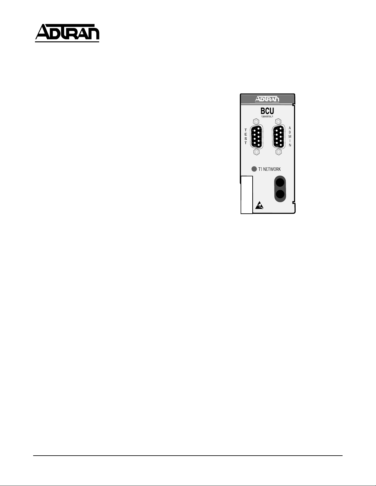
Figure 1. TA 850 BCU ...................................................... 1
Figure 2. Bantam Jack Monitoring Points ..................... 3
Figure 3. DB-9 Connector Pinout ................................... 5
Tables
Table 1. Pinout Connectors for RJ-48 T1 Interface....... 3
Table 2. LED Indication ................................................... 3
Table 3. DIP Switch S1 Options...................................... 4
Table 4. Specifications...................................................... 5
1. GENERAL
This practice provides installation and operation procedures for the ADTRAN TA 850 Bank Controller Unit
(BCU) common module, List 1. The TA 850 BCU module is designed specifically for the ADTRAN Total Access 850 and is not used in any other product. Figure 1
is an illustration of the TA 850 BCU.
Revision History
This is the initial release of this document. Future revisions to this document will be explained in this subsection.
Features
The TA 850 BCU, part number 1200373L1, includes the
following features:
• Controls all common equipment and access modules.
• T1 network termination.
• Built-in Channel Service Unit (CSU).
• Provides VT 100 craft interface via faceplate DB-9
connector.
• Bantam Jacks provide access to Network T1.
• LED network status indication.
• T1 performance monitoring.
• Supports TR-08 signaling.
• NEBS Level 3 and UL 1950 compliant.
•
DS1
TX
M
O
N
RX
TX
M
O
N
RX
DS1
Figure 1. TA 850 BCU
General Description
The TA 850 BCU is a common module plug-in unit designed for the TA 850. The BCU, with a built-in CSU,
provides all control functions for the TA 850 common
units and all individual access modules. A faceplate
ADMIN DB-9 provides access for a VT100 terminal for
screen menu provisioning, and bantam test jacks provide transmit and receive monitoring. An additional
TEST DB-9 provides timing for DS0 test equipment. A
network LED shows status information for the network
T1. The unit comprises a main circuit board and daughter card and inserts directly into the BCU slot on the TA
850 shelf. An 8-position DIP switch is mounted on the
daughter card and is used for T1 provisioning and
clocking.
Functional Description
The TA 850 BCU provisions, operates, monitors, and
tests all TA 850 access modules including Quad FXS,
Quad FXO, OCU DP, DS0 DP, and Nx56/64 DSU DP.
The BCU programs T1 bandwidth use between the various access modules and data ports.
2. INSTALLATION/OPERATION
After unpacking the unit, inspect it for damage. If damage is noted, file a claim with the carrier, then notify
ADTRAN Customer Service (see “WARRANTY AND
CUSTOMER SERVICE” on page 5).
61200373L1-5B 1
Trademarks: Any brand names and product names included in this document are
trademarks, registered trademarks, or trade names of their respective holders.
Page 2

The TA 850 BCU plugs directly into the controller slot
in the common module area of the TA 850 chassis. To
insert, hold the unit by the faceplate while supporting
the bottom side. Align the card edges to the guide
grooves for the designated slot. Insert into the chassis
until the edge connector seats firmly into the backplane.
Lock the unit in place by pushing in on the locking lever.
CAUTION
This product is intended for installation in Restricted Access Locations only and is intended to be
installed in equipment with a Type "B" or "E" installation code.
3. OPTIONS
The TA 850 BCU can be provisioned from either an 8-position Dual In-line Package (DIP) switch (S1) mounted on
the PCB, or through screen menus accessed via the faceplate craft interface port. Basic T1 provisioning, clock
source, and CSU loopback options are found on the DIP
switch. Refer to Table 3 on page 4 for DIP switch S1 pro-
visioning information. Additional and more in-depth
provisioning options for the BCU as well as access modules are available through the craft ADMIN interface.
DIP switch S1 must be provisioned while the BCU is
withdrawn from the chassis. Once installed, any software provisioning made will override the DIP switch
settings. If the unit is withdrawn and reinserted (power
cycled), the software options remain in effect. If a DIP
switch setting is changed while withdrawn, the new
DIP switch setting takes effect. If none of the DIP switch
settings were changed, the unit will be provisioned for
the last software settings.
Electronic Provisioning
The ADMIN interface on the TA 850 BCU is used to
change factory selected options and obtain access module status through menu screens. To access the menu
screens, connect a VT 100 terminal or computer running
a terminal emulation program to the craft interface port
using a standard male-to-male RS-232 DB-9 cable. Craft
port settings are as follows:
• 9600 Baud
•No parity
•8 Data bits
•1 Stop bit
CAUTION
The BCU retains provisioning setup when removed from the chassis. If inserted into another
chassis, the provisioning setup is invoked on that
chassis' access modules.
Windows Hyperterminal. Windows Hyperterminal
can be used as a VT 100 terminal emulation program.
Open Hyperterminal by selecting PROGRAMS / ACCESSORIES / HYPERTERMINAL. Refer to the Help
section of Hyperterminal for additional questions.
NOTE
To ensure proper display background in Windows
Hyperterminal, select VT 100 terminal emulation
under SETTINGS.
Password. When connected, enter the password. The
factory default is PASSWORD in all capital letters. The
password can be changed to a user selected password
once connected.
Menu Navigation. To traverse through the menus, se-
lect the desired entry and press Enter. To work backwards in the menu, press the Esc (escape) key.
Time Slot Assignment (Plug and Play Environment). The TA 850 can support a plug and play envi-
ronment for slots 1-6 of the TA 850 bank for the various
access modules (i.e., FXS, FXO, OCU DP, DSO DP,
UBRITE, E&M, etc.). Each card that is plugged in to
slots 1-6 will consecutively take 4 Time Slots automatically when installed in the TA 850 bank, depending on
the card that is plugged into the shelf.
Time Slot Assignment - Software Assignment
(Non-Plug and Play Environment). Slots 1-6 of the TA
850 Bank are for the various access modules supported
by the the TA 850 (i.e., FXS, FXO, OCU DP, DSO DP,
UBRITE, E&M, etc.). The T1 interface on the TA 850
BCU supports 24 Time Slot Assignment which can be
allocated to the access modules, to the DSX-1, or to the
Nx64 module. The TA 850 BCU can override the plug
and play assignments through the software menus via
the ADMIN port on the TA 850 BCU.
Slot Time Slot
1 1-4 FXS, FXO, OCU DP, DSO DP,
2 5-8 FXS, FXO, OCU DP, DSO DP,
3 9-12 FXS, FXO, OCU DP, DSO DP,
4 13-16 FXS, FXO, OCU DP, DSO DP,
5 17-20 FXS, FXO, OCU DP, DSO DP,
6 21-24 FXS, FXO, OCU DP, DSO DP,
A/B
(special
slot)
BCU 1-24 BCU or BCU w/DSX-1
Available
UBRITE, E&M, etc.
UBRITE, E&M, etc.
UBRITE, E&M, etc.
UBRITE, E&M, etc.
UBRITE, E&M, etc.
UBRITE, E&M, etc.
1-24 Nx56/64
Access Module
2 Issue 2, August 2001 61200373L1-5B
Page 3
Access
Module
Maximum Number of DS0s that can
be used per m odule
FXS 4
FXO 4
*OCU-DP 1
*DSO-DP 1
*U-BRITE 1
*E&M 1
Nx56/64
24
(special slot)
*Supported in TA 850 Q300.
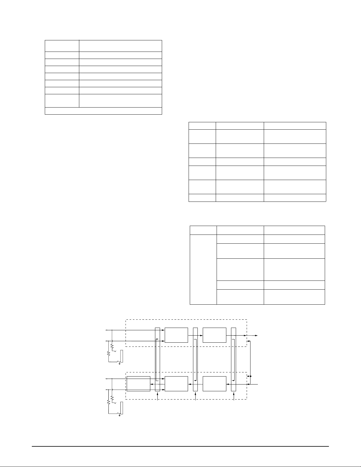
Figure 2 on page 3 displays where the bantam jacks
monitor the T1.
Faceplate TEST connector
The faceplate DB-9 female TEST connector provides the
necessary clock output required by standard DSO Logic
Test equipment such as a TPI 108/109 test set. Specifically, the TEST connector outputs 8 kHz and 64 kHz
clock reference signal. Figure 3 on page 5 illustrates the
DB-9 TEST connector.
Table 1. Pinout Connectors for RJ-48 T1 Interface
Connections
All TA 850 BCU connections are made through the
backplane connector. With the exception of power and
the V.35 connector, all of the TA 850 rear panel connectors terminate on the BCU. These include Network T1,
Clock source, Alarms, Fractional T1, and Management.
Refer to the TA 850 System Installation and Maintenance Practice, part number 64200376L1- 5A, for additional information on rear panel connections. Table 1
describes the T1 pinout connections.
Faceplate LED
The faceplate Network LED labeled T1 Network provides status information for the network T1 using a color coded message format. Refer to Table 2.
4. TESTING
The TA 850 BCU provides a variety of test options for
both the Network T1 and DS0 access modules. The faceplate of the BCU provides a bantam jack for local T1 test
access. DS0 test access for the digital access modules
(OCU DP, DS0 DP, U-BR1TE) is provided via bantam
jacks on the faceplate of each unit.
Faceplate Bantam Jack
The faceplate bantam jack provides a means to monitor
the network T1 connected to the rear of the TA 850 chassis. The jacks accept standard 310-type bantam plugs.
Pin Name Description
1 R1 - RING1 Receive data from
Network DS1
2 T1 - TIP1 Receive data from
Network DS1
3 unused 4 R - RING T ransmit d ata to Network
DS1
5 T - TIP T rans mit data to Network
DS1
6, 7, 8 unused -
Table 2. LED Indication
LED Condition Description
OFF No power.
RED Unit in Red Alarm (T1
Network
T1
YELLOW Receiving Yellow Alarm
GREEN Normal Operation.
FLASHING
GREEN
down or not connected.)
(far end unit in Red
Alarm.)
Network T1 in Test.
Receiver Circuitry
T1
T1
RX
PAIR
T1
TX
PAIR
R1
MON IN
Test Jack
T
R
Equalizer
MON OUT
Test Jack
Clock and Data
Recovery
DJAT
Transmitter Circuitry
Local
Loopback
Point
Line
Loopback
Point
Line Format
Decoder
Line Format
Encoder
Payload/CSU
Loopback
Point
To
Backplane
From
Backplane
Figure 2. Bantam Jack Monitoring Points
61200373L1-5B Issue 2, August 2001 3
Page 4

Table 3. DIP Switch S1 Options
Switch Function Description
S1-1 Framing Format Enables either Extended Superframe Format (ESF) or Superframe
S1-2 Line Code
Format
S1-3 TR-08 Signaling Enables TR-08 signaling optio n. When enabled, S1-1 is ignored.
S1-4 CSU Loopback Enab les the CSU Loop back Functio n. Unit will resp ond to CSU loopba ck
Timing Mode
Format (SF). This op tion m ust be confi gured i dentic ally with al l other T1
network equipment o n this circuit.
On* SF
Off ESF
Enables Bipolar Eight-Zero Substitution (B8ZS), which allows fo r Clear
Channel operation for the T1 carrier system, or enables Alternate Mark
Inversion (AMI). This option mus t be configur ed ident icall y with all other
T1 network equipment on thi s cir cui t.
On* AMI
Off B8ZS
On* Enabled
Off Disabled
sent from a remote ne tw o rk device or test equipment.
Off* Enabled
On Disabled
Determines clock so urce for TA 850.
S1-5
S1-6
S1-7
S1-8
*Denotes fa ctory default s etti ng.
Timing A
Timing B
DS1 Attenuation
LBO A
LBO B
S1-5
Off Off Loop timing: Derives timing from T1
On Off External timing: Derives timing from external BITS
Off On Local timing: Clock gener ated f rom internal timi ng
On* On* Loop timing: Derives timing from T1.
Selects attenuation to set receiver sensitivity in decibels (dB).
S1-7
Off Off 0 dB/0-133 ft (LBO)
On Off -7.5 dB
Off On -15 dB
On* On* -22.5 dB
(Note: Additional LBO settings can be provisioned through the menu
interface.)
S1-6 Function
clock.
source.
S1-8 Setting
4 Issue 2, August 2001 61200373L1-5B
Page 5

TEST
1
6
2
7
3
8
4
9
5
+5 V
GND
64 kHz
8 kHz
Figure 3. DB-9 Connector Pinout
DS0 test equipment is used to test DS0 access modules
such as the OCU DP, DS0 DP, or U-BR1TE. Once the test
equipment is connected to the reference clock source,
individual tests can be performed on DS0 access modules using the faceplate bantam jacks on each unit.
T1 Loopbacks
The TA 850 supports several T1 loopbacks via the craft
interface. These loopbacks include:
• Initiating a remote payload or line loopback command (ESF mode only).
• Responding to a remote payload or line loopback
command (ESF mode only).
• Responding to a remote CSU loopback command.
Figure 2 on page 3 displays where the various loopbacks occur in the TA 850 BCU circuitry.
Self Test
The BCU goes into self test when inserted into an active
TA 850 chassis. The self test checks internal BCU circuitry. A failed test causes the faceplate Network T1 LED to
blink red.
5. SPECIFICATIONS
Refer to Table 4 for TA 850 BCU specifications.
6. MAINTENANCE
The TA 850 BCU does not require routine maintenance
for design operation.
ADTRAN does not recommend that repairs be attempted in the field. Repair services are obtained by returning
the defective unit to ADTRAN Customer Service department.
Flash Upload
The TA 850 BCU can flash upload firmware to the unit
using the front panel VT 100 craft interface. Flash upload is useful for product upgrade or enhancements.
Flash upload procedures are as follows:
1. Obtain firmware, available by diskette or email, from
ADTRAN Customer Service.
2. Connect to the craft interface port using instructions
found in “OPTIONS” on page 2.
3. Once connected, enter the Bank Controller submenu
and select Upload Code.
4. To upload code, select Load new code and follow the
instructions on the screen. The user is offered the
opportunity to increase the baud rate from 9600 to
19.2 K, 38.4 K, or 57.6 K. Be sure that your terminal
device can support a higher speed before selecting.
Also, some terminal emulation packages (such as
Hyperterminal) require that the current session be
disconnected and reconnected after changing from
one baud rate to another.
5. Continue to follow the instructions on the screen,
noting that the TA 850 BCU uses the XMODEM protocol to transfer code.
6. After successfully uploading code, the TA 850 Bank
Controller will reset itself and resume operation.
Table 4. Specifications
ADTRAN will replace or repair this product within 10
years from the date of shipment if it does not meet its
7. WARRANTY AND CUSTOMER SERVICE
Mechanical
Dimensions 1 11/16” W x 3” H x 10” L
Weight 1 lb
Environmental
Operating Tempera t ure
Storage Temperature
Relative Humidity Up to 95%, noncondensing
Configuration Codes
Power Code (PC) IN: F, OUT: C
Telecommunication Code
(TC)
Installation Code (IC) IN: A, OUT: -
61200373L1-5B Issue 2, August 2001 5
-40 to 65
-40 to 85
IN: X, OUT: X
o
C
o
C
published specifications or fails while in service. For detailed warranty, repair, and return information refer to
the ADTRAN Equipment Warranty and Repair and Return Policy Procedure.
Return Material Authorization (RMA) is required prior
to returning equipment to ADTRAN.
For service, RMA requests, or more information, see the
following sections for the correct toll-free contact number.
Page 6

Product Support Information
Pre-Sales Inquiries and Applications Support.
Please contact your local distributor, ADTRAN Applications Engineering, or ADTRAN Sales:
This warranty applies only to the original purchaser and
is not transferable without ADTRAN's express written
permission. This warranty becomes null and void if Customer modifies or alters the equipment in any way, other
than as specifically authorized by ADTRAN.
Applications Engineering (800) 615-1176
Sales (800) 827-0807
Post-Sale Support. Please contact your local distribu-
tor first. If your local distributor cannot help, please
contact ADTRAN Technical Support and have the unit
serial number available.
Technical Support (888) 4ADTRAN
Repair and Return. If ADTRAN Technical Support
determines that a repair is needed, Technical Support
will coordinate with the Customer and Product Service
(CAPS) department to issue an RMA number. For information regarding equipment currently in house or possible fees associated with repair, contact CAPS directly
at the following number:
CAPS Department (256) 963-8722
Identify the RMA number clearly on the package (below address), and return to the following address:
EXCEPT FOR THE LIMITED WARRANTY DESCRIBED
ABOVE, THE FOREGOING CONSTITUTES THE SOLE
AND EXCLUSIVE REMEDY OF THE CUSTOMER
AND THE EXCLUSIVE LIABILITY OF ADTRAN AND
IS IN LIEU OF ANY AND ALL OTHER WARRANTIES
(EXPRESSED OR IMPLIED). ADTRAN SPECIFICALLY
DISCLAIMS ALL OTHER WARRANTIES, INCLUDING (WITHOUT LIMITATION), ALL WARRANTIES
OF MERCHANTABILITY AND FITNESS FOR A PARTICULAR PURPOSE. SOME STATES DO NOT ALLOW THE EXCLUSION OF IMPLIED WARRANTIES,
SO THIS EXCLUSION MAY NOT APPLY TO CUSTOMER.
In no event will ADTRAN or its suppliers be liable to
Customer for any incidental, special, punitive, exemplary or consequential damages experienced by either
Customer or a third party (including, but not limited to,
loss of data or information, loss of profits, or loss of
use). ADTRAN is not liable for damages for any cause
whatsoever (whether based in contract, tort, or otherwise) in excess of the amount paid for the item. Some
states do not allow the limitation or exclusion of liability for incidental or consequential damages, so the above
limitation or exclusion may not apply to Customer.
ADTRAN, Inc.
6767 Old Madison Pike
Progress Center
Building #6 Suite 690
Huntsville, Alabama 35807
RMA # _____________
8. LIMITED PRODUCT WARRANTY
ADTRAN warrants that for ten years from the date of
shipment to Customer, all products manufactured by
ADTRAN will be free from defects in materials and
workmanship. ADTRAN also warrants that products
will conform to the applicable specifications and drawings for such products, as contained in the Product
Manual or in ADTRAN's internal specifications and
drawings for such products (which may or may not be
reflected in the Product Manual). This warranty only
applies if Customer gives ADTRAN written notice of
defects during the warranty period. Upon such notice,
ADTRAN will, at its option, either repair or replace the
defective item. If ADTRAN is unable, in a reasonable
time, to repair or replace any equipment to a condition as
warranted, Customer is entitled to a full refund of the purchase price upon return of the equipment to ADTRAN.
9. REGULATORY REQUIREMENTS
Affidavit Requirements for Connection to Digital
Services
• An affidavit is required to be given to the telephone
company whenever digital terminal equipment without encoded analog content and billing protection is
used to transmit digital signals containing encoded
analog content which are intended for eventual conversion into voiceband analog signals and transmitted on the network.
• The affidavit shall affirm that either no encoded analog content or billing information is being transmitted
or that the output of the device meets Part 68 encoded
analog content or billing protection specifications.
• End user/customer will be responsible for filing an
affidavit with the local exchange carrier when connecting unprotected customer premise equipment
(CPE) to 1.544 Mbps or subrate digital services.
• Until such time as subrate digital terminal equipment
is registered for voice applications, the affidavit requirement for subrate services is waived.
6 Issue 2, August 2001 61200373L1-5B
Page 7

Affidavit for Connection of Customer Premises
Equipment to 1.544 Mbps and/or Subrate Digital
Services
For the work to be performed in the certified territory of
________________________(telco name)
State of ________________
County of ________________
( ) D. In lieu of the preceding training requirements,
the operator(s)/maintainer(s) is (are) under the
control of a supervisor trained in accordance
with _________ (circle one) above.
I agree to provide ______________________ (telco’s
name) with proper documentation to demonstrate compliance with the information as provided in the preceding paragraph, if so requested.
I, _____________________________ (name),
__________________________________(business address),
____________________ (telephone number) being duly
sworn, state:
I have responsibility for the operation and maintenance
of the terminal equipment to be connected to 1.544
Mbps and/or ________ subrate digital services. The terminal equipment to be connected complies with Part 68
of the FCC rules except for the encoded analog content
and billing protection specifications. With respect to encoded analog content and billing protection:
( ) I attest that all operations associated with the
establishment, maintenance, and adjustment of the
digital CPE with respect to analog content and
encoded billing protection information continuously complies with Part 68 of the FCC Rules and
Regulations.
( ) The digital CPE does not transmit digital signals
containing encoded analog content or billing information which is intended to be decoded within the
telecommunications network.
_________________________________Signature
_________________________________Title
_________________________________ Date
Transcribed and sworn to before me
This ________ day of ________, ________
_________________________________
Notary Public
My commission expires:
_________________________________
( ) The encoded analog content and billing protection is
factory set and is not under the control of the customer.
I attest that the operator(s)/maintainer(s) of the digital
CPE responsible for the establishment, maintenance,
and adjustment of the encoded analog content and billing information has (have) been trained to perform
these functions by successfully having completed one
of the following (check appropriate blocks):
( ) A. A training course provided by the manufac-
turer/grantee of the equipment used to encode
analog signals; or
( ) B. A training course provided by the customer or
authorized representative, using training
materials and instructions provided by the
manufacturer/grantee of the equipment used
to encode analog signals; or
( ) C. An independent training course (e.g., trade
school or technical institution) recognized by
the manufacturer/grantee of the equipment
used to encode analog signals; or
61200373L1-5B Issue 2, August 2001 7
Page 8

FCC regulations require that the following
information be provided in this manual to the
customer:
1. This equipment complies with Part 68 of the FCC
rules. The required label is affixed to the bottom of
the chassis.
2. An FCC-compliant telephone cord and modular plug
is provided with this equipment. This equipment is
designed to be connected to the telephone network
or premises wiring using a compatible modular jack
which is Part 68-compliant. See Chapter 2, Installation, for details.
3. If your telephone equipment (TA 850) causes harm to
the telephone network, the telephone company may
discontinue your service temporarily. If possible,
they will notify you in advance. But if advance notice
isn’t practical, you will be notified as soon as possible. You will be advised of your right to file a complaint with the FCC.
4. Your telephone company may make changes in its
facilities, equipment, operations, or procedures that
could affect the proper operation of your equipment.
If they do, you will be given advance notice to give
you an opportunity to maintain uninterrupted service.
5. If you experience trouble with this equipment (TA 850),
please contact ADTRAN at (256) 963-8000 for repair/
warranty information. The telephone company may
ask you to disconnect this equipment from the network
until the problem has been corrected or until you are
sure the equipment is not malfunctioning.
6. This unit contains no user-serviceable parts.
7. The following information may be required when
applying to your local telephone company for leased
line facilities.
For a T1 Port:
Service Ty pe REN/
1.544 Mbps - SF 6.0N 04DU9-BN RJ-48C
1.544 Mbps - SF and
B8ZS
1.544 Mbps - ESF 6.0N 04DU9-1KN RJ-48C
1.544 Mbps - ESF
and B8ZS
ISDN 6.0N 04DU9-ISN RJ-48C
SOC
6.0N 04DU9-DN RJ-48C
6.0N 04DU9-1SN RJ-48C
FIC USOC
For an FT1 Port:
Service Type REN/
SOC
1.544 Mbps - SF 6.0N 04DU9-BN
1.544 Mbps - SF and B8ZS 6.0N 04DU9-DN
1.544 Mbps - ESF 6.0N 04DU9-1KN
1.544 Mbps - ESF and B8ZS 6.0N 04DU9-1SN
ISDN 6.0N 04DU9-ISN
FIC
NOTE
When connecting FT1 port towards the network, a
suitable crossover cable is required.
This equipment has been tested and found to comply
with the limits for a Class A digital device, pursuant to
Part 15 of the FCC Rules. These limits are designed to
provide reasonable protection against harmful interference when the equipment is operated in a commercial
environment. This equipment generates, uses, and can
radiate radio frequency energy and, if not installed and
used in accordance with the instruction manual, may
cause harmful interference to radio frequencies. Operation of this equipment in a residential area is likely to
cause harmful interference in which case the user will
be required to correct the interference at his own expense.
Shielded cables must be used with this unit to ensure
compliance with Class A FCC limits.
WARNING
Change or modifications to this unit not expressly
approved by the party responsible for compliance
could void the user’s authority to operate the
equipment.
8 Issue 2, August 2001 61200373L1-5B
Page 9

Canadian Equipment Limitations
NOTE
The Industry Canada Certification label identifies
certified equipment. This certification means that
the equipment meets certain telecommunications
network protective, operational, and safety
requirements. The Department of Commerce does
not guarantee the equipment will operate to the
user's satisfaction.
Before installing this equipment, users should ensure
that it is permissible to be connected to the facilities of
the local telecommunications company. The equipment
must also be installed using an acceptable method of
connection. In some cases, the company's inside wiring
associated with a single line individual service may be
extended by means of a certified connector assembly
(telephone extension cord). The customer should be
aware that compliance with the above conditions may
not prevent degradation of service in some situations.
Repairs to certified equipment should be made by an
authorized Canadian maintenance facility designated
by the supplier. Any repairs or alterations made by the
user to this equipment, or equipment malfunctions,
may give the telecommunications company cause to request the user to disconnect the equipment.
Users should ensure for their own protection that the
electrical ground connections of the power utility, telephone lines and internal metallic waterpipe system, if
present, are connected together. This precaution may be
particularly important in rural areas.
CAUTION
Users should not attempt to make such connections
themselves, but should contact the appropriate
electric inspection authority, or an electrician, as
appropriate.
The Load Number (LN) assigned to each terminal device denotes the percentage of the total load to be connected to a telephone loop which is used by the device,
to prevent overloading. The termination on a loop may
consist of any combination of devices subject only to the
equipment that the total of the LNs of all devices does
not exceed 100.
The ringer equivalence number (REN) assigned to each
terminal adapter is used to determine the total number
of devices that may be connected to each circuit. The
sum of the RENs from all devices in the circuit should
not exceed a total of 5.0.
61200373L1-5B Issue 2, August 2001 9
Page 10

10 Issue 2, August 2001 61200373L1-5B
 Loading...