

Page 1

TOTAL ACCESS 600 SERIES
System Manual
Total Access 600R
Total Access 604
Total Access 608
Total Access 612
Total Access 616
Total Access 624
61200624L1-1B
June 2004
Page 2

Trademarks Total Access 600 Series System Manual
Trademarks
Any brand names and product names included in this manual are trademarks, registered trademarks, or trade names of
their respective holders.
®
Total Access
is a registered trademark of ADTRAN, Inc.
To the Holder of the Manual
The contents of this manual are current as of the date of publication. ADTRAN reserves the right to change the
contents without prior notice.
In no event will ADTRAN be liable for any special, incidental, or consequential damages or for commercial losses
even if ADTRAN has been advised thereof as a result of issue of this publication.
About this Manual
This manual provides a complete description of the Total Access 6XX system and system software. The purpose of
this manual is to provide the technician, system administrator, and manager with general and specific information
related to the planning, installation, operation, and maintenance of the Total Access 6XX. This manual is arranged so
that needed information can be quickly and easily found.
901 Explorer Boulevard
P.O. Box 140000
Huntsville, AL 35814-4000
Phone: (256) 963-8000
© 2004 ADTRAN, Inc.
All Rights Reserved.
Printed in U.S.A.
2 © 2004 ADTRAN, Inc. 61200624L1-1B
Page 3
Total Access 600 Series System Manual Revision History
Revision History
Document Revision Date Description of Changes
A October 2002 Initial Release
B May 2004 Updated to include menu changes for firmware release.
Conventions
Notes provide additional useful information.
Cautions signify information that could prevent service interruption.
Warnings provide information that could prevent damage to the equipment or endangerment
to human life.
61200624L1-1B © 2004 ADTRAN, Inc. 3
Page 4

Safety Instructions Total Access 600 Series System Manual
Safety Instructions
When using your telephone equipment, please follow these basic safety precautions to reduce the risk of fire,
electrical shock, or personal injury:
1. Do not use this product near water, such as a bathtub, wash bowl, kitchen sink, laundry tub, in a wet
basement, or near a swimming pool.
2. Avoid using a telephone (other than a cordless-type) during an electrical storm. There is a remote risk of
shock from lightning.
3. Do not use the telephone to report a gas leak in the vicinity of the leak.
4. Use only the power cord, power supply, and/or batteries indicated in the manual. Do not dispose of batteries
in a fire. They may explode. Check with local codes for special disposal instructions.
Save These Important Safety Instructions
4 © 2004 ADTRAN, Inc. 61200624L1-1B
Page 5

Total Access 600 Series System Manual FCC-Required Information
FCC-Required Information
FCC regulations require that the following information be provided in this manual:
1. This equipment complies with Part 68 of FCC rules and requirements adopted by ACTA. On the equipment
housing is a label that contains, among other information, a product identifier in the format US:
AAAEQ##TXXXX. If requested, provide this information to the telephone company.
2. If this equipment causes harm to the telephone network, the telephone company may temporarily
discontinue service. If possible, advance notification is given; otherwise, notification is given as soon as
possible. The telephone company will advise the customer of the right to file a complaint with the FCC.
3. The telephone company may make changes in its facilities, equipment, operations, or procedures that could
affect the proper operation of this equipment. Advance notification and the opportunity to maintain
uninterrupted service are given.
4. 4.If experiencing difficulty with this equipment, please contact ADTRAN for repair and warranty
information. The telephone company may require this equipment to be disconnected from the network until
the problem is corrected or it is certain the equipment is not malfunctioning.
5. This unit contains no user-serviceable parts.
6. An FCC compliant telephone cord with a modular plug is provided with this equipment. This equipment is
designed for connection to the telephone network or premises wiring using an FCC compatible modular
jack, which is compliant with Part 68 and requirements adopted by ACTA.
7. The following information may be required when applying to your local telephone company for leased line
facilities.
Product Listing Registration Number Service Type REN/SOC FIC USOC
TA 600/604/608 Series
T1 Products
TA 612/616/624 Series
T1 Products
TA 600 Series
SDSL, SHDSL Products
TA 600 Series
ADSL Products
US:HDCDENAN4213680L1
US: HDCDENAN4213616L1
HDCUSA-44560-OT-N Analog Loop Start/Ground Start 0.1B/9.0F
US:HDCDL02B4200644L1
1.544 Mbps - SF
1.544 Mbps - SF and B8ZS
1.544 Mbps - ESF
1.544 Mbps - ESF and B8ZS
Analog Loop Start/Ground Start 0.1B/9.0F
ADSL Service 0.2B/9.0F 02LS2
6.0N
04DU9-BN
04DU9-DN
04DU9-1KN
04DU9-1SN
02LS2
02GS2
02LS2
02GS2
RJ-48C
RJ-11C
RJ-11C
8. The REN is useful in determining the quantity of devices you may connect to your telephone line and still
have all of those devices ring when your number is called. In most areas, the sum of the RENs of all devices
should not exceed five. To be certain of the number of devices you may connect to your line as determined
by the REN, call your telephone company to determine the maximum REN for your calling area.
9. This equipment may not be used on coin service provided by the telephone company. Connection to party
lines is subject to state tariffs. Contact your state public utility commission or corporation commission for
information.
61200624L1-1B © 2004 ADTRAN, Inc. 5
Page 6
FCC-Required Information Total Access 600 Series System Manual
Federal Communications Commission Radio Frequency Interference Statement
This equipment has been tested and found to comply with the limits for a Class A digital device, pursuant to Part 15
of the FCC Rules. These limits are designed to provide reasonable protection against harmful interference when the
equipment is operated in a commercial environment. This equipment generates, uses, and can radiate radio frequency
energy and, if not installed and used in accordance with the instruction manual, may cause harmful interference to
radio frequencies. Operation of this equipment in a residential area is likely to cause harmful interference in which
case the user will be required to correct the interference at his own expense.
Shielded cables must be used with this unit to ensure compliance with Class A FCC limits.
Changes or modifications to this unit not expressly approved by the party responsible for
compliance could void the user’s authority to operate the equipment.
6 © 2004 ADTRAN, Inc. 61200624L1-1B
Page 7

Total Access 600 Series System Manual Affidavit Requirements for Connection to Digital Services
Affidavit Requirements for Connection to Digital Services
• An affidavit is required to be given to the telephone company whenever digital terminal equipment without
encoded analog content and billing protection is used to transmit digital signals containing encoded analog content
which are intended for eventual conversion into voice band analog signal and transmitted on the network.
• The affidavit shall affirm that either no encoded analog content or billing information is being transmitted or that
the output of the device meets Part 68 encoded analog content or billing protection specifications.
• End user/customer will be responsible to file an affidavit with the local exchange carrier when connecting
unprotected CPE to a 1.544 Mbps or subrate digital service.
• Until such time as subrate digital terminal equipment is registered for voice applications, the affidavit
requirements for subrate services are waived.
61200624L1-1B © 2004 ADTRAN, Inc. 7
Page 8

Affidavit Requirements for Connection to Digital Services Total Access 600 Series System Manual
A
FFIDAVIT FOR CONNECTION OF CUSTOMER PREMISES EQUIPMENT
1.544 M
TO
BPS AND/OR SUBRATE DIGITAL SERVICES
For the work to be performed in the certified territory of ___________________ (telco name)
State of ________________
County of ________________
I, _______________________ (name), ____________________________________ (business address),
____________________ (telephone number) being duly sworn, state:
( ) I have responsibility for the operation and maintenance of the terminal equipment to be connected to 1.544 Mbps
and/or ________ subrate digital services. The terminal equipment to be connected complies with Part 68 of the
FCC rules except for the encoded analog content and billing protection specifications. With respect to encoded
analog content and billing protection:
( ) I attest that all operations associated with the establishment, maintenance, and adjustment of the digital CPE with
respect to analog content and encoded billing protection information continuously complies with Part 68 of the
FCC Rules and Regulations.
( ) The digital CPE does not transmit digital signals containing encoded analog content or billing information which
is intended to be decoded within the telecommunications network.
( ) The encoded analog content and billing protection is factory set and is not under the control of the customer.
I attest that the operator(s)/maintainer(s) of the digital CPE responsible for the establishment, maintenance, and
adjustment of the encoded analog content and billing information has (have) been trained to perform these functions
by successfully having completed one of the following (check appropriate blocks):
( ) A. A training course provided by the manufacturer/grantee of the equipment used to encode analog signals;
or
( ) B. A training course provided by the customer or authorized representative, using training materials and
instructions provided by the manufacturer/grantee of the equipment used to encode analog signals; or
( ) C. An independent training course (e.g., trade school or technical institution) recognized by the
manufacturer/grantee of the equipment used to encode analog signals; or
( ) D. In lieu of the preceding training requirements, the operator(s)/maintainer(s) is (are) under the control of a
supervisor trained in accordance with _________ (circle one) above.
I agree to provide ______________________ (telco’s name) with proper documentation to demonstrate compliance
with the information as provided in the preceding paragraph, if so requested.
_________________________________Signature
_________________________________Title
_________________________________ Date
Transcribed and sworn to before me
This ________ day of _______________, _______
_________________________________
Notary Public
My commission expires:
_________________________________
8 © 2004 ADTRAN, Inc. 61200624L1-1B
Page 9
Total Access 600 Series System Manual Industry Canada Compliance Information
Industry Canada Compliance Information
The Industry Canada Certification label identifies certified equipment. This certification means that
the equipment meets certain telecommunications network protective, operational, and safety
requirements. The Department of Commerce does not guarantee the equipment will operate to the
user's satisfaction.
Before installing this equipment, users should ensure that it is permissible to be connected to the facilities of the local
telecommunications company. The equipment must also be installed using an acceptable method of connection. In
some cases, the company's inside wiring associated with a single line individual service may be extended by means of
a certified connector assembly (telephone extension cord). The customer should be aware that compliance with the
above conditions may not prevent degradation of service in some situations.
Repairs to certified equipment should be made by an authorized Canadian maintenance facility designated by the
supplier. Any repairs or alterations made by the user to this equipment, or equipment malfunctions, may give the
telecommunications company cause to request the user to disconnect the equipment.
Users should ensure for their own protection that the electrical ground connections of the power utility, telephone
lines and internal metallic waterpipe system, if present, are connected together. This precaution may be particularly
important in rural areas.
Users should not attempt to make such connections themselves, but should contact the
appropriate electric inspection authority, or an electrician, as appropriate.
The Load Number (LN) assigned to each terminal device denotes the percentage of the total load to be connected to a
telephone loop which is used by the device, to prevent overloading. The termination on a loop may consist of any
combination of devices subject only to the equipment that the total of the LNs of all devices does not exceed 100.
The ringer equivalence number (REN) assigned to each terminal adapter is used to determine the total number of
devices that may be connected to each circuit. The sum of the RENs from all devices in the circuit should not exceed
a total of 5.0.
Canadian Emissions Requirements
This digital apparatus does not exceed the Class A limits for radio noise emissions from digital apparatus as set out in
the interference-causing equipment standard entitled “Digital Apparatus,” ICES-003 of the Department of
Communications.
Cet appareil numérique respecte les limites de bruits radioelectriques applicables aux appareils numériques de Class
A prescrites dans la norme sur le materiel brouilleur: “Appareils Numériques,” NMB-003 edictee par le ministre des
Communications.
61200624L1-1B © 2004 ADTRAN, Inc. 9
Page 10

Product Warranty Total Access 600 Series System Manual
Product Warranty
ADTRAN will repair and return this product within the warranty period if it does not meet its published
specifications or fails while in service. Warranty information can be found at www.adtran.com/warranty.
Product Registration
Registering your product helps ensure complete customer satisfaction. Please take time to register your products on
www.adtran.com
line at
under Support.
. Click Service and Support on the top of the page, and then click Product Registration
Customer Service, Product Support Information, and Training
ADTRAN will replace or repair this product within the warranty period if it does not meet its published specifications
or fails while in service. Warranty information can be found at www.adtran.com/warranty.
A return material authorization (RMA) is required prior to returning equipment to ADTRAN. For service, RMA
requests, training, or more information, use the contact information given below.
Repair and Return
If you determine that a repair is needed, please contact our Customer and Product Service (CAPS) department to have
an RMA number issued. CAPS should also be contacted to obtain information regarding equipment currently in
house or possible fees associated with repair.
CaPS Department (256) 963-8722
Identify the RMA number clearly on the package (below address), and return to the following address:
ADTRAN Customer and Product Service
901 Explorer Blvd. (East Tower)
Huntsville, Alabama 35806
RMA # _____________
Pre-Sales Inquiries and Applications Support
Your reseller should serve as the first point of contact for support. If additional pre-sales support is needed, the
ADTRAN Support web site provides a variety of support services such as a searchable knowledge base, latest
product documentation, application briefs, case studies, and a link to submit a question to an Applications Engineer.
All of this, and more, is available at:
http://support.adtran.com
When needed, further pre-sales assistance is available by calling our Applications Engineering Department.
Applications Engineering (800) 615-1176
10 © 2004 ADTRAN, Inc. 61200624L1-1B
Page 11

Total Access 600 Series System Manual Customer Service, Product Support Information, and Training
Post-Sale Support
Your reseller should serve as the first point of contact for support. If additional support is needed, the ADTRAN
Support web site provides a variety of support services such as a searchable knowledge base, updated firmware
releases, latest product documentation, service request ticket generation and trouble-shooting tools. All of this, and
more, is available at:
http://support.adtran.com
When needed, further post-sales assistance is available by calling our Technical Support Center. Please have your unit
serial number available when you call.
Technical Support (888) 4ADTRAN
Installation and Maintenance Support
The ADTRAN Custom Extended Services (ACES) program offers multiple types and levels of installation and
maintenance services which allow you to choose the kind of assistance you need. This support is available at:
http://www.adtran.com/aces
For questions, call the ACES Help Desk.
ACES Help Desk (888) 874-ACES (2237)
Training
The Enterprise Network (EN) Technical Training Department offers training on our most popular products. These
courses include overviews on product features and functions while covering applications of ADTRAN's product
lines. ADTRAN provides a variety of training options, including customized training and courses taught at our
facilities or at your site. For more information about training, please contact your Territory Manager or the Enterprise
Training Coordinator.
Training Phone (800) 615-1176, ext. 7500
Training Fax (256) 963-6700
Training Email training@adtran.com
61200624L1-1B © 2004 ADTRAN, Inc. 11
Page 12

Customer Service, Product Support Information, and Training Total Access 600 Series System Manual
12 © 2004 ADTRAN, Inc. 61200624L1-1B
Page 13

Total Access 600 Series System Manual Table of Contents
Table of Contents
Section 1 System Description . . . . . . . . . . . . . . . . . . . . . . . . . . . . . . . . . . . . . . . . 15
This section provides an overview of the Total Access 600 Series system.
Section 2 Engineering Guidelines . . . . . . . . . . . . . . . . . . . . . . . . . . . . . . . . . . . . . 21
This section provides equipment dimensions, power requirements, front panel design, rear panel
design, LEDs, and at-a-glance specifications.
Section 3 Network Turnup Procedure. . . . . . . . . . . . . . . . . . . . . . . . . . . . . . . . . . 35
This section provides shipment contents list, grounding instructions, mounting options, and specifics of supplying power to the unit.
Section 4 User Interface Guide . . . . . . . . . . . . . . . . . . . . . . . . . . . . . . . . . . . . . . . 41
This section of ADTRAN’s Total Access 600 Series System Manual is designed for use by network administrators and others who will configure and provision the system. It contains information about navigating the VT100 user interface, configuration information, and menu
descriptions.
Section 5 Detail Level Procedures. . . . . . . . . . . . . . . . . . . . . . . . . . . . . . . . . . . . 183
DLP-1 Connecting a VT100 Terminal or PC to the CRAFT Port . . . . . . . . . . . . . . . . . . . . . 185
DLP-2 Logging in to the System . . . . . . . . . . . . . . . . . . . . . . . . . . . . . . . . . . . . . . . . . . . . . . 187
DLP-3 Setting IP Parameters . . . . . . . . . . . . . . . . . . . . . . . . . . . . . . . . . . . . . . . . . . . . . . . . . 189
DLP-4 Verifying Communications Over an IP LAN . . . . . . . . . . . . . . . . . . . . . . . . . . . . . . . 191
DLP-5 Connecting to the Unit Using Telnet. . . . . . . . . . . . . . . . . . . . . . . . . . . . . . . . . . . . . . 195
DLP-6 Adding/Removing Users and Changing Password Security Levels . . . . . . . . . . . . . . 199
DLP-7 Updating the Firmware using TFTP . . . . . . . . . . . . . . . . . . . . . . . . . . . . . . . . . . . . . . 203
DLP-8 Updating the Firmware using XMODEM. . . . . . . . . . . . . . . . . . . . . . . . . . . . . . . . . . 207
DLP-9 Saving the Current Configuration Using TFTP . . . . . . . . . . . . . . . . . . . . . . . . . . . . . 209
DLP-10 Loading a Configuration Using TFTP . . . . . . . . . . . . . . . . . . . . . . . . . . . . . . . . . . . . 211
DLP-11 Saving and Transferring a Current Configuration Using XMODEM. . . . . . . . . . . . . 213
DLP-12 Loading a Configuration Using XMODEM . . . . . . . . . . . . . . . . . . . . . . . . . . . . . . . . 215
DLP-13 Saving and Loading Text Configuration using Terminal Command Line . . . . . . . . . 217
DLP-14 A.03 to A.04 Firmware Upgrade. . . . . . . . . . . . . . . . . . . . . . . . . . . . . . . . . . . . . . . . . 221
DLP-15 Using the ADTRAN Utility Syslog . . . . . . . . . . . . . . . . . . . . . . . . . . . . . . . . . . . . . . 223
DLP-16 Executing Terminal Mode Commands . . . . . . . . . . . . . . . . . . . . . . . . . . . . . . . . . . . . 227
DLP-17 Configuring Dual T1 Maps . . . . . . . . . . . . . . . . . . . . . . . . . . . . . . . . . . . . . . . . . . . . . 231
DLP-18 Unit Installation Using the Auto-Config Feature . . . . . . . . . . . . . . . . . . . . . . . . . . . . 235
DLP-19 TDM to ATM Upgrade . . . . . . . . . . . . . . . . . . . . . . . . . . . . . . . . . . . . . . . . . . . . . . . . 239
Section 6 ADTRAN Utilities . . . . . . . . . . . . . . . . . . . . . . . . . . . . . . . . . . . . . . . . . 243
This section provides instructions for configuring and using the ADTRAN Utilities software
programs including Telnet, VT100, Syslog, and TFTP.
Section 7 MIBs. . . . . . . . . . . . . . . . . . . . . . . . . . . . . . . . . . . . . . . . . . . . . . . . . . . . 253
This section is divided into two parts: (1) SNMP information for TDM units and (2) SNMP information for ATM units. Each section details the Management Information Bases (MIBs) supported, MIB Compilation Order, Traps Supported, and MIB Variables supported.
61200624L1-1B © 2004 ADTRAN, Inc. 13
Page 14

Table of Contents Total Access 600 Series System Manual
14 © 2004 ADTRAN, Inc. 61200624L1-1B
Page 15

SYSTEM DESCRIPTION
This section provides an overview of the Total Access 600 Series system.
CONTENTS
System Overview . . . . . . . . . . . . . . . . . . . . . . . . . . . . . . . . . . . . . . . . . . . . . . . . . . . . . . . . . . . . . . . 16
Features and Benefits . . . . . . . . . . . . . . . . . . . . . . . . . . . . . . . . . . . . . . . . . . . . . . . . . . . . . . . . . . . 17
Configuration and Management . . . . . . . . . . . . . . . . . . . . . . . . . . . . . . . . . . . . . . . . . . . . . . . . . 17
Software Upgradeable . . . . . . . . . . . . . . . . . . . . . . . . . . . . . . . . . . . . . . . . . . . . . . . . . . . . . . . . 17
Network Interfaces . . . . . . . . . . . . . . . . . . . . . . . . . . . . . . . . . . . . . . . . . . . . . . . . . . . . . . . . . . . 17
Integrated Components. . . . . . . . . . . . . . . . . . . . . . . . . . . . . . . . . . . . . . . . . . . . . . . . . . . . . . . . 17
ATM Support . . . . . . . . . . . . . . . . . . . . . . . . . . . . . . . . . . . . . . . . . . . . . . . . . . . . . . . . . . . . . . . . 17
Frame Relay Support . . . . . . . . . . . . . . . . . . . . . . . . . . . . . . . . . . . . . . . . . . . . . . . . . . . . . . . . . 18
Analog Ports . . . . . . . . . . . . . . . . . . . . . . . . . . . . . . . . . . . . . . . . . . . . . . . . . . . . . . . . . . . . . . . . 18
V.35 DTE Interface . . . . . . . . . . . . . . . . . . . . . . . . . . . . . . . . . . . . . . . . . . . . . . . . . . . . . . . . . . . 18
Routing Capability . . . . . . . . . . . . . . . . . . . . . . . . . . . . . . . . . . . . . . . . . . . . . . . . . . . . . . . . . . . . 18
Security . . . . . . . . . . . . . . . . . . . . . . . . . . . . . . . . . . . . . . . . . . . . . . . . . . . . . . . . . . . . . . . . . . . . 18
Testing . . . . . . . . . . . . . . . . . . . . . . . . . . . . . . . . . . . . . . . . . . . . . . . . . . . . . . . . . . . . . . . . . . . . 18
Performance Monitoring . . . . . . . . . . . . . . . . . . . . . . . . . . . . . . . . . . . . . . . . . . . . . . . . . . . . . . . 19
IAD Systems . . . . . . . . . . . . . . . . . . . . . . . . . . . . . . . . . . . . . . . . . . . . . . . . . . . . . . . . . . . . . . . . . . . 19
T1 . . . . . . . . . . . . . . . . . . . . . . . . . . . . . . . . . . . . . . . . . . . . . . . . . . . . . . . . . . . . . . . . . . . . . . . . 19
ADSL. . . . . . . . . . . . . . . . . . . . . . . . . . . . . . . . . . . . . . . . . . . . . . . . . . . . . . . . . . . . . . . . . . . . . . 20
SDSL. . . . . . . . . . . . . . . . . . . . . . . . . . . . . . . . . . . . . . . . . . . . . . . . . . . . . . . . . . . . . . . . . . . . . . 20
SHDSL . . . . . . . . . . . . . . . . . . . . . . . . . . . . . . . . . . . . . . . . . . . . . . . . . . . . . . . . . . . . . . . . . . . . 20
61200624L1-1B © 2004 ADTRAN, Inc. 15
Page 16

Section 1 System Description Total Access 600 Series System Manual
1. SYSTEM OVERVIEW
The Total Access 600 Series contains Integrated Access Devices (IAD) designed for cost-effective
deployment of voice and data services at the customer premises. The Total Access 600 Series benefits
integrated communications providers (such as CLECs, ILECs, and ISPs) who require a customer premises
device with integrated voice and data functions, and provides a viable migration path from TDM to
packet-based technology. These IADs support applications such as VoDSL and VoATM.
The Total Access 600 Series features remote management, built-in IP router, and an optional DSX-1
interface (factory installed only). An optional battery backup is also available for many of the models. The
units include a Nx56/64 V.35 interface, 10/100BaseT interface, FXS ports, and network interfaces (T1,
ADSL, SDSL, and SHDSL). The last two digits of the product name indicate the number of on-board FXS
ports. The Total Access 604 contains four FXS ports, the Total Access 608 contains eight FXS ports, etc.
The units can provision, test, and provide status for any of the voice and data interfaces. All connections
are made via the rear panel.
This line of IADs includes both the ATM and TDM versions of the Total Access 604/608/612/616/624 and
Total Access 600R systems. Until now, the Total Access TDM units have been running firmware version
A.03.XX. Recently, A.04.XX has been released to support the TDM Total Access IADs. The development
of A.04.XX code is a significant step in the evolution of the Total Access product line, as it allows all Total
Access family members to share the same base code. This means that features and fixes are more easily
implemented and are propagated across the product line. The User Interface Guide section of this manual
represents the A.04 firmware changes. There are two possible upgrade paths: (1) Upgrading from A.03 to
A.04 directly and; (2) Upgrading from A.03 to A.03.92 (Transition Build) to A.04.
Upgrading from A.03 to A.03.92 (Transition Build) to A.04 will save the unit’s
configuration. Upgrading from A.03 to A.04 directly (or from A.04 to A.03 directly) will
erase the unit’s configuration. See DLP-14, A.03 to A.04 Firmware Upgrade, for more
details.
Units manufactured after October 2002 will not be compatible with some older
versions of Total Access 612, 616, and 624 software. Refer to the following
information if an older version of software is to be loaded into the unit. For TDM
applications, please use software revision A.03.58 or later. For ATM applications,
software revision D.01.30 or later is required. Using incompatible software will
cause the unit to malfunction. For more information or technical assistance, please
call ADTRAN Technical Support at 888-4ADTRAN. Please have the unit serial
number available when contacting Technical Support.
16 © 2004 ADTRAN, Inc. 61200624L1-1B
Page 17

Total Access 600 Series System Manual Section 1 System Description
2. FEATURES AND BENEFITS
The following list gives Total Access 600 Series features and benefits. Some features are model-dependent.
Configuration and Management
• VT100 Emulation
• SNMP Management
•Telnet
• Six levels of password protection and privileges for Telnet access
• Support for VoDSL gateway management systems and firmware download
Software Upgradeable
• Flash memory
• TFTP download
• XMODEM via CRAFT port
Network Interfaces
•T1
• ADSL
•SDSL
• SHDSL
Integrated Components
•IP router
• Life-line voice backup (xDSL models only)
• Network connection
• 10/100 BaseT connection
• V.35 Nx56/64 DTE interface
• CRAFT port
• Optional DSX-1 port (Factory installed only)
ATM Support
• AAL2 (voice), AAL5 (data, voice)
• 6 PVCs (1 voice, 5 data)
• RFC 1483 (multi protocol over ATM)
• PPPoA (RFC 2364)
• QoS Support: VBR-rt (voice), UBR (data)
• I.610 F5 OAM loopback
• G.165/G.168 echo cancellation, 8 ms echo tail
• Voice Codes: PCM (G.711), 32k ADPCM (G.726)
• Idle channel suppression
61200624L1-1B © 2004 ADTRAN, Inc. 17
Page 18

Section 1 System Description Total Access 600 Series System Manual
Frame Relay Support
• Copper Mountain CE fragmentation support
• Annex A, Annex D, and LMI support (T1)
• FRF.5 and FRF.8 support (V.35)
Analog Ports
• Analog FXS ports per TR-57, 50-Pin Amp (number of ports is unit dependent)
• Supports popular CLASS
TM
features
• Modes: FXS Loop Start, FXS Ground Start, TR08 Single, TR08 UVG, DP0, Tandem (E&M)
• Assured DialtoneTM Lifeline POTS port (available only xDSL models)
• Balanced ringing, 5 REN per port not to exceed 35 REN
• Fixed ringer – 70 Vrms with 20 VDC offset
• Distance up to 1000 feet
V.35 DTE Interface
• Data Rate: Nx56 or Nx64 kbps (N=1 to 24)
• Electrical and Mechanical: CCITT V.35, 34-pin
• Frame Relay (FRF.5, FRF.8 capable)
Routing Capability
• Ethernet: 10/100BaseT (RJ-45)
• IEEE 802.3 and 802.1D (MAC Bridging)
• IP Support: TCP, RIP V1, RIP V2, UDP, ICMP, ARP, UDP Relay, SYSLOG
• PPP Support: LCP, IPCP, BCP
• DHCP Server to LAN, DHCP from network
• Copper Mountain Compatible
• Frame Relay (Annex A, Annex D, LMI, Static)
Security
• PAP, CHAP, and EAP for PPP
• Radius authentication for Telnet access
• NAT with multi-point to single-point
• Future support of NAT multi-point to multi-point
• Filtering (Pattern, IP, Bridge)
• Password protection
Testing
• Local/Remote loopbacks
• Line and payload loopback tests
• FXO tests (Total Access 624 with FXO only)
•FXS tests
18 © 2004 ADTRAN, Inc. 61200624L1-1B
Page 19

Total Access 600 Series System Manual Section 1 System Description
Performance Monitoring
• Reports: Information stored for last 24 hours in 15 minute increments
• Performance statistics per TR54016, T1.403, RFC1406
• Alarm reporting per TR54016, T1.403
3. IAD SYSTEMS
The Total Access 600 Series supports a variety of WAN technologies. The following list displays the
various available systems grouped by network technology.
T1
• P/N 4200600L1#TDM Total Access 600R T1 TDM
• P/N 4213600L1#TDM Total Access 600R T1 TDM with DSX-1
• P/N 4200600L1#ATM Total Access 600R T1 ATM
• P/N 4213600L1#ATM Total Access 600R T1 ATM with DSX-1
• P/N 4203640L1#TDM Total Access 604 T1 TDM
• P/N 4213640L1#TDM Total Access 604 T1 TDM with DSX-1
• P/N 4203640L1#TDMB Total Access 604 T1 TDM with Battery Backup
• P/N 4203640L1#ATM Total Access 604 T1 ATM
• P/N 4213640L1#ATM Total Access 604 T1 ATM with DSX-1
• P/N 4203640L1#ATMB Total Access 604 T1 ATM with Battery Backup
• P/N 4203680L1#TDM Total Access 608 T1 TDM
• P/N 4213680L1#TDM Total Access 608 T1 TDM with DSX-1
• P/N 4203680L1#TDMB Total Access 608 T1 TDM with Battery Backup
• P/N 4203680L1#ATM Total Access 608 T1 ATM
• P/N 4213680L1#ATM Total Access 608 T1 ATM with DSX-1
• P/N 4203680L1#ATMB Total Access 608 T1 ATM with Battery Backup
• P/N 4203612L1#TDM Total Access 612 T1 TDM
• P/N 4213612L1#TDM Total Access 612 T1 TDM with DSX-1
• P/N 4203612L1#ATM Total Access 612 T1 ATM
• P/N 4213612L1#ATM Total Access 612 T1 ATM with DSX-1
• P/N 4203616L1#TDM Total Access 616 T1 TDM
• P/N 4213616L1#TDM Total Access 616 T1 TDM with DSX-1
• P/N 4203616L1#ATM Total Access 616 T1 ATM
• P/N 4213616L1#ATM Total Access 616 T1 ATM with DSX-1
• P/N 4203624L1#TDM Total Access 624 T1 TDM
• P/N 4213624L1#TDM Total Access 624 T1 TDM with DSX-1
• P/N 4203624L3#TDM Total Access 624 T1 TDM with 16 FXS and 8 FXO
• P/N 4213624L3#TDM Total Access 624 T1 TDM with DSX-1, 16 FXS, and 8 FXO
• P/N 4203624L1#ATM Total Access 624 T1 ATM
• P/N 4213624L1#ATM Total Access 624 T1 ATM with DSX-1
61200624L1-1B © 2004 ADTRAN, Inc. 19
Page 20

Section 1 System Description Total Access 600 Series System Manual
ADSL
• P/N 4200644L1 Total Access 604 ADSL
• P/N 4200644L1#ACB Total Access 604 ADSL with Battery Backup
• P/N 4200684L1 Total Access 608 ADSL
• P/N 4200684L1#ACB Total Access 608 ADSL with Battery Backup
SDSL
• P/N 4200642L1 Total Access 604 SDSL
• P/N 4200642L1#ACB Total Access 604 SDSL with Battery Backup
• P/N 4200682L1 Total Access 608 SDSL
• P/N 4200682L1#ACB Total Access 608 SDSL with Battery Backup
• P/N 4200612L2 Total Access 612 SDSL
• P/N 4200616L2 Total Access 616 SDSL
• P/N 4200624L2 Total Access 624 SDSL
SHDSL
• P/N 4200600L3 Total Access 600R SHDSL
• P/N 4200643L1 Total Access 604 SHDSL
• P/N 4200643L1#ACB Total Access 604 SHDSL with Battery Backup
• P/N 4200683L1 Total Access 608 SHDSL
• P/N 4200683L1#ACB Total Access 608 SHDSL with Battery Backup
• P/N 4200612L3 Total Access 612 SHDSL
• P/N 4200616L3 Total Access 616 SHDSL
• P/N 4200624L3 Total Access 624 SHDSL
20 © 2004 ADTRAN, Inc. 61200624L1-1B
Page 21

ENGINEERING GUIDELINES
This section provides equipment dimensions, power requirements, front panel design, rear panel design,
LEDs, and at-a-glance specifications.
CONTENTS
Equipment Dimensions . . . . . . . . . . . . . . . . . . . . . . . . . . . . . . . . . . . . . . . . . . . . . . . . . . . . . . . . . . 22
Total Access 600R, Total Access 604/608 . . . . . . . . . . . . . . . . . . . . . . . . . . . . . . . . . . . . . . . . . 22
Total Access 612/616/624. . . . . . . . . . . . . . . . . . . . . . . . . . . . . . . . . . . . . . . . . . . . . . . . . . . . . . 22
Power Requirements . . . . . . . . . . . . . . . . . . . . . . . . . . . . . . . . . . . . . . . . . . . . . . . . . . . . . . . . . . . . 22
Reviewing the Front Panel Design . . . . . . . . . . . . . . . . . . . . . . . . . . . . . . . . . . . . . . . . . . . . . . . . . 22
Total Access 600R . . . . . . . . . . . . . . . . . . . . . . . . . . . . . . . . . . . . . . . . . . . . . . . . . . . . . . . . . . . 22
Total Access 604/608 . . . . . . . . . . . . . . . . . . . . . . . . . . . . . . . . . . . . . . . . . . . . . . . . . . . . . . . . . 23
Total Access 612/616/624. . . . . . . . . . . . . . . . . . . . . . . . . . . . . . . . . . . . . . . . . . . . . . . . . . . . . . 26
Reviewing the Rear Panel Design . . . . . . . . . . . . . . . . . . . . . . . . . . . . . . . . . . . . . . . . . . . . . . . . . . 27
VOICE Connection . . . . . . . . . . . . . . . . . . . . . . . . . . . . . . . . . . . . . . . . . . . . . . . . . . . . . . . . . . . 29
NTWK Connection . . . . . . . . . . . . . . . . . . . . . . . . . . . . . . . . . . . . . . . . . . . . . . . . . . . . . . . . . . . 29
CRAFT Port. . . . . . . . . . . . . . . . . . . . . . . . . . . . . . . . . . . . . . . . . . . . . . . . . . . . . . . . . . . . . . . . . 30
10/100BaseT Connection . . . . . . . . . . . . . . . . . . . . . . . . . . . . . . . . . . . . . . . . . . . . . . . . . . . . . . 31
V.35 Connection . . . . . . . . . . . . . . . . . . . . . . . . . . . . . . . . . . . . . . . . . . . . . . . . . . . . . . . . . . . . . 31
Battery Backup Connection. . . . . . . . . . . . . . . . . . . . . . . . . . . . . . . . . . . . . . . . . . . . . . . . . . . . . 31
AC Power Connection. . . . . . . . . . . . . . . . . . . . . . . . . . . . . . . . . . . . . . . . . . . . . . . . . . . . . . . . . 31
Life Line Analog Connection . . . . . . . . . . . . . . . . . . . . . . . . . . . . . . . . . . . . . . . . . . . . . . . . . . . . 32
DSX-1 Interface. . . . . . . . . . . . . . . . . . . . . . . . . . . . . . . . . . . . . . . . . . . . . . . . . . . . . . . . . . . . . . 32
At-A-Glance Specifications . . . . . . . . . . . . . . . . . . . . . . . . . . . . . . . . . . . . . . . . . . . . . . . . . . . . . . . 33
FIGURES
Figure 1. Total Access 600R Front Panel Layout . . . . . . . . . . . . . . . . . . . . . . . . . . . . . . . . . . . . . 22
Figure 2. Total Access 604/608 Front Panel Layout . . . . . . . . . . . . . . . . . . . . . . . . . . . . . . . . . . . 23
Figure 3. Total Access 612/616/624 Front Panel Layout . . . . . . . . . . . . . . . . . . . . . . . . . . . . . . . 26
Figure 4. Total Access 600R Rear Panel . . . . . . . . . . . . . . . . . . . . . . . . . . . . . . . . . . . . . . . . . . . 27
Figure 5. Total Access 604/608 Rear Panel . . . . . . . . . . . . . . . . . . . . . . . . . . . . . . . . . . . . . . . . . 28
Figure 6. Total Access 604/608 Rear Panel with Optional Life Line POTS . . . . . . . . . . . . . . . . . 28
Figure 7. Total Access 604/608 Rear Panel with Optional DSX-1 Interface . . . . . . . . . . . . . . . . . 28
Figure 8. Total Access 612/616/624 Rear Panel. . . . . . . . . . . . . . . . . . . . . . . . . . . . . . . . . . . . . . 28
Figure 9. Total Access 612/616/624 Rear Panel with Optional Life Line POTS . . . . . . . . . . . . . . 28
Figure 10. Total Access 612/616/624 Rear Panel with Optional DSX-1 Interface . . . . . . . . . . . . . 28
Figure 11.
VOICE Connector Pin Assignments. . . . . . . . . . . . . . . . . . . . . . . . . . . . . . . . . . . . . . . . 29
TABLES
Table 1. AC Power Requirements . . . . . . . . . . . . . . . . . . . . . . . . . . . . . . . . . . . . . . . . . . . . . . . . . 22
Table 2. Total Access 600R Front Panel LEDs . . . . . . . . . . . . . . . . . . . . . . . . . . . . . . . . . . . . . . . 23
Table 3. Total Access 604/608 TDM Front Panel LEDs . . . . . . . . . . . . . . . . . . . . . . . . . . . . . . . . 24
Table 4. Total Access 6XX ATM Front Panel LEDs . . . . . . . . . . . . . . . . . . . . . . . . . . . . . . . . . . . 25
Table 5. Total Access 612/616/624 TDM Front Panel LEDs . . . . . . . . . . . . . . . . . . . . . . . . . . . . 26
Table 6.
Table 7.
Table 8. DB-9 to RJ-48 Adapter Pinout . . . . . . . . . . . . . . . . . . . . . . . . . . . . . . . . . . . . . . . . . . . . . 30
Table 9. Ethernet Pinout . . . . . . . . . . . . . . . . . . . . . . . . . . . . . . . . . . . . . . . . . . . . . . . . . . . . . . . . 31
NTWK Connection Pinout . . . . . . . . . . . . . . . . . . . . . . . . . . . . . . . . . . . . . . . . . . . . . . . . 29
CRAFT Pinout . . . . . . . . . . . . . . . . . . . . . . . . . . . . . . . . . . . . . . . . . . . . . . . . . . . . . . . . . 30
61200624L1-1B © 2004 ADTRAN, Inc. 21
Page 22

Section 2 Engineering Guidelines Total Access 600 Series System Manual
Table 10. V.35 Winchester Pinout . . . . . . . . . . . . . . . . . . . . . . . . . . . . . . . . . . . . . . . . . . . . . . . . . . 31
Table 11.
Table 12.
LIFE LINE Connection Pinout . . . . . . . . . . . . . . . . . . . . . . . . . . . . . . . . . . . . . . . . . . . . . 32
DSX-1 Connection Pinout . . . . . . . . . . . . . . . . . . . . . . . . . . . . . . . . . . . . . . . . . . . . . . . . 32
Table 13. Specifications . . . . . . . . . . . . . . . . . . . . . . . . . . . . . . . . . . . . . . . . . . . . . . . . . . . . . . . . . 33
22 © 2004 ADTRAN, Inc. 61200624L1-1B
Page 23
Total Access 600 Series System Manual Section 2 Engineering Guidelines
1. EQUIPMENT DIMENSIONS
Total Access 600R, Total Access 604/608
The Total Access 600R and Total Access 604/608systems measure 11.25” W, 7.5” D, and 2” H and come
equipped for table top or wallmount use.
Total Access 612/616/624
The Total Access 612/616/624 systems measure 17” W, 8.5” D, and 1.75” H and come equipped for table
top or wallmount use. These systems may be utilized in 19- or 23-inch racks with the purchase of mounting
brackets (19”– P/N 1200627L1 and 23”– P/N 1200627L2).
2. POWER REQUIREMENTS
The following power requirements apply:
Table 1. AC Power Requirements
Maximum Power
System
Total Access 600R 14 W 300mA
Total Access 604 14 W 300 mA
Total Access 608 17 W 300 mA
Total Access 612 28 W 1.3 A
Total Access 616 32 W 1.3 A
Total Access 624 40 W 1.3 A
Consumption
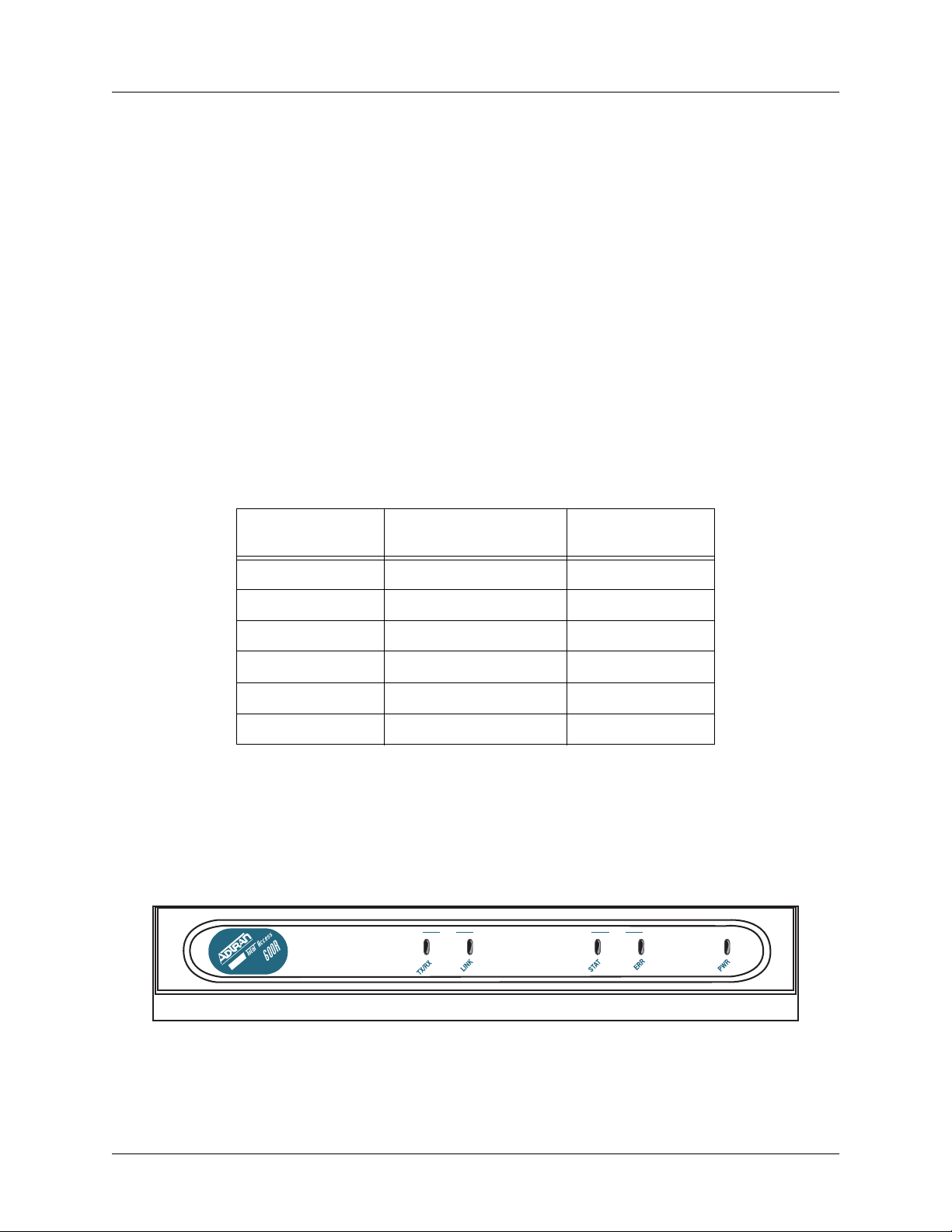
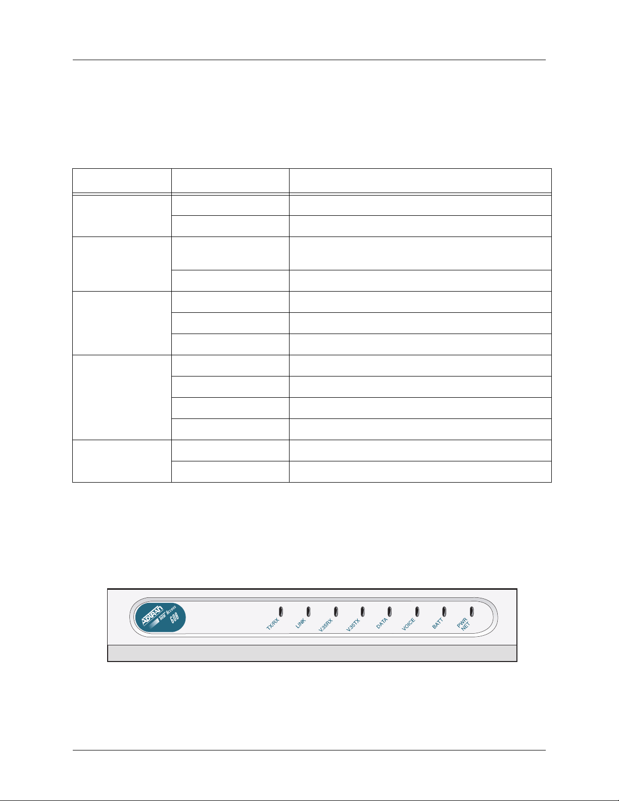
3. REVIEWING THE FRONT PANEL DESIGN
Total Access 600R
Figure 2 shows the Total Access 600R front panel.
LAN WAN
Maximum Current
Draw
Figure 1. Total Access 600R Front Panel Layout
61200624L1-1B © 2004 ADTRAN, Inc. 23
Page 24
Section 2 Engineering Guidelines Total Access 600 Series System Manual
Front Panel LEDs
The front panel provides five status LEDs to monitor operation and activity. Table 3 provides LED
descriptions for Total Access 600R systems.
Table 2. Total Access 600R Front Panel LEDs
For these LEDs... This color light... Indicates that...
LAN TX/RX
LAN LINK
WAN STAT
WAN ERR
PWR
Off there is no data traffic on the LAN.
Green (blinking) there is data traffic on the LAN.
Off the physical link is down; there is no Ethernet
connection.
Green (solid) there is link integrity on the LAN (physical link is up).
Red (solid) the T1 is in red alarm or T1 sync loss has occurred.
Yellow (solid) the T1 is in yellow alarm.
Green (solid) the unit is not in alarm.
Off the WAN link is up and error-free.
Red (solid) severe errors are present on the WAN link.
Red (flashing) the T1 is down.
Yellow (solid) errors are present on the WAN link.
Green (solid) power is supplied to the unit.
Off power is not supplied to the unit.
Total Access 604/608
The front panels of the Total Access 604/608 systems are identical. Figure 2 shows the Total Access 608
front panel as a representative of both models.
Figure 2. Total Access 604/608 Front Panel Layout
24 © 2004 ADTRAN, Inc. 61200624L1-1B
Page 25

Total Access 600 Series System Manual Section 2 Engineering Guidelines
Front Panel LEDs
The front panel provides eight status LEDs to monitor operation and activity. The LED functionality
varies based on product and software load (TDM versus ATM). Table 3 provides LED descriptions for
Total Access 604/608 systems employing TDM software, and Table 4 on page 26 lists ATM software LED
functionality.
Table 3. Total Access 604/608 TDM Front Panel LEDs
For these LEDs... This color light... Indicates that...
TX/RX
LINK
V.35 R X
V.35 T X
DATA
VOICE
Off there is no data traffic on the LAN.
Green (blinking) there is data traffic on the LAN.
Off the physical link is down; there is no Ethernet
connection.
Green (solid) there is link integrity on the LAN (physical link is up).
Off no data traffic is being received on the V.35.
Green (blinking) data is being received on the V.35.
Off no data traffic is being transmitted on the V.35.
Green (blinking) data is being transmitted on the V.35.
Red (solid) the T1 is in red alarm or T1 sync loss has occurred.
Yellow (solid) the T1 is in test.
Green (solid) Layer 2 is up.
Off the T1 is down.
Green (blinking) the phone is off hook.
Green (solid) the T1 is up and the phone is on hook.
BATT
PWR NET
61200624L1-1B © 2004 ADTRAN, Inc. 25
Off there is no power connected to the system.
Green (solid) AC power is operational and battery is functional.
Red/Green (alternating) AC power is operational, but the battery is not functional.
Amber (solid) AC power has failed and the battery is functional.
Red/Amber (alternating) AC power has failed and the battery is not functional.
Green (solid) Layer 1 is up.
Green (blinking) Layer 1 is down.
Page 26

Section 2 Engineering Guidelines Total Access 600 Series System Manual
Table 4. Total Access 6XX ATM Front Panel LEDs
For these LEDs... This color light... Indicates that...
TX/RX
LINK
V.35 R X
V.35 T X
DATA
VOICE
VOICE
(if Gateway is
Jetstream)
Off there is no data traffic on the LAN.
Green (blinking) there is data traffic on the LAN.
Off the physical link is down; no Ethernet connection.
Green (solid) there is link integrity on the LAN; the physical link is up.
Off no data traffic is being received on the V.35.
Green (blinking) data is being received on the V.35.
Off no data traffic is being transmitted on the V.35.
Green (blinking) data is being transmitted on the V.35.
Red (solid) Layer 2 is down.
Green (solid) Layer 2 is up.
Red (solid) the T1 is non-operational.
Green (blinking) the phone is off hook.
Red (solid) gateway link is down.
Green (solid) gateway link is up.
VOICE
(if Gateway is
Coppercom or
LES-CAS)
VOICE
(if Gateway is
Tollbridge)
VOICE
(if no Gateway)
BATT
PWR NET
Red (solid) Layer 2 is down.
Green (solid) Layer 2 is up.
Red (solid) gateway status is inactive.
Green (solid) gateway status is active.
Yellow (blinking) the phone is off hook.
Off the phone is on hook.
Off there is no power connected to the system.
Green (solid) AC power is operational and battery is functional.
Red/Green (alternating) AC power is operational, but the battery is not functional.
Amber (solid) AC power has failed and the battery is functional.
Red/Amber (alternating) AC power has failed and the battery is not functional.
Green (solid) Layer 1 is up.
Green (blinking slowly) unit was unable to train – Layer 1 is down.
Green (blinking rapidly) Layer 1 is training (SDSL and SHDSL only).
26 © 2004 ADTRAN, Inc. 61200624L1-1B
Page 27
Total Access 600 Series System Manual Section 2 Engineering Guidelines
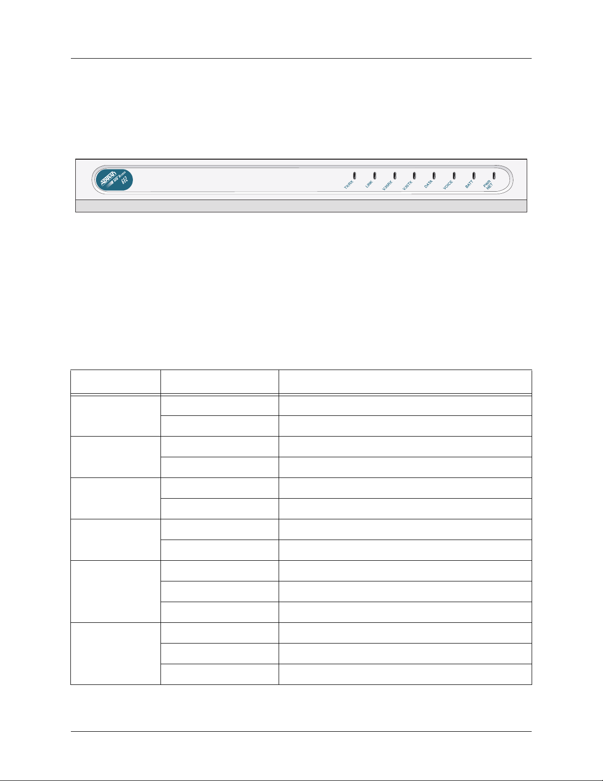
Total Access 612/616/624
The front panels of the Total Access 612/616/624 systems are identical. Figure 3 shows the Total Access
612 front panel as a representative of all models.
Figure 3. Total Access 612/616/624 Front Panel Layout
Front Panel LEDs
The front panel provides eight status LEDs to monitor operation and activity. The LED functionality
varies based on product and software load (TDM versus ATM). Table 5 provides LED descriptions for
Total Access 612/616/624 systems employing TDM software, and Table 4 on page 26 lists ATM software
LED functionality.
Table 5. Total Access 612/616/624 TDM Front Panel LEDs
For these LEDs... This color light... Indicates that...
TX/RX
LINK
V.3 5 RX
V.3 5 TX
DATA
VOICE
Off there is no data traffic on the LAN.
Green (blinking) there is data traffic on the LAN.
Off the physical link is down; no Ethernet connection.
Green (solid) there is link integrity on the LAN; the physical link is up.
Off no data traffic is being received on the V.35.
Green (blinking) data is being received on the V.35.
Off no data traffic is being transmitted on the V.35.
Green (blinking) data is being transmitted on the V.35.
Red (solid) the T1 is in red alarm or T1 sync loss has occurred.
Yellow (solid) the T1 is in test.
Green (solid) Layer 2 is up.
Red (solid) the T1 is down.
Green (blinking) the phone is off hook.
Green (solid) the T1 is operational and the phone is on hook.
61200624L1-1B © 2004 ADTRAN, Inc. 27
Page 28
Section 2 Engineering Guidelines Total Access 600 Series System Manual
Table 5. Total Access 612/616/624 TDM Front Panel LEDs (Continued)
For these LEDs... This color light... Indicates that...
BATT
PWR NET
Off there is no power connected to the system.
Green (solid) AC power is operational and battery is functional.
Red/Green (alternating) AC power is operational, but the battery is not functional.
Amber (solid) AC power has failed and the battery is functional.
Red/Amber (alternating) AC power has failed and the battery is not functional.
Green (solid) Layer 1 is up.
Green (blinking) Layer 1 is down.
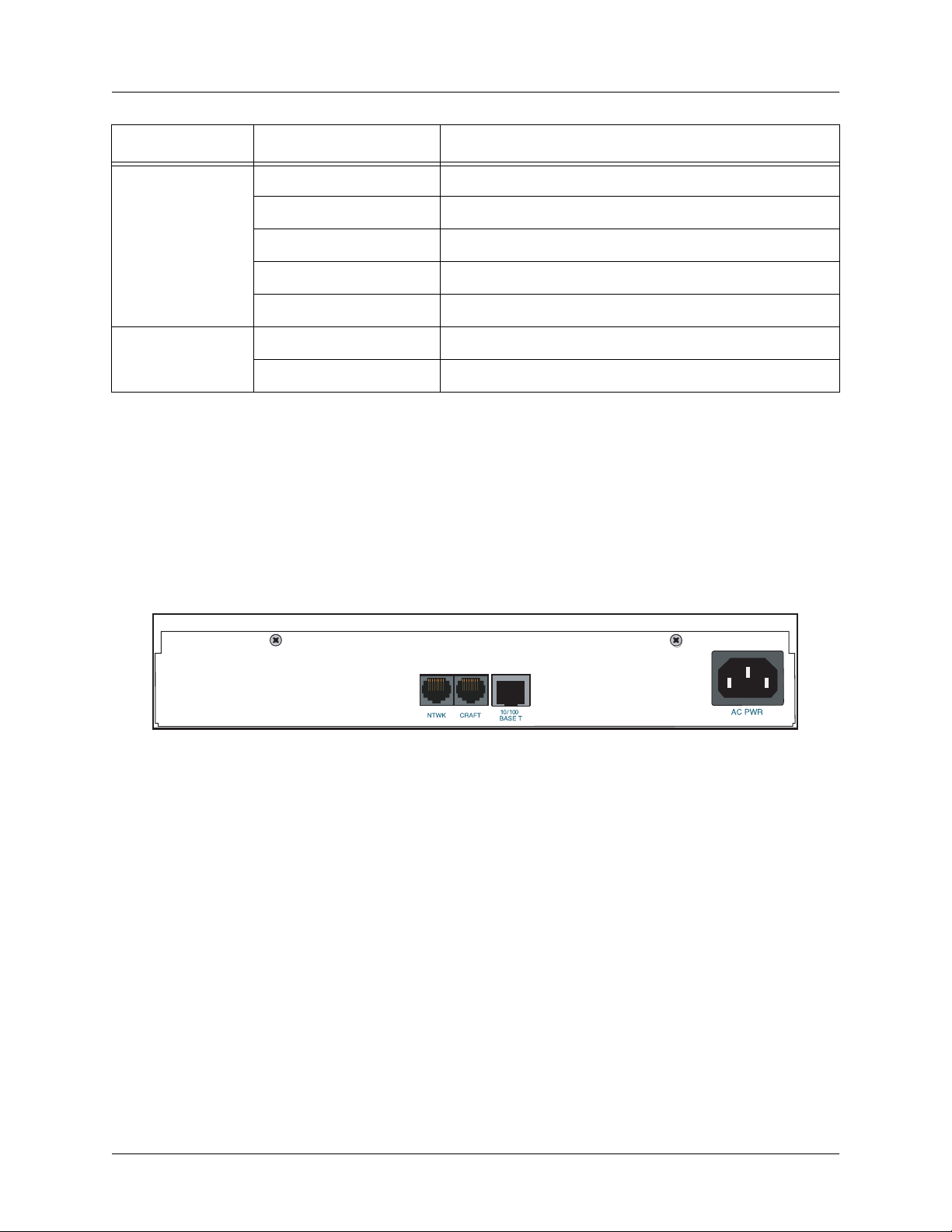
4. REVIEWING THE REAR PANEL DESIGN
The Total Access 600R provides a NTWK connection (via an RJ-48 connector), a CRAFT interface (via an
RJ-49 connector), a
3-prong detachable power cord). In addition, systems can include the optional
RJ-48 connector). The Total Access 600R rear panel differs from the rest of the family in that it does not
have a
VOICE connection (50-pin amphenol connector). Figure 4 illustrates a standard Total Access 600R
rear panel.
10/100BASET interface (via an RJ-48 connector), and an AC PWR connection (via a
DSX-1 interface (via an
Figure 4. Total Access 600R Rear Panel
All other Total Access 600 Series systems contain the following rear panel interfaces regardless of the
model:
connector), a
connector), a
modular plug), and an
can include either a
VOICE connection (via a 50-pin female amphenol connector), a NTWK connection (via an RJ-48
CRAFT interface (via an RJ-48 connector), a 10/100BASET interface (via an RJ-48
V.35 connection (via a 34-pin Winchester-style connector), a BATT connection (via a 3-pin
AC PWR connection (via a 3-prong detachable power cord). In addition, systems
LIFE LINE analog interface (via an RJ-48 connector) or an optional DSX-1 interface
(via an RJ-48 connector). Figure 5 on page 29 illustrates a standard Total Access 604/608, and Figure 6
and Figure 7 on page 29 illustrate the Total Access 604/608 rear panels with the
DSX-1 interfaces, respectively. Figures 8 through 10 on page 29 illustrate the Total Access 612/616/624
LIFE LINE analog and
rear panels.
28 © 2004 ADTRAN, Inc. 61200624L1-1B
Page 29
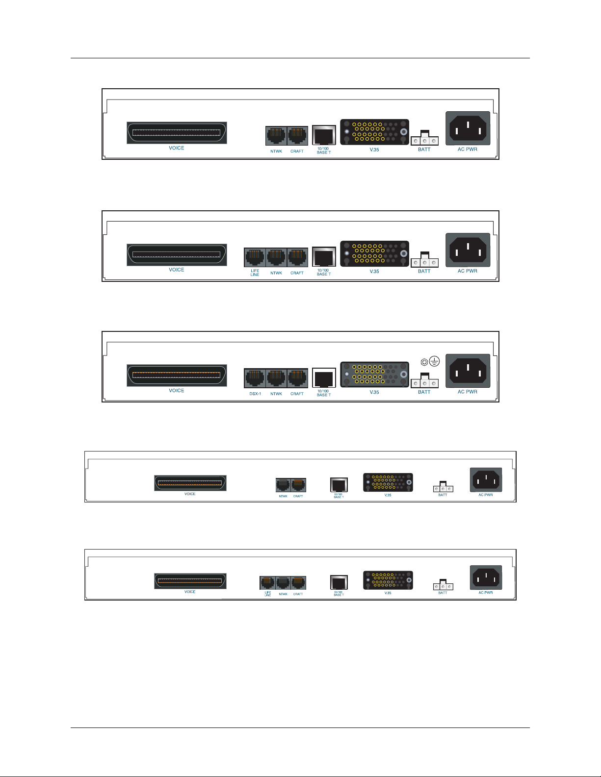
Total Access 600 Series System Manual Section 2 Engineering Guidelines
Figure 5. Total Access 604/608 Rear Panel
Figure 6. Total Access 604/608 Rear Panel with Optional Life Line POTS
Figure 7. Total Access 604/608 Rear Panel with Optional DSX-1 Interface
Figure 8. Total Access 612/616/624 Rear Panel
Figure 9. Total Access 612/616/624 Rear Panel with Optional Life Line POTS
61200624L1-1B © 2004 ADTRAN, Inc. 29
Page 30
Section 2 Engineering Guidelines Total Access 600 Series System Manual
1
2
3
1
2
3
1
2
3
1
2
3
4
Figure 10. Total Access 612/616/624 Rear Panel with Optional DSX-1 Interface
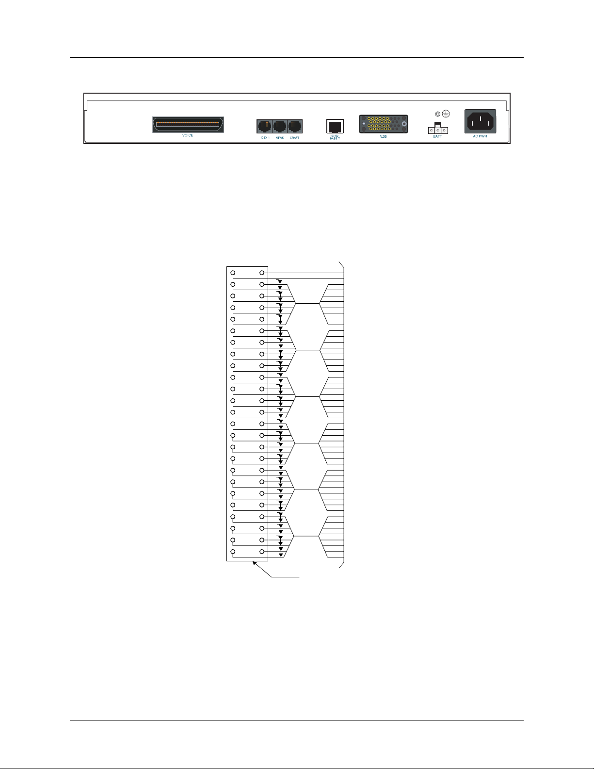
VOICE Connection
A single 50-pin female amphenol connector provides the interconnect wiring for the analog FXS and FXO
(available as an option only on the Total Access 624) circuits. Figure 11 shows the
pinout.
VOICE connector
Slot 5
NC
NC
T
Circuit
R
T
Circuit
R
T
Circuit
R
T
Circuit
R
T
Circuit 4
R
T
Circuit
R
T
Circuit
R
T
Circuit
R
T
Circuit 4
R
T
Circuit 3
R
T
Circuit 2
R
T
Circuit 1
R
T
Circuit 4
R
T
Circuit
R
T
Circuit
R
T
Circuit
R
T
Circuit 4
R
T
Circuit 3
R
T
Circuit 2
R
T
Circuit 1
R
T
Circuit 4
R
T
Circuit
R
T
Circuit
R
T
Circuit
R
5025
P
4924
P
4823
4722
4621
4520
4419
4318
4217
4116
4015
3914
3813
3712
3611
3510
349
338
327
316
305
294
283
272
261
Slot 6
P
P
P
P
P
P
P
P
Slot 4
P
P
P
P
Slot 3
P
P
P
P
Slot 2
P
P
P
P
Slot 1
P
P
50 PIN
AMP
RECEPTACLE
NTWK Connection
The Total Access 600 Series NTWK connection is provided via an RJ-48 connector regardless of the
Figure 11. VOICE Connector Pin Assignments
network technology (T1, ADSL, SDSL, etc.). Table 6 shows the
NTWK connection pinout (identical across
all technologies).
30 © 2004 ADTRAN, Inc. 61200624L1-1B
Page 31

Total Access 600 Series System Manual Section 2 Engineering Guidelines
Table 6. NTWK Connection Pinout
PIN NAME DESCRIPTION
1
2 RX TIP Receive data from the network
3, 6-8 —––––– Unused
4 TX RING Transmit data toward the network
5 TX TIP Transmit data toward the network
RX RING Receive data from the network
CRAFT Port
The CRAFT port (EIA-232) on the rear panel connects to a computer or modem and provides the following
functions:
• Accepts EIA-232 input from a PC or a modem for controlling the Total Access 600 Series.
• Baud rate is user-configurable.
• Acts as input for either VT100 or PC control.
• Acts as an interface for flash memory software downloads using XMODEM.
Table 7 shows the CRAFT port pinout.
Table 7. CRAFT Pinout
PIN NAME DESCRIPTION
1 GND Ground – connected to unit chassis
2 RTS Request to send – flow control
3 RXDATA Receive data
4 DTR Data terminal ready
5 TXDATA Transmit data
6 CD Carrier detect
7 —––––– Unused
8 CTS Clear to send - flow control
A DB-9 to RJ-48 adapter is needed to connect a PC or VT100 terminal to the
CRAFT port. This adapter is
not part of the Total Access 600 Series shipment. You may obtain a free adapter (P/N 3196ADPT001) by
contacting ADTRAN Technical Support or by adding the adapter to the system order. You can also build
your own adapter by purchasing unassembled adapter kits from Black Box or Datacomm Warehouse (or
other equivalent companies). The adapter pinout is shown in Table 8.
Table 8. DB-9 to RJ-48 Adapter Pinout
DB-9 RJ-48 DESCRIPTION
2 5 Transmit Data
3 3 Receive Data
5 1 Ground
61200624L1-1B © 2004 ADTRAN, Inc. 31
Page 32

Section 2 Engineering Guidelines Total Access 600 Series System Manual
Table 8. DB-9 to RJ-48 Adapter Pinout (Continued)
DB-9 RJ-48 DESCRIPTION
Note: All other pins are unused.
32 © 2004 ADTRAN, Inc. 61200624L1-1B
Page 33

Total Access 600 Series System Manual Section 2 Engineering Guidelines
10/100BaseT Connection
The 10/100BASET port (RJ-48C) provides a 10/100BaseT Ethernet LAN connection for IP Routing, TFTP,
SNMP, and Telnet connections. Table 9 shows the 10/100BaseT pinout.
Table 9. Ethernet Pinout
PIN NAME DESCRIPTION
1
2 TX2 Transmit Negative
3 RX1 Receive Positive
4, 5 —––––– Unused
6 RX2 Receive Negative
7, 8 —––––– Unused
TX1 Transmit Positive
V.35 Connection
The Total Access 600 Series system provides a single V.35 Winchester-style connection on the rear of the
unit (as defined in Table 10).
Table 10. V.35 Winchester Pinout
PIN/CCIT DESCRIPTION
A/101 Protective ground (PG)
B/102 Signal ground (SG)
C/105 Request to send (RTS) from DTE
D/106 Clear to send (CTS) to DTE
E/107 Data set ready (DSR) to DTE
E/109 Data carrier detect
H/— Data terminal ready (DTR) from DTE
J/— Ring indicator (RI)
R/104 Received data (RD-A) to DTE
T/104 Received data (RD-B) to DTE
PIN/CCIT DESCRIPTION
V/115 RX clock (RC-A) to DTE
X/115 RX clock (RC-B) to DTE
P/103 Transmitted data (TD-A) from DTE
S/103 Transmitted data (TD-B) to DTE
Y/114 TX clock (TC-A) to DTE
AA/114 TX clock (TC-B) to DTE
U/113 External TX clock (ETC-A) from DTE
W/113 External TX clock (ETC-B) from DTE
NN/— Test mode (TM) to DTE
Battery Backup Connection
An optional battery backup system is available for the Total Access 604/608 (P/N 1200641L1) and the Total
Access 612/616/624 (P/N 1175044L1, 1175044L2, or 1175044L4). For more details on the battery backup
system installation and operation, refer to the documentation available for your specific battery backup unit.
AC Power Connection
Each unit includes an auto ranging 90-250 VAC, 50/60 Hz power supply with a 3-prong removable cable.
Connect the power supply to a standard 120 VAC, 60 Hz electrical outlet for proper operation.
61200624L1-1B © 2004 ADTRAN, Inc. 33
Page 34

Section 2 Engineering Guidelines Total Access 600 Series System Manual
Life Line Analog Connection
The
LIFE LINE
analog connection is only available on Total Access 600 Series xDSL
models.
The LIFE LINE analog connection provides assured voice for port 1. If the unit loses power or goes into
alarm, the network voice service is inhibited and the on-board relay opens. The first port of the voice
connector is provided with analog voice from the
be plugged into the
LIFE LINE port. Table 11 provides the LIFE LINE port pinout.
Table 11. LIFE LINE Connection Pinout
PIN DESCRIPTION
1,2 Unused
3 Life Line Ring
4 Life Line Tip
5,6 Unused
LIFE LINE analog connection. A regular POTS line must
DSX-1 Interface
The
Total Access 600 Series systems without the DSX-1 interface are not field-upgradeable to
add DSX-1 access.
interface is optional and must be requested at the time of order placement.
DSX-1
Table 12 provides the DSX-1 port pinout.
Table 12. DSX-1 Connection Pinout
PIN NAME DESCRIPTION
1
2 TX TIP Transmit data toward the network (TIP)
3, 6-8 —––––– Unused
4 RX RING Receive data from the network (RING)
5 RX TIP Receive data from the network (TIP)
TX RING Transmit data toward the network (RING)
34 © 2004 ADTRAN, Inc. 61200624L1-1B
Page 35

Total Access 600 Series System Manual Section 2 Engineering Guidelines
5. AT-A-GLANCE SPECIFICATIONS
Table 13 lists the unit specifications.
Table 13. Specifications
Application Feature Specification
T1 Network Interface
Physical Interface RJ-48C
Line Rate 1.544 Mbps +/- 75 bps
Framing D4 (SF)/ESF
AT&T 54016
ANSI T1.403
Line Code AMI/B8ZS
ADSL Network Interface (ITU G.992.1)
Throughput Up to 8 Mbps downstream
Up to 1 Mbps upstream
Interoperability Interoperate with G.992.1 compliant DSLAMs
G.SHDSL Network Interface (ITU G.991.2)
Line Rate 192 kbps to 2.3 Mbps
SDSL Network Interface (2B1Q Conexant-based)
Line Rate 160 kbps to 2.3 Mbps
Training Conexant Autobaud capable
ATM Support
Voice Codes PCM (G.711)
PVC Capability 6 PVCs (1 voice, 5 data)
Echo Cancellation G.165/G.168 Echo Cancellation, 8 ms echo tail
QoS Support VBR-rt (voice)
Specifications AAL2 (voice)
Frame Relay Support
32K ADPCM (G.726)
UBR (data)
AAL5 (data, voice)
RFC 1483 (multiprotocol over ATM)
RFC 2364 (PPPoA)
Specifications FRF.5
FRF.8
61200624L1-1B © 2004 ADTRAN, Inc. 35
Page 36

Section 2 Engineering Guidelines Total Access 600 Series System Manual
Table 13. Specifications (Continued)
Application Feature Specification
Analog Ports
Number of FXS Ports 4 ports for Total Access 604
8 ports for Total Access 608
12 ports for Total Access 612
16 ports for Total Access 616
24 ports for Total Access 624
Modes FXS Loop Start
FXS Ground Start
TR08 Single
TR08 UVG
DP0
Tandem (E&M)
Ringing Balanced ringing, 5 REN per port not to exceed
35 REN
Ring Voltage Fixed 70 VACrms with 20 VDC offset
Routing (Ethernet)
Management
Specifications IEEE 802.3
IP Support TCP, RIP V1, RIP V2, UDP, ICMP, ARP, UDP
Relay, SYSLOG
PPP Support LCP, IPCP, BCP
DHCP DHCP Server to LAN
DHCP from network
CRAFT Interface EIA 232, Physical RJ-48C
Ethernet 10/100BaseT
Interface
SNMP V1 support
• 604/608 ATM units running D.01.36
firmware or previous
• 612/616/624 ATM units running D.01.30
firmware or previous
SNMP V2 support
• TDM units running A.04 firmware or later
Full menu-driven Telnet access
Software download via TFTP
Support for VoDSL gateway management
systems and firmware download
36 © 2004 ADTRAN, Inc. 61200624L1-1B
Page 37

NETWORK TURNUP PROCEDURE
This section provides shipment contents list, grounding instructions, mounting options, and specifics of
supplying power to the unit.
CONTENTS
Tools Required . . . . . . . . . . . . . . . . . . . . . . . . . . . . . . . . . . . . . . . . . . . . . . . . . . . . . . . . . . . . . . . . . 36
Unpack and Inspect the SYSTEM . . . . . . . . . . . . . . . . . . . . . . . . . . . . . . . . . . . . . . . . . . . . . . . . . .36
Contents of ADTRAN Shipments . . . . . . . . . . . . . . . . . . . . . . . . . . . . . . . . . . . . . . . . . . . . . . . . . 37
Grounding Instructions . . . . . . . . . . . . . . . . . . . . . . . . . . . . . . . . . . . . . . . . . . . . . . . . . . . . . . . . . . 37
Mounting Options . . . . . . . . . . . . . . . . . . . . . . . . . . . . . . . . . . . . . . . . . . . . . . . . . . . . . . . . . . . . . . . 38
Wallmounting the Unit . . . . . . . . . . . . . . . . . . . . . . . . . . . . . . . . . . . . . . . . . . . . . . . . . . . . . . . . . 38
Rackmounting the Total Access 612/616/624 . . . . . . . . . . . . . . . . . . . . . . . . . . . . . . . . . . . . . . . 40
Supplying Power to the Unit . . . . . . . . . . . . . . . . . . . . . . . . . . . . . . . . . . . . . . . . . . . . . . . . . . . . . . 40
AC Powered Systems . . . . . . . . . . . . . . . . . . . . . . . . . . . . . . . . . . . . . . . . . . . . . . . . . . . . . . . . . 40
FIGURES
Figure 1. Wallmount Orientation . . . . . . . . . . . . . . . . . . . . . . . . . . . . . . . . . . . . . . . . . . . . . . . . . . 39
Figure 2. Wallmounting the Unit . . . . . . . . . . . . . . . . . . . . . . . . . . . . . . . . . . . . . . . . . . . . . . . . . . 39
61200624L1-1B © 2004 ADTRAN, Inc. 35
Page 38

Network Turnup Procedure Total Access 600 Series System Manual
1. INTRODUCTION
This section discusses Total Access 600 Series installation.
2. TOOLS REQUIRED
The tools required for wallmount installation of the unit are:
• Four #8 x 3/4 inch pan-head wood screws
• Drill and drill bit set
• Flat head screwdriver (medium)
• Two Phillips head screwdrivers (small/medium)
• Wire-wrap gun (optional)
• 25-pair male amphenol cable (customer connection)
• Selected punch-down block and tool
To prevent electrical shock, do not install equipment in a wet location or during a
lightning storm.
During installation, power should be the last connection made.
Electronic equipment can be damaged by static electrical discharge. Before handling
modules, put on an antistatic discharge wrist strap to prevent damage to electronic
components. Place equipment in antistatic packing material when transporting or storing.
When working on equipment, always place it on an approved antistatic mat that is
electrically grounded.
3. UNPACK AND INSPECT THE SYSTEM
Each unit is shipped in its own cardboard shipping carton. Open each carton carefully and avoid deep
penetration into the carton with sharp objects.
After unpacking the unit, inspect it for possible shipping damage. If the equipment has been damaged in
transit, immediately file a claim with the carrier, and then contact ADTRAN Customer Service (see
Customer Service, Product Support Information, and Training in the front of this manual).
36 © 2004 ADTRAN, Inc. 61200624L1-1B
Page 39

Total Access 600 Series System Manual Section 3 Network Turnup Procedure
Contents of ADTRAN Shipments
Your ADTRAN shipment includes the following items:
• The Total Access 6XX unit with attached wallmount brackets
• The Total Access 600 Series System CD – ADTRAN P/N 3253052
• Hardware revision notice card – ADTRAN P/N 61200624L1-17
• Mounting instructions – ADTRAN P/N 61200624L1-19
• RJ-45 to RJ-45 8-pin cable (6 ft) –ADTRAN P/N 3127004
• Cable tie (for securing attached cables) – ADTRAN P/N 3292032
• Four rubber feet (for table top installations) – ADTRAN P/N 3270BF003
• 3-prong, detachable power cord – ADTRAN P/N 3127009
Customer must supply Ethernet cable and the RJ-48 to DB-9 adapter and DB-9 serial
cable for configuration via the VT100
CRAFT interface.
4. GROUNDING INSTRUCTIONS
To following paragraphs provide grounding instruction information from the Underwriters’ Laboratory
UL60950 Standard for Safety of Information Technology Equipment Including Electrical Business
Equipment, with revisions dated March 15, 2002.
An equipment grounding conductor that is not smaller in size than the ungrounded branch-circuit supply
conductors is to be installed as part of the circuit that supplies the product or system. Bare, covered, or
insulated grounding conductors are acceptable. Individually covered or insulated equipment grounding
conductors shall have a continuous outer finish that is either green, or green with one or more yellow
stripes. The equipment grounding conductor is to be connected to ground at the service equipment.
The attachment-plug receptacles in the vicinity of the product or system are all to be of a grounding type,
and the equipment grounding conductors serving these receptacles are to be connected to earth ground at
the service equipment.
A supplementary equipment grounding conductor shall be installed between the product or system and
ground that is in addition to the equipment grounding conductor in the power supply cord.
The supplementary equipment grounding conductor shall not be smaller in size than the ungrounded
branch-circuit supply conductors. The supplementary equipment grounding conductor shall be connected
to the product at the terminal provided, and shall be connected to ground in a manner that will retain the
ground connection when the product is unplugged from the receptacle. The connection to ground of the
supplementary equipment grounding conductor shall be in compliance with the rules for terminating
bonding jumpers at Part K or Article 250 of the National Electrical Code, ANSI/NFPA 70. Termination of
the supplementary equipment grounding conductor is permitted to be made to building steel, to a metal
electrical raceway system, or to any grounded item that is permanently and reliably connected to the
electrical service equipment ground.
The supplemental grounding conductor shall be connected to the equipment using a number 8 ring terminal
and should be fastened to the grounding lug provided on the rear panel of the equipment. The ring terminal
should be installed using the appropriate crimping tool (AMP P/N 59250 T-EAD Crimping Tool or
equivalent).
61200624L1-1B © 2004 ADTRAN, Inc. 37
Page 40

Network Turnup Procedure Total Access 600 Series System Manual
5. MOUNTING OPTIONS
All units may be wallmounted or installed in a table-top application. In addition, the Total Access 612/616/624
units are available for 19- or 23-inch rackmount installations. Wallmount brackets are included with the unit
and are already attached. For a rackmount installation, optional rackmount brackets must be purchased (19” –
P/N 1200627L1, 23” – P/N 1200627L2).
Be careful not to upset the stability of the equipment mounting rack when installing this
product.
Wallmounting the Unit
Tools Needed
The unit mounts and connects with standard fasteners and hand tools:
• Four #8 x 3/4-inch pan-head wood screws
• Drill and drill bit set
• Flat head screwdriver (medium)
• Two Phillips head screwdrivers (small/medium)
• Wire-wrap gun (optional)
• 25-pair male amphenol cable (customer connection)
• Selected punch-down block and tool
Follow these steps to wallmount the unit:
Wallmount Installation
Step Action
1. Decide on a location for the unit. Keep in mind that the unit needs to be mounted at or below
eye-level so that the LEDs are viewable.
IMPORTANT! Mount the chassis with LEDs facing to the side or down as shown in Figure 1 on
page 39 (not facing up).
Refer to Figure 2 on page 39 for a wallmount illustration.
2. Prepare the mounting surface by attaching a board (typically plywood, 3/4” to 1” thick) to a wall
stud.
IMPORTANT! Mounting to a stud ensures stability. Using sheetrock anchors may not provide
sufficient long-term stability.
3. Have someone else hold the unit in position as you install two #6 to #10 (1 1/2” or greater in
length) wood screws through the unit’s brackets and into the mounted board.
4. Proceed to the steps given in Supplying Power to the Unit on page 40.
38 © 2004 ADTRAN, Inc. 61200624L1-1B
Page 41

Total Access 600 Series System Manual Section 3 Network Turnup Procedure
Figure 1. Wallmount Orientation
Note: The Total Access 600 Series units come
equipped with wall mount brackets preinstalled.
Figure 2. Wallmounting the Unit
61200624L1-1B © 2004 ADTRAN, Inc. 39
Page 42

Network Turnup Procedure Total Access 600 Series System Manual
Rackmounting the Total Access 612/616/624
Tools Needed
The Total Access 612/616/624 mount and connect with standard fasteners and hand tools:
• Rackmount brackets (19”–P/N 1200627L1 or 23”–P/N 1200627L2)
• Flat head screwdriver (medium)
• Two Phillips head screwdrivers (small/medium)
• Wire-wrap gun (optional)
• 25-pair male amphenol cable (customer connection)
• Selected punch-down block and tool
Follow these steps to rackmount the Total Access 612/616/624:
Rackmount Installation
Step Action
1.
2.
3.
4.
Remove the wallmount brackets. (The Total Access 612/616/624 ships with wallmount
brackets attached.) Attach the mounting brackets to the side of the unit.
To avoid damaging the unit, use only the screws included in the mounting bracket
shipment when attaching mounting ears to the chassis.
Position the Total Access 612/616/624 in a stationary equipment rack. This unit takes
up 1 RU of space. To allow proper grounding, scrape the paint from the rack around
the mounting holes where the Total Access 612/616/624 will be positioned.
Have someone else hold the unit in position as you install two mounting bolts through
the unit’s brackets and into the equipment rack using a #2 Phillip’s screwdriver.
Proceed to the steps given in
Supplying Power to the Unit
.
6. SUPPLYING POWER TO THE UNIT
The Total Access 600 Series is not offered in DC powered versions. However, optional DC battery backup
systems are available for the Total Access 604/608 (P/N 1200641L1) and Total Access 612/616/624
(P/N 1175044L1, 2, or 4) systems.
AC Powered Systems
The AC powered unit comes equipped with a 3-prong, detachable power cord for connecting to a properly
grounded power receptacle. As shipped, the unit is set to factory default conditions. After installing the
unit it is ready for power-up. To apply power to the unit, ensure that it is properly connected to an
appropriate power source.
• This unit shall be installed in accordance with Article 400 and 364.8 of the NEC NFPA
70 when installed outside of a Restricted Access Location (i.e., central office, behind a
locked door, service personnel only area).
• Power to the Total Access 600 Series AC system must be from a grounded 90-130 VAC,
50/60 Hz source.
• Verify the power receptacle uses double-pole, neutral fusing.
• Maximum recommended ambient operating temperature is 45 ºC.
40 © 2004 ADTRAN, Inc. 61200624L1-1B
Page 43

USER INTERFACE GUIDE
This section of ADTRAN’s Total Access 600 Series System Manual is designed for use by network
administrators and others who will configure and provision the system. It contains information about
navigating the VT100 user interface, configuration information, and menu descriptions.
CONTENTS
Navigating the Terminal Menu . . . . . . . . . . . . . . . . . . . . . . . . . . . . . . . . . . . . . . . . . . . . . . . . . . . . 43
Terminal Menu Window . . . . . . . . . . . . . . . . . . . . . . . . . . . . . . . . . . . . . . . . . . . . . . . . . . . . . . . 43
Navigating using the Keyboard Keys . . . . . . . . . . . . . . . . . . . . . . . . . . . . . . . . . . . . . . . . . . . . . 45
MAIN Menu and System Control . . . . . . . . . . . . . . . . . . . . . . . . . . . . . . . . . . . . . . . . . . . . . . . . . . . 47
Selecting the Appropriate Menu . . . . . . . . . . . . . . . . . . . . . . . . . . . . . . . . . . . . . . . . . . . . . . . . . 47
Security Levels . . . . . . . . . . . . . . . . . . . . . . . . . . . . . . . . . . . . . . . . . . . . . . . . . . . . . . . . . . . . . . 48
Menu Descriptions . . . . . . . . . . . . . . . . . . . . . . . . . . . . . . . . . . . . . . . . . . . . . . . . . . . . . . . . . . . . . . 48
System Info . . . . . . . . . . . . . . . . . . . . . . . . . . . . . . . . . . . . . . . . . . . . . . . . . . . . . . . . . . . . . . . . . 49
System Config. . . . . . . . . . . . . . . . . . . . . . . . . . . . . . . . . . . . . . . . . . . . . . . . . . . . . . . . . . . . . . . 51
System Utility . . . . . . . . . . . . . . . . . . . . . . . . . . . . . . . . . . . . . . . . . . . . . . . . . . . . . . . . . . . . . . . 64
Interfaces . . . . . . . . . . . . . . . . . . . . . . . . . . . . . . . . . . . . . . . . . . . . . . . . . . . . . . . . . . . . . . . . . . 71
Interfaces (Network T1). . . . . . . . . . . . . . . . . . . . . . . . . . . . . . . . . . . . . . . . . . . . . . . . . . . . . . . . 71
Interfaces (Network SHDSL). . . . . . . . . . . . . . . . . . . . . . . . . . . . . . . . . . . . . . . . . . . . . . . . . . . . 75
Interfaces (Network SDSL) . . . . . . . . . . . . . . . . . . . . . . . . . . . . . . . . . . . . . . . . . . . . . . . . . . . . . 76
Interfaces (Network ADSL) . . . . . . . . . . . . . . . . . . . . . . . . . . . . . . . . . . . . . . . . . . . . . . . . . . . . . 77
Interfaces (DSX) . . . . . . . . . . . . . . . . . . . . . . . . . . . . . . . . . . . . . . . . . . . . . . . . . . . . . . . . . . . . . 78
Interfaces (ETH) . . . . . . . . . . . . . . . . . . . . . . . . . . . . . . . . . . . . . . . . . . . . . . . . . . . . . . . . . . . . . 81
Interfaces (V35). . . . . . . . . . . . . . . . . . . . . . . . . . . . . . . . . . . . . . . . . . . . . . . . . . . . . . . . . . . . . . 82
Interfaces (FXS) . . . . . . . . . . . . . . . . . . . . . . . . . . . . . . . . . . . . . . . . . . . . . . . . . . . . . . . . . . . . . 82
Interfaces (FXO) . . . . . . . . . . . . . . . . . . . . . . . . . . . . . . . . . . . . . . . . . . . . . . . . . . . . . . . . . . . . . 86
L2 Protocol (TDM Firmware). . . . . . . . . . . . . . . . . . . . . . . . . . . . . . . . . . . . . . . . . . . . . . . . . . . . 89
L2 Protocol (TDM Firmware) – T1 Interface . . . . . . . . . . . . . . . . . . . . . . . . . . . . . . . . . . . . . . . . 90
L2 Protocol (TDM Firmware) – T1 Interface > PPP . . . . . . . . . . . . . . . . . . . . . . . . . . . . . . . . . . 91
L2 Protocol (TDM Firmware) – T1 Interface > FRE Protocol . . . . . . . . . . . . . . . . . . . . . . . . . . . 93
L2 Protocol (TDM Firmware) – T1 Interface > HDLC Protocol . . . . . . . . . . . . . . . . . . . . . . . . . . 98
L2 Protocol (TDM Firmware) – T1 Interface > Auto Protocol . . . . . . . . . . . . . . . . . . . . . . . . . . . 99
L2 Protocol (ATM Firmware) . . . . . . . . . . . . . . . . . . . . . . . . . . . . . . . . . . . . . . . . . . . . . . . . . . . 100
L2 Protocol (ATM Firmware) – Network (NET) Interface . . . . . . . . . . . . . . . . . . . . . . . . . . . . . 101
L2 Protocol (ATM Firmware) – NET> ATM . . . . . . . . . . . . . . . . . . . . . . . . . . . . . . . . . . . . . . . . 101
L2 Protocol (ATM Firmware) – Network Interface > CuMtn FRE . . . . . . . . . . . . . . . . . . . . . . . 111
L2 Protocol (ATM Firmware) – V.35 Interface. . . . . . . . . . . . . . . . . . . . . . . . . . . . . . . . . . . . . . 113
L2 Protocol (ATM Firmware) – DSX Interface. . . . . . . . . . . . . . . . . . . . . . . . . . . . . . . . . . . . . . 115
L2 Protocol (All Firmware) – ETH Interface > 802.3 Protocol . . . . . . . . . . . . . . . . . . . . . . . . . . 116
Bridge . . . . . . . . . . . . . . . . . . . . . . . . . . . . . . . . . . . . . . . . . . . . . . . . . . . . . . . . . . . . . . . . . . . . 117
Router . . . . . . . . . . . . . . . . . . . . . . . . . . . . . . . . . . . . . . . . . . . . . . . . . . . . . . . . . . . . . . . . . . . . 119
Security . . . . . . . . . . . . . . . . . . . . . . . . . . . . . . . . . . . . . . . . . . . . . . . . . . . . . . . . . . . . . . . . . . . 141
DS0 Maps . . . . . . . . . . . . . . . . . . . . . . . . . . . . . . . . . . . . . . . . . . . . . . . . . . . . . . . . . . . . . . . . . 149
Appendices (T1 TDM Applications) . . . . . . . . . . . . . . . . . . . . . . . . . . . . . . . . . . . . . . . . . . . . . . . 152
Appendices (T1 ATM Applications) . . . . . . . . . . . . . . . . . . . . . . . . . . . . . . . . . . . . . . . . . . . . . . . 169
61200624L1-1B © 2004 ADTRAN, Inc. 41
Page 44

Section 4 User Interface Guide Total Access 600 Series System Manual
FIGURES
Figure 1. Top-Level Terminal Menu Window . . . . . . . . . . . . . . . . . . . . . . . . . . . . . . . . . . . . . . . . 43
Figure 2. Alternate Menu View . . . . . . . . . . . . . . . . . . . . . . . . . . . . . . . . . . . . . . . . . . . . . . . . . . . 44
Figure 3. System Info Menu . . . . . . . . . . . . . . . . . . . . . . . . . . . . . . . . . . . . . . . . . . . . . . . . . . . . . 49
Figure 4. System Config Menu . . . . . . . . . . . . . . . . . . . . . . . . . . . . . . . . . . . . . . . . . . . . . . . . . . . 51
Figure 5. System Utility Menu . . . . . . . . . . . . . . . . . . . . . . . . . . . . . . . . . . . . . . . . . . . . . . . . . . . . 64
Figure 6. Interfaces Menus . . . . . . . . . . . . . . . . . . . . . . . . . . . . . . . . . . . . . . . . . . . . . . . . . . . . . . 71
Figure 7. L2 Protocol (T1 TDM) Menu. . . . . . . . . . . . . . . . . . . . . . . . . . . . . . . . . . . . . . . . . . . . . . 89
Figure 8. L2 Protocol (SDSL ATM) Menu . . . . . . . . . . . . . . . . . . . . . . . . . . . . . . . . . . . . . . . . . . 100
Figure 9. Bridge Menu. . . . . . . . . . . . . . . . . . . . . . . . . . . . . . . . . . . . . . . . . . . . . . . . . . . . . . . . . 117
Figure 10. Router Menu . . . . . . . . . . . . . . . . . . . . . . . . . . . . . . . . . . . . . . . . . . . . . . . . . . . . . . . . 119
Figure 11. Security Menu . . . . . . . . . . . . . . . . . . . . . . . . . . . . . . . . . . . . . . . . . . . . . . . . . . . . . . . 141
Figure 12. DS0 Maps Menu . . . . . . . . . . . . . . . . . . . . . . . . . . . . . . . . . . . . . . . . . . . . . . . . . . . . . 149
Figure 7. Application Diagram . . . . . . . . . . . . . . . . . . . . . . . . . . . . . . . . . . . . . . . . . . . . . . . . . . . 169
Figure 10. Application Diagram . . . . . . . . . . . . . . . . . . . . . . . . . . . . . . . . . . . . . . . . . . . . . . . . . . . 174
TABLES
Table 1. Password Security Level . . . . . . . . . . . . . . . . . . . . . . . . . . . . . . . . . . . . . . . . . . . . . . . . .48
Table 2. Instructions for Changing Passwords . . . . . . . . . . . . . . . . . . . . . . . . . . . . . . . . . . . . . . . 52
Table 3. Telnet Security Levels . . . . . . . . . . . . . . . . . . . . . . . . . . . . . . . . . . . . . . . . . . . . . . . . . . . 54
42 © 2004 ADTRAN, Inc. 61200624L1-1B
Page 45

Total Access 600 Series System Manual Section 4 User Interface Guide
1. NAVIGATING THE TERMINAL MENU
To access the terminal menus and management features of the Total Access 6XX, connect the unit to a VT100
terminal (or VT100 terminal emulator) via the
CRAFT interface on the rear panel. Configure the terminal
settings for 9600 data rate, no parity, 8 data bits, 1 stop bit, and no flow control.
After connecting to the unit and beginning a terminal session, a login screen appears. There is no default
password for the Total Access 6XX; press
<E
> to access the terminal menus. (Refer to DLP-2, Logging in
NTER
to the System for detailed instructions.)
Terminal Menu Window
After logging in, all menu items and data fields are displayed in the terminal menu window (see Figure 1),
through which you have complete control of the unit.
Menu Path
Right Pane
Left Pane
Ethernet
Link Status
Slot Status
Mode
L2 Status (ATM)
DS0 Map (TDM)
Tool Tip
Extended Help
Telnet Info
(not present)
Figure 1. Top-Level Terminal Menu Window
Navigation Help
Network
Status
Config
Status
Menu Path
The first line of the terminal menu window (the menu path) shows the session’s current position (path) in the
menu structure. For example, Figure 1 shows the top-level menu with the cursor on the
submenu; therefore, the menu path reads TA6XX IAD/S
YSTEM CONFIG
.
S
YSTEM CONFIG
Window Panes
When you first start a terminal menu session, the terminal menu window is divided into left and right panes.
The left pane shows the list of available submenus, while the right pane shows the contents of the currently
selected submenu.
You can view the terminal windows in two ways: with fields and submenus displaying horizontally across the
right pane, or with fields and submenus displaying vertically down the right pane. Viewing submenus vertically
rather than horizontally allows you to see information at a glance rather than scrolling horizontally across the
window. To change the view, move your cursor to an index number and press
<E
>. Figure 2 on page 44
NTER
shows this alternate view. Fields and submenu names may vary slightly in this view.
61200624L1-1B © 2004 ADTRAN, Inc. 43
Page 46

Section 4 User Interface Guide Total Access 600 Series System Manual
Figure 2. Alternate Menu View
Window Pane Navigation
Use the following chart to assist you in moving between and within the two window panes.
To do this... Press this key...
Move from left pane to right pane Tab
Enter
Right arrow
Move from right pane to left pane Tab
Escape
Left arrow
Backspace
Move within each pane Up arrow
Down arrow
Left arrow
Right arrow
Right Window Pane Notation
The right window pane shows the contents of the currently selected menu. These contents include both
submenu items and data fields. Some submenus contain additional submenus and some data fields
contain additional data fields. The following chart explains the notation used to identify these
additional items.
This notation... Means that...
[+] more items are available when selected.
[DATA] more items are available when selected.
<+> an action is to be taken, such as activating a test.
Highlighted menu item you can enter data in this field.
Underlined field the field contains read-only information.
44 © 2004 ADTRAN, Inc. 61200624L1-1B
Page 47

Total Access 600 Series System Manual Section 4 User Interface Guide
Additional Terminal Menu Window Features
• Mode – displays the network interface mode of the unit (for example, T1 IAD, SHDSL IAD, SDSL
IAD, ADSL IAD)
• L2 Status – displays the current status of the L2 protocol (ATM sync is either up or down) – ATM Only
• DS0 Mapping – displays the current mapping of DS0s in the system. DS0s mapped to the router
display r, unmapped DS0s display –, and all other DS0s display *.
• Tool Tip – provides a brief description of the currently selected mode.
• Slot Status – displays type of module installed in each slot. No entry will appear for slots not containing
a module.
• Telnet Info – displays the user name when connected via Telnet. This information is not displayed when
connecting to the system via the
CRAFT interface.
• Ethernet Link Status – displays the current status of the integrated Ethernet interface (located on the rear
of the chassis).
• Extended Help – displays information about selected commands <
CTRL+A
>.
• Navigation Help – lists characters used for navigating the terminal menu and session management
<
CTRL+Z
>.
• Config Status – displays * when current configuration contains changes that have not been saved to
flash memory. Save changes by backing out to the main menu, or press <CTRL + W> to force a manual
save.
Navigating using the Keyboard Keys
You can use various keystrokes to move through the terminal menu, to manage a terminal menu session,
and to configure the system. Press <CTRL+Z > to activate a pop-up screen listing the navigation
keystrokes.
Moving through the Menus
To do this... Press this key...
Return to the home screen H
Jump between two menu items
Press <J> while the cursor is located on a menu item, and you jump back to the
main screen.
Go to another menu item, press <J>, and you jump back to the screen that was
displayed the first time you pressed <J>.
Press <J> anytime you want to jump between these items.
Select items Arrows
Edit a selected menu item Enter
Cancel an edit Escape
Close pop-up help screen Escape
J
Move between the left and right panes Tab
Arrows
Move to the top of a screen A
61200624L1-1B © 2004 ADTRAN, Inc. 45
Page 48

Section 4 User Interface Guide Total Access 600 Series System Manual
To do this... Press this key...
Move to the bottom of a screen Z
Ascend one menu level Backspace
Jump to terminal mode CTRL+T
Jump to NAT menu CTRL+N
Session Management Keystrokes
To do this... Press this key...
Log out of a session CTRL+L
Refresh the screen
CTRL+R
To save time, only the portion of the screen that has changed is refreshed. This
option should only be necessary if the display picks up incorrect characters caused
by disconnecting and reconnecting the terminal session.
Configuration Keystrokes
To do this... Press this key...
Restore factory default settings
This setting restores the factory defaults based on the location of the cursor. If the
cursor is on an interface line (in the I
NTERFACES
menu), then only the selected
interface is updated to factory defaults.
Copy selected items to the clipboard
The amount of information you can copy depends on the cursor location when you
press <C>:
If the cursor is over an editable field, only that item is copied.
If the cursor is over the index number of a list, then all of the items in the row of
the list are copied. For example, if the cursor is over the selection # field in the
I
NTERFACES
screen, all of the information associated with the interface is
copied.
Paste the item stored in the clipboard, if the information is compatible
You must confirm all pastes — except those to a single editable field.
F
C
P
Increment the value of certain types of fields by one when you paste information
>
into those fields
Decrement the value of certain types of fields by one when you paste information
<
into those fields
Save the current configuration immediately to flash memory CTRL+W
Insert a new list item
For example, add a new item to the T
ELNET USER
connection list by pressing <I>
I
while the cursor is over the index number.
46 © 2004 ADTRAN, Inc. 61200624L1-1B
Page 49

Total Access 600 Series System Manual Section 4 User Interface Guide
To do this... Press this key...
Delete a list item
For example, delete an item from the T
ELNET USER
connection list by pressing
D
<D> while the index number is active.
Getting Help
The bottom line of the terminal menu window contains context-sensitive help information. When the
cursor is positioned over a set of configuration items, a help message displays (when available) providing a
description of the item. When more detailed help is available for a particular item, ^A displays at the
bottom of the window. At this point, pressing <CTRL+A> displays a pop-up help screen with information
about the item.
Press <CTRL+Z> to activate a help screen that displays the available keystrokes you can use to navigate
the main menu system. Press <Exit> to remove these help screens.
2. MAIN MENU AND SYSTEM CONTROL
Selecting the Appropriate Menu
The main menu system is the access point to all other operations. Each menu item has several functions
and submenus that identify and provide access to specific operations and parameters. Use the following
chart to help select the appropriate menu.
To do this... Go to this menu...
Review and monitor general system information for the Total Access 6XX
Set up the operational configuration for the Total Access 6XX
Upgrade firmware, perform config transfers, ping, and access terminal mode
Review and configure settings for all interfaces (including installed modules)
Configures the Layer 2 protocol for the various interfaces (T1, Ethernet, etc.)
S
YSTEM INFO
S
YSTEM CONFIG
S
YSTEM UTILITY
I
NTERFACES
L2 P
ROTOCOL
and provides all applicable L2 status information
Configure the bridging parameters and view applicable bridging statistics
Define, configure, and monitor all Total Access 6XX Router functions
Configure security filters for L2 traffic and define RADIUS server parameters
Map data and voice ports (from integrated interfaces as well as installed
B
RIDGE
R
OUTER
S
ECURITY
DS0 M
APS
modules) to network time slots
61200624L1-1B © 2004 ADTRAN, Inc. 47
Page 50

Section 4 User Interface Guide Total Access 600 Series System Manual
Security Levels
Password security levels only apply to Telnet connections. Connecting to the system
through the rear
CRAFT
To edit main menu system items, you must have a password and the appropriate security level. Table 1
describes the security levels.
Security Level Description
Full Permission to edit every menu item, including creating and editing passwords -
maximum rights
Support Access to all commands except passwords
Config Access to all commands except passwords, flash/firmware download,
configuration transfers, authentication methods, terminal mode, and unit reset
Router Read/write access to all Router menu items
interface automatically provides maximum rights.
Table 1. Password Security Level
Voice Read/write access to all Voice menu items
Status Read-only permission for all menu items - minimum rights
3. MENU DESCRIPTIONS
The remainder of this section describes Total Access 6XX menu and submenu options.
To help you follow the terminal menu hierarchy, the following notations are used:
MENUS > SUBMENUS > SUB-SUBMENUS
48 © 2004 ADTRAN, Inc. 61200624L1-1B
Page 51

Total Access 600 Series System Manual Section 4 User Interface Guide
S
YSTEM INFO
The S
YSTEM INFO
menu provides basic information about the unit as well as data fields for editing
information. Figure 3 displays the submenus that are available when you select this menu item.
0
Figure 3. System Info Menu
SYSTEM INFO > SYSTEM NAME
Provides a user-configurable text string for the name of the unit. This name can help you distinguish
between different installations. You can enter up to 127 alpha-numeric characters in this field, including
spaces and special characters (such as an underscore). This name will appear on the top line of all screens.
SYSTEM INFO > SYSTEM LOCATION
Provides a user-configurable text string for the location of the unit. This field is to help you keep track of
the actual physical location of the unit. You can enter up to 127 alphanumeric characters in this field,
including spaces and special characters (such as an underscore).
SYSTEM INFO > SYSTEM CONTACT
Provides a user-configurable text string for a contact name. You can use this field to enter the name, phone
number, or E-mail address of a person responsible for the unit. You can enter up to 127 alpha-numeric
characters in this field, including spaces and special characters (such as an underscore).
SYSTEM INFO > UNIT NAME
(Read only) Displays a product-specific name for the unit (such as TA 616, TA 604, etc).
SYSTEM INFO > CLEI CODE
(Read only) Displays the registered CLEI code for the unit.
61200624L1-1B © 2004 ADTRAN, Inc. 49
Page 52

Section 4 User Interface Guide Total Access 600 Series System Manual
SYSTEM INFO > PART NUMBER
(Read only) Displays the ADTRAN-specific part number for the unit.
SYSTEM INFO > CONTROLLER SERIAL NUMBER
(Read only) Displays the ADTRAN-specific part number for the chassis hardware. The serial number of
the unit will automatically display in this field. This serial number matches the serial number located on
the bottom of the unit’s chassis.
SYSTEM INFO > SYSTEM SERIAL NUMBER
(Read only) Displays the serial number for the entire system configuration including specific network
interface, FXS specifics, and specialized software, as well as the base chassis. This serial number must be
programmed at ADTRAN and will display dashes (----) for any unit manufactured prior to this serial
number addition.
SYSTEM INFO > FIRMWARE REVISION
(Read only) Displays the current firmware revision level of the unit.
SYSTEM INFO > BOOTCODE REVISION
(Read only) Displays the current bootcode revision.
SYSTEM INFO > SYSTEM UPTIME
Displays the length of time the unit has been running. Each time you reset the system, this value resets to 0
days, 0 hours, 0 min and 0 secs.
SYSTEM INFO > DATE/TIME
Displays the current date and time, including seconds. To edit this field, place the cursor on the field and
press
<E
mm-dd-yyyy format (for example, 05-23-2004). Press
change.
>. Then, enter the time in a 24-hour format (such as 23:00:00 for 11:00 pm), and the date in
NTER
<E
> when you are finished to accept the
NTER
The System Date and Time will reset to 12:00 January 1, 1990 after a system power loss. If
accurate system date and time information is crucial, consider using a time server to
prevent the clock reset.
50 © 2004 ADTRAN, Inc. 61200624L1-1B
Page 53

Total Access 600 Series System Manual Section 4 User Interface Guide
S
YSTEM CONFIG
Set up the unit’s operational configuration from the S
included in this menu.
YSTEM CONFIG
menu. Figure 4 shows the items
Figure 4. System Config Menu
SYSTEM CONFIG > MANAGEMENT
Set up the CRAFT port, T
ELNET ACCESS
, SNMP M
ANAGEMENT
, and FDL M
ANAGEMENT
from this menu.
SYSTEM CONFIG > MANAGEMENT > CRAFT PORT
Set up the CRAFT port parameters from this menu. The unit’s VT100 CRAFT port can be accessed via an
RJ-48 connector located on the rear of the unit.
SYSTEM CONFIG > MANAGEMENT > CRAFT PORT > PASSWORD PROTECT
When P
ASSWORD PROTECT
the unit will prompt for a password upon startup.
is set to N
, the CRAFT port is not password protected. When set to YES (def),
O
SYSTEM CONFIG > MANAGEMENT > CRAFT PORT > PASSWORD
Enter the user-defined password (up to 30 alphanumeric characters including spaces and special
characters) to protect the
instructions for changing the password.
Connecting directly to the CRAFT
password on the
CRAFT port. By default, no password is entered. Table 2 on page 52 provides
port provides full access to all menus. Enable the
CRAFT port to protect against unauthorized access.
61200624L1-1B © 2004 ADTRAN, Inc. 51
Page 54

Section 4 User Interface Guide Total Access 600 Series System Manual
Table 2. Instructions for Changing Passwords
Step Action
1
2
3
Select the P
Type the new password in the E
Type the new password again in the C
ASSWORD
field—a new P
NTER
ASSWORD
field.
ONFIRM
field displays.
field.
SYSTEM CONFIG > MANAGEMENT > CRAFT PORT > IDLE TIME
This option defines the amount of time in minutes user may stay connected without any activity on the
CRAFT
timer function enabling users to stay connected until manually logged out. The value range is
port before the user is automatically logged out of the system. A value of 0 disables this inactivity
0 (def) to 255
(minutes).
SYSTEM CONFIG > MANAGEMENT > CRAFT PORT > BAUD RATE
This is the asynchronous rate that the CRAFT
9600, 19200, 38400
, 57600, and 115200. The default value is 9600. The unit and the VT100 terminal or
port will run. The possible values are
PC with terminal emulation software must be set for the same baud rate.
300, 1200, 2400, 4800,
SYSTEM CONFIG > MANAGEMENT > CRAFT PORT > DATA BITS
The number of data bits that the CRAFT port sends in a frame. The possible values are 7 or 8 (def) bits. The
unit and the VT100 terminal or PC with terminal emulation software must be set for the same number of data
bits.
SYSTEM CONFIG > MANAGEMENT > CRAFT PORT > PARITY
This is the asynchronous parity that the CRAFT
E
. The unit and the VT100 terminal or PC with terminal emulation software must have the same parity
VEN
port will run. The possible values are
setting.
N
(def), ODD, or
ONE
SYSTEM CONFIG > MANAGEMENT > CRAFT PORT > STOP BITS
This is the number of stop bits used for the CRAFT
port. The possible values are
and the VT100 terminal or PC with terminal emulation software must have the same number of specified
stop bits.
1 (def), 1.5 or 2. The unit
SYSTEM CONFIG > MANAGEMENT > TELNET ACCESS
Activate the Telnet access and set up the various Telnet parameters from this menu. The Total Access 6XX
supports up to five simultaneous Telnet sessions.
The Total Access 6XX ships with default Telnet Access parameters of: guest (user),
password (password). Change this password during the initial configuration to protect
your unit.
52 © 2004 ADTRAN, Inc. 61200624L1-1B
Page 55

Total Access 600 Series System Manual Section 4 User Interface Guide
SYSTEM CONFIG > MANAGEMENT > TELNET ACCESS > ACCESS
Sets A
parameter is
CCESS
to ON or O
O
.
N
to allow or block telnet access to the unit. The factory default value for this
FF
SYSTEM CONFIG > MANAGEMENT > TELNET ACCESS > AUTHEN METHOD
Set up the Telnet authentication method from this menu. The choices are L
L
OCAL/RADIUS
, and
R
ADIUS/LOCAL
.
L
OCAL/RADIUS
indicates that the unit will try Local Password
Authentication first, and if that fails, it will try Radius Authentication.
OCAL PASSWORD
R
ADIUS/LOCAL
indicates that the unit
will try Radius authentication first, and if that fails, it will try Local Password authentication. The default is
L
OCAL
P
ASSWORD
.
, R
ADIUS
,
SYSTEM CONFIG > MANAGEMENT > TELNET PORT
Defines the TCP port number used when establishing a Telnet session. Normal Telnet port is 23. Enter a
customized port number if desired. Make certain the Telnet program you use is configured for the same
port number (if using a customized port number).
SYSTEM CONFIG > MANAGEMENT > TELNET ACCESS > USER LIST
Add Telnet users and control the Telnet access conditions through this menu.
#
Display the index number of the Telnet users. Up to four users can be configured for access to the
unit. Each user can be assigned a security level and idle time.
N
AME
The name is a text string of the user name for this session. The factory default is U
N
field.You must enter a username in this field (up to 15 characters) because the Telnet entry is
AME
not activated until it is assigned a valid username. Editing the
U
NASSIGNED
default to be blank is
NASSIGNED
in the
allowed for a single Telnet entry; duplicate usernames are not allowed. During an active Telnet
session the
N
is displayed in the Telnet Information field located at the bottom of the menu
AME
screen.
P
ASSWORD
When the authenticating method is L
OCAL PASSWORD
, or L
OCAL/RADIUS
, this text string is used for
the password. You can enter up to 30 characters in this field. The factory default is no entry in this
field.
I
DLE TIME (MINS
)
This sets the amount of time in minutes you can be idle before you are automatically logged off. The
factory default is
10
MINUTES
. The range is 1
TO
255
MINUTES
.
L
EVEL
This is the security level granted to the user. Table 3 on page 54 gives a brief description of each
F
level. The factory default is
61200624L1-1B © 2004 ADTRAN, Inc. 53
ULL
.
Page 56

Section 4 User Interface Guide Total Access 600 Series System Manual
Table 3. Telnet Security Levels
Security Level Description
Full The user has all access to view and configure all menus (same as logging in to the
CRAFT port)
Support The user has read only access to view the S
privileges to view and change everything under the S
YSTEM INFO
menu. The user has
YSTEM CONFIG
menu except for
the CRAFT port settings, Telnet access lists, and the SNMP management
communities. The user has full access to the S
YSTEM UTILITY
menu, including the
ability to upgrade firmware and reset the unit. The user has full access to the
I
NTERFACES
have the ability to set R
, L2 P
ROTOCOL
ADIUS SERVER
, B
RIDGE
, R
, and DS0 menus. The user does not
OUTER
settings under the S
ECURITY
menu.
Config The same privileges as support, except that the user does not have privileges to
download firmware or configuration from the S
YSTEM UTILITY
menu. The user
additionally does not have the privilege to reset the unit remotely, or enter the terminal
menu.
Router The user has read only privileges for the S
S
YSTEM CONFIG
U
I
menu. The user is limited to Ethernet configuration and status from the
TILITY
NTERFACES
menu. The user has P
menu. The user has full access to the B
Access is limited to filters only from the S
Voice The user has read only privileges for the S
the P
ING
and T
RACEROUTE
utilities from the S
access to the FXS module from the I
YSTEM INFO
and T
ING
ECURITY
YSTEM INFO
YSTEM UTILITIES
NTERFACES
Status The user has read access of all menus except for the following: S
C
M
U
/CRAFT P
ONFIG
ANAGEMENT
PGRADE FIRMWARE
ORT
, and S
, S
YSTEM CONFIG/TELNET ACCESS
ECURITY
, U
/ R
ADIUS SERVER
PGRADE CONFIG
, P
ING
, or T
. The user does not have access to
menu. There is no access to the
RACEROUTE
RIDGE
access from the S
and R
OUTER
menus.
menu.
menu. The user has access to
menu. The user has full
menu.
YSTEM
, S
YSTEM CONFIG
RACEROUTE
menus. The user
/SNMP
cannot reset the unit or enter terminal mode.
YSTEM
SYSTEM CONFIG > MANAGEMENT > TELNET ACCESS > ACTIVE SESSIONS
Provides a list of all Telnet sessions currently active on the system.
#
Displays the index number of the Telnet user.
N
AME
Displays the assigned user name.
P
ORT
Displays the TCP port used for this Telnet session.
T
IME TO LIVE
Displays the amount of time (in minutes) before this Telnet session is terminated, if the user remains
idle.
54 © 2004 ADTRAN, Inc. 61200624L1-1B
Page 57

Total Access 600 Series System Manual Section 4 User Interface Guide
SYSTEM CONFIG > MANAGEMENT > TELNET ACCESS > IP ACCESS LIST
Set up the list of allowed Telnet connections by specifying the IP address of the systems used to control the
unit.
N
ETWORK ADDRESS
Enter network addresses from which Telnet access to the unit is allowed. When a remote unit
requests Telnet access to the unit, if the access list is empty or the remote’s IP address matches a list
entry, remote access is granted. A network address of 0.0.0.0 with corresponding netmask
255.255.255.255 blocks all host Telnet access.
The factory default is
M
ASK
The mask is used to determine which bits of the N
0.0.0.0. (with a 0.0.0.0 subnet M
ETWORK ADDRESS
), which allows all users Telnet access.
ASK
are significant. A "0" bit means
"don't care." A "1" bit means that the corresponding address bits in the incoming IP packet must
match the address bit in the defined
single IP as the only allowed IP address from the specified network. A
192.22.1.0 with a
N
ETMASK
of 255.255.255.0 allows all units on the 192.22.1.0 network Telnet
access to the unit. The default value is
N
ETWORK ADDRESS
0.0.0.0 (with a default N
. The netmask of 255.255.255.255 defines a
N
ETWORK ADDRESS
ETWORK ADDRESS
defined as
of 0.0.0.0), which
allows all users Telnet access.
SYSTEM CONFIG > MANAGEMENT > SNMP MANAGEMENT
Activate the SNMP management and configure the SNMP communities and traps from this menu.
SYSTEM CONFIG > MANAGEMENT > SNMP MANAGEMENT > ACCESS
When set to OFF, SNMP access is denied. When set to ON, the unit will respond to SNMP managers based
on the configuration of the
C
OMMUNITIES
fields. The factory default is ON.
SYSTEM CONFIG > MANAGEMENT > SNMP MANAGEMENT > TRAP DELAY
When enabled, the Total Access 600 Series inserts a delay before transmitting a created trap for the SNMP
session.
SYSTEM CONFIG > MANAGEMENT > SNMP MANAGEMENT > COMMUNITIES
Set up the SNMP communities parameters from this menu.
#
Displays the index number of the SNMP Communities. This list is used to set up to 8 SNMP
communities that the unit will allow.
N
AME
This is the text string used to identify the SNMP community. The factory default is no entry in the
name parameter.
61200624L1-1B © 2004 ADTRAN, Inc. 55
Page 58

Section 4 User Interface Guide Total Access 600 Series System Manual
P
RIVILEGE
The access for this manager can be assigned three levels. The factory default is N
N
G
GET/S
M
ANAGER
ONE
ET
ET
IP
No access is allowed for this community or manager.
Manager can only read items.
Manager can read and set items.
ONE
.
This may be used in conjunction with the Netmask field to define a range of manager IPs. A netmask
of 255.255.255.255 defines a single IP as the manager host IP. A
with a
N
ETMASK
SNMP information. The default value is
N
ETMASK
The mask is used to determine which bits of the M
of 255.255.255.0 allows all managers on the 192.22.1.0 network access to the
0.0.0.0.
ANAGER
IP are significant. A "0" bit means "don't
M
ANAGER
IP defined as 192.22.1.0
care." A "1" bit means that the corresponding address bits in the incoming SNMP packet must match
the address bit in the defined
manager host IP. A
M
ANAGER
managers on the 192.22.1.0 network access to the SNMP information. The default value is
M
ANAGER
IP. The netmask of 255.255.255.255 defines a single IP as the
IP defined as 192.22.1.0 with a N
ETMASK
of 255.255.255.0 allows all
0.0.0.0.
SYSTEM CONFIG > MANAGEMENT > SNMP MANAGEMENT > TRAPS
Sets up the trap manager name and IP from this menu.
#
Displays the index number in the SNMP traps table. This list allows up to 20 managers to be listed to
receive traps.
M
ANAGER NAME
The text string describing the name of the entry. It is intended for easy reference and has no bearing
on the SNMP trap function. You can enter up to 31 characters in this field. The factory default is no
entry in the
M
ANAGER
IP
M
ANAGER NAME
field.
This is the IP address of the manager that is to receive the traps. The factory default is 0.0.0.0.
SYSTEM CONFIG > MANAGEMENT > FDL MANAGEMENT
Enables the FDL management and configures mode and IP addresses from this menu.
56 © 2004 ADTRAN, Inc. 61200624L1-1B
Page 59

Total Access 600 Series System Manual Section 4 User Interface Guide
SYSTEM CONFIG > MANAGEMENT > FDL MANAGEMENT > MODE
This enables the FDL (only in ESF mode) to be used for management. Learning mode can also be enabled
so the unit can "learn" its IP configuration from the connected DSLAM to be used for its FDL
management. Once it learns this information from, for example a Total Access 4303, the configuration
items populate. The factory default is
O
.
N
SYSTEM CONFIG > MANAGEMENT > FDL MANAGEMENT > LINK IP ADDRESS
This is the local IP address used for FDL management. The FDL uses a separate IP network for
communication, distinct from the customer data that is configured under the
default is
0.0.0.0
.
R
menus. The factory
OUTER
SYSTEM CONFIG > MANAGEMENT > FDL MANAGEMENT > IP NETMASK
This is the subnet mask defining the IP network used for FDL management. The factory default is
0.0.0.0
SYSTEM CONFIG > MANAGEMENT > FDL MANAGEMENT > FAR-END IP ADDRESS
This is the far-end IP address used for the FDL management. The FDL is a separate IP network from the
customer data that is configured under the
R
management IP from the DSLAM. The factory default is
menus. The FAR-END IP A
OUTER
0.0.0.0.
DDRESS
is generally the
.
SYSTEM CONFIG > MANAGEMENT > FDL MANAGEMENT > LEARN ADDRESS
When set to ON, the destination address on each received packet is assumed to be the FDL interface
address. A 255.255.255.254 netmask is used, which determines the far-side address as well (since there
can be only two addresses on a subnet with that netmask). When set to
address assigned to the FDL interface. Default is
O
.
N
OFF, the user must input the IP
SYSTEM CONFIG > MANAGEMENT > FDL MANAGEMENT > ACCEPT ALL SNMP
When set to ON, SNMP gets/sets received over the FDL link are always accepted regardless of the
community table. When set to
SNMP traffic is rejected if a match is not found. Default is
OFF, the community table is searched for valid manager IP addresses and the
O
.
N
SYSTEM CONFIG > MANAGEMENT > FDL MANAGEMENT > MTU
(Maximum Transmit Unit) Defines the largest packet size sent over the FDL. All packets greater in size
than the MTU are fragmented.
SYSTEM CONFIG > SYSLOG
Configure the unit Syslog client for use with a Syslog server (supplied with ADTRAN Utilities or available
on most Unix platforms) from this menu.
For additional information, reference RFC3164: The BSD Syslog Protocol.
61200624L1-1B © 2004 ADTRAN, Inc. 57
Page 60

Section 4 User Interface Guide Total Access 600 Series System Manual
SYSTEM CONFIG > SYSLOG > SYSLOG IP
IP address of the syslog daemon to which log message should be sent. The values must be dotted decimal
notation.
SYSTEM CONFIG > SYSLOG > SYSLOG FORMAT
The S
YSLOG FORMAT
ADTRAN Utilities and forces the Syslog Facility to LOCAL0.
reports at the configured facility level.
is the format of log messages. "A
" uses a format that is compatible with
DTRAN
uses the traditional Unix format and
U
NIX
ADTRAN Utilities may malfunction if messages are received in the Unix format.
SYSTEM CONFIG > SYSLOG > SYSLOG FACILITY
The choices are: L
is the facility level for all messages forwarded from the unit to the syslog server. This allows all messages
received from the IAD to be filtered by facility level. See RFC3164: The BSD Syslog Protocol.
OCAL
0, L
OCAL
1, L
OCAL
2, L
OCAL
3, L
OCAL
4, L
OCAL
5, L
OCAL
6, L
OCAL
7. S
YSLOG FACILITY
This does not have to correspond to the facility level shown in the terminal mode option.
SYSLOG using Terminal Mode on page 59.
See
The remaining Syslog parameters have the following level choices:
FATAL (Highest priority)
ALERT
CRITICAL
ERROR
WA R NI N G
NOTICE
INFO
DEBUG (Lowest priority)
Every log message generated by the IAD has a reporting level priority. If the message priority is lower than
the configured priority for the destination log, the message is not forwarded to the syslog daemon. See
RFC3164: The BSD Syslog Protocol. The lower the log level, the more messages that will be generated.
Setting reporting levels to DEBUG may negatively affect the performance of the IAD, including causing
the IAD to reset.
ADTRAN recommends using DEBUG for only short periods of time, and for debug
purposes only.
58 © 2004 ADTRAN, Inc. 61200624L1-1B
Page 61

Total Access 600 Series System Manual Section 4 User Interface Guide
SYSLOG using Terminal Mode
Another option for configuring syslog is using the terminal mode command log dump <logname>. The
logname must be all CAPS must match the listings below. The command will dump all messages for the
indicated log (
ALL L
shows all log messages) stored in the internal log buffer to the command line
EVEL
display.
SYSTEM CONFIG > SYSLOG > ALL LEVEL
This entry allows setting the default reporting level for all log entries. If ALL L
the individual log entry level,
ALL L
overrides the individual log reporting level.
EVEL
is a lower priority than
EVEL
SYSTEM CONFIG > SYSLOG > KERNEL LEVEL
Minimum required level for sending KERNEL log messages. Kernel messages provide low-level status
information concerning the operation of the unit.
SYSTEM CONFIG > SYSLOG > DHCP LEVEL
Minimum required level for sending DHCP log messages. DHCP log messages provide status information
on IP addressing information concerning the DHCP server or clients.
SYSTEM CONFIG > SYSLOG > NTP LEVEL
Minimum required level for sending NTP log messages. Network Time Protocol log messages provide
information regarding the network time settings.
SYSTEM CONFIG > SYSLOG > TFTP LEVEL
Minimum required level for sending TFTP log messages. TFTP log messages provide status information
concerning firmware upgrades and configuration transfers utilizing the TFTP protocol.
SYSTEM CONFIG > SYSLOG > TELNET LEVEL
Minimum required level for sending TELNET log messages.Telnet log messages provide status
information concerning telnet requests and connections to the unit.
SYSTEM CONFIG > SYSLOG > IP LEVEL
Minimum required level for sending IP log messages. IP log messages provide information concerning IP
packets that are sent and received to and from the unit.
SYSTEM CONFIG > SYSLOG > PPP LEVEL
Minimum required level for sending PPP log messages. PPP log messages provide status information
concerning PPP packets and connections through the system.
SYSTEM CONFIG > SYSLOG > NAT LEVEL
Minimum required level for sending NAT log messages. NAT log messages provide status information
concerning Network Address Translation being performed by the system.
61200624L1-1B © 2004 ADTRAN, Inc. 59
Page 62

Section 4 User Interface Guide Total Access 600 Series System Manual
SYSTEM CONFIG > SYSLOG > ARP LEVEL
Minimum required level for sending ARP log messages. Address Resolution Protocol log messages
provide status information for all ARP requests sent and received by the unit.
SYSTEM CONFIG > SYSLOG > UDP LEVEL
Minimum required level for sending UDP log messages. UDP log messages provide status information
concerning UDP packets sent and received by the system.
SYSTEM CONFIG > SYSLOG > NETWRITE LEVEL
This parameter is for ADTRAN internal use only.
SYSTEM CONFIG > SYSLOG > TCP LEVEL
Minimum required level for sending TCP log messages. TCP log messages provide status information
concerning TCP packets sent and received by the system.
SYSTEM CONFIG > SYSLOG > COMPSYS LEVEL
This parameter is for ADTRAN internal use only.
SYSTEM CONFIG > SYSLOG > CONSOLE LEVEL
This parameter is for ADTRAN internal use only.
SYSTEM CONFIG > SYSLOG > CFGXFER LEVEL
Minimum required level for sending configuration transfer log messages. Configuration transfer log
messages provide status information on all attempted configuration transfers.
SYSTEM CONFIG > SYSLOG > ROUTER LEVEL
Minimum required level for sending router log messages. Router messages may provide status information
on routing functions within the unit.
SYSTEM CONFIG > SYSLOG > NONVOL LEVEL
Minimum required level for sending nonvolatile memory log messages. Nonvol messages may provide
status information when the flash memory is accessed (to either store or read data).
SYSTEM CONFIG > SYSLOG > NOKIA LEVEL
Minimum required level for sending log messages about communication with the Nokia DSLAM.
Messages are only generated for products with an SDSL WAN interface.
SYSTEM CONFIG > SYSLOG > AUTOBAUD LEVEL
Minimum required level for sending log messages about communication with the Lucent Stinger DSLAM.
Messages are only generated for products with an SDSL WAN interface.
60 © 2004 ADTRAN, Inc. 61200624L1-1B
Page 63

Total Access 600 Series System Manual Section 4 User Interface Guide
SYSTEM CONFIG > SYSLOG > TOLLBRG LEVEL
Minimum required level for sending log messages about communication with the Tollbridge Voice
Gateway. Messages are only generated for ATM products.
SYSTEM CONFIG > SYSLOG > CMCP LEVEL
Minimum required level for sending log messages about communication with the CopperMountain
DSLAM. Messages are only generated for ATM products.
SYSTEM CONFIG > SYSLOG > SDSL LEVEL
This parameter is for ADTRAN internal use only.
SYSTEM CONFIG > SYSLOG > L1 LEVEL
Minimum required level for sending log messages about WAN physical or Layer 1 connection. Layer 1
messages provide status and alarm information on the state of the physical interface (for example, up or
down).
SYSTEM CONFIG > SYSLOG > ETH LEVEL
Minimum required level for sending log messages about Ethernet physical connection. These status
messages provide information concerning data packets transmitted and received on the
interface.
10/100BASET
SYSTEM CONFIG > SYSLOG > ICMP LEVEL
Minimum required level for sending ICMP log messages. ICMP log messages provide information for
ICMP packets sent and received by the system.
SYSTEM CONFIG > SYSLOG > CONFIG LEVEL
This parameter is for ADTRAN internal use only.
SYSTEM CONFIG > SYSLOG >DS0 LEVEL
Minimum required level for sending log messages about DSO mapping.
SYSTEM CONFIG > SYSLOG > SELFTEST LEVEL
Minimum required level for sending log messages about selftest.
SYSTEM CONFIG > SYSLOG > VOICE LEVEL
Minimum required level for sending log messages about AAL2 voices services.
Messages are only generated for ATM products.
SYSTEM CONFIG > SYSLOG > JETSTREAM LEVEL
Minimum required level for sending log messages about communication with the JetStream Voice
Gateway. Messages are only generated for ATM products.
61200624L1-1B © 2004 ADTRAN, Inc. 61
Page 64

Section 4 User Interface Guide Total Access 600 Series System Manual
SYSTEM CONFIG > SYSLOG > POTS LEVEL
Minimum required level for sending log messages about POTS line cards and services.
SYSTEM CONFIG > SYSLOG > LESCAS LEVEL
Minimum required level for sending messages about communication with LESCAS compatible Voice
Gateways. Messages are only generated for ATM products.
SYSTEM CONFIG > SYSLOG > ATM LEVEL
Minimum required level for sending ATM log messages. Messages are only generated for ATM products.
SYSTEM CONFIG > SYSLOG > COPPERCOM LEVEL
Minimum required level for sending log messages about communication with the CopperCom Voice
Gateway. Messages are only generated for ATM products.
SYSTEM CONFIG > SYSLOG > VOFR LEVEL
Minimum required level for sending voice-over-frame-relay log messages about communication with the
CopperMountain DSLAM. Messages are only generated for ATM products.
SYSTEM CONFIG > SYSLOG > XMODEM LEVEL
Minimum required level for sending XMODEM log messages for firmware and configuration transfers.
SYSTEM CONFIG > SYSLOG > EMWEB LEVEL
This parameter is for ADTRAN internal use only.
SYSTEM CONFIG > SYSLOG > FRELAY LEVEL
Minimum required level for sending frame relay log messages. Frame Relay log messages provide
information for frame relay packets sent to and from the unit as well as link status information.
SYSTEM CONFIG > SYSLOG > BRIDGE LEVEL
Minimum required level for sending bridge mode log messages. Bridge log messages provide status
information for bridging process being performed by the unit.
SYSTEM CONFIG > SYSLOG > MAINT LEVEL
Minimum required level for sending CRAFT port log messages. Craft messages provide information
concerning the operation of the
CRAFT interface.
SYSTEM CONFIG > SYSLOG > HDLC LEVEL
Minimum required level for sending low level HDLC log messages. HDLC log messages provide status
information concerning HDLC processes performed by the unit (sent and received packets, etc.).
62 © 2004 ADTRAN, Inc. 61200624L1-1B
Page 65

Total Access 600 Series System Manual Section 4 User Interface Guide
SYSTEM CONFIG > SYSLOG > VOATM LEVEL
Minimum required level for sending Voice-over-ATM log messages. VoATM messages provide status
information concerning the FXS (or FXO for Total Access 624 units only) voice signaling occurring over
the ATM link.
SYSTEM CONFIG > SYSLOG > PPPOA LEVEL
Minimum required level for sending PPP-over-ATM log messages. PPPoA log messages provide status
information concerning PPP packets being sent and received over the ATM link.
SYSTEM CONFIG > SYSLOG > FDL LEVEL
Minimum required level for sending FDL log messages. FDL log messages provide status information
concerning the operation of the FDL link.
SYSTEM CONFIG > SYSLOG > FILTER
Minimum required level for sending Filter log messages.
SYSTEM CONFIG > NETWORK TIME
Activate the network time and configure the server type, time zone and various other network time
parameters from this menu.
SYSTEM CONFIG > NETWORK TIME > SERVER TYPE
The unit time can be entered manually from the S
NTP/SNTP server. The
N
ETWORK TIME
menu includes all parameters relating to how the unit
YSTEM INFO
communicates with the time server.
The server type defines the port on which the unit will listen to receive timing information from the time
server. The choices are
NT T
and SNTP. When set to NT T
IME
server running SNTP software on its TIME port. When set to
from an SNTP server. The factory default is
SNTP.
menu, or the unit can receive time from an
, the unit will receive time from an NT
IME
SNTP, the unit will receive time directly
SYSTEM CONFIG > NETWORK TIME > ACTIVE
This network timing feature can be turned on and off. It determines whether the unit will request and
N
receive time from a time server. The factory default is
.
O
SYSTEM CONFIG > NETWORK TIME > TIME ZONE
All time zones are based off of Greenwich Mean Time (GMT). The choices are listed below.
•GMT
•
GMT -5 (E
•GMT -6 (C
•GMT -7 (M
•GMT -8 (P
•GMT -9 (A
•GMT -10 (H
ASTERN
ENTRAL
OUNTAIN
ACIFIC
LASKA
The factory default is GMT-6 (C
AWAII
)
)
)
)
)
)
ENTRAL
).
61200624L1-1B © 2004 ADTRAN, Inc. 63
Page 66

Section 4 User Interface Guide Total Access 600 Series System Manual
SYSTEM CONFIG > NETWORK TIME > ADJUST FOR DAYLIGHT SAVING
Since some areas of the world use Daylight Savings Time, the unit is designed to adjust the time on the
first Sunday in April and the last Sunday in October accordingly if this option is turned on. The factory
Y
default is
ES
.
SYSTEM CONFIG > NETWORK TIME > HOST ADDRESS
This is the IP address of the time server that the unit will request and receive time from. The factory default
is no entry in the host address field.
SYSTEM CONFIG > NETWORK TIME > REFRESH
This is the interval of time between each request the unit sends out to the time server. A smaller refresh
time guarantees that the unit receives the correct time from the server and corrects possible errors more
quickly. This may be more taxing on the machine. A range of refresh times is available for the user to
decide which is best for their unit. Choices include
MINS
, 40
MINS
, 45
MINS
, 50
MINS
, 55
MINS
, and 60
5
, 10
MINS
. The factory default is 60
MINS
MINS
, 15
MINS
, 20
MINS
MINS
, 25
.
MINS
, 30
MINS
, 35
SYSTEM CONFIG > NETWORK TIME > STATUS
This displays the current status of the time negotiation process. If an error is displayed, check all
connections and configurations to try to resolve the problem.
S
YSTEM UTILITY
Use the S
YSTEM UTILITY
menu to view and set the system parameters shown in Figure 5.
Figure 5. System Utility Menu
64 © 2004 ADTRAN, Inc. 61200624L1-1B
Page 67

Total Access 600 Series System Manual Section 4 User Interface Guide
SYSTEM UTILITY > UPGRADE FIRMWARE
Select the firmware upgrade method and perform upgrade from this menu.
SYSTEM UTILITY > UPGRADE FIRMWARE > TRANSFER METHOD
The customer can update firmware when unit enhancements are released.
The two methods for upgrading are
requires a TFTP server running on the network. The unit starts a TFTP client function
information.)
TFTP
which gets the upgrade code from the TFTP server. Selecting
through the
TFTP
CRAFT port using any PC terminal emulator with XMODEM capability. The factory default is
.
XMODEM and TFTP. (See the DLP section of this manual for more
XMODEM will load the upgrade code
SYSTEM UTILITY > UPGRADE FIRMWARE > TFTP SERVER ADDRESS
This is required when the transfer method is TFTP. It is the IP address or domain name (if DNS is
configured) of the TFTP server. The factory default is no entry in the
TFTP S
ERVER ADDRESS
field.
SYSTEM UTILITY > UPGRADE FIRMWARE > TFTP SERVER FILENAME
This is required when the transfer method is TFTP. It is the case-sensitive file name which contains the
upgrade code. The factory default is no entry in the
TFTP S
ERVER FILENAME
field.
SYSTEM UTILITY > UPGRADE FIRMWARE > TRANSFER STATUS
This appears when TFTP is used. It displays the status of the transfer as it happens. Any error or success
message will be displayed here.
SYSTEM UTILITY > UPGRADE FIRMWARE > START TRANSFER
This activator is used when the configurable items in this menu are complete. This will initiate the transfer
for either TFTP or XMODEM upgrades.
Before using
S
TART TRANSFER
, the unit should have a valid IP address, subnet mask, and
default gateway (if required). See DLP-3, Setting IP Parameters, for more information.
SYSTEM UTILITY > UPGRADE FIRMWARE > ABORT TRANSFER
Use this activator to cancel any TFTP transfer in progress.
SYSTEM UTILITY > CONFIG TRANSFER
Select the config transfer method and perform the transfer from this menu. Sends a binary file containing
the unit configuration to a PC connected to the
TFTP server using the TFTP protocol.
C
ONFIG TRANSFER
also lets you save the unit configuration as a backup file, so you can use the same
configuration with multiple units. In addition,
TFTP server.
61200624L1-1B © 2004 ADTRAN, Inc. 65
CRAFT port using XMODEM protocol or to a file on a
C
ONFIG TRANSFER
can retrieve a configuration file from a
Page 68

Section 4 User Interface Guide Total Access 600 Series System Manual
To support these transfers, ADTRAN delivers a TFTP program with the unit called TFTP Server. You can
configure any PC running Microsoft Windows with this software, and store a configuration file.
Before using
S
TART TRANSFER
, the unit should have a valid IP address, subnet mask, and
default gateway (if required). See DLP-3, Setting IP Parameters, for more information.
Only one configuration transfer session (upload or download) can be active at a time.
XMODEM and TFTP
are supported.
SYSTEM UTILITY > CONFIG TRANSFER > TRANSFER METHOD
The two methods for transferring a file are XMODEM and TFTP. (See the DLP section of this manual for
more information.)
TFTP requires a TFTP server running on the network. The unit starts a TFTP client
function which gets the configuration file from the TFTP server or saves the existing configuration to the
TFTP server. Selecting
using any PC terminal emulator with XMODEM capability. The factory default is
XMODEM will load the configuration file or save the file through the CRAFT port
TFTP.
SYSTEM UTILITY > CONFIG TRANSFER > TFTP SERVER IP ADDRESS
Specifies the IP address of the TFTP server. Get this number from your system administrator. If using the
ADTRAN Utilities TFTP server, this number appears in the TFTP server status window. The factory
default value is
0.0.0.0.
SYSTEM UTILITY > CONFIG TRANSFER > TFTP SERVER FILENAME
Defines the name of the configuration file that you transfer to or retrieve from the TFTP server. The default
name is ta_iad.cfg, but you can edit this name.
SYSTEM UTILITY > CONFIG TRANSFER > CURRENT TRANSFER STATUS
Indicates the current status of the update.
SYSTEM UTILITY > CONFIG TRANSFER > PREVIOUS TRANSFER STATUS
Indicates the status of the previous update.
SYSTEM UTILITY > CONFIG TRANSFER > LOAD AND USE CONFIG
Retrieves the configuration file specified in the TFTP S
command, enter
Y to begin or enter N to cancel.
ERVER FILENAME
field from the server. To start this
SYSTEM UTILITY > CONFIG TRANSFER > SAVE CONFIG REMOTELY
Saves the configuration file specified in TFTP S
IP A
DDRESS
. To start this command, enter Y to begin or enter N to cancel.
Before using this command, you must have identified a valid TFTP server in TFTP S
IP A
DDRESS
.
ERVER FILENAME
to the server identified in TFTP S
ERVER
ERVER
66 © 2004 ADTRAN, Inc. 61200624L1-1B
Page 69

Total Access 600 Series System Manual Section 4 User Interface Guide
SYSTEM UTILITY > SYSTEM UTILIZATION
View the CPU utilization stats from this menu.
SYSTEM UTILITY > SYSTEM UTILIZATION > PERFORMANCE
Clear the system utilization stats and view the total and current CPU utilization stats from this menu.
SYSTEM UTILITY > SYSTEM UTILIZATION > PERFORMANCE > CPU UTILIZATION
Provides maximum CPU utilization percentages for the following intervals:
F
ROM POWER-UP
L
AST SECOND
F
ROM LAST CLEAR
Max CPU utilization since the last Total Access 600
Series restart.
Max CPU utilization in the last second. This is the
most current CPU utilization information.
Max CPU utilization since the last manual clear of
the performance statistics using the C
command.
LEAR STATS
SYSTEM UTILITY > SYSTEM UTILIZATION > PERFORMANCE > ISR UTILIZATION
ISRs are interrupt service routines used within the unit for operational tasks. ISR Utilization provides
information concerning the amount of time spent completing these processes. ISR Utilization information
is only available for 3rd Gen systems and will always show 0 on 2nd Gen units.
F
ROM LAST CLEAR
ISR information provides useful statistics for ADTRAN’s Technical Support group but are
not intended for interpretation by the general audience.
ISR utilization since the last manual clear of the
performance statistics using the C
command.
LEAR STATS
SYSTEM UTILITY > SYSTEM UTILIZATION > PERFORMANCE > MAX INTERRUPT DURATION (µS)
Longest time that has been spent processing an interrupt, in microseconds.
SYSTEM UTILITY > SYSTEM UTILIZATION > PERFORMANCE > MAX ISR DURATION #1-3 (µS)
Longest times (top 3) spent in an interrupt routine, in microseconds.
SYSTEM UTILITY > SYSTEM UTILIZATION > PERFORMANCE > MAX ISR DURATION #1-3 (ID)
Process IDs of the interrupts with the longest processing times (top 3).
61200624L1-1B © 2004 ADTRAN, Inc. 67
Page 70

Section 4 User Interface Guide Total Access 600 Series System Manual
SYSTEM UTILITY > SYSTEM UTILIZATION > PERFORMANCE > CLEAR STATS
This activator will clear all the system utilization performance stats.
SYSTEM UTILITY > PING
Activate the ping test and define the ping packet characteristics from this menu.
SYSTEM UTILITY > PING > START/STOP
Activator to start and cancel a ping test.
Only one ping session can be active at a time.
Diagnostic features such as ping, extended ping, traceroute, extended traceroute, and
Telnet client can also be performed via
T
ERMINAL MODE
(see page 69).
SYSTEM UTILITY > PING > HOST ADDRESS
IP address or domain name (if DNS is configured) of device to receive the ping. The factory default is no
entry in the host address field.
SYSTEM UTILITY > PING > SIZE (40-1500)
Total size of the ping to send. Range is 40 to 1500 bytes. The default is 64.
SYSTEM UTILITY > PING > # OF PACKETS
Total packets to send. Setting this to 0 allows the client to ping continuously.
The default is
5.
SYSTEM UTILITY > PING > # TRANSMITS
Total packets sent (read only).
SYSTEM UTILITY > PING > # RECEIVES
Total packets received (read only).
SYSTEM UTILITY > PING > % LOSS
Percentage loss based on ping returned from host (read only).
SYSTEM UTILITY > TRACEROUTE
Utility program used to trace a data path to a final destination.
68 © 2004 ADTRAN, Inc. 61200624L1-1B
Page 71

Total Access 600 Series System Manual Section 4 User Interface Guide
SYSTEM UTILITY > TRACEROUTE > TRACE TARGET
Specifies the IP address of the remote system to trace the routes to.
SYSTEM UTILITY > TRACEROUTE > MAXIMUM HOPS
Specifies the maximum number of router exchanges allowed when traveling to the final destination
(specified using the
T
RACE TARGET
field) Range is 1 to 30. Default is 30.
SYSTEM UTILITY > TRACEROUTE > TIMEOUT (IN SECS)
Specifies the maximum delay (in seconds) given to a host (along a path to the final destination) to respond
to the probe datagram sent before considering the packet a failure.
SYSTEM UTILITY > TRACEROUTE > RETRIES
Specifies the number of times the probe datagram is sent to each host (along the path to the final
destination).
SYSTEM UTILITY > TRACEROUTE > BEGIN TRACEROUTE
Activates the traceroute process.
SYSTEM UTILITY > RESET UNIT
Selecting this activator will initiate a soft reset of the unit.
SYSTEM UTILITY > TERMINAL MODE
Selecting the terminal mode gives the user a command-line prompt to perform utilities such as pings,
traceroutes, resets, firmware updates, configuration, and more.
using the shortcut keys <Ctrl+T> from other menu screens. From this command-line prompt, you can:
• Perform a reset with the command "reset"
• Perform a complete factory restore with the command "factory_reset"
• Configure the unit. The unit has the ability to download a text file which contains the configuration of
the entire unit. This configuration may then be altered in a text editor, and then uploaded to a unit. (See
DLP-13, Saving and Loading Text Configuration using Terminal Command Line, for further
assistance.)
• Debug and troubleshoot. This function would be carried out with the assistance of ADTRAN Technical
Support.
• Start and stop the fail-safe timer for the auto-config feature.
• Perform a firmware upgrade via TFTP.
upgrade_firmware hostname filename
• Use the save command to write the entire configuration to flash.
• Display the unit’s MAC address with the command mac.
• Perform a ping or extended ping. Syntax is:
ping hostname/address [repeat xx] [size xx] [timeout xx] [source xx] [noNat]
T
ERMINAL MODE
can also be accessed by
61200624L1-1B © 2004 ADTRAN, Inc. 69
Page 72

Section 4 User Interface Guide Total Access 600 Series System Manual
Options:
repeat <repeat count> Number of pings to send (default 5)
size (datagram size) Range is 40-1500
timeout (seconds) Timeout in seconds (range 1-10)
source (address or name) Source address or interface name to use
noNat Do not NAT the ping packet
Options may be entered in any order and may be truncated.
Valid interface names are eth0, fdl0, ppp0, fr0, fr1, etc.
Example usage: ping 10.0.0.5 r 10 si 1500 so eth0 n
This will ping with a repeat count of 10. The datagram size is 1500 bytes, and the source address
used in the ping packet will be the Ethernet IP address. The “noNat” option has been specified, so
if NAT is enabled, this packet will NOT be translated.
• Perform a traceroute or extended traceroute. Syntax is:
traceroute hostname/address [hops xx] [timeout xx] [retries xx] [source xx] [noNat]
Options:
hops <hops count> Max number of hops (default 30)
timeout <seconds> Timeout in seconds (default 3)
retries <seconds> Number of retries per hop (default 3)
source <address or name> Source address or interface name to use
noNat Do not NAT the trace packets
Options may be entered in any order and may be truncated.
Valid interface names are eth0, fdl0, ppp0, fr0, fr1, etc.
Example usage: trace 10.0.0.5 h 20 t 1 r 1 so eth0
This will perform a trace to 10.0.0.5 with a max hop count of 20. The timeout for each hop is 1
second, and the retry count per hop is 1. The Ethernet IP will be used as the source address, and the
packet WILL go through NAT if NAT is enabled, meaning that the packet will be translated and
the source address will be replaced by the NAPT address.
• Use the Telnet client feature to Telnet to a remote host. Syntax is:
Telnet hostname/address [port xx]
Default port is 23 (TELNET).
• To exit terminal mode, type exit or !exit,
exit - if any configuration have been made, you will be prompted whether or not to save these
changes. If no changes were made, the terminal session will exit without the confirm message.
!exit - exit without saving or applying any configuration changes.
Extended ping, extended traceroute, and Telnet client are new features initially available
in A.04.02. These functions may be performed simultaneously from multiple user sessions.
70 © 2004 ADTRAN, Inc. 61200624L1-1B
Page 73

Total Access 600 Series System Manual Section 4 User Interface Guide
I
NTERFACES
Use the I
SDSL, ADSL, Ethernet (ETH), V.35 , FXS, FXO, and DSX-1). Figure 6 displays the interfaces menu for an
NTERFACES
menu to view and configure parameters for the various system interfaces (T1, SHDSL,
SDSL IAD.
Figure 6. Interfaces Menus
I
NTERFACES
(N
ETWORK
T1)
View the network T1 interface status and configure T1 parameters from this menu. These menus are only
applicable to T1 Total Access 600 Series systems.
INTERFACES (T1) > CONFIG
Configure the various T1 parameters and enable/disable loopbacks from this menu.
INTERFACES (T1) > CONFIG > TIMING MODE
Choices are N
ETWORK
the network. Select
needs to take timing from the T1 connected to the
Total Access 600 Series systems that have the optional
, I
NTERNAL
I
NTERNAL
, and DSX-1. Select N
ETWORK
when the unit will receive timing from
when the unit will generate the timing. Select DSX-1 when the system
DSX-1 interface. (The DSX-1 option is only valid for
DSX-1 interface.) Default is N
ETWORK
.
INTERFACES (T1) > CONFIG > FORMAT
This sets the frame format for the T1 interface. The setting must match the frame format of the circuit to
which the interface is connected. Choices are
non-disruptive means of full-time monitoring on the facility datalink (FDL). Default is
ESF or SF (D4). Extended Superframe (ESF) provides a
ESF.
61200624L1-1B © 2004 ADTRAN, Inc. 71
Page 74

Section 4 User Interface Guide Total Access 600 Series System Manual
INTERFACES (T1) > CONFIG > LINE CODE
This sets the line code for the T1 interface. The setting must match the line code of the circuit to which the
interface is connected. Choices are
inversion). Default is
B8ZS.
B8ZS (bipolar with 8-zero substitution) and AMI (alternate mark
INTERFACES (T1) > CONFIG > EQUALIZATION
Select the line build out for the T1 interface. These are attenuation settings. 0 dB is the strongest signal,
and the other settings make the T1 transmit signal weaker. The setting of this field depends on whether the
circuit is provisioned for DS1 by the telephone company. The choices are
.
Default is
0 dB
0 dB, -7.5 dB, -15 dB, -22 dB.
INTERFACES (T1) > CONFIG > CSU LPBK
Configures the Total Access 6XX to respond (
Inband CSU loopback pattern.
D
ISABLE ALL
E
configures the Total Access 6XX to disregard ALL loopback
commands sent inband or over the FDL. Default is
) or not respond (
NABLE
E
NABLE
D
) to a received ANSI
ISABLE
.
INTERFACES (T1) > CONFIG > RX SENSITIVITY
Configures the sensitivity of the T1 receiver for this interface to provide increased sensitivity for long-run
A
T1 applications. Choices are
(default), -36 dB, and -10 dB.
UTO
INTERFACES (T1) > STATUS
Displays the T1 status including performance data and alarm histories.
INTERFACES (T1) > STATUS > PERFORMANCE
Displays the T1 performance data.
INTERFACES (T1) > STATUS > PERFORMANCE > CURRENT AND TOTALS
Provides current (15-minute window) status on key performance measures as specified in ANSI T1.403
and AT&T TR 54016 for each of the T1 ports as well as historical statistical totals.
INTERFACES (T1) > STATUS > PERFORMANCE > CURRENT AND TOTALS > INTERVAL
Identifies the interval (C
URRENT
or T
) for the listed performance statistics.
OTAL
INTERFACES (T1) > STATUS > PERFORMANCE > CURRENT AND TOTALS > ES
ES (Errored Second) - For ESF mode, an errored second is defined as a second with one or more Path
Code Violations (PCVs), or one or more Out of Frame (OOF) defects, or one or more Controlled Slip
events, or a detected AIS (blue alarm) defect. For D4 (SF) mode, the presence of Bipolar Violations
(BPVs) also triggers an errored second.
72 © 2004 ADTRAN, Inc. 61200624L1-1B
Page 75

Total Access 600 Series System Manual Section 4 User Interface Guide
INTERFACES (T1) > STATUS > PERFORMANCE > CURRENT AND TOTALS > SES
SES (Severely Errored Second) - For ESF mode, an SES is a second with 320 or more PCVs, or one or
more OOF defects, or a detected AIS defect. For D4 (SF) mode, an
SES is a second with one or more
Framing Error events, or an OOF defect, or at least 1544 Line Code Violations or more.
INTERFACES (T1) > STATUS > PERFORMANCE > CURRENT AND TOTALS > SEF
(Severely Errored Frame) - An
SEF
error.
condition occurs when 2 out of 6 consecutive frame bits are in
SEF
INTERFACES (T1) > STATUS > PERFORMANCE > CURRENT AND TOTALS > FS
FS (Frame Slip) - A frame slip is defined as one or more frame bit errors in a one-second interval.
INTERFACES (T1) > STATUS > PERFORMANCE > CURRENT AND TOTALS > LCV
LCV (Line Code Violation) - A Line Code Violation is defined as a Bipolar Violation (BPV), not including
the B8ZS code word if B8ZS is employed. The number displayed is
more BPVs in a one-second interval.
LCV events, which is defined as one or
INTERFACES (T1) > STATUS > PERFORMANCE > CURRENT AND TOTALS > SLP
SLP (Slip Error Event) - This occurs when a received frame is either repeated or deleted. A SLP error
indicates a timing problem.
INTERFACES (T1) > STATUS > PERFORMANCE > CURRENT AND TOTALS > UAS
UAS (Unavailable Seconds) - When 10 consecutive SESs have been logged, the unit is declared in an
unavailable state, the 10
SESs are cleared, and the Unavailable Seconds count begins to increment starting
with 10. The unavailable state is cleared when 10 consecutive non-SES seconds have occurred.
INTERFACES (T1) > STATUS > PERFORMANCE > EXTENDED
Provides statistics for the last 24 hours (in 15 minute windows) on key performance measures as specified
in ANSI T1.403 and AT&T TR 54016 for each of the T1 ports. Refer to the
C
URRENT AND TOTALS
performance information for more details on listed statistics.
INTERFACES (T1) > STATUS > PERFORMANCE > CLEAR CURRENT DATA
Clears all statistics collected in the C
URRENT AND TOTALS
statistics table.
INTERFACES (T1) > STATUS > PERFORMANCE > CLEAR ALL DATA
Clears all statistics collected in the C
URRENT AND TOTALS
and the E
XTENDED
24 hour statistics tables.
INTERFACES (T1) > STATUS > ALARMS
Displays current alarms and alarm history for T1 interface.
61200624L1-1B © 2004 ADTRAN, Inc. 73
Page 76

Section 4 User Interface Guide Total Access 600 Series System Manual
INTERFACES (T1) > STATUS > ALARMS > CURRENT ALARMS
Displays the current alarms on the T1 interface. An asterisk in a field indicates that an alarm is active.
LOS Loss of Signal. No signal detected on port interface.
RED Not able to frame data received on the port. Alternately referred to as Out of
Frame (OOF). RED alarm most frequently occurs when there is a framing
mismatch on the T1 interface.
YELLOW Remote alarm indicator (RAI) being received on port. A YELLOW alarm indicates
that the remote unit is not receiving properly framed information from your unit.
BLUE Receiving unframed all ones from the port alarm indicator signal (AIS). A BLUE
alarm is sent to notify the unit that equipment upstream is disconnected or
malfunctioning.
INTERFACES (T1) > STATUS > ALARMS > ALARM HISTORY
Displays the alarm history for the T1 interface. An asterisk in a field indicates that an alarm has occurred
on the T1 interface since the last clear history. Refer to Interfaces (T1) > Status > Alarms > Current
Alarms for more details on listed alarm conditions.
INTERFACES (T1) > STATUS > ALARMS > CLEAR HISTORY
Selecting this activator will clear the Alarm History for the T1 interface.
INTERFACES (T1) > STATUS > RX LEVEL
Displays the level (in dB) of the received T1 signal on the interface.
INTERFACES (T1) > TEST
These options are used to initiate local and remote loopback tests and display the test status.
INTERFACES (T1) > TEST > LOC LB
Loopback of the local unit. Choices are N
data back toward the network. The transmitted data is the identical line code that was received, including
L
any bipolar violations.
loopbacks tests right up to the T1 interface of the ADTRAN unit. P
INE
loopback is similar to line loopback except that the framing is extracted from the received data and then
regenerated for the transmitted data.
P
AYLOAD
hardware of the local ADTRAN device.
, L
ONE
INE
, and P
AYLOAD
. L
loopback loops all of the received
INE
loopbacks not only verify the T1 circuit, but also the internal
N
disables the loopback test. Default is N
ONE
ONE
.
AYLOAD
INTERFACES (T1) > TEST > REM LB
Sends a loopback command across the network to a remote unit over the FDL, which causes the remote
unit initiate a local
available when the T1 is configured for ESF mode.
L
INE
or P
AYLOAD
loopback (whichever is specified). The remote loopback is only
INTERFACES (T1) > TEST > TEST STATUS
Indicates whether a test is in progress.
74 © 2004 ADTRAN, Inc. 61200624L1-1B
Page 77

Total Access 600 Series System Manual Section 4 User Interface Guide
I
NTERFACES
(N
ETWORK
SHDSL)
View the network SHDSL interface status and configure SHDSL parameters from this menu. These menus
are only applicable to SHDSL Total Access 600 Series systems.
INTERFACES (SHDSL) > CONFIG
Configure the various SHDSL parameters.
INTERFACES (SHDSL) > CONFIG > NTU/LTU MODE
Choices are
is connected to the SHDSL network device. Select
SHDSL network device. In back-to-back applications, one unit must be set to
(Network Terminating Unit) or
NTU
(Line Terminating Unit). Select
LTU
LTU when the unit is expected to function as the
NTU and the other for LTU.
when the unit
NTU
INTERFACES (SHDSL) > CONFIG > ANNEX = A/B
Configures the G.shdsl signaling method as either A
support an auto detection signaling method (
A
NNEX
method on the link and signal accordingly.
A or A
NNEX
A&B) which allows the unit to detect the signaling
B. Total Access 600 Series units also
NNEX
INTERFACES (SHDSL) > CONFIG > ITU-T/GSPAN V1.2
Configures the G.shdsl signaling as either standard ITU-T or G
LOBESPAN V
1.2.
INTERFACES (SHDSL) > CONFIG > RADSL (AUTO/FIXED)
Configures the SHDSL interface to be either variable rate speeds (A
system is configured for a fixed rate, the link will only train at the specified rate. The DSLAM setting must
match the configured rate when using fixed rates.
) or a fixed rate (F
UTO
IXED
). If the
INTERFACES (SHDSL) > STATUS
Displays the SHDSL interface status including configuration modes and data rates.
INTERFACES (SHDSL) > STATUS > TRAINING STATE
Indicates the current training state for the SHDSL interface as either trained, currently training, etc.
INTERFACES (SHDSL) > STATUS > NTU/LTU MODE
Displays the current configured mode of operation on the SHDSL link as either NTU or LTU.
INTERFACES (SHDSL) > STATUS > DATA RATE
Displays the negotiated data rate on the SHDSL link.
INTERFACES (SHDSL) > STATUS > FRAME MODE
Displays the framing of the SHDSL link as either framed or unframed.
61200624L1-1B © 2004 ADTRAN, Inc. 75
Page 78

Section 4 User Interface Guide Total Access 600 Series System Manual
INTERFACES (SHDSL) > STATUS > G.HS EVENT
Internal ADTRAN use only.
INTERFACES (SHDSL) > STATUS > G.HS STATE
Internal ADTRAN use only.
INTERFACES (SHDSL) > STATUS > ANNEX
Displays the current G.shdsl signaling method as either A
NNEX
A or A
NNEX
B.
INTERFACES (SHDSL) > STATUS > EOC STATS
Displays statistics for information transferred between the Total Access 6XX and the DSLAM over the
EOC.
INTERFACES (SHDSL) > STATUS > PERFORMANCE
Displays the current layer one SHDSL information including signal to noise ratio (SNR), errored seconds
(ES), severely errored seconds (SES), unavailable seconds (UAS), and code violations.
I
NTERFACES
(N
ETWORK
SDSL)
View the network SDSL interface status and configure SDSL parameters from this menu. These menus are
only applicable to SDSL Total Access 600 Series systems.
INTERFACES (SDSL) > CONFIG
Configure the various SDSL parameters from this menu (such as DSLAM type).
INTERFACES (SDSL) > CONFIG > DSLAM
Specify the type of DSLAM the Total Access 6XX SDSL unit is connected to. Choices include: N
D50
, L
UCENT STINGER
, and C
OPPER MOUNTAIN
CE150. DSLAM setup parameters will vary depending on
configured DSLAM type.
OKIA
INTERFACES (SDSL) > CONFIG > DSLAM SETUP
Configure the DSLAM settings from this menu.
INTERFACES (SDSL) > CONFIG > DSLAM SETUP > TRAINING
Specifies the training method for the SDSL link as either F
F
EOC (which allows for the fastest negotiated rate).
AST
IXED RATE
(using only the specified rate) or
INTERFACES (SDSL) > CONFIG > DSLAM SETUP > BIT RATE
Configures the fixed data rate used when training the SDSL link. This menu only applies when the
Training parameter is specified for
F
IXED RATE
configured for the same rate as the Total Access 6XX. Choices vary depending on configured DSLAM and
range from
76 © 2004 ADTRAN, Inc. 61200624L1-1B
144K to 2320K.
. Using a fixed data rate requires the DSLAM to be
Page 79

Total Access 600 Series System Manual Section 4 User Interface Guide
INTERFACES (SDSL) > STATUS
Displays the SDSL interface status information.
INTERFACES (SDSL) > STATUS > SDSL RATE
Displays the current negotiated SDSL data rate.
I
NTERFACES
View the network ADSL interface status and configure ADSL parameters from this menu. These menus
are only applicable to ADSL Total Access 600 Series systems.
(N
ETWORK
ADSL)
INTERFACES (ADSL) > CONFIG
Configure the ADSL parameters from this menu.
INTERFACES (ADSL) > CONFIG > TX ATTEN
Specifies the attenuation required for the ADSL link from 0 dB to 12 dB.
INTERFACES (ADSL) > CONFIG > RETRAIN
Forces the Total Access 6XX to retrain the ADSL link.
INTERFACES (ADSL) > STATUS
Displays the ADSL interface status information.
INTERFACES (ADSL) > STATUS > RX RATE
Displays the current receive data rate on the ADSL link.
INTERFACES (ADSL) > STATUS > TX RATE
Displays the current transmit data rate on the ADSL link.
INTERFACES (ADSL) > STATUS > RX LATENCY
Displays the current receive latency on the ADSL link.
INTERFACES (ADSL) > STATUS > TX LATENCY
Displays the current transmit latency on the ADSL link.
INTERFACES (ADSL) > STATUS > SNR (dB)
Displays the current signal to noise ratio on the ADSL link in decibels.
61200624L1-1B © 2004 ADTRAN, Inc. 77
Page 80

Section 4 User Interface Guide Total Access 600 Series System Manual
I
NTERFACES
(DSX)
View the integrated DSX interface status and configure T1 parameters from this menu.
INTERFACES (DSX) > CONFIG
Configure the various DSX parameters and enable/disable loopbacks from this menu.
INTERFACES (DSX) > CONFIG > FORMAT
This sets the frame format for the DSX interface. The setting must match the frame format of the circuit to
which the interface is connected. Choices are
ESF, SF
(D4). Extended Superframe (
non-disruptive means of full-time monitoring on the facility datalink (FDL). Default is
) provides a
ESF
ESF.
INTERFACES (DSX) > CONFIG > LINE CODE
This sets the line code for the DSX interface. The setting must match the line code of the circuit to which
the interface is connected. Choices are
inversion). Default is
B8ZS.
B8ZS (bipolar with 8-zero substitution) and AMI (alternate mark
INTERFACES (DSX) > CONFIG > EQUALIZATION
Select the line build out for the DSX1 interface. The choices are 0 dB, 266
-7.5 dB
. Default is 0 dB. The 7.5 dB setting is provided for terminal equipment that has trouble recovering
a full 0dB level signal (typically one with a DS1 long haul line interface).
, 399 FT, 533 FT, 655 FT, or
FT
INTERFACES (DSX) > CONFIG > CSU LPBK
Configures the Total Access 6XX to respond (E
Inband CSU loopback pattern.
D
ISABLE ALL
configures the Total Access 6XX to disregard ALL loopback
commands sent inband or over the FDL. Default is
) or not respond (D
NABLE
E
NABLE
) to a received ANSI
ISABLE
.
INTERFACES (DSX) > CONFIG > RX SENSITIVITY
Configures the sensitivity of the T1 receiver for this interface to provide increased sensitivity for long-run
T1 applications. Choices are
A
, -36 dB, and -10 dB.
UTO
INTERFACES (DSX) > STATUS
Displays the T1 status including performance data and alarm histories.
INTERFACES (DSX) > STATUS > PERFORMANCE
Displays the T1 performance data.
INTERFACES (DSX) > STATUS > PERFORMANCE > CURRENT AND TOTALS
Provides current (15-minute window) status on key performance measures as specified in ANSI T1.403
and AT&T TR 54016 as well as historical statistical totals for the integrated DSX port.
78 © 2004 ADTRAN, Inc. 61200624L1-1B
Page 81

Total Access 600 Series System Manual Section 4 User Interface Guide
INTERFACES (DSX) > STATUS > PERFORMANCE > CURRENT AND TOTALS > INTERVAL
Identifies the interval (C
URRENT
or T
) for the listed performance statistics.
OTAL
INTERFACES (DSX) > STATUS > PERFORMANCE > CURRENT AND TOTALS > ES
ES (Errored Second) - For ESF mode, an errored second is defined as a second with one or more Path
Code Violations (PCVs), or one or more Out of Frame (OOF) defects, or one or more Controlled Slip
events, or a detected AIS (blue alarm) defect. For D4 (SF) mode, the presence of Bipolar Violations
(BPVs) also triggers an errored second.
INTERFACES (DSX) > STATUS > PERFORMANCE > CURRENT AND TOTALS > SES
SES (Severely Errored Second) - For ESF mode, an SES is a second with 320 or more PCVs, or one or
more OOF defects, or a detected AIS defect. For D4 (SF) mode, an
SES is a second with one or more
Framing Error events, or an OOF defect, or at least 1544 Line Code Violations or more.
INTERFACES (DSX) > STATUS > PERFORMANCE > CURRENT AND TOTALS > SEF
SEF (Severely Errored Frame) - An SEF condition occurs when 2 out of 6 consecutive frame bits are in
error.
INTERFACES (DSX) > STATUS > PERFORMANCE > CURRENT AND TOTALS > FS
FS (Frame Slip) - A frame slip is defined as one or more frame bit errors in a one-second interval.
INTERFACES (DSX) > STATUS > PERFORMANCE > CURRENT AND TOTALS > LCV
LCV (Line Code Violation) - A Line Code Violation is defined as a Bipolar Violation (BPV), not including
the B8ZS code word if B8ZS is employed. The number displayed is
LCV events, which is defined as one or
more BPVs in a one-second interval.
INTERFACES (DSX) > STATUS > PERFORMANCE > CURRENT AND TOTALS > SLP
SLP (Slip Error Event) - This occurs when a received frame is either repeated or deleted. A SLP error
indicates a timing problem.
INTERFACES (DSX) > STATUS > PERFORMANCE > CURRENT AND TOTALS > UAS
UAS (Unavailable Seconds) - When 10 consecutive SESs have been logged, the unit is declared in an
unavailable state, the 10
SESs are cleared, and the Unavailable Seconds count begins to increment starting
with 10. The unavailable state is cleared when 10 consecutive non-SES seconds have occurred.
INTERFACES (DSX) > STATUS > PERFORMANCE > EXTENDED
Provides statistics for the last 24 hours (in 15 minute windows) on key performance measures as specified
in ANSI T1.403 and AT&T TR 54016 for each of the T1 ports. Refer to the
performance information for more details on listed statistics.
C
URRENT AND TOTALS
INTERFACES (DSX) > STATUS > PERFORMANCE > CLEAR CURRENT DATA
Clears all statistics collected in the C
61200624L1-1B © 2004 ADTRAN, Inc. 79
URRENT AND TOTALS
statistics table.
Page 82

Section 4 User Interface Guide Total Access 600 Series System Manual
INTERFACES (DSX) > STATUS > PERFORMANCE > CLEAR ALL DATA
Clears all statistics collected in the C
URRENT AND TOTALS
and the E
XTENDED
24 hour statistics tables.
INTERFACES (DSX) > STATUS > ALARMS
Displays current alarms and alarm history for the integrated DSX interface.
INTERFACES (DSX) > STATUS > ALARMS > CURRENT ALARMS
Displays the current alarms on the DSX interface. An asterisk in a field indicates that an alarm is active.
LOS Loss of Signal. No signal detected on port interface.
RED Not able to frame data received on the port. Alternately referred to as Out of
Frame (OOF). RED alarm most frequently occurs when there is a framing
mismatch on the T1 interface. RED alarm is also registered when the interface in
in LOS.
YELLOW Remote alarm indicator (RAI) being received on port. A YELLOW alarm indicates
that the remote unit is not receiving properly framed information from your unit.
BLUE Receiving unframed all ones from the port alarm indicator signal (AIS). A BLUE
alarm is sent to notify the unit that equipment upstream is disconnected or
malfunctioning.
INTERFACES (DSX) > STATUS > ALARMS > ALARM HISTORY
Displays the alarm history for the T1 interface. An asterisk in a field indicates that an alarm has occurred on
the T1 interface since the last clear history. Refer to Interfaces (DSX) > Status > Alarms > Current Alarms
for more details on listed alarm conditions.
INTERFACES (DSX) > STATUS > ALARMS > CLEAR HISTORY
Selecting this activator will clear the Alarm History for the integrated DSX interface.
INTERFACES (DSX) > STATUS > RX LEVEL
Displays the level (in dB) of the received T1 signal on the DSX interface.
INTERFACES (DSX) > TEST
These options are used to initiate local and remote loopback tests and display the test status.
INTERFACES (DSX) > TEST > LOC LB
Loopback of the local unit. Choices are N
data back toward the network. The transmitted data is the identical line code that was received, including any
bipolar violations.
L
loopbacks tests right up to the T1 interface of the ADTRAN unit. P
INE
is similar to line loopback except that the framing is extracted from the received data and then regenerated
for the transmitted data.
the local ADTRAN device.
P
AYLOAD
N
loopbacks not only verify the T1 circuit, but also the internal hardware of
disables the loopback test. Default is N
ONE
ONE
, L
INE
, and P
AYLOAD
. L
loopback loops all of the received
INE
AYLOAD
.
ONE
loopback
80 © 2004 ADTRAN, Inc. 61200624L1-1B
Page 83

Total Access 600 Series System Manual Section 4 User Interface Guide
INTERFACES (DSX) > TEST > REM LB
Sends a loopback command across the network to a remote unit over the FDL, which causes the remote
unit initiate a local
INE
or P
AYLOAD
loopback (whichever is specified). The remote loopback is only
L
available when the T1 is configured for ESF mode.
INTERFACES (DSX) > TEST > TEST STATUS
Indicates whether a test is in progress.
I
NTERFACES
(ETH)
View the Ethernet interface status and configure the Ethernet parameters from this menu.
INTERFACES (ETH) > CONFIG
Configure the various Ethernet parameters from this menu.
INTERFACES (ETH) > CONFIG > AUTO NEGOTIATION
The Total Access 600 Series has the capability of auto negotiating the rate and duplex of the connected
Ethernet link. Additionally, when this parameter is set to
O
, the rate and duplex are set manually.
FF
INTERFACES (ETH) > CONFIG > DATE RATE
Defines the Ethernet interface as 100B
A
UTO NEGOTIATION
is set to OFF.
ASE
T or 10B
ASE
T. D
ATA RATE
configuration is only available when
INTERFACES (ETH) > CONFIG > DUPLEX TYPE
Defines operation on the Ethernet interface as F
is only available when
A
UTO NEGOTIATION
is set to OFF.
ULL DUPLEX
or H
ALF DUPLEX
. D
UPLEX TYPE
configuration
INTERFACES (ETH) > STATUS
Displays the Ethernet status information.
INTERFACES (ETH) > STATUS > MAC ADDRESS
(Read only) Displays the unique MAC address programmed at ADTRAN.
INTERFACES (ETH) > STATUS > DATA LINK
Displays the current status of the Ethernet link as either UP or D
status displays
61200624L1-1B © 2004 ADTRAN, Inc. 81
U
.
P
. If there is an active Ethernet link, the
OWN
Page 84

Section 4 User Interface Guide Total Access 600 Series System Manual
I
NTERFACES
(V35)
View the V.35 interface status and configure the V.35 parameters from this menu.
INTERFACES (V35) > CONFIG
Configure the DTE leads from this menu.
INTERFACES (V35) > CONFIG > CTS
Sets the control characteristic of the clear-to-send lead. Choices are
Default is
N
ORMAL
.
N
ORMAL
(follows RTS) or
INTERFACES (V35) > CONFIG > DCD
Sets the control characteristic of the carrier detect lead. Choices are
network interface) or
F
ORCE ON
. Default is N
ORMAL
.
N
(follows valid signal on the
ORMAL
INTERFACES (V35) > CONFIG > DSR
Sets the control characteristic of the data set ready lead. Choices are N
Default is
N
ORMAL
.
ORMAL
(follows DTR) or F
INTERFACES (V35) > STATUS
View the status of the DTE leads from this menu.
F
ORCE ON
ORCE ON
.
.
INTERFACES (V35) > STATUS > RTS
View the status of Request to Send (RTS) lead. Possibilities are O
FF
or O
.
N
INTERFACES (V35) > STATUS > DTR
View the status of the Data Terminal Read (DTR) lead. Possibilities are O
and O
FF
.
N
INTERFACES (V35) > TEST
These options are used to loopback tests.
INTERFACES (V35) > TEST > LOOPBACK
Enables a local loopback of the V.35 interface. All data received on the V.35 interface is transmitted back out
the interface.
I
NTERFACES
(FXS)
View the FXS interface status and configure the FXS parameters from this menu.
INTERFACES (FXS) > CONFIG
Configure the FXS mode, line impedance and Tandem parameters from this menu.
82 © 2004 ADTRAN, Inc. 61200624L1-1B
Page 85

Total Access 600 Series System Manual Section 4 User Interface Guide
INTERFACES (FXS) > CONFIG > PORT
Indicates the port of the FXS module.
INTERFACES (FXS) > CONFIG > MODE
Choices are given below. Default is L
This mode must match the network configuration and/or how each port is being used. Each
port on the FXS Module is independent and should be set accordingly.
L
OOP START
Sets the port to use FXS loop start signaling on the T-span and loop start
supervision on the analog 2-wire interface.
G
ROUND START
Sets the port to use FXS ground start signaling on the T-span and ground
start supervision on the analog 2-wire interface.
OOP START
.
TR08 S
INGLE
Sets the port to use Single Party Channel Unit signaling on the T-span
(as defined by TR-TSY-000008) and loop start supervision on the
analog 2-wire interface.Only available when using a T1 network
interface.
TR08 UVG
Sets the port to use Universal Voice Grade signaling on the T-span (as
defined by TR-TSY-000008) and either loop start or ground start
supervision on the analog 2-wire interface. Only available when using a
T1 network interface.
DPO
Sets the port to use Dial Pulse signaling to originate dialed numbers.
Only available when using a T1 network interface.
T
ANDEM
(E&M)
Sets the port to use E&M signaling on the T-span and either loop start or
ground start supervision on the analog 2-wire interface. See the
T
ANDEM
submenus for more information. Only available when using a T1
network interface.
INTERFACES (FXS) > CONFIG > TX (dB)
Sets the TX direction level points. This signal will change the volume of the voice. TX (dB) is the signal
that is transmitted out the T1, with 0 dB being the strongest. If the volume is too loud across the T1, this
number should be increased. A higher number indicates more attenuation which equals lower volume. The
value entered must be less than 10 dB. Default is
6.0 dB.
INTERFACES (FXS) > CONFIG > RX (dB)
Sets the RX direction level points. This signal will change the volume of the voice. A higher number
indicates more attenuation which equals lower volume. The value entered must be less than 10 dB. Default
is
3.0 dB. The maximum signal is 0.0 dB.
61200624L1-1B © 2004 ADTRAN, Inc. 83
Page 86

Section 4 User Interface Guide Total Access 600 Series System Manual
INTERFACES (FXS) > CONFIG > SVC MODE
Indicates whether the module is I
N SERVICE
been mapped. For proper operation, the port must be mapped using the
ERVICE
.
S
or OUT OF S
. This does not indicate whether the port has
VC
DS0 M
menu. Default is IN
APS
INTERFACES (FXS) > CONFIG > LINE Z
Sets the line impedance. Choices are 600
. The line impedance of each port is based on the size of the network. Default is
A
UTO
OHMS
, 900
OHMS
, 600
+ 2.16µF, 900
OHMS
+ 2.16µF, and
OHMS
600
OHMS
.
INTERFACES (FXS) > CONFIG > MSG IND
This is better referred to as On-Hook Message Waiting. When this is set to
E
open, even in On-Hook conditions, in order for these FSK message tones to pass through. Default is
D
. Enabling on-hook message waiting will allow message lamp usage but will cause a lower
ISABLE
on-hook voltage. Disabling this feature will allow higher on-hook voltage but will not allow on-hook
messaging other than caller ID.
talk path is always
,
NABLE
INTERFACES (FXS) > CONFIG > BATT MODE
Configures the on-hook battery voltage. For most IAD installs, the FXS loop is short with 6 to 7 V present
on tip / ring. To reduce power dissipated during off-hook conditions, the battery is lowered for short loop
lengths. When set to
off-hook, it automatically switches to low battery (24-26 V) to minimize power dissipation. When set to
LOW B
ATTERY
mode, the higher battery is not used and the voltage is a constant 26 V even while on-hook.
The tip/ring voltage is reduced to 26 V when using the
A
UTO SWITCH
, the IAD uses a higher on-hook battery voltage (48-52 V). When
LOW B
ATTERY
mode.
INTERFACES (FXS) > CONFIG > FWD DISC TIMER
Specifies the interval of battery removal during a forward disconnect state. Choices are F
500
(default),
I
GNORE SWITCH
, 750MS, 1000MS, and 2000MS. When using ATM mode, there is an additional choice of
MS
. If the timer is set to F
OLLOW SWITCH
, the Total Access 6XX will follow the switch at all
times; this is normal operation. If a time period has been selected, the Total Access 6XX will remove
battery for the specified time period OR as long as the switch requests battery removal, whichever is
longer. For example, if the timer expires but the switch continues to request battery removal, the Total
Access 6XX will follow the switch and continue to remove battery. For ATM mode, if the timer is set to
I
GNORE SWITCH
, the IAD will never remove battery.
OLLOW SWITCH
INTERFACES (FXS) > CONFIG > TANDEM
Sets the port to use E&M signaling on the T-Span and either loop start or ground start supervision on the
analog 2-wire interface. To access submenus for this item, use the arrow keys to scroll to the
column for the corresponding module, and then press
<E
NTER
>.
T
ANDEM
INTERFACES (FXS) > CONFIG > TANDEM > CONVERSION MODE
Sets the port to either L
OOP START
or G
ROUND START
mode. Default is L
OOP START
.
INTERFACES (FXS) > CONFIG > TANDEM > SUPERVISION
Sets the supervision method used to either I
MMEDIATE
or W
. Default is I
INK
MMEDIATE
.
84 © 2004 ADTRAN, Inc. 61200624L1-1B
Page 87

Total Access 600 Series System Manual Section 4 User Interface Guide
INTERFACES (FXS) > CONFIG > TANDEM > DIAL TONE
Used to enable or disable the on-board dial tone generation. Dial Tone is supplied for 5 sec; then it drops. It
cannot be broken when dialing digits. Default is
D
ISABLE
.
INTERFACES (FXS) > CONFIG > TANDEM > RING BACK TONE
Used to enable or disable the option of generating ring back tone towards the T-span. Default is D
ISABLE
.
INTERFACES (FXS) > CONFIG > TANDEM ANSWER SUPERVISION
Causes the polarity of tip and ring to be reversed when the far-end answers. Can be E
Default is
D
ISABLE
.
NABLED
or D
ISABLED
INTERFACES (FXS) > CONFIG > TANDEM > DNIS OPTIONS
This parameter is used in conjunction with
A
NSWER WINK
. Default is D
ISABLE
.
DNIS D
. Choices are
ELAY
D
ISABLE
,
E
NABLE
, and
E
NABLE W/ NO
INTERFACES (FXS) > CONFIG > TANDEM > DNIS DELAY
Sets the amount of time the voice module waits after it receives a wink before forwarding a DNIS digit if
DNIS O
Default is
PTIONS
3.0
is set to E
.
SEC
. Choices are 0.5
NABLE
SEC
, 1.0
SEC
, 2.0
SEC
, 2.5
SEC
, 3.0
SEC
, and 5.0
SEC
.
.
INTERFACES (FXS) > CONFIG > TANDEM > FWD DISC DELAY
In Tandem mode, F
WD DISC DELAY
disconnect is received. Choices are
defines the time battery is actually removed/reversed once the forward
250
MSEC
, 500
MSEC
, 750
MSEC
, 1
SEC
, and 2
. Default is 1
SEC
SEC
.
INTERFACES (FXS) > CONFIG > TANDEM > FWD DISC BATTERY
In Tandem mode, selects whether battery is to be removed or reversed during forward disconnect. Choices
are
R
EMOVE
and R
EVERSE
. Default is R
EMOVE
.
INTERFACES (FXS) > STATUS
Displays the status of the FXS signal bits.
INTERFACES (FXS) > STATUS > PORT
Displays the port number.
INTERFACES (FXS) > STATUS > TA SIG
This parameter displays the status of the Transmit A signal bit. The high/low status is indicated by a 0 or 1.
INTERFACES (FXS) > STATUS > TB SIG
This parameter displays the status of the Transmit B signal bit. The high/low status is indicated by a 0 or 1.
61200624L1-1B © 2004 ADTRAN, Inc. 85
Page 88

Section 4 User Interface Guide Total Access 600 Series System Manual
INTERFACES (FXS) > STATUS > RA SIG
This parameter displays the status of the Receive A signal bit. The high/low status is indicated by a 0 or 1.
INTERFACES (FXS) > STATUS > RB SIG
This parameter displays the status of the Receive B signal bit. The high/low status is indicated by a 0 or 1.
INTERFACES (FXS) > TEST
Activate tests and monitor test status on a per port basis from this menu.
INTERFACES (FXS) > TEST > PORT
Displays the port number.
INTERFACES (FXS) > TEST > TEST
Choices are given below. Default is N
N
ONE
Indicates that no test is currently active.
ONE
.
D
IGITAL NETWORK
L
PBK
Used to loop back DS0 data coming from the network for each channel.
Received data is latched in on the appropriate receive time slot on the
receive bus. This data is then placed on the transmit bus in the unit’s
transmit time slot.
N
ETWORK ON HOOK
T
EST
Used to test signaling sent to the network by the unit. On-hook signaling
is sent to the network. The customer loop is forced on-hook while this
test is active.
N
ETWORK OFF HOOK
T
EST
Used to test signaling sent to the network by the unit. Off-hook signaling
is sent to the network. The customer loop is forced off-hook while this
test is active.
C
USTOMER RING TEST
The customer ring test will activate the unit’s ring relay in a
2-on /4-off cadence, providing ringing to the customer loop.
INTERFACES (FXS) > TEST > TEST STATUS
This option indicates whether a test is in progress.
I
NTERFACES
(FXO)
View the FXO interface status and configure the FXO parameters from this menu.
FXO interfaces are only available with Total Access 624 systems.
86 © 2004 ADTRAN, Inc. 61200624L1-1B
Page 89

Total Access 600 Series System Manual Section 4 User Interface Guide
INTERFACES (FXO) > CONFIG
Configure the FXO mode, line impedance, and Tandem parameters from this menu.
INTERFACES (FXO) > CONFIG > PORT
Indicates the port of the FXO module.
INTERFACES (FXO) > CONFIG > MODE
Choices are given below. Default is L
This mode must match the network configuration and/or how each port is being used. Each
port on the FXO Module is independent and should be set accordingly.
L
OOP START
Sets the port to use FXO loop start signaling on the T-span and loop
start supervision on the analog 2-wire interface.
G
ROUND START
Sets the port to use FXO ground start signaling on the T-span and
ground start supervision on the analog 2-wire interface.
OOP START
.
DPT
M
ODIFIED
DPT
Sets the port to use Dial Pulse signaling to terminate dialed numbers.
Sets the port to use DPT signaling on the interface. In DPT mode, digits
are transmitted out the FXO interface to the user equipment. DPT mode
is one-way operation for outbound calls towards user equipment on the
2-wire side.
INTERFACES (FXO) > CONFIG > TX (dB)
Sets the TX direction level points. This signal will change the volume of the voice. TX (dB) is the signal
that is transmitted out the T1, with 0 dB being the strongest. If the volume is too loud across the T1, this
number should be increased. A higher number indicates more attenuation which equals lower volume. The
value entered must be less than 10 dB. Default is
0.0 dB.
INTERFACES (FXO) > CONFIG > RX (dB)
Sets the RX direction level points. This signal will change the volume of the voice for the signal being
transmitted by the Total Access 6XX out the interface. A higher number indicates more attenuation which
equals lower volume. The value entered must be less than 10 dB. Default is
0.0 dB.
INTERFACES (FXO) > CONFIG > SVC MODE
Indicates whether the module is I
been mapped.
N SERVICE
or OUT OF S
. This does not indicate whether the port has
VC
INTERFACES (FXO) > STATUS
Displays the status of the FXO signal bits.
61200624L1-1B © 2004 ADTRAN, Inc. 87
Page 90

Section 4 User Interface Guide Total Access 600 Series System Manual
INTERFACES (FXO) > STATUS > PORT
Displays the port number.
INTERFACES (FXO) > STATUS > TA SIG
This parameter displays the status of the Transmit A signal bit. The high/low status is indicated by a 0 or 1.
INTERFACES (FXO) > STATUS > TB SIG
This parameter displays the status of the Transmit B signal bit. The high/low status is indicated by a 0 or 1.
INTERFACES (FXO) > STATUS > RA SIG
This parameter displays the status of the Receive A signal bit. The high/low status is indicated by a 0 or 1.
INTERFACES (FXO) > STATUS > RB SIG
This parameter displays the status of the Receive B signal bit. The high/low status is indicated by a 0 or 1.
INTERFACES (FXO) > TEST
Activate tests and monitor test status on a per port basis from this menu.
INTERFACES (FXO) > TEST > PORT
Displays the port number.
INTERFACES (FXO) > TEST > TEST
Choices are given below. Default is N
N
ONE
D
IGITAL NETWORK
L
PBK
N
ETWORK ON HOOK
T
EST
N
ETWORK OFF HOOK
T
EST
ONE
Indicates that no test is currently active.
Used to loop back DS0 data coming from the network for each channel.
Received data is latched in on the appropriate receive time slot on the
receive bus. This data is then placed on the transmit bus in the unit’s
transmit time slot.
Used to test signaling sent to the network by the unit. On-hook signaling
is sent to the network. The customer loop is forced on-hook while this
test is active.
Used to test signaling sent to the network by the unit. Off-hook signaling
is sent to the network. The customer loop is forced off-hook while this
test is active.
.
INTERFACES (FXO) > TEST > TEST STATUS
This option indicates whether a test is in progress.
88 © 2004 ADTRAN, Inc. 61200624L1-1B
Page 91

Total Access 600 Series System Manual Section 4 User Interface Guide
L2 P
ROTOCOL
Use the L2 protocol menu to select the L2 protocol, configure the protocol specific parameters and view
the status as shown in Figure 7. The following menus are for Total Access 600 Series systems using TDM
firmware.
(TDM F
IRMWARE
)
Figure 7. L2 Protocol (T1 TDM) Menu
For convenience, the following heading notations identify the type of firmware and L2 protocol
configured in the Total Access 600 Series system:
L2 Protocol (TDM – T1 – PPP)
Firmware type.
(For example,
TDM or ATM.)
Interface type.
(For example,
T1, Ethernet,
V.35, etc.)
Configured Layer 2
protocol. (For
example, PPP, FRE,
Auto, etc.)
61200624L1-1B © 2004 ADTRAN, Inc. 89
Page 92

Section 4 User Interface Guide Total Access 600 Series System Manual
L2 P
ROTOCOL
(TDM F
IRMWARE
) – T1 I
NTERFACE
Configure the L2 Protocol parameters and view the status of the Network T1 interface using items from
this menu.
L2 PROTOCOL (TDM – T1) > PROTOCOL
Configure the L2 protocol mode. Choices are
PPP, FRE, HDLC
the interface for Point-to-Point Protocol signaling on Layer 2. Selecting
frame relay signaling on Layer 2. Selecting
Link Control signaling on Layer 2. Selecting
HDLC configures the interface for generic High-Level Data
enables the Auto-config feature.
A
UTO
, and
(def). Selecting
A
UTO
FRE configures the interface for
configures
PPP
L2 PROTOCOL (TDM – T1) > PROTOCOL > PPP
Point-to-Point Protocol (PPP) is an 8-bit serial protocol which allows a PC to connect as a TCP/IP host to a
network through an asynchronous port. PPP is used for connection from a PC to an Internet Service
Provider (ISP) for Internet access. PPP works over synchronous and asynchronous circuits.
Router-to-router and host-to-network connections can be made via PPP. PPP includes error detections
which Serial Line Internet Protocol (SLIP) and other protocols do not.
L2 PROTOCOL (TDM – T1) > PROTOCOL > FRE
Frame Relay is a switched data link layer protocol that handles multiple virtual circuits using High-Level
Data Link Control (HDLC) encapsulation. Frame Relay uses statistical multiplexing as opposed to
time-division-multiplexing to multiplex many logical connections over a single physical link. It contains a
cyclical redundancy check (CRC) for detecting bad data, but leaves the error correction algorithms to be
performed by higher protocol layers. Similarly, Frame Relay uses simple congestion notification. This
notification in turn can alert higher-layer protocols to exercise flow control. These characteristics allow
Frame Relay to provide a more flexible and efficient use of bandwidth.
L2 PROTOCOL (TDM – T1) > PROTOCOL > HDLC
HDLC (High-level Data Link Control) is a group of protocols or rules for transmitting data between two
network points (point-to-point transmission). HDLC provides a low overhead system for transmitting data
over Layer 2. IP packets are encapsulated into frames with an HDLC start and end flag. Generic HDLC
protocol should be used when connecting with remote equipment using proprietary HDLC encapsulation
methods.
L2 PROTOCOL (TDM – T1) > PROTOCOL > AUTO
Setting the L2
PROTOCOL
network.
The
90 © 2004 ADTRAN, Inc. 61200624L1-1B
to A
UTO
L2 PROTOCOL
allows the unit to automatically detect the L2
must be set to
in order to use the Auto-config feature.
AUTO
PROTOCOL
from the
Page 93

Total Access 600 Series System Manual Section 4 User Interface Guide
L2 P
ROTOCOL
Configure the L2 P
(TDM F
ROTOCOL
parameters and view the status of the T1 interface using PPP protocol from
IRMWARE
) – T1 I
NTERFACE
> PPP
this menu.
L2 PROTOCOL (T1 TDM–T1–PPP) > CONFIG
Configure the
L2 P
ROTOCOL
parameters for the T1 interface using PPP protocol.
L2 PROTOCOL (TDM–T1–PPP) > CONFIG > MODE
Select the
default is
L2 P
R
OUTE
ROTOCOL
IP.
mode. Choices are
R
OUTE
IP, B
RIDGE ALL
, and
R
OUTE
IP/B
RIDGE OTHER
. The
L2 PROTOCOL (TDM–T1–PPP) > CONFIG > AUTHENTICATION
The A
UTHENTICATION
being authenticated by the PPP peer. Authentication is applied between the unit and the PPP peer as
described in the Authentication submenus.
menu contains the required parameters for the authentication of the PPP peer and for
L2 PROTOCOL (TDM–T1–PPP) > CONFIG > AUTHENTICATION > TX METHOD
This parameter specifies how the unit is to be authenticated by the PPP peer. There are four possible
selections. Default is
N
ONE
.
N
ONE
PAP, C
C
EAP
HAP, OR EAP
HAP OR EAP
ONLY
The connection will not allow the PPP peer to authenticate it
The unit will ask for EAP during the first PPP LCP negotiation and
allow the PPP peer to negotiate down to
CHAP or PAP.
The unit will ask for EAP during the first PPP LCP negotiation and
allow the PPP peer to negotiate down to
CHAP but not PAP.
The unit will only allow EAP to be negotiated. If the PPP peer is not
capable of doing EAP, then the connection will not succeed.
PAP
ONLY
The unit will only allow PAP to be negotiated. If the PPP peer is not
capable of doing
PAP, then the connection will not succeed.
L2 PROTOCOL (TDM–T1–PPP) > CONFIG > PPP
Configure the PPP specific parameters such as M
A
DDRESS
from this menu.
AX CONFIG
, M
AX TIMER
, M
AX FAILURE
, and F
ORCE PEER
IP
L2 PROTOCOL (TDM–T1–PPP) > CONFIG > PPP > MAX CONFIG
This value is the number of unanswered configuration-requests that should be transmitted before resetting
PPP negotiations. The possible values are
5, 10, 15 and 20 (def).
61200624L1-1B © 2004 ADTRAN, Inc. 91
Page 94

Section 4 User Interface Guide Total Access 600 Series System Manual
L2 PROTOCOL (TDM–T1–PPP) > CONFIG > PPP > MAX TIMER (SEC)
This value is the numbers of seconds to wait between unanswered configuration-requests. The possible
1
values are
SEC
, 2
SECS
, 3
SECS
(def), 5
SECS
and 10
SECS
.
L2 PROTOCOL (TDM–T1–PPP) > CONFIG > PPP > MAX FAILURE
Due to the nature of PPP, configuration options may not be agreed upon between two PPP peers. This
value is the number of configuration-naks that should occur before an option is configuration-rejected. The
possible values are
5 (def), 10, 15, and 20.
L2 PROTOCOL (TDM–T1–PPP) > CONFIG > PPP > KEEPALIVE PERIOD
This option allow the user to generate PPP keepalive packets that can be sent one every 1 minute, 2
minutes or every 5 minutes. A value of 0 (def) disables the PPP keepalive packet generating feature.
L2 PROTOCOL (TDM–T1–PPP) > CONFIG > PPP > FORCE PEER IP ADDRESS
This option forces the PPP to negotiate the IP address entered instead of allowing the IP address to be
assigned by the remote end.
L2 PROTOCOL (TDM–T1–PPP) > CONFIG > PPP > SEND IDENTIFICATION
When enabled, this option enables the Total Access 600 Series to send the system identification code in
response to a configure acknowledgement from the peer equipment. For most peer routers this option
should be configured as
Y
. If set to NO, the Total Access 600 Series will accommodate peer routers that
ES
do not correctly respond to the identification code.
L2 PROTOCOL (TDM–T1–PPP) > STATUS
View the L2 P
ROTOCOL
status for the T1 interface using the PPP protocol.
L2 PROTOCOL (TDM–T1–PPP) > STATUS > LCP
Link Control Protocol. Reflects the LCP layer active.
L2 PROTOCOL (TDM–T1–PPP) > STATUS > BCP
Shows UP if PPP Bridge Control Protocol has negotiated successfully.
L2 PROTOCOL (TDM–T1–PPP) > STATUS > IPCP
Shows UP if PPP IP Control Protocol has negotiated successfully.
L2 PROTOCOL (TDM–T1–PPP) > STATUS > UP TIME
Displays how long the PPP session has been connected.
L2 PROTOCOL (TDM–T1–PPP) > STATUS > TX PKTS
Number of packets transmitted on the T1 interface.
92 © 2004 ADTRAN, Inc. 61200624L1-1B
Page 95

Total Access 600 Series System Manual Section 4 User Interface Guide
L2 PROTOCOL (TDM–T1–PPP) > STATUS > RX PKTS
Number of packets received on the T1 interface.
L2 PROTOCOL (TDM–T1–PPP) > STATUS > TX BYTES
Number of bytes transmitted on the T1 interface.
L2 PROTOCOL (TDM–T1–PPP) > STATUS > RX BYTES
Number of bytes received on the T1 interface.
L2 PROTOCOL (TDM–T1–PPP) > STATUS > CURRENT UTIL (b/s)
Current utilization of the T1 interface bandwidth presented in bits per second.
L2 PROTOCOL (TDM–T1–PPP) > STATUS > CURRENT UTIL (%)
Current utilization of the T1 interface bandwidth presented in percentage format.
L2 PROTOCOL (TDM–T1–PPP) > STATUS > AVERAGE UTIL (b/s)
Average utilization of the T1 interface bandwidth (since the last stats reset) presented in bits per second.
L2 PROTOCOL (TDM–T1–PPP) > STATUS > AVERAGE UTIL (%)
Average utilization of the T1 interface bandwidth (since the last stats reset) presented in percentage format.
L2 PROTOCOL (TDM–T1–PPP) > STATUS > TX PKTS
Number of packets transmitted on the T1 interface
L2 PROTOCOL (TDM–T1–PPP) > STATUS > CLEAR STATS
Clears the PPP stats (returning the counters to 0) for the T1 interface.
L2 P
ROTOCOL
Configure the L2 P
from this menu.
(TDM F
ROTOCOL
parameters and view the status of the T1 interface using Frame Relay protocol
IRMWARE
) – T1 I
NTERFACE
> FRE P
ROTOCOL
L2 PROTOCOL (TDM–T1–FRE) > CONFIG
Configure the L2 P
ROTOCOL
parameters for the T1 interface using the Frame Relay protocol.
61200624L1-1B © 2004 ADTRAN, Inc. 93
Page 96

Section 4 User Interface Guide Total Access 600 Series System Manual
L2 PROTOCOL (TDM–T1–FRE) > CONFIG > MAINTENANCE PROTOCOL
The Frame Relay maintenance protocol is used on the WAN port. The maintenance protocol is used to
send link status and virtual circuit information between Frame Relay switches and other devices (such as
routers that communicate with them). Possible choices are as follows:
A
D (ANSI)
A
NNEX
NNEX
A (Q933A)
(Default) This ANSI standard ANSI T1.617-D and is the most commonly
used in the United States.
This is the CCITT European standard, ITU-T Q.933-A.
LMI
This was developed by a vendor consortium and is also known as the
“Consortium” management interface specification. It is still used by some
carriers in the United States.
S
TATIC
(NO SIG)
This should be selected when there is no Frame Relay switch in the
circuit. The DLCIs are assigned in the DLCI Mapping and must be the
same for the device it will communicate with.
L2 PROTOCOL (TDM–T1–FRE) > CONFIG > POLLING FREQUENCY (5-30)
This parameter is the interval that the unit polls the Frame Relay switch using the maintenance protocol
selected. The unit is required to poll the Frame Relay switch periodically to determine whether the link is
active. The value is in seconds and ranges from
5 to 30 seconds with a default of 10
SECONDS
.
L2 PROTOCOL (TDM–T1–FRE) > CONFIG > DLCI MAPPING
This menu allows each DLCI to be mapped to a particular Frame Relay maintenance protocol. Each
protocol parameter can be individually configured for each DLCI. By factory default, the DLCI map is
empty.
When empty and a maintenance protocol other than the static is used, the unit will poll the switch to
determine which DLCIs are active. If the Total Access 6XX learns a new DLCI not listed in the DLCI
Map, an entry is added for that DLCI in the PVC Status table. The learned DLCIs are listed as
until the user configures them in the DLCI Map.
I
NACTIVE
To insert a new profile, press the I key when over the Num column. A new inserted profile
will always be set up with the default parameters. To copy parameters from an old profile
to this newly inserted profile, use the copy (C) and paste (P) keys. Entire configuration
trees can be copied with this method.
To delete an unused profile, use the D key when the cursor is over the number in the Num
column. Once deleted, the profile is gone permanently.
L2 PROTOCOL (TDM–T1–FRE) > CONFIG > DLCI MAPPING > NUM
Displays the index number in the DLCI mapping table.
L2 PROTOCOL (TDM–T1–FRE) > CONFIG > DLCI MAPPING > ACTIVE
The default value is YES. If set to NO, the unit will ignore the virtual circuit with this DLCI.
94 © 2004 ADTRAN, Inc. 61200624L1-1B
Page 97

Total Access 600 Series System Manual Section 4 User Interface Guide
L2 PROTOCOL (TDM–T1–FRE) > CONFIG > DLCI MAPPING INTERFACE
Shows the user the physical and logical port associated with each DLCI. This is a read-only field.
L2 PROTOCOL (TDM–T1–FRE) > CONFIG > DLCI MAPPING > DLCI
This DLCI (Data Link Connection Identifier) number identifies the virtual circuit being configured.
L2 PROTOCOL (TDM–T1–FRE) > CONFIG > DLCI MAPPING > MODE
The mode identifies how the data will be forwarded. The choices are:
R
IP (def) All IP data for this DLCI will be routed.
OUTE
B
RIDGE ALL
R
UIP/B
OUTE
RIDGE OTHER
All data for this DLCI will be bridged.
All IP data will be routed. All other data will be bridged.
L2 PROTOCOL (TDM–T1–FRE) > CONFIG > DLCI MAPPING > BECN TIMEOUT (MSEC)
This value is expressed in milliseconds and represents the amount of time the unit will stop transmitting
over a PVC which received a packet with the BECN bit set. Range is
50
MILLLISECONDS
.
50-5000 msec; the default is
L2 PROTOCOL (TDM–T1–FRE) > STATUS
View the L2 protocol status for the T1 interface using the Frame Relay protocol.
L2 PROTOCOL (TDM–T1–FRE) > STATUS > PORT
View the Frame Relay statistics on the WAN port.
L2 PROTOCOL (TDM–T1–FRE) > STATUS > PORT > PORT INDEX
Integer used for identifying DLCIs on an interface. A single DLCI will always be port index 0. Subsequent
DLCIs will have incrementing port indices.
L2 PROTOCOL (TDM–T1–FRE) > STATUS > PORT > SIGNAL STATE
Displays “up” when the unit is communicating with the Frame Relay switch; otherwise displays “down”.
L2 PROTOCOL (TDM–T1–FRE) > STATUS > PORT > TX FRAMES
Total frames transmitted out the WAN port.
L2 PROTOCOL (TDM–T1–FRE) > STATUS > PORT > RX FRAMES
Total frames received from the WAN port.
L2 PROTOCOL (TDM–T1–FRE) > STATUS > PORT > TX BYTES
Total bytes transmitted out the WAN port.
L2 PROTOCOL (TDM–T1–FRE) > STATUS > PORT > RX BYTES
Total bytes received on the WAN port.
61200624L1-1B © 2004 ADTRAN, Inc. 95
Page 98

Section 4 User Interface Guide Total Access 600 Series System Manual
L2 PROTOCOL (TDM–T1–FRE) > STATUS > PORT > CURRENT UTIL (b/s)
Current utilization of the T1 interface bandwidth presented in bits per second.
L2 PROTOCOL (TDM–T1–FRE) > STATUS > PORT > CURRENT UTIL (%)
Current utilization of the T1 interface bandwidth presented in percentage format.
L2 PROTOCOL (TDM–T1–FRE) > STATUS > PORT > AVERAGE UTIL (b/s)
Average utilization of the T1 interface bandwidth (since the last stats reset) presented in bits per second.
L2 PROTOCOL (TDM–T1–FRE) > STATUS > PORT > AVERAGE UTIL (%)
Average utilization of the T1 interface bandwidth (since the last stats reset) presented in percentage format.
L2 PROTOCOL (TDM–T1–FRE) > STATUS > PORT > FULL STATUS TX FRAMES
Number of full status frames transmitted out the WAN port.
L2 PROTOCOL (TDM–T1–FRE) > STATUS > PORT > FULL STATUS RX FRAMES
Number of full status frames received on the WAN port
L2 PROTOCOL (TDM–T1–FRE) > STATUS > PORT > LINK INTEGRITY STATUS TX FRAMES
Number of Link-Integrity (LI) only frames transmitted out the WAN port.
L2 PROTOCOL (TDM–T1–FRE) > STATUS > PORT > LINK INTEGRITY STATUS RX FRAMES
Number of LI only frames received on the WAN port.
L2 PROTOCOL (TDM–T1–FRE) > STATUS > PORT > DROP UNKNOWN DLCI
Number of frames received that were not associated with any known PVC.
L2 PROTOCOL (TDM–T1–FRE) > STATUS > PORT > DROP INVALID DLCI
Number of frames received that had illegal DLCIs.
L2 PROTOCOL (TDM–T1–FRE) > STATUS > PORT > CLEAR STATS
Selecting this activator will clear the port Frame Relay Statistics.
L2 PROTOCOL (TDM–T1–FRE) > STATUS > PVC(S)
View the Frame Relay status on a per PVC basis.
L2 PROTOCOL (TDM–T1–FRE) > STATUS > PVC(S) > DLCI
The DLCI number identifies the virtual circuit being monitored.
96 © 2004 ADTRAN, Inc. 61200624L1-1B
Page 99

Total Access 600 Series System Manual Section 4 User Interface Guide
L2 PROTOCOL (TDM–T1–FRE) > STATUS > PVC(S) > STATE
The state of the virtual circuit:
I
NACTIVE
A
CTIVE
The circuit exists but has been deactivated by the Frame Relay switch.
The circuit is fully active.
L2 PROTOCOL (TDM–T1–FRE) > STATUS > PVC(S) > TX FRAMES
Number of Frame Relay packets that have been transmitted via this DLCI.
L2 PROTOCOL (TDM–T1–FRE) > STATUS > PVC(S) > RX FRAMES
Number of Frame Relay packets that have been received via this DLCI.
L2 PROTOCOL (TDM–T1–FRE) > STATUS > PVC(S) > TX BYTES
Number of Frame Relay bytes that have been transmitted via this DLCI.
L2 PROTOCOL (TDM–T1–FRE) > STATUS > PVC(S) > RX BYTES
Number of Frame Relay bytes that have been received via this DLCI.
L2 PROTOCOL (TDM–T1–FRE) > STATUS > PVC(S) > DE COUNT
Number of packets received on this DLCI with the Discharge Eligible (DE) bit set.
L2 PROTOCOL (TDM–T1–FRE) > STATUS > PVC(S) > CR COUNT
Number of packets received on this DLCI with the Command Response (CR) bit set.
L2 PROTOCOL (TDM–T1–FRE) > STATUS > PVC(S) > BECN COUNT
Number of packets received on this DLCI with the Backward Explicit Congestion Notification (BECN) bit
set.
L2 PROTOCOL (TDM–T1–FRE) > STATUS > PVC(S) > FECN COUNT
Number of packets received on this DLCI with the Forward Explicit Congestion Notification (FECN) bit
set.
L2 PROTOCOL (TDM–T1–FRE) > STATUS > PVC(S) > UNKNOWN FRAME RX
Number of frames that have been received that the unit does not know where to route.
L2 PROTOCOL (TDM–T1–FRE) > STATUS > PVC(S) > CLEAR STATS
Clears all gathered statistics for this interface and returns counters to 0.
61200624L1-1B © 2004 ADTRAN, Inc. 97
Page 100

Section 4 User Interface Guide Total Access 600 Series System Manual
L2 P
ROTOCOL
View the status of the T1 interface with the L2 P
(TDM F
IRMWARE
) – T1 I
ROTOCOL
NTERFACE
set to HDLC.
> HDLC P
L2 PROTOCOL (TDM–T1–HDLC) > STATUS
View the status of traffic flow and utilization for the T1 interface with an L2 P
L2 PROTOCOL (TDM–T1–HDLC) > STATUS > TX PKTS
Number of packets transmitted on the T1 interface.
L2 PROTOCOL (TDM–T1–HDLC) > STATUS > RX PKTS
Number of packets received on the T1 interface.
L2 PROTOCOL (TDM–T1–HDLC) > STATUS > TX BYTES
Number of bytes transmitted on the T1 interface.
L2 PROTOCOL (TDM–T1–HDLC) > STATUS > RX BYTES
Number of bytes received on the T1 interface.
ROTOCOL
ROTOCOL
set to HDLC.
L2 PROTOCOL (TDM–T1–HDLC) > STATUS > CURRENT UTIL (b/s)
Current utilization of the T1 interface bandwidth presented in bits per second.
L2 PROTOCOL (TDM–T1–HDLC) > STATUS > CURRENT UTIL (%)
Current utilization of the T1 interface bandwidth presented in percentage format.
L2 PROTOCOL (TDM–T1–HDLC) > STATUS > AVERAGE UTIL (b/s)
Average utilization of the T1 interface bandwidth (since the last stats reset) presented in bits per second.
L2 PROTOCOL (TDM–T1–HDLC) > STATUS > AVERAGE UTIL (%)
Average utilization of the T1 interface bandwidth (since the last stats reset) presented in percentage format.
L2 PROTOCOL (TDM–T1–HDLC) > STATUS > TX PKTS
Number of packets transmitted on the T1 interface
L2 PROTOCOL (TDM–T1–HDLC) > STATUS > CLEAR STATS
Clears all the gathered statistics for this interface and returns the counters to 0.
98 © 2004 ADTRAN, Inc. 61200624L1-1B
 Loading...