

Page 1

61202011L1-1C
May 2001
DSU III AR
Data Service Unit
User Manual
Part Number
1202011L1
Page 2

Trademark Information
Open View is a registered trademark of Hewlett-Packard Company.
SunNet Manager is a registered trademark of Sun Microsystems, Inc.
Netview is a registered trademark of IBM.
IQ View is a trademark of ADTRAN, Inc.
Hayes is a trademark of Hayes Microcomputer Products, Inc.
This product includes software developed by the University of California, Berkeley,
and its contributors.
901 Explorer Boulevard
P.O. Box 140000
Huntsville, AL 35814-4000
(256) 963-8000
© 2001 ADTRAN, Inc.
All Rights Reserved.
Printed in U.S.A.
Page 3
The following conventions are used in this manual.
m
Notes provide additional useful information.
Cautions signi f y in f o rm a tion that could prevent service interr u pti o n .
Warnings provide information that could prevent damage to the equipment or endangerment to human life.
iii
Page 4

FCC regulations require that the following information be provided in this manual:
1. This equipment complies with Part 68 of the FCC rules. On the bottom of the
equipment housing is a label that shows the FCC registration number and Ringer
Equivalence Number (REN) for this equipment, if applicable. If required, this
information must be given to the telepho ne company.
2. The following information may be required when applying to the local telephone
company for leased line facilities.
Service
Type
2.4 kbps Digital Interface
4.8 kbps Digital Interface
9.6 kbps Digital Interface
19.2 kbps Digital Inter face
38.4 kbps Digital Inter face
56 kbps Digital Interface
64 kbps Digital Interface
Digital Facility
Interface Code
04DU5-24
04DU5-48
04DU5-96
04DU5-19
04DU5-38
04DU5-56
04DU5-64
Service Order
Code
6.0F
6.0F
6.0F
6.0F
6.0F
6.0F
6.0F
Network
Jacks
RJ-48S
RJ-48S
RJ-48S
RJ-48S
RJ-48S
RJ-48S
RJ-48S
3. An FCC compliant telephone cord with a modular plug may be provided with
this equipment. This equipment is designed to be connected to the telephone network or premises wiring using a compatible modular jack, which is FCC Part 68
compliant. See installation instructions for details.
4. If this equipment causes harm to the telephone ne twork, the telephone company
may temporarily discontinue service. If possible, advance notification is given;
otherwise, notification is given as soon as possible. The telephone company will
advise the customer of the right to file a complaint with the FCC.
5. The telephone company may make changes in its facilities, equipment, operations,
or proce d ures that could af f ec t th e proper ope ra t io n of thi s eq uipm e nt . If th is h ap pens, the telephone company will provide advance notification and the opportunity
to make the necessary modifications to maintain uninterrupted service.
6. If experiencing difficulty with this equipment, please contact ADTRAN for repair and
warranty informatio n. If the equipment is causing harm to the network, the te lephone
company may r e quest thi s e qui pme nt to b e di sc onnec ted fr om the network until th e
problem is resolved or it is certain that the equipment is not malfunctioning.
7. This unit contain s no user serviceable p arts.
8. The FCC recommends that the AC outlet to which equipment requiring AC
power is to be installed is provided with an AC surge arrester.
iv
Page 5

Federal Communications Commission Radio Frequency Interference Statement
This equipment has been tested and found to comply with the limits for a Class A digital device, pursuant to Part 15 of the FCC Rules. These limits are designed to provide
reasonable protection against harmful interferen ce when the equipment is operated in
a commercial environment. This equipment generates, uses, and can radiate radio frequency energy and, if not installed and used in accordance with the instruction manual, may cause harmful interference to radio frequencies. Operation of this equipment
in a residential area is likely to cause harmful interference in which case the user will
be required to correct the interference at his own expense.
Shielded cables must be used with this unit to ensure compliance with Class A FCC
limits.
Change or modifications to this unit not expressly approved by the party responsible for complian c e co uld void the user’s authority to operate the equipment.
Affidavit Requirements for Connection to Digital Services
• An affidavit is required to be given to the telephone company whenever digital
terminal equipment without encoded analog content and billing protection is
used to transmit digital signals containing encoded analog content which are
intended for eventual conversion into voice band analog signal and transmitted
on the network.
• The affidavit shall affirm that either no encoded analog content or billing informa-
tion is being transmitted or that the output of the device meets Part 68 encoded
analog content or billing protection specification.
• End use/customer will be responsible to file an affidavit with the local exchange
carrier when connecting unprotected CPE to a 1.544 Mbps or subrate digital service.
• Until such time as subrate digital terminal equipment is registered for voice appli-
cations, the affidavit requirements for subrate services are waived.
v
Page 6

CANADIAN EQUIPMENT LIMITATIONS
Notice: The Canadian Industry and Science Canada label identifies certified equipment. This certification means that the equipment meets certain telecommunications
network protective, operational, and safety requirements. The Department does not
guarantee the equipment will operate to the user’s satisfaction.
Before installing this equipment, users should ensure that it is permissible to be connected to the facilities of the local telecommunications company. The equipment must
also be installed using an acceptable methods of connection. In some cases, the company’s inside wiring associated with a single line individual service may be extended
by means of a certified connector assembly (telephone extension cord). The customer
should be aware that compliance with the above limitations may not prevent degradation of service in some situations.
Repairs to certified equipment should be made by an authorized Canadian maintenance facility designated by the supplier. Any repairs or alterations made by the user
to this equipment, or equipment malfunctions, may give the telecommunications
company cause to request the user to disconnect the equipment.
Users should ensure for their own protection that the electrical ground connections of
the power utility, telephone lines and internal metallic water pipe system, if present,
are connected together. This precaution may be particularly important in rural areas.
Users should not attempt to make such connections themselves, but
should contract the appropriate electric inspection aut hority, or an
electrician, as appropriate.
The Load Number (LN) assigned to each terminal device denotes the percentage of
the total load to be connected to a telephone loop which is used by the device, to prevent overloading. The termination on a loop may consist of any combination of
devices subject only to the requirement that the total of the Load Numbers of all
devices does not exceed 100.
vi
Page 7

CANADIAN EMISSIONS REQUIREMENTS
This digital apparatus does not exceed the Class A limits for radio noise emissions
from digital apparatus as set out in the interference-causing equipment standard entitled “Digital Apparatus," ICES-003 of the Department of Communications.
Cet appareil nuerique respecte les limites de bruits radioelectriques applicables aux
appareils numeriques de Class A prescrites dans la norme sur le materiel brouilleur:
"Appareils Numeriques," NMB-003 edictee par le ministre des Communications.
IMPORTANT SAFETY INFORMATION
When using your telephone equipment, please follow these basic safety precautions
to reduce the risk of fire, electrical shock, or personal injury:
1. Do not use this product near water, such as near a bath tub, wash bowl, kitchen
sink, laundry tub, in a wet basement, or near a swimming pool.
2. Avoid using a telephone (other than a cordless-type) during an electrical storm.
There is a remote risk of shock from lightning.
3. Do not use the telephone to report a gas leak in the vicinity of the leak.
4. Use only the power cord, power supply, and/or batteries indicated in the manual.
Do not dispose of batteries in a fire. They may explode. Check with local codes
for special disposal instructions.
SAVE THESE INSTRUCTIONS
vii
Page 8

Affidavit for Connection of Customer Premises Equipment to 1.544 MBPS and/
or Subrate Digital Services
For the work to be performed in the certified territory of ______________ (telco name)
State of ________________________________
County of _______________________ _______
I, _______________________ (name), ____________________ (business address),
_____________________ (telephone number) being duly sworn, state:
I have the responsibility for the operation and maintenance of the terminal equipment
to be connected to 1.544 Mbps and/or __________________ subrate digital services.
The terminal equipment to be connected complies with Part 68 of the FCC rules
except for the encoded analog content and billing protection specification. With
respect to encoded analog content and billing protection:
( ) I attest that all opera tions associated with the establishment, ma intenance and adjustment of the digital CPE with respect to encoded analog content and billing protection
information continuously complies with Part 68 of the FCC rules and Regulations.
( ) The digital CPE does not transmit digital signals containing encod ed a nalog content or billing information which is in tend ed to be decod e d within the telecommunications network.
( ) The encoded analog content and billing protection is factory set and is not under
the control of the customer.
I attest that the operator(s) maintainer(s) of the digital CPE responsible for the establishment, maintenance and adjustment of the encoded analog content and billing
information has (have) been trained to perform these functions by successfully having
completed one of the following (check appropriate blocks):
( ) A. A training course provided by the manufacturer/grantee of the equipment used
to encode analog signals; or
( ) B. A training course provided by the customer or authorized representative, using
training materials and instructions provided by the manufacturer/grantee of the
equipment used to encode analog signals; or
viii
Page 9

( ) C. An independent training course (e.g., trade school or technical institution) recognized by the manufacturer/grantee of the equipment used to encode analog signals; or
( ) D. In lieu of the proceeding training requirements, the operator(s)/maintainer(S) is
(are) under the control of a supervisor trained in accordance with _______________
(circle one) above.
I agree to provide ____________________ (telco’s name) with proper documentation
to demonstrate compliance with the information in the preceding paragraph, if so
requested.
_______________ ______ Signatur e
_______________ ______ T i t l e
_____________________ Date
Subscribed and sworn to before me
This _________ day of ___________________, 20__
_______________________________________
Notary Public
My commission expires: _________________________
ix
Page 10

LIMITED PRODUCT WARRANTY
ADTRAN warrants that for five (5) years from the date of shipment to Customer, all
products manufactured by ADTRAN will be free from defects in materials and
workmanship. ADTRAN also warrants that products will conform to the applicable
specifications and drawin gs for such pr oduct s, as containe d in the Produ ct Manual or
in ADTRAN's internal specifications and drawings for such products (which may or
may not be reflected in the Product Manual). This warranty only applies if Customer
gives ADTRAN written notice of defects during the warranty period. Upon such
notice, ADTRAN will, at its option, either repair or replace the defective item. If
ADTRAN is unable, in a reasonable time, to repair or replace any equipment to a
condition as warranted, Customer is entitled to a full refund of the purchase price
upon return of the equipment to ADTRAN. This warranty applies only to the original
purchaser and is not transferable without ADTRAN's express written permission.
This warranty becomes null and void if Customer modifies or alters the equipment in
any way, other than as specifically authorized by ADTRAN.
EXCEPT FOR THE LIMITED WARRANTY DESCRIBED ABOVE, THE FOREGOING
CONSTITUTES THE SOLE AND EXCLUSIVE REMEDY OF THE CUSTOMER AND
THE EXCLUSIVE LIABILITY OF ADTRAN AND IS IN LIEU OF ANY AND ALL
OTHER WARRANTIES (EXPRESSED OR IMPLIED). ADTRAN SPECIFICALLY DISCLAIMS ALL OTHER W ARR ANTIES, INCLUDING (WITHOUT LIMITATION),
ALL WARRANTIES OF MERCHANTABILITY AND FITNESS FOR A PARTICULAR
PURPOSE. SOME STATES DO NOT ALLOW THE EXCLUSION OF IMPLIED WARRANTIES, SO THIS EXCLUSION MAY NOT APPLY TO CUSTOMER.
In no event will ADTRAN or its suppliers be liable to Customer for any incidental,
special, punitive, exemplary or consequential damages experienced by either Customer or a third party (including, but not limited to, loss of data or information, loss
of profits, or loss of use). ADTRAN is not liable for damages for any cause whatsoever
(whether based in contract, tort, or otherwise) in excess of the amount paid for the
item. Some states do not allow the limitation or exclusion of liability for incidental or
consequential damages, so the above limitation or exclusion may not apply to Customer.
x
Page 11

Customer Service, Product Support Information, and Training
ADTRAN will replace or repair this product within five years from the date of shipment if the product does not meet its published specification, or if it fails while in service.
A return material authorization (RMA) is required prior to returning equipment to
ADTRAN. For service, RMA requests, training, or more information, see the toll-free
contact numbe r s gi v e n be lo w.
Presales Inquiries and Applications Support
Please contact your local distributor, ADTRA N Applications Engineering, or
ADTRAN Sales:
Applications Engineering (800) 615-1176
Sales (800) 827-0807
Post-Sale Support
Please contact your local distributor first. If your local distributor cannot help, please
contact ADTRAN Technical Support and have the unit serial number available.
Technic al Support (888) 4ADTRAN
The Custom Extended Services (ACES) program offers multiple types and levels of service plans which allow you to choose the kind of assistance you need. For questions,
call the ACES Help Desk.
ACES Help Desk (888) 874-2237
xi
Page 12

Repair and Return
If ADTRAN Technical Support determines that a repair is needed, Technical Support
will coordinate with the Custom and Product Service (CAPS) department to issue an
RMA number. For information regarding equipment currently in house or possible
fees associated with repair, contact CAPS directly at the following number:
CAPS Department (256) 963-8722
Identify the RMA number clearly on the package (below address), and return to the following address:
ADTRAN Customer and Product Service
901 Explorer Blvd.
Huntsville, Alabama 35806
RMA # _____________
Training
The Enterprise Netw or k (EN) T ec hni cal Tra ini ng Dep ar tme nt of fe rs train in g on our
most popular products. These courses include overviews on product features and functions while covering applications of ADTRAN's product lines. ADTRAN provides a variety of training options, including customized training and courses taught at our
facilities or at your site. For more information about training, please contact your Territory Manager or the Enterprise Training Coordinator.
Training - phone (800) 615-1176, ext. 7500
Training - fax (256) 963 7941
Training - email training@adtran.com
xii
Page 13

Table of Contents
List of Figures .....................................................................................................................xix
List of Tables .......................................................................................................................xxi
Chapter 1. Introduction
Product Overview ...............................................................................................................1-1
DDS Overview.............................................. .................................................................1-2
4-Wire Switched 56 Overview.....................................................................................1-2
Chapter 2. Installation
Unpack, Inspect, Power Up ...............................................................................................2-1
ADTRAN Shipments Include......................................................................................2-1
Customer Provides ....................................................................................................... 2-1
Power Up........................................................................................................................2-2
Rear Panel ............................................................................................................................. 2-3
Network Interface Connection....................................................................................2-4
DTE Data Connection/Primary DTE.........................................................................2-4
Secondary Channel Connection..................................................................................2-4
Chapter 3. Operation
Front Panel Menu Structure ..............................................................................................3-1
Main Menu....................................................................................................................3-1
Status ......................................................................................................................3-2
Test .......................................................................................................................... 3-2
Configuration (Config) ..................................................................... ....................3-2
Dial .......................................................................................................................... 3-2
Basic Menu Travel......................................................................................................... 3-3
Enter .................................................................................................................3-3
Up Arrow ........................................................................................................3-3
Down Arrow ........................... ...... ........................................ .........................3-3
61202011L1-1 DSU III AR User Manual xiii
Page 14

Table of Contents
Cancel .............................................................................................................. 3-3
Front Panel ...........................................................................................................................3-5
LCD Window ............................................................................... ..................3-5
Enter .................................................................................................................3-5
Numeric Keypad ............................................................................................3-5
Up and Down Arrows ...................................................................................3-5
Cancel .............................................................................................................. 3-5
Shift .................................................................................................................. 3-6
Quick ................................................................................................................3-6
LED Descriptions .......................... ................................................................................3-6
Chapter 4. Configuration Overview
Local And Remote Configuration ....................................................................................4-1
Configuration Methods................................................................................................4-2
VT-100 Connection.............................................. ...... ..... ........................................ .......4-5
AT Commands...............................................................................................................4-6
V.25 Bis Commands......................................................................................................4-7
SDLC Option .........................................................................................................4-7
Character Format ...........................................................................................4-7
Command Structure ......................................................................................4-7
Bi-Sync Option .......................................................................................................4-7
Character Format ...........................................................................................4-7
Command Structure ......................................................................................4-7
Asynchronous Option ..........................................................................................4-8
Character Format ...........................................................................................4-8
Command Structure ......................................................................................4-8
Command Descriptions ................................................................................4-8
Syntax and Possible Responses ...........................................................................4-9
CIC (Connect Incoming Call) .......................................................................4-9
CNL (Configuration Local) ........................................................................4-10
CNR (Configuration Remote) ....................................................................4-10
Switched 56 Operation ...................................................... ..... ...... ......................4-10
CRN (Call Request with Number) ............................................................4-10
CRS (Call Request Using Stored Number) ...............................................4-11
DIC(Disregard Incoming Call) ................................................... ................4-11
PRN (Program Number) .............................................................................4-11
RLN (Request List of Numbers) ................................................................4-12
Chapter 5. Network Configuration
Network Options .................................................................................................................5-1
Loop Rate........................................................................................................................5-1
xiv DSU III AR User Manual 61202011L1-1
Page 15

Table of Contents
Network Address..........................................................................................................5-3
Remote Configuration.................................................................................................. 5-4
Network Type................................................................................................................5-5
Clock Source ..................................................................................................................5-6
Chapter 6. Configuring DTE Options
DTE Options ........................................................................................................................6-1
DTE Rate.........................................................................................................................6-2
Connector Type.............................................................................................................6-5
Data Format...................................................................................................................6-6
DTE Command Option................................................................................................6-7
Transmit Clock ..............................................................................................................6-8
CS Options ........................ ...... ....................................... ...... ....................................... .6-10
Anti-Stream..................................................................................................................6-12
Carrier Detect (CD) Options...................................................................................... 6-13
TR Options.......................................................... .........................................................6-14
SR Options ................................... ........................................ ........................................ 6-15
Auxiliary Port..............................................................................................................6-16
Chapter 7. Configuring Test Options
Test Options .........................................................................................................................7-1
Test Time-out.................................................................................................................7-1
Remote Digital Loopback ............................................................................................7-2
EIA Local Loopback............................................................................. .........................7-3
EIA Remote Loopback.................................................................................... ..............7-4
Chapter 8. Configuring Dial Options
Dial Options .................................................................................... .....................................8-1
Phone Number ..............................................................................................................8-1
Auto Answer..................................................................................................................8-2
Chapter 9. Manual Command
Manual Command ..............................................................................................................9-1
Using the Front Panel to Enter a Manual Command ..............................................9-2
Chapter 10. Dial Selection
dial Options ........................................................................................................................10-1
Dial Stored Number....................................................................................................10-2
Enter Dial Number...................................................................................................... 10-2
Redial Last Number....................................................................................................10-2
61202011L1-1 DS U I II A R User Manual xv
Page 16

Table of Contents
Chapter 11. Testing and Troubleshooting
TEST OVERVIEW ................................................ ...... ...... ....................................... ...........11-1
Initiating a Test............................................................................................................11-2
Test Status Display......................................................................................................11-3
Exiting a Test................................................................................................................11-3
Troubleshooting .................................................................................................................11-5
Messages from the DSU/CSU....................................................... ............................11-5
Troubleshooting New Installs.................................................. ..... ...... ......................11-6
Test Sequence for Troubleshooting New Installs or Existing Circuits ........ 11-8
Local Unit diagnostics ....................................................................................................11-10
DTE and Loop (LL)...................................................................................................11-12
Test Description .................................................................................................11-12
Test Purpose .......................................................................................................11-12
Initiating ............................................................................................................. 11-13
Interpreting Test Results ..................................................................................11-13
Loop Only (RT)..........................................................................................................11-14
Test Purpose .......................................................................................................11-14
Initiating ............................................................................................................. 11-15
Interpreting Test Results ..................................................................................11-15
DTE Only....................................................................................................................11-16
Test Purpose .......................................................................................................11-16
Initiating ............................................................................................................. 11-17
Interpreting Test Results ..................................................................................11-17
DTE With Test Pattern..............................................................................................11-18
Test Purpose .......................................................................................................11-18
Initiating ............................................................................................................. 11-19
Interpreting Test Results ..................................................................................11-19
Test Pattern ................................................................................................................11-20
Test Purpose .......................................................................................................11-20
Initiating ............................................................................................................. 11-21
Interpreting Test Results ..................................................................................11-21
Self Test.............. ........................................ ....................................... ..........................11-22
Test Purpose .......................................................................................................11-22
Initiating ............................................................................................................. 11-22
Interpreting Test Results ..................................................................................11-22
Remote Unit Diagnostics ................................................................................................11-23
Test Purpose .......................................................................................................11-24
Initiating ............................................................................................................. 11-24
Test Results ........................................................................................................11-24
Interpreting Test Results ..................................................................................11-25
xvi DSU III AR User Manual 61202011L1-1
Page 17

Table of Contents
Chapter 12. Viewing Status Information
STATUS display ................................................................................................................12-1
DSU Operational Status.............................................................................................12-2
DDS Network Status...................................................................................................12-3
Network Rate...............................................................................................................12-4
DTE Rate/Mode ..........................................................................................................12-4
DTE Control Leads and Status..................................................................................12-4
Appendix A. Pinouts ....................... ........................................ ........................................ A-1
Appendix B. AT Commands......................................................................................... .. B-1
Appendix C. Default Configuration Profiles ................................................. ............ C-1
Appendix D. EIA-232 Connector.............. ...... ............................................................... D-1
Appendix E. DSU to DSU Tail Circuit....................................................... ................... E-1
Appendix F. Specifications Summary........................................................ ...... ............. F-1
Appendix G. Acronyms/Abbreviations.......................................... ............................. G-1
Appendix H. Glossary..................................................................................................... H-1
Index ............................................................................................................................Index-1
61202011L1-1 DS U I II A R User Manual xvii
Page 18

Table of Contents
xviii DSU III AR User Manual 61202011L1-1
Page 19

List of Figures
Figure 1-1. Sample Point-to-Point Application for DSU III AR................................... 1-2
Figure 2-1. DSU III AR Rear View.................................................................................... 2-3
Figure 3-1. Main Menu LCD Display..............................................................................3-1
Figure 3-2. Example of Basic Menu Travel......................................................................3-4
Figure 3-3. DSU III AR Front View ..................................................................................3-5
Figure 4-1. Complete Configuration Menu .................................................................... 4-3
Figure 4-2. Configuration Menu with DTE Options..................................................... 4-4
Figure 5-1. Setting Loop Rate Options ............................................................................5-2
Figure 5-2. Setting the Network Address........................................................................5-3
Figure 5-3. Enabling/Disabling Remote Configuration...............................................5-4
Figure 5-4. Setting Network Type Options.....................................................................5-5
Figure 5-5. Setting the Clock Source................................................................................ 5-6
Figure 6-1. DTE Rates for 56 or 64 kbps Loop Rate with No Secondary Channel....6-2
Figure 6-2. DTE Rates for 56 kbps Secondary Channel and 64 kbps Loop Rates .....6-3
Figure 6-3. Selecting the Connector Type........................................................................6-5
Figure 6-4. Selecting Asynchronous or Synchronous Data Format............................ 6-6
Figure 6-5. Selecting DTE Command Option................................................................. 6-7
Figure 6-6. Transmit Clock Options......................................................................... ..... ...6-8
Figure 6-7. Selecting CS Options....................................................................................6-10
Figure 6-8. Anti-Stream Options....................................................................................6-12
Figure 6-9. Selecting CD Options...................................................................................6-13
Figure 6-10.Selecting TR Options....................................................................................6-14
Figure 6-11 . Setting SR Options........................................................................................ 6-15
Figure 6-12.Setting the Secondary Rate..........................................................................6-16
Figure 7-1. Setting Test Time-out Option........................................................................7-1
Figure 7-2. Remote Digital Loopback..............................................................................7-2
61202011L1-1 DS U I II A R User Manual x i x
Page 20

List of Figures
Figure 7-3. EIA Local Loopback Options ...................................................... ..................7-3
Figure 7-4. EIA Remote Loopback Options....................................................................7-4
Figure 8-1. Editing Stored Phone Numbers....................................................................8-1
Figure 8-2. Enabling/Disabling the Auto Answer Function........................................8-2
Figure 9-1. Menu Path for Manual Command...............................................................9-1
Figure 10-1.Dial Options Menu .......................................................................................10-1
Figure 10-2.Path to Storing Numbers Option................................................................10-2
Figure 11-1. Normal Operation Before Initiating Loopback Test ................................11-1
Figure 11-2. Initiating a Test..............................................................................................11-2
Figure 11-3. Sample Test Status Displays........................................................................ 11-3
Figure 11-4. Complete Test Menu.....................................................................................11-4
Figure 11-5. DTE & Loop Test.........................................................................................11-12
Figure 11-6. Initiating a DTE & Loop Test..................................................................... 11-13
Figure 11-7. Loop Only Test............................................................................................ 11-14
Figure 11-8. Initiating a Loop Only Test........................................................................11-15
Figure 11-9. DTE Only Test Diagram.............................................................................11-16
Figure 11-10.Initiating a DTE Only Test.................................................... ...... ..... ......... 11-17
Figure 11-11.DTE with Test Pattern................................................................................11-18
Figure 11-12.Initiating a DTE Test with Test Pattern...................................................11-19
Figure 11-13.Test Pattern Only........................................................................................11-20
Figure 11-14.Initiating a Test Using a Test Pattern.......................................................11-21
Figure 11-15.Initiating a Self Test ...................................................................................11-22
Figure 11-16. V.54 RDL with Test Pattern.......................................................................11-23
Figure 11-17.Initiating a Remote Test ............................................................................11-24
Figure 12-1.Examples of Status Displays .......................................................................12-1
Figure D-1. EIA-232 Connector.........................................................................................D-1
Figure E-1. DDS Tail Circuit ..............................................................................................E-2
Figure E-2. Standard EIA-232-D Crossover Cable .........................................................E-3
xx DS U I II A R User Manual 61202011L1-1
Page 21

List of Tables
Table 4-1. Configuration Methods .................................................................................4-2
Table 5-1. Loop Rate Commands ...................................................................................5-2
Table 5-2. Network Address Command .......................................................................5-3
Table 5-3. Remote Configuration Commands..............................................................5-4
Table 5-4. Netw ork Type Commands............................................................................ 5-5
Table 5-5. Setting the Clock Source ................................................................................5-6
Table 6-1. DTE Rate AT Commands..............................................................................6-2
Table 6-2. Scrambler On/Off AT Commands ..............................................................6-3
Table 6-3. Data Format Commands ............................................................................... 6-6
Table 6-4. Transmit Clock AT Commands....................................................................6-8
Table 6-5. CS Options AT Commands............................................................. ............6-11
Table 6-6. Short and Long Delays at Different Operating Speeds........................... 6-11
Table 6-7. Anti-Stream AT Commands ....................................................................... 6-12
Table 6-8. CD Options AT Commands........................................................................ 6-13
Table 6-9. TR Options AT Commands.........................................................................6-14
Table 6-10. S R Options AT Commands.........................................................................6-15
Table 6-11. Auxiliary Port AT Commands...................................................................6-17
Table 6-12. DSU III AR Network Throughput .............................................................6-17
Table 7-1. Test Timeout AT Commands........................................................................7-2
Table 7-2. Remote Digital Loopback AT Commands.................................................. 7-2
Table 7-3. EIA Local Loopback AT Commands........................................................ ...7-3
Table 7-4. EIA Remote Loopback AT Commands .......................................................7-4
Table 8-1. AT Command for Storing Phone Numbers................................................8-2
Table 8-2. AT Commands for Auto Answer.................................................................8-2
Table 9-1. Manual Commands........................................................................................9-3
61202011L1-1 DSU III AR User Manual xxi
Page 22

List of Tables
Table 11-1. Messages from the DSU/CSU ....................................................................11-5
Table 11-2. Troubleshooting New Installs.....................................................................11-7
Table 11-3. AT Commands..............................................................................................11-9
Table 11-4. Test AT Commands....................................................................................11-10
Table 11-5. DTE With Test Pattern Commands..........................................................11-11
Table 11-6. Remote Tests and AT Commands............................................................11-23
Table A-1. RJ-48S Telco Connector Pinouts ..................................................................A-1
Table A-2. Primary EIA-232 Connector Pinouts...........................................................A-2
Table A-3. Primary V.35 Connector Pinouts.................................................................A-3
Table A-4. Auxiliary EIA-232 Connector Pinouts........................................................A-4
Table B-1. AT Commands................................................................................................B-2
Table B-2. Loop Rate Commands....................................................................................B-3
Table B-3. Network Address Command........................................................................B-3
Table B-4. Remote Configuration Commands..............................................................B-3
Table B-5. Network Type Commands............................................................................B-4
Table B-6. Clock Source Commands...............................................................................B-4
Table B-7. DTE Rate AT Commands ..............................................................................B-4
Table B-8. Scrambler On/Off AT Commands...............................................................B-5
Table B-9. Data Format Commands................................................................................B-5
Table B-10. Transmit Clock AT Commands....................................................................B-5
Table B-11. CS Options AT Commands ................. ........................................ ..................B-6
Table B-12. Anti-Stream AT Commands .........................................................................B-6
Table B-13. CD Options AT Commands..........................................................................B-7
Table B-14. TR Options AT Commands...........................................................................B-7
Table B-15. SR Options AT Commands...........................................................................B-7
Table B-16. Secondary Rate AT Commands....................................................................B-8
Table B-17. Test Time-out AT Commands ......................................................................B-8
Table B-18. Remote Digital Loopback AT Commands..................................................B-8
Table B-19. EIA Local Loopback AT Commands ......................................... ..... .............B-9
Table B-20. EIA Remote Loopback AT Commands .......................................................B-9
Table B-21. AT Command for Storing Phone Numbers................................................B-9
Table B-22. AT Commands for Auto Answer.................................................................B-9
Table B-23. Test AT Commands......................................................................................B-10
xxii DSU III AR User Manual 61202011L1-1
Page 23

List of Tables
Table B-24. DTE With Test Pattern Commands............................................................B-11
Table B-25. Remote Tests and AT Commands..............................................................B-11
Table C-1. User Profiles ................................................................................................... C-1
Table C-2. Default Configuration Profiles ....................................................................C-2
61202011L1-1 DS U I II A R User Manual xx iii
Page 24

List of Tables
xxiv DSU III AR User Manual 61202011L1-1
Page 25

Chapter 1
Introduction
PRODUCT OVERVIEW
The ADTRAN DSU III AR provides a reliable, high speed data
connection for customer Data Terminal Equipment (DTE) through
Digital Data Service (DDS) lines, DDS secondary channel services
(DDSII), or 4-wire Switched 56 network (SW56) lines.
The DSU III AR supports both synchronous and asynchronous data
communication over the DDS or 4-wire Switched 56 networ ks.
This unit is an all rate DSU/CSU, supporting services from 2.4 to 64
kbps including 19.2 and 38.4 kbps services. The DSU III AR may be
used in either point-to-point or multi-point circuits.
The DSU III AR provides both V.35 and EIA-232 electrical and
physical DTE interfaces to accommodate a variety of applications.
A second EIA-232 interface is provided for use on DDS lines with
secondary channel services.
To ensure a reliable connection, the unit features an extended
receiver capability which permits operation over long loops (3.4
miles or 5.5 km of 26 AWG at 56 kbps).
In addition to DDS, the unit supports Switched 56 (4-wire) service
with dialing accomplished from the front panel. This model is
compatible with AT&T Accunet and Sprint SW56 type services.
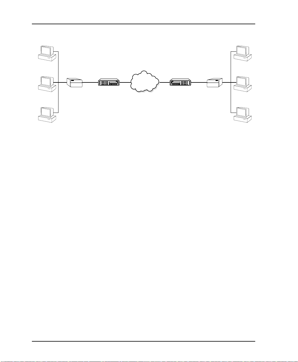
Figure 1-1 on page 1-2 shows a sample point-to-point application
for the DSU III AR.
61202011L1-1 DSU III AR User Manual 1-1
Page 26
Chapter 1. Introduction
ENTER
CANCEL
SHIFT
SHIFT
RS CS T D RD CD AL M TST
DSU III DBU
ENTER
CANCEL
SHIFT
SHIFT
RS CS T D RD CD AL M TST
DSU III DBU
Router DSU III AR DSU III AR
DDS Overview
Digital Data Service (DDS) is a nationwide service that allows
interconnection and transport of data at speeds up to 64 kbps. The
local exchange carriers provide the local loop service to DDS
customers and may provide data for routing Inter-LATA to an
interexchange carrier. In DDS mode, the DSU III AR supports all
DDS service rates yielding DTE rates of 2.4, 4. 8, 9.6, 19.2, 38.4 (sync
or async), 56 and 64 kbps (synchronous). An additional rate of 57.6
kbps is available in async mode. At the DDS service rates of 56 kbps
and 64 kbps, the unit can be configured to run slower DTE rates
(async or sync). Secondary channel operation is supported at all
service rates up to 56 kbps, provid ing terminal rates of 75, 150, 300,
600, 1200, and 2400 bps. The secondary rates available depend on
the DDS service rate configured.
C
DSU III DBU
1 2 3
ENTER
DAEBF
4 5 6
7 8 9
RS CS TD RD CD ALM TST
SHIFT
SHIFT
#0
CANCEL
*
DDS
Network
C
DSU III DBU
1 2 3
ENTER
DAEBF
4 5 6
7 8 9
RS CS TD RD CD ALM TST
SHIFT
SHIFT
#0
CANCEL
*
Router
56 kbps56 kbps
Figure 1-1. Sample Point-to-Point Application for DSU III AR
4-Wire Switched 56 Overview
This switched, 4-wire Digital Data Service allows customers to pay
for data connection only for the time the unit is active. The regional
operating companies provide the 4-wire local loop service to SW56
customers. In SW56 mode the DSU III AR supports DTE rates of
2.4, 4.8, 9.6, 19.2, 38.4 (asynchronous or synchronous) and 56 kbps
(synchronous). An additional DTE rate of 57.6 kbps is available in
asynchronous modes.
1-2 DSU III AR User Manual 61202011L1-1
Page 27

Chapter 2
Installation
UNPACK, INSPECT, POWER UP
Carefully inspect the DSU III AR for any shipping damages. If
damage is suspected, file a claim immediately with the carrier and
contact ADTRAN Customer Service. If possible, keep the origin al
shipping container for use in shipping the DSU III AR for repair or
for verification of damage during shipment.
ADTRAN Shipments Include
The following items are included in ADTRAN shipments of the
DSU III AR:
• DSU III AR unit
• An 8-position modular to 8-position modular cable
• The DSU III AR User Manual
Customer Provides
• Male EIA-232 (st a nda rd 25-pin D-type), or
• Male V.35 interface cable.
Pinouts for the rear connectors are included in Appendix A, Pinouts
on page A-1.
61202011L1-1 DSU III AR User Manual 2-1
Page 28
Chapter 2. Installation
Power Up
Each DSU III AR unit is provided with a captive 8-foot power cord,
terminated by a three-prong plug which connects to a grounded
115 VAC power receptacle. A telco connector is also provided for
interface to the network.
Power to the DSU must be provided from a grounded 115 VAC, 60 Hz
receptacle.
2-2 DSU III AR User Manual 61202011L1-1
Page 29
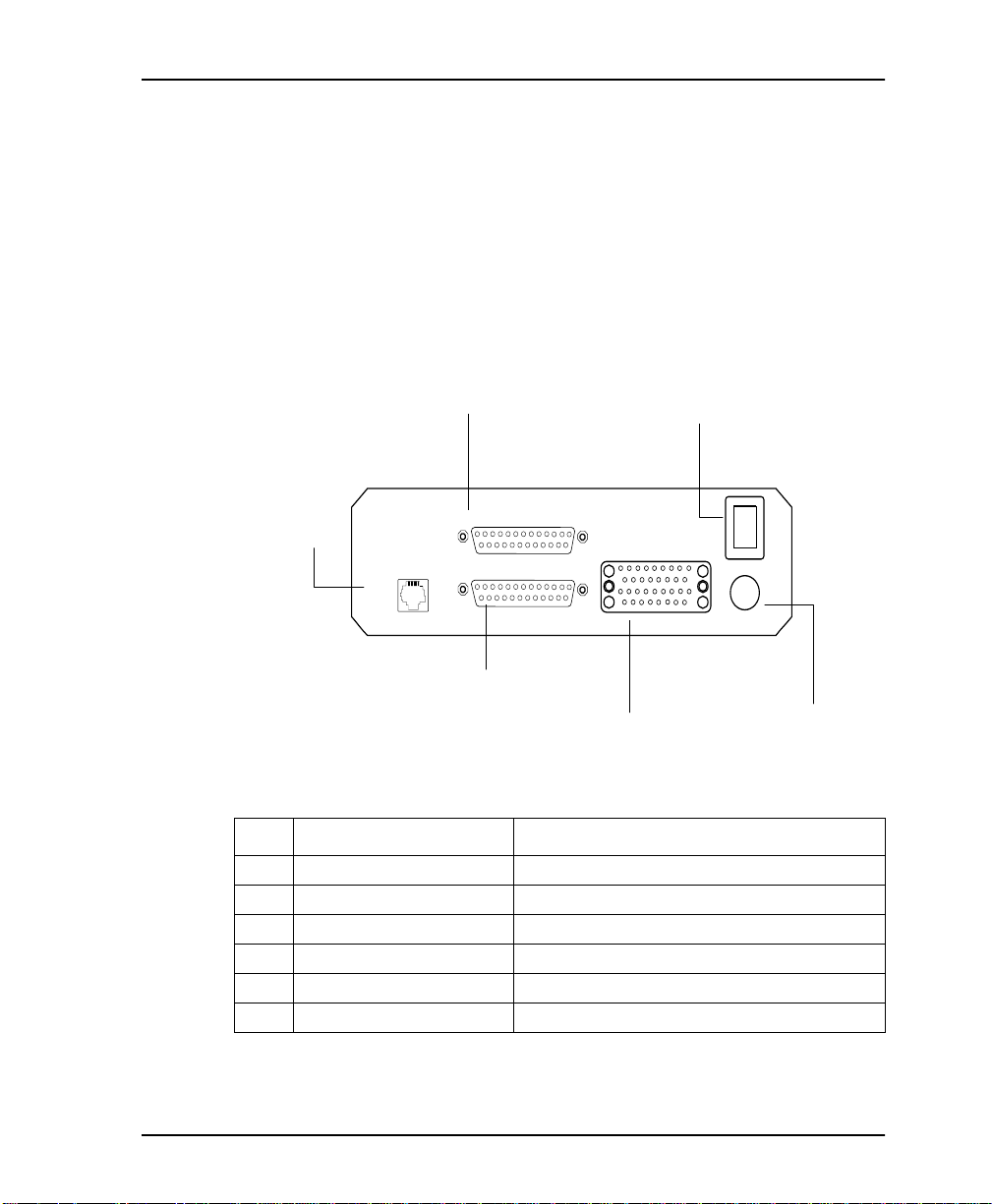
REAR PANEL
The rear panel contains three DTE connectors which provide
primary channel V.35 or EIA-232 , and a s econdary channe l EIA-23 2
port (auxiliary EIA -232). An 8-pin telco jack, a captive power cord,
and a power switch are also located on the rear panel. Pin
assignments for the DT E and network connections are listed in
Appendix A, Pinouts on page A-1. The DSU III AR rear panel is
shown in Figure 2-1.
Chapter 2. Installation
2
Power Switch
115 VAC
60HZ .15A
ON
OFF
6 115 VAC
Connection
3 Telco
Connection
TELCO
4 Primary EIA-232
Connector
1 Aux EIA-232
AUXILIARY EIA-232
PRIMARY V.35
PRIMARY EIA-232
5 Primary V.35
Connector
No. Item Function
1 Auxiliary EIA-232 Secondary channel services
2 Power Switch Used to turn power on or off
3 Telco Connection Connection to the dedicated circuit
4 Primary EIA-232 DTE interface
5 Primary V.35 High speed DTE interface
6 115 VAC Connection Power cord connection
Figure 2-1. DSU III AR Rear View
61202011L1-1 DSU III AR User Manual 2-3
Page 30
Chapter 2. Installation
Network Interface Connection
The DSU III AR has an eight-position modular jack labeled T
The connector is used for connecting to the network when the unit
is configured for either dedicated or switched operation. The pin
assignments for the telco connector are listed in Table A-1 on page
A-1.
DTE Data Connection/Primary DTE
The primary DTE rate is configured from the front panel. The
primary DTE can oper a te in asynchronou s or sync hronous modes
The primary DTE should be connected to either the EIA-232 DTE
connector or the CCITT V.35 DTE connector.
The maximum cable lengths recommended are 50 feet for the EIA-
232. The pin assignments for the primary EIA-232 connector are
shown in Table A-2 on page A-2. The EIA-232 connector works up
to 56 kbps with a low capacitance cable or with the external
transmit clock option selected.
For the CCITT V.35, the maximum cable lengths are 100 feet. The
pin assignments for the V.35 are shown in Table A-3 on page A-3.
The V.35 connector is recommended for use with data rates above
19.2 kbps.
ELCO
.
To prevent possible radio frequency interference emissions, a shielded cable is required.
Secondary Channel Connection
If used, the secondary DTE should be connected to the au xiliary
EIA-232 connector. The pinout for the connector is shown in Table
A-4 on page A-4.
2-4 DSU III AR User Manual 61202011L1-1
Page 31

Chapter 3
Operation
FRONT PANEL MENU STRUCTURE
The DSU III AR uses a multilevel menu approach to access its many
features. All menu operations are displayed in the LCD window.
The opening menu is the access point for all other operations. There
are four Main menu branches: Status, Test, Configuration and Dial.
Each main menu item has several functions and submenus to
identify and access specific parameters.
Main Menu
The following paragraphs briefly describe the main menu's four
branches, displayed on the front panel LCD (see Figure 3-1).
Detailed information is provided in the individual chapters for
each menu branch.
1 = STATUS 2 = TEST
3 = CONFIG 4 = DIAL
Figure 3-1. Main Menu LCD Display
61202011L1-1 DSU III AR User Manual 3-1
Page 32

Chapter 3. Operation
Status
Status is used to display all relevant information for the network
and DTE interfaces. It displays the current operating mode, loop
status, rate of service from the network, DTE data rate and format,
and TR, SR, LL, and RL DTE interface lead status. The display
returns to the status menu when the front panel is not accessed. See
Chapter 12, Viewing Status Information on page 12-1 for more
detailed information.
Test
Test is used to contro l local and re m o t e te s ting. Select local or
remote testing, and select the type of test and test pattern when
required. For more information see Chapter 7, Configuring Test
Options on page 7-1.
Configuration (Config)
Configuration is used to select network and DTE operating
parameters. This menu branch is divided into several chapters for
easier reference. The division includes a brief overview chapter
followed by a separate chapter for each of the five submenus of the
CONFIG branch: Network Configuration on page 5-1, Configuring
DTE Options on page 6-1, Configuring Test Options on page 7-1,
Configuring Dial Options on page 8-1, and Manual Command on page
9-1.
Dial
Dial provides manual dialing functions. Key in a number to dial,
select one of the ten stored numbers, or redial the last dialed
number. This menu is available for use only when AT&T/MCI
SW56 or US SPRINT SW56 is the selected network type. See
Chapter 10, Dial Selection on page 10-1 for more information.
The DIAL option is only available when the unit is configured for a
Switched 56 network type. For more information, see Chapter 10, Dial Selection on page 10-1.
3-2 DSU III AR User Manual 61202011L1-1
Page 33

Basic Menu Travel
Four function keys on the left side of the DSU III AR keypad allow
the various menu branches to be entered, exited, and scrolled
through. The four function keys are defined below.
Enter
Selects a displayed item.
Up Arrow
Scrolls up the submenu items.
Down Arrow
Scrolls down the submenu items.
Cancel
Exits (back one level) from the current branch of the menu.
To choose a menu item, press the corresponding number or alpha
character on the keypad (press
The item flashes on and off to show it is the currently selected
(active) choice. Press the up and down arrow keys to scroll through
the available menu items. Press
Chapter 3. Operation
to activate alpha characters).
Shift
to select the flashing item.
Enter
61202011L1-1 DSU III AR User Manual 3-3
Page 34

Chapter 3. Operation
The following Step/Action Table and Figure 3-2 illustrate how to
select the DSU III AR Loop Rate option.
Step Action
1
To select C
2 To select L
ONFIGURATION
or R
OCAL
EMOTE
ONFIG
(C
), press 3; then
Enter
test, press the corresponding
.
number; then press Enter.
3
4 Choose an item on the submenu such as N
5
6
7
Use the up and down arrows to view submenu items.
ETWORK OP
TIONS
Press 1 to select N
Press 1 to select L
ETWORK OPT
(N
).
ETWORK OPT
OOP RATE
options; then press
then press
;
Enter
.
Enter
When the current network loop rate flashes, you can
.
scroll up or down to view possible options.
8
To select a new loop rate, press the corr esponding num-
.
ber; then press
Enter
.
1=LOOP RATE
1=LOCAL 1=NETWORK OPT. 2=NETWORK ADDR
3=CONFIG 2=DTE OPTIONS 3=REMOTE CONFIG.
2=REMOTE 3=TEST OPTIONS 4=NETWORK TYPE
4=DIAL OPTIONS 5=CLOCK SOURCE
5=MANUAL COMMAND
-
Figure 3-2. Example of Basic Menu Travel
3-4 DSU III AR User Manual 61202011L1-1
Page 35
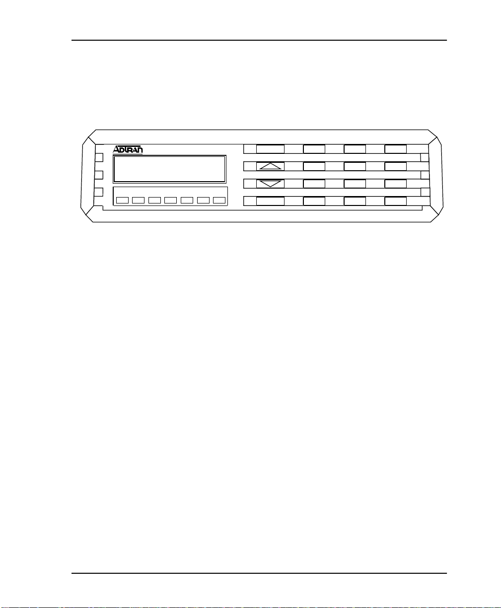
FRONT PANEL
The DSU III AR faceplate is shown in Figure 3-3. Descriptions of
each part of the front panel follow the figure.
Chapter 3. Operation
DSU III AR
RS CS TD RD CD ALM TST
LCD Window
Displays menu items and messages in 2 lines by 16 characters.
Enter
Selects active menu items. To activate a menu item, press the
number of the item. The menu item flashes, indicating it is the
active selection. Press
Numeric Keypad
The numeric keypad contains the numbers 0 through 9 and alpha
characters A through F, which are used to activate menu items and
enter parameters.
A
ENTER
CANCEL
1
45ED6
789
SHIFT
*
Figure 3-3. DSU III AR Front View
to select the menu item.
Enter
B
2
0
C
3
F
QUICK
#
Up and Down Arrows
Use the up and down arrows to scroll through the submenu items
in the current menu. Submenu items appear two at a time in a
circular or wrapping fashion. The submenu items are displayed in
either a forward or reverse pattern.
Cancel
The
key stops the current activity and returns to the
Cancel
previous menu. Repeat until the desired menu level is re ached.
61202011L1-1 DSU III AR User Manual 3-5
Page 36

Chapter 3. Operation
Shift
To enter alpha characters, press
To activate a menu item designated by an alpha character rather
than a number, press
indicating which paramet er is activated. Press
item.
If a key is pressed without using
active instead of the alpha item.
Quick
During most operations, the
main menu. During a test, the
Test menu. In SW56 operation, if the unit is not in test, the
key returns to the D
LED Descriptions
The DSU III AR has seven LED indicators, which are described
below.
before each desired character.
Shift
then the letter. The menu item flashes,
Shift,
Enter
, the numbered item becomes
Shift
key returns the display to the
Quick
key returns to the top of the
Quick
menu.
IAL
to select the
Quick
RS
CS
TD
RD
CD
ALM
TST
3-6 DSU III AR User Manual 61202011L1-1
REQUEST TO SEND
CLEAR TO SEND
TRANSMIT DATA
RECEIVE DATA
CARRIER DETECT
ALARM INDICATION
TEST MODE MANUAL
Page 37

Chapter 4
Configuration Overview
LOCAL AND REMOTE CONFIGURATION
The DSU III AR can be configured locally using the front panel or
remotely by establishing communications with another DSU. The
front panel of the local DSU can then be used to configure the
remote DSU. During remote configuration, the DSU III AR pr ompts
for the remote address before continuing to the C
(CONFIG) menus.
ONFIGURATION
The C
ONFIGURATION
relating to a specific interface or function of the DSU III AR that
requires setup.
1=Network Opt. Network Interface Parameters
2=DTE Options DTE Interface Parameters
3=Test Options Unit Test Options
4=Dial Options Unit Dialing Options
5=Manual Command ADTRAN Specific Commands
The DSU III AR contains four different user profiles (sets of
configurations options) that are stored in read-only memory (see
Appendix C, Default Configuration Profiles on page C-1). The unit is
shipped from the factory with profile number 1 (default
configuration) loaded into the current (nonvolatile configuration)
memory. If profile 1 matches requirements for the system, then no
61202011L1-1 DSU III AR User Manual 4-1
menu consists of a group of five submenus
Page 38

Chapter 4. Configuration Overview
additional configuration is required to put the unit into service. If
profile 1 does not match system requirements, it can be modified,
or one of the other profiles that more closely matches the system
requirements can be loaded into current memory. When a different
profile is loaded, or the existing profile is modified, it is stored in
the current (nonvolatile configuration) memory. The DSU III AR is
then configured with that profile every time power is turned on or
until the unit is reset.
For detailed information on configuration see Chapter 5, Network
Configuration on page 5-1, Chapter 6, Configuring DTE Options on
page 6-1, Chapter 7, Configuring Test Options on page 7-1, Chapter 8,
Configuring Dial Options on page 8-1, and Chapter 9, Manual
Command on page 9-1.
Configuration Methods
The DSU III AR responds to the following methods of
configuration:
• VT-100 Compatible Terminal
•AT Commands
• V.25 Commands
•Front Panel Commands
• Remote Commands from another DSU running SLIP/PPP
protocol.
The DSU III AR provides methods for both local and remote
configuration. These methods are shown in Table 4-1.
Table 4-1. Configuration Methods
Stand Alone
Method Local Remote
AT Commands Yes Yes
V.25 Commands Yes Yes
Front Panel Yes Yes
DATAMATE No Yes
VT-100 Yes Yes
4-2 DSU III AR User Manual 61202011L1-1
Page 39
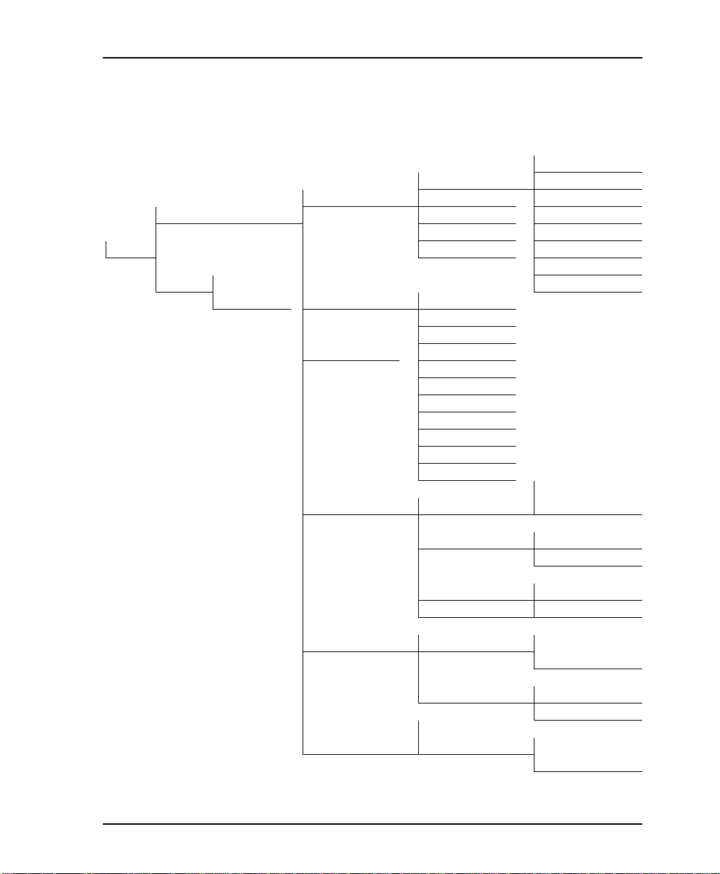
Chapter 4. Configuration Overview
A complete Configuration menu is shown in Figure 4-1; the
Configurati on menu tree with DTE options is shown in Figure 4-2
on page 4-4.
1= AUTO
1= LOOP RATE 2= 2.4K
1= NETWORK OPT. 2= NETWOR K ADDR 3= 4.8K
1= LOCAL 3= REMOTE CONFIG 4= 9.6K
4= NETWORK TYPE 5= 19.2K
3=CONFIG 5= CLOCK SOURCE 6= 38.4K
7= 56K
2= REMOTE ENTER REMOTE 8= 64K
ADDRESS:0 2= DTE OPTIONS 1= DTE RATE
See Figure 4- 2 on page 4- 4 2= CONNECTOR TYPE
for a more detail ed 3= DATA FORMAT
view of this section. 4= DTE CMD OPTION
5= TRANSMIT CLOCK
6= CS OPTIONS
7= ANTI-STREAM
8= CD OPTIONS
9= TR OPTIONS
A= SR OPTIONS
B= AUXILIARY PORT
ENTER TIMEOUT
3= TEST OPTIONS 1= TEST TIMEOUT 0 OFF: 00 SEC
2= RDL EN/DIS 1= RDL IGNORED
2= RDL ACCEPTED
3= EIA LLB EN/DIS 1= DISABLED
4= EIA RLB EN/DIS 2= ENABLED
4= DIAL OPTIONS 1= PHONE NUMBER STORED NUMBER
TO EDIT (1-10):1
2= AUTO ANSWER 1= DISABLED
2= ENABLED
5= MANUAL COMMAND COMMAND COMMAND: HH
VALUE: 00
Figure 4-1. Complete Configuration Menu
61202011L1-1 DSU III AR User Manual 4-3
Page 40

Chapter 4. Configuration Overview
1= DTE RATE Options vary according to loop rate.
2= CONNECTOR TYPE 1= RS-232
2= DTE OPTION S
3= DATA FORMAT 1= ASYNCHRONOUS 1= ASYNC 9 BITS
4= DTE CMD OPTION 2= AT COMMAND SET
5= TRANSMIT CLOCK 1= NORMAL
6= CS OPTIONS 2= FOLLOWS RS
7= ANTI-STREAM 3= TIME 30 SECONDS
2= V.35
2= SYNCHRONOUS 2= ASYNC 10 BITS
3= ASYNC 11 BITS
1= DISABLED
3= V.25 SYNC
4= V.25 BSC/ASYNC
2= EXTERNAL
1= FORCED ON
3= FOLLLOWS CD
4= FOLLOWS RS+ CD
5= OFF WITH LOCD 1= TIMER OFF
2= TIME 10 SECONDS
4= TIME 60 SECONDS
1= FORCED O N
8= CD OPTIONS 2= NORMAL
3= OFF WITH LOCD
9= TR OPTIONS 1= IGNORED
2= IDLE WHEN OFF 1= FORCED ON
3= OFF>ON DIAL #1 2= OFF OOS ONLY
4= OFF>ON DIAL #2 3= OFF LOCD ONLY
A= SR OPTIONS 4= OFF TEST ONLY
5= OFF TEST +OOS
1= EIA-232 6= OFF TEST + LOCD
B= AUXILIARY PORT 2= V.35
Figure 4-2. Configuration Menu with DTE Options
4-4 DSU III AR User Manual 61202011L1-1
Page 41

VT-100 Connection
The DSU III AR can be configured and controlled over a direct EIA232 connection to the Auxiliary Port located on the back of the unit.
To set up the D SU III AR for a VT-100 terminal session, the
following steps are required:
Step Action
1. From the front panel set the connection baud rate. Follow the
menu below to display the appropriate configuration
parameters. Select one of the C
3= CONFIG 1= LOCAL 2= DTE OPTIONS 2= CONNECTOR TYPE
2=REMOTE ENTER ADDRESS 4= DTE CMD OPTION
Chapter 4. Configuration Overview
ONTROL
1= DTE RATE
3= DATA FORMAT
5=TRANSMIT CLOCK
6= CS OPTI ONS
7= ANTI-STREAM
8= CD OPTIONS
9= TR OPTIONS
A= SR OPTIONS
B= AUXILIARY PORT
baud rates.
1= 1.2K AT_CMD
2= 75 SEC
3= 150 SEC
4= 300 SEC
5= 600 SEC
6= 1.2K SEC
7= 2.4K SEC
8= OFF
9= 300 CONTROL
A= 1.2K CONTROL
B= 2.4K CONTROL
C= 9.6K CONTROL
2. After the baud rate is selected, a passcode prompt is displayed.
Enter the desired passcode, or press
to accept the 123
Enter
default.
3. Configure the VT-100 emulator with the appropriate baud rate,
8
DATA BITS
O PARITY BITS
, N
STOP BIT
, 1
, and N
O FLOW
control
(8N1). Refer to the VT-100 emulator documentation for details
on configuration.
4. Connect the VT-100 terminal to the female RS-232 connector,
labeled A
5. Press
UXILIARY PORT
<Enter>
on the VT-100 terminal and a passcode prompt is
, located on the back of the unit.
displayed. Enter the passcode from step 2.
61202011L1-1 DSU III AR User Manual 4-5
Page 42

Chapter 4. Configuration Overview
AT Commands
The DSU III AR can be configured and controlled with in-band AT
commands from an asyn chronous DTE por t jus t as modems a re.
To exit the data mode and enter the command mode, the
asynchronous DTE device must transmit a proper escape sequence
or three pluses (+++) to the DSU III AR. A specified time delay
must occur between the last data character and the first escape
sequence character. This is the guard time delay, and it can be
changed by w ritin g a va lue to the S12 re giste r. The default val ue for
the guard time is one second. For a valid escape sequence to occur,
the DTE must transmit the escape code character three times in
succession with delay between each character being less than the
guard time.
Once the command mode is entered, AT commands can be
transmitted to the DSU III AR to configure most of the options or
initiate tests to check both the DSU III AR and the network
connections. All command lines must begin with the AT attention
code in either capital or lower case letters. The command that
follows must match the case of the attention code.
The command line may contain a single co mmand or a series of
commands after the AT attention code. When a series of commands
is used, the individual commands may be separated with spaces for
readability. The maximum length for a command line is 40
characters. Each command line is executed by the DSU III AR upon
receipt of a terminating character. The default terminating
character is a carriage return (ASCII 013), but it can be changed by
writing a different value to register S3.
Before the terminating character is transmitted, the command line
can be edited by using the backspace character (ASCII 008) to erase
errors so the proper commands can be entered.
Valid AT commands for the DSU III AR are listed in Appendix B,
AT Commands on page B-1.
4-6 DSU III AR User Manual 61202011L1-1
Page 43

V.25 Bis Commands
When configured for the V.25 bis option, the DSU III AR accepts inband dialing an d configuration commands from both sy nchronous
and asynchronous DTE ports.
The V.25 bis option supports the following protocols:
• SDLC (Synchronous Data Link Control)
• BI-SYNC
•ASYNCHRONOUS
SDLC Option
Character Format
• Data bits - 8
•Parity bit - Ignored
Command Structure
[F][A][C][V.25 bis COMMAND][FCS][F]
Chapter 4. Configuration Overview
The address field [A] is FFH. The control field [C] is set to 13H
except for cases of multi-frame responses. For this case, the control
field is set to 03H in all but the last frame. The 03H in the cont rol
field indicates that other frames are to follow while the 13H in the
control field indicates the final frame.
Bi-Sync Option
Character Format
• Data bits - 7
•Parity bit - Odd
Command Structure
[SYN][SYN][STX][V.25 bis COMMAND][ETX]
61202011L1-1 DSU III AR User Manual 4-7
Page 44

Chapter 4. Configuration Overview
Asynchronous Option
Character Format
Start bit - 1
Data bits - 7
Parity bit - Even
Stop bit - 1
Command Structure
[V.25 bis COMMAND][CR][LF]
Command Descriptions
The ADTRAN V.25 bis command set is a subset of the CCITT V.25
bis command set. In addition to the CCITT commands supported,
ADTRAN has added configuration commands for both local and
remote DSUs.
The ADTRAN V.25 bis command set follows:
CIC Connect incoming call
CNL Configuration local
CNR Configuration remote
CRN Call request with number
CRS Call reque st us ing s tor ed num ber
DIC Disregard incoming call
PRN Program number
RLN Request list of numbers
4-8 DSU III AR User Manual 61202011L1-1
Page 45

Chapter 4. Configuration Overview
The following list contains possible responses to V.25 bis
commands:
VAL Valid V.25 command processed
CFIET Call failed on switched network - busy detected
CFIDE Call failed on switched network - no wink de-
tected
CFINS Call failed - no dial string in specified re gi ste r
INVCU Unknown command detected
INVPS Invalid parameter syntax
INVPV Invalid parameter value
INVBL Invalid local pass wo rd
INVBM Invalid remote passwor d
INC Incoming call
CNX Call connected
If verbose responses are disabled (A TV0), the following list of threecharacter responses are the only ones returned:
VAL Valid V.25 command processed
INV Invalid command received
CFI Call failed
INC Incoming ca ll
CNX Call connected
Syntax and Possible Responses
CIC (Connect Incoming Call)
This command causes the DSU to go on-line. For dial backup units,
this command hangs up the dial backup line and initiates an
attempt to reestablish the main (DDS) line. There are no parameters
associated with this command. Possible indications include VAL,
CNX, and CFIxx.
61202011L1-1 DSU III AR User Manual 4-9
Page 46

Chapter 4. Configuration Overview
CNL (Configuration Local)
This command is used to pass AT commands to the local modem
via the V.25 bis command processor. This allows the DSU III AR to
be configured with A T commands via a synchronous interface. The
command has the following format:
CNL[LOCAL PASSWORD;]AT[ONE OR MORE AT COMMANDS]
A local pass word may not be r e q uired, depe nd i n g on the prese nt
configuration of the unit . Responses to CNL commands are
returned in the data format currently configured. Possible
responses include VAL and INVn.
CNR (Configuration Remote)
This command is used to pass AT commands over the network to
the remote DSU via the V.25 bis command processor. This allows a
remote DSU III AR to be configured from a synchronous interface.
The command's format is as follows:
CNR[REMOTE PASSWORD;]AT[ONE OR MORE AT COMMANDS]
The remote password may or may not be required depending on
the present configuration of the remote unit. Responses to the CNR
commands are returned in the data format currently configured.
Possible responses include VAL and INVn.
Switched 56 Operation
CRN (Call Request with Number)
When the DSU III AR is configured for SW56 operation, the CRN
command causes the DSU to dial the supplied number. The
command's format follows:
CRN[NUMBER TO BE DIALED]
If no number is included in the command, the number stored in
dial register number 1 is dialed. If no number is provided and no
number is stored in dial register number 1, the DSU III AR
responds with the call failure indication CFINS (Call Failure
Indication Not Stored).
For a DBU unit, this command initiates dialing on the backup
circuit. If the number suppli ed contains non-dialable digits, they
4-10 DSU III AR User Manual 61202011L1-1
Page 47

Chapter 4. Configuration Overview
are ignored and only the dialable digits are dialed. Possible
responses include VAL, CNX, and CFIxx.
CRS (Call Request Using Stored Number)
The CRS command causes the DSU III AR to dial the number
stored in the specified register. The format of this command is as
follows:
CRS [OPTIONAL SPACE][REGISTER NUMBER 1-10]
If this command is issued without the register number parameter,
the INVPS (Invalid Parameter Synta x ) response is issued. If this
command is issued and the register parameter is not in the valid
range for dialing registers, the INVPV (Invalid Parameter Value)
response is returned. Other responses include VAL, CNX, and
CFIxx.
DIC(Disregard Incoming Call)
This command causes the V.25 bis processor to return to command
mode even if there is an incoming call pending. This allows local
commands to be issued and incoming calls to be ignored. Ther e are
no parameters associated with this command. The DSU responds
with VAL.
PRN (Program Number)
This command stores the supplied number into the specified
register. Th e com mand has the following format:
PRN REGISTER NUMBER;[NUMBER TO BE STORED]
If this command is entered with no parameters, the INVPS
response is returned. If no register number is included in the
command or if it is invalid, the INVPV response is returned. This
response is also returned if the number to be stored contains invalid
characters. The characters 1, 2, 3, 4, 5, 6, 7, 8, 9, 0, P, T, and & are
valid dial characters. If no digits ar e is sued wi th this command, the
specified register is cleared. The DSU responds with VAL.
61202011L1-1 DSU III AR User Manual 4-11
Page 48

Chapter 4. Configuration Overview
RLN (Request List of Numbers)
This command causes the DSU III AR to return the number stored
in the specified register. The format of this command follows:
RLN [REGISTER NUMBER]
If the register number is invalid, the INVPV response is returned.
When a correct register number is entered, the following response
is returned:
LSN [REGISTER NUMBER];[NUMBER STORED]VAL
If no register number is present in the command, the DSU III AR
responds with a list of all the registers and the stored numbers. This
list is followed by the VAL response.
4-12 DSU III AR User Manual 61202011L1-1
Page 49

Chapter 5
Network Configuration
NETWORK OPTIONS
Loop Rate
ETWORK OPTIONS
The N
operation of the DSU III AR.
Once a parameter is set, C
before returning to the active menu.
The Loop Rate option sets the loop operating speed. The unit
should be set to the rate required by the DDS Service. The DSU III
AR also supports subrate DTE data over a 56 kbps or 64 kbps loop.
The loop rate must be set independently of the DTE rate.
The default factory setting is A
DSU will automatically attempt to adapt to the loop rate. Since 64k
and 56k secondary channels look identical on the network, the DSU
III will adapt to 56k secondary channel for either loop rate. If the
loop rate is known, select the rate from the menu. The various loop
rates and format selections are listed in Figure 5-1 on page 5-2. The
equivalent AT commands that perform the same configuration
functions are shown in Table 5-1 on page 5-2.
Eight loop rate selections are available (shown in Figure 5-1). After
selecting any loop rate other than A
secondary channel is available. The secondary channel rate is
determined by the current loop rate.
configuration parameters control the loop
OMMAND ACCEPTED
UTO
. When configured to A
UTO
is displayed bri efly
or 64
KBPS
the option for a
UTO
, the
61202011L1-1 DSU III AR User Manual 5-1
Page 50
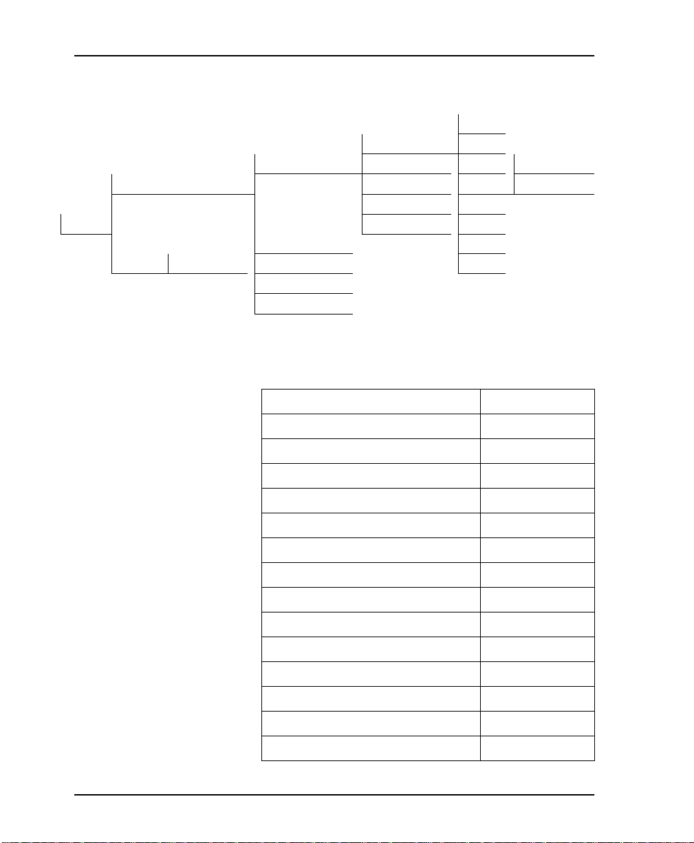
Chapter 5. Network Configuration
1= AUTO
1= LOOP RATE 2= 2.4K
1=NETWORK OPT. 2= NETWORK ADDR 3= 4 .8K 1= NO SEC CH
1=LOCAL 3= REMOTE CONFIG 4= 9.6K 2= SEC CHANNEL
4= NETWORK TYPE 5= 19.2K
3=CONFIG 5= CLOCK SOURCE 6= 38.4K
2=DTE OPTIONS 7= 56K
2=REMOTE ENTER ADDRESS 3=TEST OPTIONS 8= 64K
4=DIAL OPTIONS
5=MANUAL COMMAND
Figure 5-1. Setting Loop Rate Options
Table 5-1. Loop Rate Commands
Front Panel AT Command
AUTO %B0
2.4K with no secondary channel %B1
4.8K with no secondary channel %B2
9.6K with no secondary channel %B3
19.2K with no secondary channel %B4
38.4K with no secondary channel %B5
56K with no secondary channel %B6
64K clear channel %B7
2.4K with secondar y cha nnel %B9
4.8K with secondar y cha nnel %B10
9.6K with secondar y cha nnel %B11
19.2K with secondary channel %B1 2
38.4K with secondary channel %B1 3
56K with secondary channel %B14
5-2 DSU III AR User Manual 61202011L1-1
Page 51
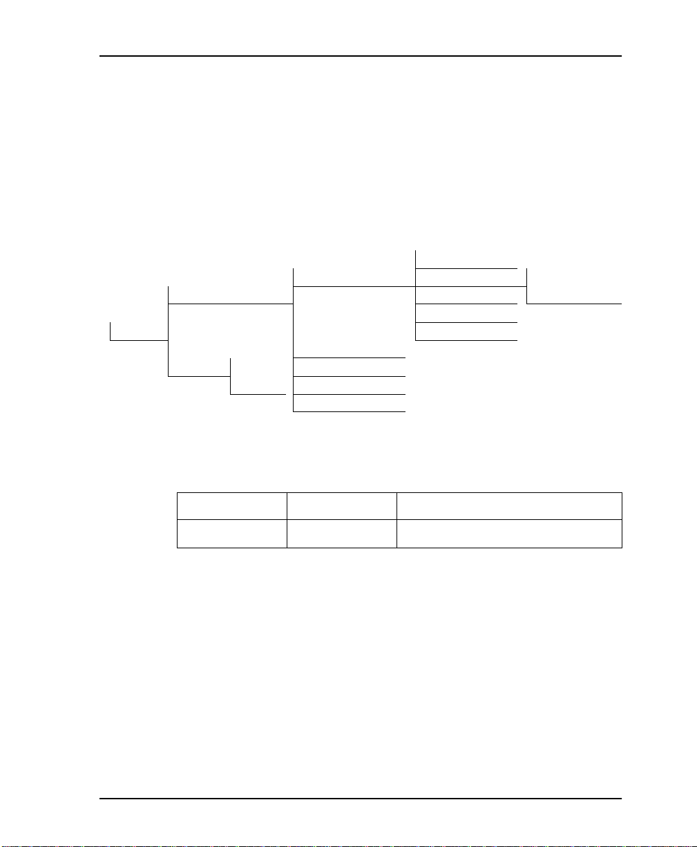
Chapter 5. Network Configuration
Network Address
A two-digit decimal address can be assigned to each DSU III AR.
This addressing capability makes it possible to perform remote
configuration and testing in point-to-point and multi-drop
networks. Figure 5-2 shows the menu path used to change the
network address. The factory default address setting is 0. Table 5-2
shows the AT commands used to set the network address.
1=LOOP RATE
1=NETWORK OPT. 2=NETWORK ADDR ENTER NETWORK
1=LOCAL 3=REMOTE CONFIG ADDRESS: 0
4=NETWOR K TY P E
3=CONFIG 5=CLOCK SOURCE
2=DTE OPTIONS
2 =REMOTE ENTER 3=TEST OPTIONS
ADDRESS 4=DIAL OPTIONS
5=MANUAL COMMAND
Figure 5-2. Setting the Network Address
Table 5-2. Network Address Command
Front Panel AT Command Description
XX (Decimal) _N=xx A ss i gns a 2-digit Network Address
61202011L1-1 DSU III AR User Manual 5-3
Page 52
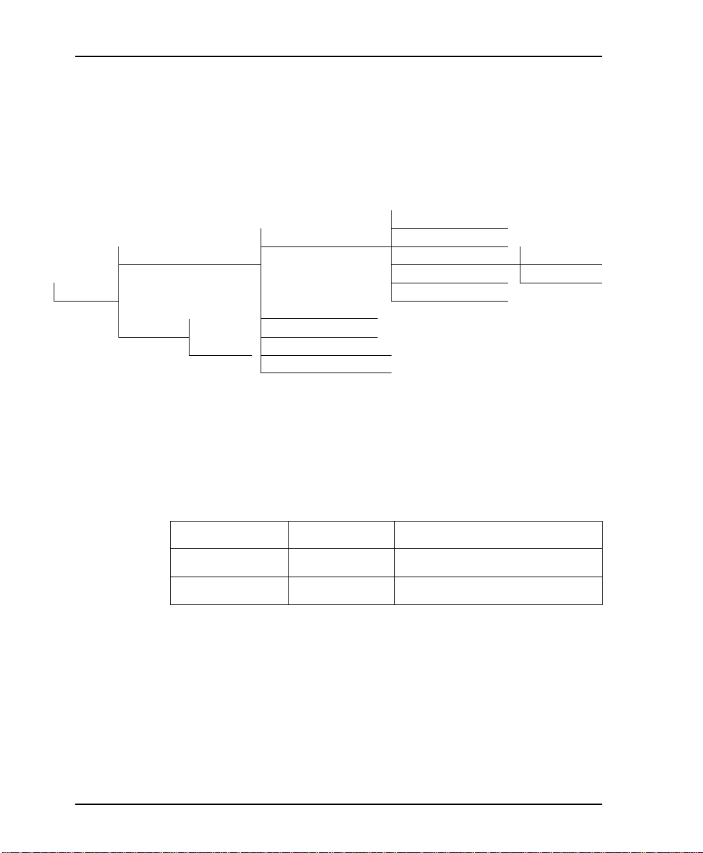
Chapter 5. Network Configuration
Remote Configuration
This option sets up the DSU III AR to accept or reject remote
configuration commands. Figure 5-3 sho ws t he m enu pat h for
enabling/disabling remote configuration. The factory
default setting is E
1= NETWORK OPT. 2= NETWORK ADDR
1= LOCAL 3= REMOTE CONFIG 1= DISABLED
3= CONFIG 5= CLOCK SOURCE
2= DTE OPTIONS
2= REMOTE E NTER 3= TEST OPTIONS
ADDRESS 4= DIAL OPTIONS
5= MANUAL COMMAND
NABLED
Figure 5-3. Enabling/Disabling Remote Configuration
.
1= LOOP RATE
4= NETWORK TYPE 2= ENABLED
Table 5-3 shows the equivalent AT commands used to enable or
disable remote configuration.
Table 5-3. Remote Configuration Commands
Front Panel AT Command Description
1=DISABLE &P4 Disable Remote Configuration
2=ENABLE &P5 Enable Remote Configu ra tion
5-4 DSU III AR User Manual 61202011L1-1
Page 53

Chapter 5. Network Configuration
Network Type
This option configures the DSU III AR for the specific type of
network being used. The choices are D
SW56. The facto ry default setting is
and US S
D
EDICATED
1= LOCAL 3= REMOTE CONFIG 1= DEDICATED
3=CONFIG 5= CLOCK SOURCE 3= US SPRINT SW 56
2= REMOTE ENTER 3= TEST OPTIONS
ADDRESS 4= DIAL OPTIONS
PRINT
(see Figure 5-4).
1= LOOP RATE
1= NETWORK OPT. 2= NETWORK ADDR.
4= NETWORK TYPE 2= AT&T/MCI SW 56
2= DTE OPTIONS
5= MANUAL COMMAND
Figure 5-4. Setting Network Type Options
EDICATED
, AT&T/MCI SW56,
SW56 is selected, the Main
When AT&T/MCI SW56 or US S
menu displays the D
IAL
selection.
PRINT
Table 5-4 shows the equivalent AT commands that perform the
same configuration functions.
Table 5-4. Network Type Commands
Front Panel AT Command Description
1=DEDICATED &L0 A ny 4-wire DDS Network
2=AT&T/MCI &L1 AT&T/MCI Switched 56 Service
3=US SPRINT &L2 US SPRINT Switched 56 Service
61202011L1-1 DSU III AR User Manual 5-5
Page 54

Chapter 5. Network Configuration
Clock Source
LOCK SOURCE
The C
III AR internal circuitry. The choices are F
ASTER
M
. The factory default setting is F
5-5).
1= NETWORK OPT. 2= NETWORK ADDR
1= LOCAL 3= REMOTE CONFIG
3=CONFIG 5= CLOCK SOURCE 2= FROM NETWORK
2= DTE OPTIONS
2= REMOTE ENTER 3= TEST OPTIONS
ADDRESS 4= DIAL OPTIONS
5= MANUAL COMMAND
When operating on a DDS network, the timing should be from the
most stable clock source, usually F
point private network, one DSU III AR must be set for M
the other set for FROM
commands for setting the clock source.
options specify the timing source for the DSU
ROM NETWORK
ROM NETWORK
1= LOOP RATE
4= NETWORK TYPE 1= MASTER
and
(see Figure
Figure 5-5. Setting the Clock Source
N
ETWORK
ROM NETWORK
. T able 5-5 shows the equivalent AT
. On a point-to-
ASTER
and
When the DSU III AR is set as the master clock source, it will
default to its internal oscillator as the clock reference. T o enable the
External DTE port as the reference clock for the circuit, see Chapter
6, Configuring DTE Options on page 6-1.
Table 5-5. Setting the Clock Source
Front Panel AT Command Descriptio n
1=MASTER _X0 DSU is the master timing source
2=FROM NETWORK _X1 Network RX Signal is timing source
5-6 DSU III AR User Manual 61202011L1-1
Page 55

Chapter 6
Configuring DTE Options
DTE OPTIONS
The DTE O
parameters that control the operation of the DSU III AR's DTE
Interface such as the DTE rate, connector type, data format, DTE
command options, transmit clock, CS options, ant i-stream, and CD
options.
PTIONS
menu is used to select the configuration
61202011L1-1 DSU III AR User Manual 6-1
Page 56
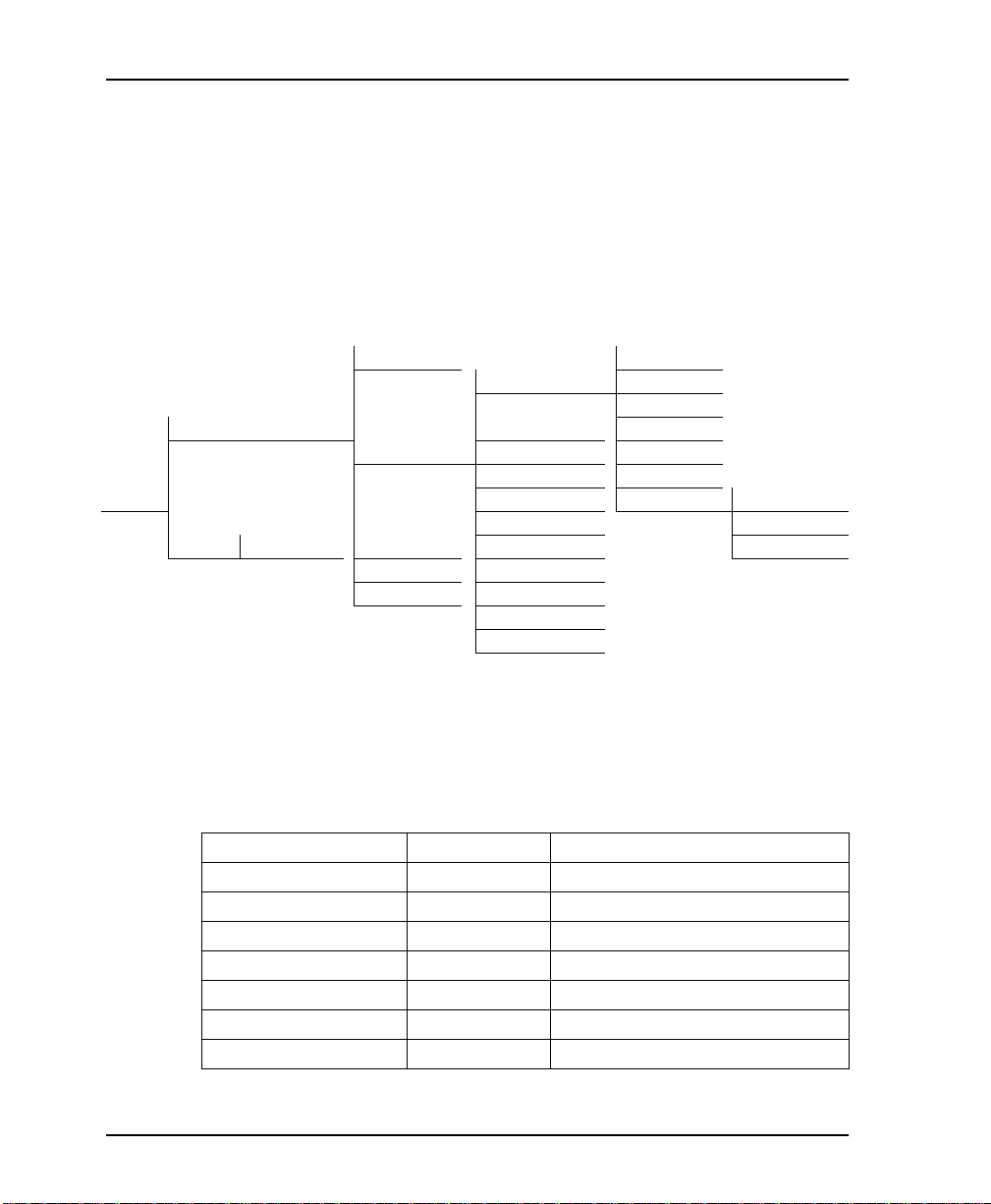
Chapter 6. Configuring DTE Options
DTE Rate
The selectable DTE rates over a 56 or 64 kbps loop with no
secondary channel are shown in Figure 6-1. If a slower loop rate is
selected, then the DTE rate automatically matches the loop rate. If
an attempt is made to set the DTE rate for l oop rates slower than 56
kbps, the DSU III AR briefly displays DTE R
ETWORK
N
setting is S
ATE SAME AS THE
before returning to the status screen. The factory default
AME AS LOOP
.
1= NETWORK OPT.
1= DTE RATE 2= 4.8K
1= LOCAL 2= CONNECTOR TY PE 4= 19.2K
2= DTE OPTIONS 3= DATA FORMA T 5= 38.4K
4= DTE CMD OPTION 6= 56K/57.6K For 64Kbps Loop
3=CONFIG 5= TRANSMIT CLOCK 7= SAME AS LOOP 1= SCRAMBLER OFF
6= CS OPTIONS 2= SCRAMBLER ON
2= REMOTE ENTER ADDRESS 3= TEST OPTIONS 7= ANTI-STREAM 3= DATA INVERT
4= DIAL OPTIONS 8= CD OPTIONS
5= MANUAL 9= TR OPTIONS
A= SR OPTIONS
B= AUXILIARY PORT
1= 2.4K
3= 9.6K
Figure 6-1. DTE Rates for 56 or 64 kbps Loop Rate with No Secondary Channel
The equivalent AT commands for setting the DTE rate for a 56 kbps
loop rate with no secondary channel are shown in Table 6-1.
Table 6-1. DTE Rate AT Commands
Front Panel AT Co mman d Description
1=DTE 2.4K %K3 DTE rate 2.4K sync and async
2=DTE 4.8K %K4 DTE rate 4.8K sync and async
3=DTE 9.6K %K5 DTE rate 9.6K sync and async
4=DTE 19.2K %K6 DTE rate 19.2K sync and async
5=DTE 38.4K %K7 DTE rate 38.4K sync and async
6=DTE 56K/57.6K %K8 DTE rate 56K sync or 57.6 async
7=SAME AS LOOP %K9 DTE rate same as loop speed
6-2 DSU III AR User Manual 61202011L1-1
Page 57

Chapter 6. Configuring DTE Options
If the DSU III AR is set for a loop rate of 56 kbps with secondary
channel, then S
in Figure 6- 2. The factory def au lt setting is S
1= NETWORK OP T . 1= 2.4K
1= LOCAL 2= DTE OPTIONS 1= DTE RATE 2= 4.8K
3=CONFIG 4= DTE CMD O PTION 5= 38.4K 1= SCRAMBLER OFF
2= REMOTE ENTER 3= TEST OPTIONS 6= CS OPTIONS 7= SAME AS LOOP 3= DATA INVERT
ADDRESS 4= DIAL OPTIONS 7= ANTI-STREAM
5= MANUAL 8= CD OPTIONS
CRAMBLER ON/OFF
2= CONNECTOR TYPE 3= 9.6K
3= DATA FORMAT 4= 19.2K
5= TRANSMIT CLOCK 6= 56K/57.6K 2= SCRAMBLER ON
9= TR OPTIONS
A= SR OPTIONS
B= AUXILIARY PORT
options are available as shown
CRAMBLER OFF
56 Kbps Secondary
Channel Loop Rates
.
Figure 6-2. DTE Rates for 56 kbps Secondary Channel and 64 kbps Loop Rates
Table 6-2 shows the equivalent AT commands for setting
CRAMBLER ON/OFF
S
for loop rates of 56 kbps with secondary
channel and 64 kbps.
Table 6-2. Scrambler On/Off AT Commands
Front Panel AT C omm and Description
1=SCRAMBLER OFF _F0 DTE data scrambler disabled
2=SCRAMBLER ON _F1 DTE data scrambler enabled
3=DATA INVERT _F2 DTE data invert enabled (56 kbps second-
ary channel Loop Rate only). LBE codes
from DTE suppressed (64 kbps only).
61202011L1-1 DSU III AR User Manual 6-3
Page 58

Chapter 6. Configuring DTE Options
For point-to-point operation at 56 kbps with secondary channel, the network requires that the primary and secondary channel data not be all zeros
simultaneously. For HDLC protocol applications, this constraint can be
eliminated by select ing either the D
BLER ON
option. The factory default setting is S
For 64 kbps clear channel operation, there is a possibility that the DTE
data sequences might mimic network loop maintenance functions and erroneously cause other network elements to activate loopbacks. To prevent
this, the
S
for both the local and remote DSU III AR.
CRAMBLER ON
or
S
UPPRESS
ATA INVERT
LBE
-
option or the S
CRAMBLER OFF
CRAM
.
option should be selected
6-4 DSU III AR User Manual 61202011L1-1
Page 59

Chapter 6. Configuring DTE Options
Connector Type
ONNECTOR TYPE
The C
primary channel connectors is used to connect to the DTE. Figure
6-3 shows the menu path used to set the connector type. The
factory default setting is V.35. There are no AT commands available
to set the connector ty pe.
1= LOCAL 1=DTE RATE 1= RS-232
3=CONFIG 4= DTE CMD OPTION
2= REMOTE ENTER ADDRESS 3= TEST OPTIONS 6= CS OPTIONS
option is used to specify which of the
1= NETWOR K OPT.
2= DTE OPTIONS 2= CONNECTOR TYPE 2= V.35
3= DATA FORMAT
5= TRANSMIT CLOCK
4= DIAL OPTIONS 7= ANTI-STREAM
5= MANUAL 8= CD OPTIONS
9=TR OPTIONS
A= SR OPTIONS
B=
AUXILIARY PORT
Figure 6-3. Selecting the Connector Type
61202011L1-1 DSU III AR User Manual 6-5
Page 60

Chapter 6. Configuring DTE Options
Data Format
ATA FORMAT
The D
SYNCHRONOUS
or A
factory default setting is S
SYNCHRONOUS
A
option is used to select either the S
mode of operation for the DTE interface. The
YNCHRONOUS
is chosen, the length of the data bytes must be
selected.
1= NETWORK OPT.
1= DTE RATE 1= ASYNC 9 BITS
2= DTE OPTIONS 2= CONNECTOR TYPE 1= ASYNCHRONOUS 2= ASYNC 10 BITS
1= LOCAL 3= DATA FORMAT 2 = SYNCHRONOUS 3 = ASYNC 11 BITS
4= DTE CMD OPTION
5= TRANSMIT CLOCK
3=CONFIG 6= CS OPTIONS
7= ANTI-STREAM
2= REMOTE ENTER 3= TEST OPTIONS 8= CD OPTIONS
ADDRESS 4= DIAL OPTIONS 9= TR OPTION S
5= MANUAL COM. A= SR OPTIONS
B= AUXILIARY PORT
Figure 6-4. Selecting Asynchronous or Synchronous Data Format
Table 6-3 shows the AT commands that can be used to set the D
F
ORMAT
.
Table 6-3. Data Format Commands
YNCHRONOUS
(see Figure 6-4). If
ATA
Front Panel AT Command Description
1=ASYNCHRONOUS &Q0 Always asynchronous
2=SYNCHRONOUS &Q2 Always synchronous
For asynchronous options, select the length of the data bytes.
1=ASYNC 9 BITS N/A 9 bits including start, stop, parity
2=ASYNC 10 BITS N/A 10 bits including start, stop, parity
3=ASYNC 11 BITS N/A 11 bits including start, stop, parity
6-6 DSU III AR User Manual 61202011L1-1
Page 61

DTE Command Option
Chapter 6. Configuring DTE Options
The DTE C
OMMAND
option is used to enable AT commands from
the DTE, enable V.25 bis SDLC (Synchronous Data Link Control)
commands, enable V.25 (Bisync and Async), or disable all DTE
command modes (see Figure 6-5).
1= NETWORK OP T.
1= LOCAL 1= DTE RATE
2= CONNECTOR TYPE
3= DATA FORMAT
3=CONFIG 2= DTE OPTIONS 4= DTE CMD OPTION 1= DISABL ED
5= TRANSMIT CLOCK 2= AT COMMAND SET
2 =REMOTE ENTER 3= TEST OPTIONS 6= CS OPTIONS 3= V.25 SYNC
ADDRESS 4= DIAL OPTIONS 7= ANTI-STREAM 4= V.25 BSC/ASYNC
5= MANUAL COM. 8= CD OPTIONS
9= TR OPTIONS
A= SR OPTIONS
B= AUXILIARY PORT
Figure 6-5. Selecting DTE Command Option
mode (idle in SW56 mode, force d
When the unit is in DTE CMD O
with TR option, or from escape seque nce in AT mode) with AT C
S
ET
or V.25 S
F
ORMAT
use V.25 B
SYNC
A
commands for asynchronous data format.
YNC
selected, the DTE fo rmat is indepen den t of the D
option. However, if V.25 BSC/A
ISYNC
(BSC) commands for synchronous data format or V.25
PTION
SYNC
is selected, the unit will
OMMAND
ATA
61202011L1-1 DSU III AR User Manual 6-7
Page 62

Chapter 6. Configuring DTE Options
Transmit Clock
RANSMIT CLOCK
The T
used to transfer data from the DTE into the DSU III AR. Figure 6-6
shows the menu path used to set the T
factory default in N
1= LOCAL 3= DATA FORMAT
3= CONFIG 6= CS OPTIONS 2= EXTERNAL
2= REMOTE ENTER ADDRESS 3= TEST OPTIONS 8= CD OPTIONS
option is used to select the source of the clock
RANSMIT CLOCK
ORMAL
.
1= NETWOR K OPT.
1= DTE RATE
2= CONNECTOR TYPE
4= DTE CMD OPTION
2= DTE OPTIONS 5= TRANSMIT CLOCK 1= NORMAL
7= ANTI-STREAM
4= DIAL OPTIONS 9= TR OPTIONS
5= MANUAL COM. A= SR OPTIONS
B= AUXILIARY PORT
option. The
Figure 6-6. Transmit Clock Options
Table 6-4 shows the A T commands used to set the T
RANSMIT CLOCK
option.
Table 6-4. Transmit Clock AT Commands
Front Panel AT Command Description
1=NORMAL &X0 TX clock from DSU selected
2=EXTERNAL &X1 ETC clock from DTE selected
XTERNAL CLOCK
The E
M
ASTER CLOCK
under DTE Options connector type. The C
ETWORK OPTIONS
N
option allows the DSU III AR to accept
timing from the External DTE Port as defined
must also be set to M
LOCK SOURCE
ASTER
as noted in Network
under
Configuration on page 5-1.
6-8 DSU III AR User Manual 61202011L1-1
Page 63

Chapter 6. Configuring DTE Options
XTERNAL CLOCK
The E
option is normally used in modem tail circuit
applications. See Appendix E, DSU to DSU Tail Circuit on page E-1
for information about the DSU to modem interconnect diagram for
this application.
The E
XTERNAL CLOCK
option is also recommended when the
EIA-232 connector is used for 56 kbps and 64 kbps applications. A
special DSU cable diagram for this application is shown in
Appendix D, EIA-232 Co nn e ctor on page D-1. Using this option and
special cable eliminates data errors caused by excessive delays in
the DTE transmit clock receiver and transmit data driver.
61202011L1-1 DSU III AR User Manual 6-9
Page 64

Chapter 6. Configuring DTE Options
CS Options
The C
LEAR TO SEND
(CS O
PTIONS
) menu is used to select one of five
different control modes for the CS lead. Figure 6-7 shows the menu
path used to access the CS O
setting is F
1= LOCAL 1= DTE RATE
3=CONFIG 4= DTE CMD OPTION 1= FORCED ON 1= CS DELA Y SHORT
2= REMOTE ENTER 3= TEST OPTIONS 6= CS OPTIONS 3= FOLLOWS C D
ADDRESS 4= DIAL OPTIONS 7= ANTI-STREAM 4= FOLLOWS RS+CD 1= CS DELAY SHORT
OLLOWS
1= NETWORK OPT.
2= DTE OPTIONS 2= CONNECTOR TYPE
5= MANUAL COM. 8= CD O PTIONS 5= OFF THE LOCD 2= CS DELAY LONG
RS with CS D
3= DATA FORMAT
5= TRANSMIT CLOCK 2= FOLLOW RS 2= CS DELAY LONG
9= TR OPTIONS
A= SR OPTIONS
B= AUXLILARY PORT
PTIONS
menu. The default factory
ELAY SHORT
.
Figure 6-7. Selecting CS Options
If one of the options chosen involves request to send (RS), then the
delay from RS to CS must be sele cted . Table 6-5 on page 6- 11 shows
the AT C
OMMANDS
used to set the CS O
PTIONS
.
6-10 DSU III AR User Manual 61202011L1-1
Page 65

Chapter 6. Configuring DTE Options
Table 6-5. CS Options AT Commands
Front Panel AT Command Description
1=FORCED ON &R0 CS always on.
2=FOLLOWS RS &R1 CS on wit h RS afte r del ay ; off whe n RS
or if DSU cannot pass data.
3=FOLLOWS CD &R2 CS off when CD goes off or if DSU can-
not pass data.
4=FOLLOWS RS+CD &R3 CS follows RS after d ela y and also off if
CD off. If CD goes off after RS is on, DSU
III AR will turn off CS but continue to pass
data until RS goes off. CS also off if DSU
cannot pass data.
5=OFF WITH LOCD &R4 Off 5 sec after LOCD. Valid only in SW56
mode. CS is forced on but will turn off for
5 seconds after a call is disconn ected.
For RS options, se lec t the RS to CS delay length.
1=CS DELAY SHORT _D0 Short Dela y from RS to CS selected.
2=CS DELAY LONG _D1 Long Delay from RS to CS selected.
Specified times for the short and long delays at the different
operating speeds are shown in Table 6-6.
Table 6-6. Short and Long Delays at Different Operating Speeds
Rate Short Option Long Option Tolerance
Add to Maximum Time
for Secondary Channel
64K 1.1ms 16.1ms ±.4ms
56K 1.1ms 16.1ms ±.4ms .33ms
38.4K 1.5ms 16.5ms ±.4ms .63ms
19.2K 1.5ms 16.5ms ±.4ms 1.25ms
9.6K 1.5ms 16.5ms ±.4ms 2.5ms
4.8K 1.9ms 16.9ms ±.7ms 5.0ms
2.4K 3.8ms 18.8ms ±1.3ms 10.0ms
61202011L1-1 DSU III AR User Manual 6-11
Page 66

Chapter 6. Configuring DTE Options
Anti-Stream
The A
NTI-STREAM
option is used to select the anti-stream time-out.
The anti-stream time-out is the maximum time the DSU III AR
transmits data into the network from the DTE. This feature
prevents one DTE device on a multi-drop network from
continuously tying up the tra nsmit circuit back to the master DSU.
Figure 6-8 shows the menu path used to access the A
NTI-STREAM
options menu.
The anti-stream timer is reset to zero when RS changes to the active
state and is updated every second while RS is active. When the
anti-stream time-out expires, the DSU III AR stops transmitting
DTE data into the network b ut continues to accept data from it.
This condition exists until the DTE deactivates the RS input.
1= NETWORK OPT
1= LOCAL 1= DTE RATE
2= DTE OPTIONS 2= CONNECTOR TYPE
3= DATA FO RMAT
3= CONFIG 4= DTE CMD OPTION 1= TIMER OFF
5= TRANSMIT CLOCK 2= TIME 10 SEC.
2= REMOTE ENTER 3= TEST OPTIONS 6= CS OPTIONS 3= TIME 30 SEC.
ADDRESS 4= DIAL OPTIONS 7= ANTI-STREAM 4= TIME 60 SEC.
5= MANUAL COM. 8= CD OPTIONS
9= TR OPTIONS
A= SR OPTIONS
B= AUXILIARY PORT
Figure 6-8. Anti-Stream Options
The factory default setting is T
IMER OFF
. Table 6-7 shows the
available o ptions and their AT commands.
Table 6-7. Anti-Stream AT Commands
Front Panel AT Command Description
1=TIMER OFF %T0 Anti-stream timer disabled
2=TIME 10 SEC. %T1 Time-out equal 10 seconds
3=TIME 30 SEC. %T2 Time-out equal 30 seconds
4=TIME 60 SEC. %T3 Time-out equal 60 seconds
6-12 DSU III AR User Manual 61202011L1-1
Page 67

Carrier Detect (CD) Options
Chapter 6. Configuring DTE Options
ARRIER DETECT
The C
(CD) O
PTIONS
menu is used to select one of
three different control modes for the receive line signal detector
(CD) lead. The default factory setting is N
1= NETWORK OPT.
1= LOCAL 1= DTE RATE
2= DTE OPTIONS 2= CONNECTOR TYPE
3= DATA FORMAT
3= CONFIG 4= DTE CMD OPTION
5= TRANSMIT CLOCK
2= REMOTE ENTER ADDRESS 3= TEST OPTIONS 6= CS OPTIONS
4= DIAL OPTIONS 7= ANTI-STREAM 1= FORCED ON
5= MANUAL COM. 8= CD OPTIONS 2= NORMAL
9= TR OPTIONS 3= OFF WITH LOCD
A= SR OPTIONS
B= AUXILIARY PORT
ORMAL
Figure 6-9. Selecting CD Options
Table 6-8 shows the equivalent AT commands for setting CD
options.
Table 6-8. CD Options AT Commands
(see Figure 6-9).
Front Panel AT Command Description
1=FORCED ON &C0 On all the time
2=NORMAL &C1 On only when data present on loop.
3=OFF WITH LOCD &C2 On except after disconnect in Switched
56 application
61202011L1-1 DSU III AR User Manual 6-13
Page 68
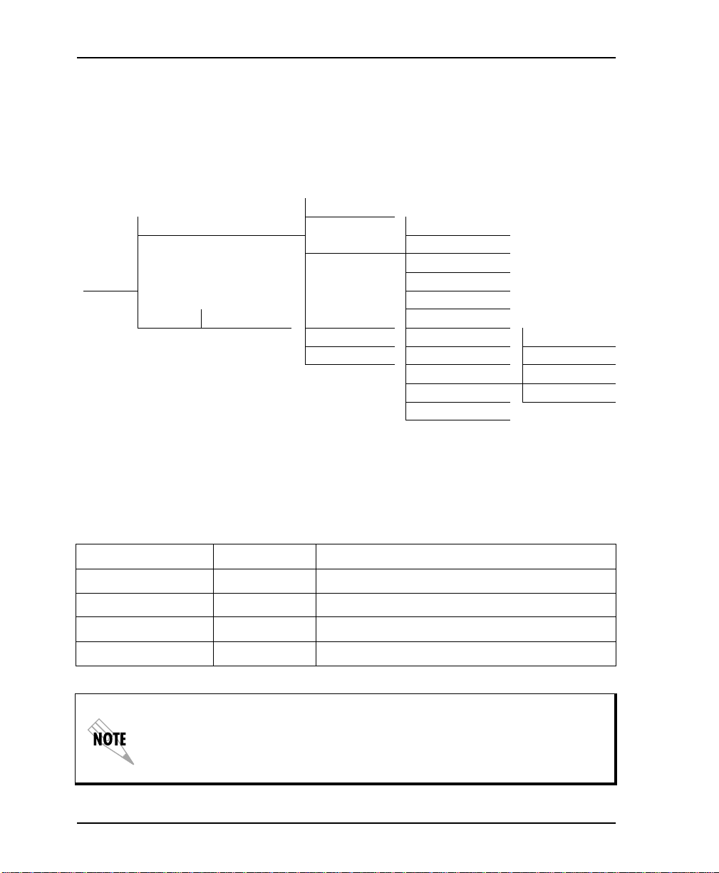
Chapter 6. Configuring DTE Options
TR Options
menu is used to select the DSU III AR response to
The TR O
the data terminal ready (TR) lead. The factory default setting is
I
GNORED
1= LOCAL 1= DTE RATE
3= CONFIG 4= DTE CMD OPTION
2= REMOTE ENTER ADDRESS 3= TEST OPTIONS 6= CS OPTIONS
PTIONS
(see Figure 6-10).
1= NETWORK OPT.
2= DTE OPTIONS 2= CONNECTOR TYPE
3= DATA FORMAT
5= TRANSMIT CLOCK
4= DIAL OPTIONS 7= ANTI-STREAM 1= IGNORED
5= MANUAL COM. 8= CD OPTIONS 2= IDLE WHEN OFF
9= TR OPTIONS 3= OFF> ON DIAL #1
A= SR OPTIONS 4= OFF> ON DIAL #2
B= AUXILIAR Y P ORT
Figure 6-10. Selecting TR Options
Table 6-9 shows the equivalent AT commands for setting
TR O
PTIONS
.
Table 6-9. TR Options AT C ommands
Front Panel AT Command Description
1=IGNORE &D0 Ignore the TR input.
2=IDLE WHEN OFF &D2 See the following note.
3=OFF>ON DIAL #1 &D3 Dial Stored #1: TR goes off to on (SW56 only).
4=OFF>ON DIAL #2 &D4 Dial Stored #2: TR goes off to on (SW56 only).
DLE WHEN OFF
For I
option: In SW56 mode, TR off will cause the DSU to go
On Hook (Idle). The unit also will not dial out if TR is off. In dedicated mode,
the DSU will go into DTE command mode when TR goes off. When TR goe s
on, if the DSU does not receive a command in the number of seconds set in S40,
the DSU will go into data mode.
6-14 DSU III AR User Manual 61202011L1-1
Page 69
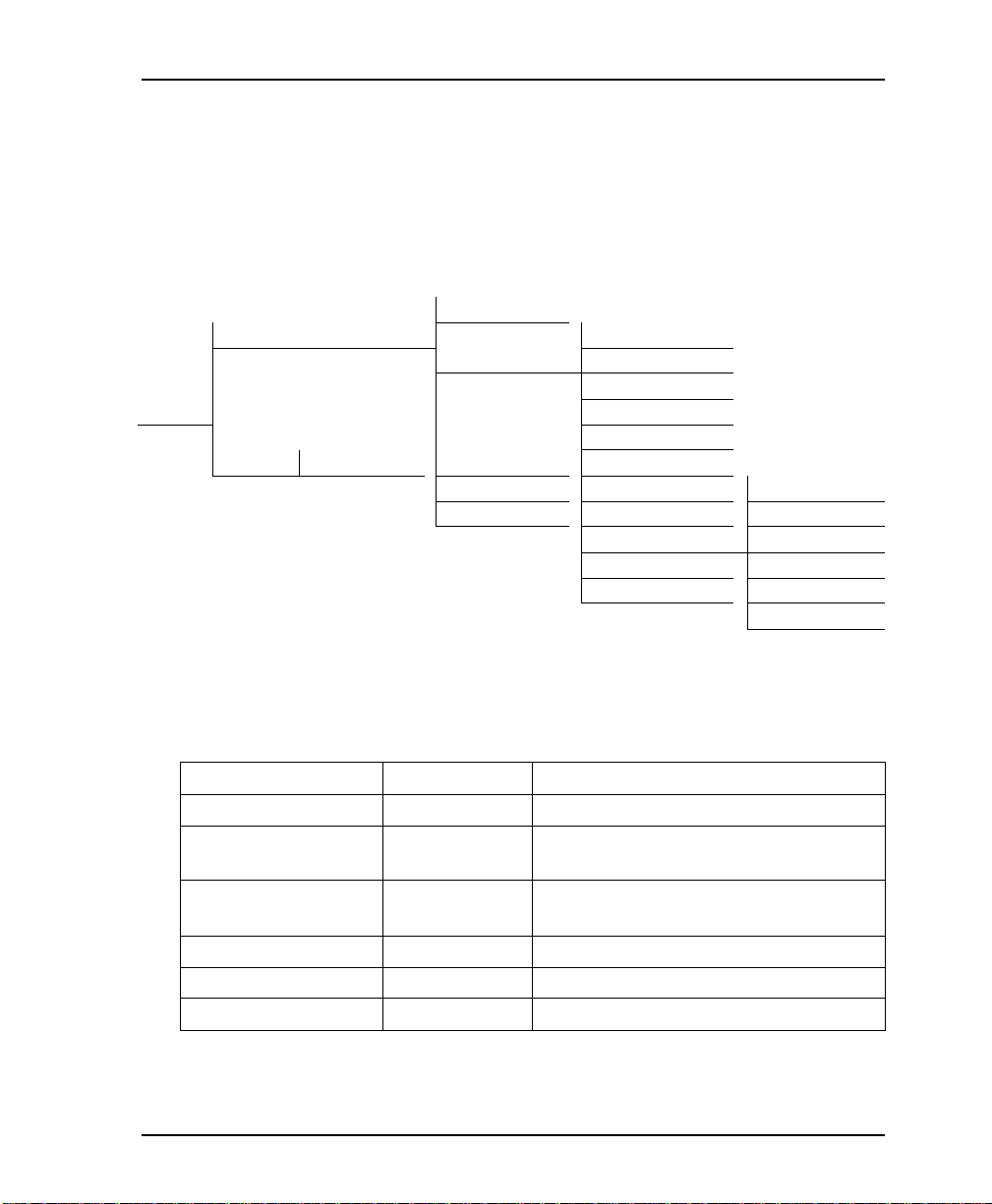
Chapter 6. Configuring DTE Options
SR Options
menu is used to select the operating mode for the
The SR O
data set ready (SR) lead. From the DTE options menu, press
A
to activate the SR O
The factory default setting is O
1= LOCAL 1= DTE RATE
3=CONFIG 4= DTE CMD OPTION
2= REMOTE ENTER ADDRES S 3= TEST OPTIONS 6= C S OPTIONS
PTIONS
PTIONS
submenu; then press E
FF TEST ONLY
1= NETWORK OPT.
2= DTE OPTIONS 2= CONNECTOR TYPE
3= DATA FORMAT
5= TRANSMIT CLOCK
4= DIAL OPTIONS 7= ANTI-STREAM 1= FORCED ON
5= MANUAL COM. 8= CD OPTIONS 2= OFF OOS ONLY
9= TR OPTIONS 3= OFF LOCD ONLY
A= SR OPTIONS 4= OFF TEST ONLY
B= AUXILIARY PORT 5 = OFF TEST +OOS
(see Figure 6-11).
Figure 6-11. Setting SR Op ti ons
Shift +
NTER
to selec t.
6= OFF TEST + LOCD
PTIONS
Table 6-10 shows the AT commands for setting SR O
.
Table 6-10. SR Options AT Commands
Front Panel AT Command Description
1=FORCED ON &S0 Alway s on
2=OFF OOS ONLY &S1 Off when network Out Of Service
(OOS)
3=OFF LOCD ONLY &S3 Off 5 seconds after disconnect (SW56
only)
4=OFF TEST ONLY &S0_C0 Off when unit is in test
5=OFF TEST +OOS &S1_C0 Off in test or OOS
6=OFF TEST +LOCD &S5 Off 5 seconds after disconnect or test
61202011L1-1 DSU III AR User Manual 6-15
Page 70

Chapter 6. Configuring DTE Options
Auxiliary Port
UXILIARY PORT
The A
option is used to select the operating speed for
the secondary channel if the secondary channel option was selected
during setup of the N
ETWORK OPTIONS
DTE options menu, press
submenu and press
UXILIARY PORT
The A
Enter
has an internal 256 byte buffer. If the
Shift + B
to select. The factory default is OFF.
(see Figure 6-12). From the
to activate the A
UXILIARY PORT
secondary channel speed is higher than the throughput in the
network, CTS flow control is activated. If the secondary DTE does
not respond to CTS flow control, care should be taken to prevent
the A
UXILIARY PORT
UXILIARY PORT
A
internal buffer from overflowing. The
option may also be used to provide VT-100 menu
access through the EIA-232 interface. For more details on this
option, refer to VT -1 00 Con nec tion on page 4-5.
1= NETWORK OPT.
1= LOCAL 1= DTE RATE
2= DTE OPTIONS 2= CONNECTOR TYPE
3= DATA FORM AT 1= 1.2K AT_CMD
3= CONFIG 4= DTE CMD OPTION 2= 75 SEC
5= TRANSMIT CLOCK 3= 150 SEC
2= REMOTE ENTER ADDRESS 3= TEST OPTIONS 6= CS OPTIONS 4= 300 SEC
4= DIAL OPTIONS 7= ANTI-STREAM 5= 600 SEC
5= MANUAL COM. 8= CD OPTIONS 6= 1.2K SEC
9=TR OPTIONS 7= 2.4K SEC
A= SR OPTIONS 8= OFF
B= AUXILIARY PORT 9= 300 CONTROL
A= 1.2K CONTROL
B= 2.4K CONTROL
C= 9.6K CONT ROL
Figure 6-12. Setting the Secondary Rate
6-16 DSU III AR User Manual 61202011L1-1
Page 71

Chapter 6. Configuring DTE Options
Table 6-11 shows the equivalent AT commands for setting the
secondary rate option. Network throughput is shown in Table 6-12.
Table 6-11. Aux iliary Port AT Commands
Front Panel AT Command Description
1=OFF _Y0 No secondary channel selected
2=75 _Y1 Secondary channel rate: 75 bps
3=150 _Y2 Secondary channel rate 150 bps
4=300 _Y3 Secondary channel rate: 300 bps
5=600 _Y4 Secondary channel rate 600 bps
6=1.2K _Y5 Secondary channel rate 1200 bps
7=2.4K _Y6 Secondary channel rate: 2400 bps
Table 6-12. DSU III AR Network Throughput
Loop Rate Secondary Channel Throughput
2.4k 78
4.8k 156
9.6k 312
19.2k 627
38.4k 1.25k
56k No Scrambler 1.83k
56k Scrambler 2.4k
61202011L1-1 DSU III AR User Manual 6-17
Page 72

Chapter 6. Configuring DTE Options
6-18 DSU III AR User Manual 61202011L1-1
Page 73

Chapter 7
Configuring Test Options
TEST OPTIONS
EST OPTIONS
The T
and specifies the maximum test time allowed.
menu enables or disables different test modes
Test Time-out
EST TIME-OUT
The T
remains in a test mode before automatically returning to the data
mode. Enter the time-out from 0 to 255 seconds. The factory default
setting is off (0). Figure 7-1 shows the menu path used to access
T
EST TIME-OUT
1= LOCAL 2= DTE OPTIONS
3=CONFIG 3= TEST OPTIONS 1= TEST TIMEOUT ENTER TIME-OUT
2= REMOTE ENTER ADDRESS 5= MANUAL 3= EIA LLB /EN /DIS
option sets the length of time a DSU III AR
.
1= NETWORK OPT.
4= DIAL OPTIONS 2 = RD L/E N /DIS (0=OFF: 00 SEC)
4= EIA RLB /EN /DIS
Figure 7-1. Setting Test Time-out Option
61202011L1-1 DSU III AR User Manual 7-1
Page 74

Chapter 7. Configuring Test Options
Table 7-1 shows the equivalent AT commands for setting the
EST TIME-OUT
T
.
Table 7-1. Test Timeout AT Commands
Front Panel AT Command Description
ENTER TIMEOUT S18=x Specify 0 - 255 seconds test time-out
Remote Digital Loopback
EMOTE DIGITAL LOOPBACK
The R
(RDL) option specifies whether the
DSU III AR responds to an RDL request from the far end of the
circuit. The factory default setting is RDL A
CCEPTED
. Figure 7-2
shows the menu path used to access this option.
1= NETWORK OPT.
1= LOCAL
3=CONFIG 2= DTS OPTIONS 1= TEST TIMEOUT 1= RDL IGNORED
3= TEST OPTIONS 2= RDL/EN /DIS 2= RDL ACCEPTED
2= REMOTE ENT ER ADDRESS 4= DIAL OPTIONS 3= EIA LLB /EN /DIS
5= MANUAL 4= EIA RLB /EN /DIS
Figure 7-2. Remote Digital Loopback
Table 7-2 shows the equivalent AT commands for setting the
RDL O
PTION
.
Table 7-2. Remote Digital Loopback AT Commands
Front Panel AT Command Description
1=RDL IGNORED &T5 RDL request from remote DS U ignor ed
2=RDL ACCEPTED &T4 RDL request accepted
7-2 DSU III AR User Manual 61202011L1-1
Page 75

Chapter 7. Configuring Test Options
EIA Local Loopback
The EIA LLB (Electronics Industries Association Local Loopback)
option specifies whether the DSU III AR responds to the LLB input
from the DTE. The factory default setting is D
shows the menu path used to access the EIA LLB option.
1= NETWORK OPT.
1= LOCAL
2= DTE OPTIONS 1= TEST TIMEOUT
2= RDL/EN /DIS
3=CONFIG 3= TEST OPTIONS 3= EIA LLB /EN /DIS 1= DISABLED
4= DIAL OPTIONS 4= EIA RLB /EN /DIS 2= ENABED
2= REMOTE ENTER ADDRESS 5= MANUAL
Figure 7-3. EIA Local Loopback Options
Table 7-3 shows the equivalent AT commands for setting the
EIA LLB options.
Table 7-3. EIA Local Loopback AT Commands
ISABLED
. Figure 7-3
Front Panel AT Command De scription
1=DISABLED _A0 EIA LLB disabled
2=ENABLED _A1 EIA LLB enabled
61202011L1-1 DSU III AR User Manual 7-3
Page 76

Chapter 7. Configuring Test Options
EIA Remote Loopback
The EIA RLB (Electronics Industries Association Remote
Loopback) option specifies whether the DSU III AR responds to the
RLB input from the DTE. The factory default setting is D
Figure 7-4 shows the menu path for the EIA RLB options.
1= NETWORK OPT.
1= LOCAL 1= TEST TIMEOUT
3=CONFIG 2= DTS OPTIONS 2= RDL/EN /DIS
3= EIA LLB /EN /DIS
2= REMOTE ENTER ADDRESS 3= TEST OPTIONS 4= EIA RLB /EN /DIS 1= DISABLED
4= DIAL OPTIONS 2= ENABED
5= MANUAL
Figure 7-4. EIA Remote Loopback Options
Table 7-4 shows the equivalent AT commands for setting the EIA
RLB options.
Table 7-4. EIA Remote Loopback AT Commands
ISABLED
.
Front Panel AT Command Description
1=DISABLED _R0 EIA RLB disabled
2=ENABLED _R1 E IA RLB enabled
7-4 DSU III AR User Manual 61202011L1-1
Page 77

Chapter 8
Configuring Dial Options
DIAL OPTIONS
IAL OPTIONS
The D
defines the A
configured for Switched 56 operation.
menu stores up to ten phone numbers and
UTO ANSWER
operation of the DSU III AR when it is
Phone Number
The DSU III AR stores up to 10 numbers of 36 digits each. Edit a
phone number by reentering the entire number. This process
overwrites the previously stored number. Figure 8-1 shows the
menu path used to acc ess the P
1=NETWORK
1=LOCAL 2= DTE OPTIONS
3=TEST OPTI ONS
3=CONFIG STORED NUMB ER
2=REMOTE ENTER 4=DIAL OPTIONS 1=PHONE TO EDIT: (1-10) NNNNNNN
ADDRESS 2=AUTO ANSWER
HONE NUMBER
option.
Figure 8-1. Editing Stored Phone Numbers
61202011L1-1 DSU III AR User Manual 8-1
Page 78

Chapter 8. Configuring Dial Options
Table 8-1 shows the AT Command for storing phone numbers.
Auto Answer
UTO ANSWER
The A
to be answered. If E
answered by the DSU III AR. If D
answered manually by an AT or V.25 command from the DTE, or
by raising TR from the DTE. Figure 8-2 shows the menu path used
to enable or disable this option.
1= LOCAL 2= DTE OPTIONS
3=CONFIG
2= REMOTE ENTER ADDRESS 4= DIAL OPTIONS 2= AUTO ANSWER
Table 8-1. AT Command for Storing Phone Numbers
AT Command Description
&Zn= Store Phone Number
option is used to specify how incoming calls are
NABLED
, incoming calls are automatically
ISABLED
1= NETWORK
3= TEST OPTIONS
, an incoming call can be
1= PHONE
1= DISABLED
2= ENABLED
Figure 8-2. Enabling/Disabling the Auto Answer Function
Table 8-2 shows the AT Commands available for the A
UTO ANSWER
option.
Table 8-2. AT Commands for Auto Answer
Front Panel AT Command Description
1=DISABLED _J0 Auto Answer disabled
2=ENABLED _J1 Auto Answer enabled
8-2 DSU III AR User Manual 61202011L1-1
Page 79

Chapter 9
Manual Command
MANUAL COMMAND
ANUAL COMMAND
The M
configuration and control commands for the DSU III AR.
The first display prompts the user to enter the command number.
COMMAND:00
Figure 9-1 shows the menu path for M
The available manual commands are listed in Table 9-1 on page 9-3.
1= LOCAL 2= DTE OPTIONS
3=CONFIG COMMAND: 00
2= REMOTE ENTER ADDRESS 5= MANUAL COMMAND COMMAND: 00 VALUE: 00
option is a shortcut method for entering
ANUAL COMMAND
1= NETWORK OPT.
3= TEST OPTIONS
4= DIAL OPTIONS
Figure 9-1. Menu Path fo r Manual Command
.
61202011L1-1 DSU III AR User Manual 9-1
Page 80

Chapter 9. Manual Command
Using the Front Panel to Enter a Manual Command
When using the front panel, perform the following steps to enter a
manual command.
Step Action Explanation
1 Use the nu mbe r key s t o en te r
the hexadecimal command
number.
Press
to complete.
Enter
2 The command value can be
edited or reissued with the existing value.
COMMAND: XX
VALUE: 00
3 Use the nu mbe r key s t o en te r
the hexadecimal value.
4 Press
to complete. The system briefly displa ys
Enter
When the command number is entered, the display sh o ws both the
command number and the present
value or setting for the command.
OMMAND ACCEPTED
C
and returns
to the active menu.
9-2 DSU III AR User Manual 61202011L1-1
Page 81

Chapter 9. Manual Command
Table 9-1. Manual Commands
Command Description Command Value
AT Command Echo
Disable 82 00
Enable 82 01
AT Result code
Enable 85 00
Disable 85 01
AT Long or Short code
Short form 86 00 to FF
Long form 86 00 to FF
AT Escape Character 2 00 to FF
AT CR Character 3 00 to FF
AT LF Character 4 00 to FF
AT BS Character 5 00 to FF
AT Escape Char. Timer 0C 00 to FF
Abort Call Timer 7 00 to FF
DTR Recognize Delay (x 2.5ms) 19 00 to FF
DTR Initiated Command Time-out (seconds) 28 00 to FF
Load Factory Opt.
Option Set #1 8A 00
Option Set #2 8A 01
Option Set #3 8A 02
Option Set #4 8A 03
Store User Profile
Save to Profile 0 91 00
Save to Profile 1 91 01
Select User Profile
Power Up Profile 0 93 00
Power Up Profile 1 93 01
Network Address Lock
Network Addr. Unlock C3 00
Network Addr. Lock C3 01
61202011L1-1 DSU III AR User Manual 9-3
Page 82

Chapter 9. Manual Command
9-4 DSU III AR User Manual 61202011L1-1
Page 83

Chapter 10
Dial Selection
DIAL OPTIONS
selection available in the M
IAL
The D
options for manual dialing, redialing, and dialing stored numbers.
The D
IAL
selection is available for use only if AT&T/MCI SW56 or
SW56 is the selected N
PRINT
US S
on page 5-5 in Chapter 5.
Figure 10-1 below shows the menu path used to access these
options.
1= DIAL STORED # Select Stor ed Number 1-A
4=DIAL 2= ENTER DIAL # NNNN NNN
3= REDAIL LAST #
menu (D
AIN
ETWORK TYPE
Figure 10-1. Dial Options Menu
IAL
) includes
. See Network Type
61202011L1-1 DSU III AR User Manual 10-1
Page 84

Chapter 10. Dial Selection
Dial Stored Number
This option allows a stored number to be dialed. The numbers are
stored within the C
ONFIG
selection.
Figure 10- 2 below shows the C
ONFIG
menu path used to access the
dial options and store phone numbers.
See Chapter 8 Configuring Dial Options on page 8-1 for more
information.
1= NETWORK TYPE
1= LOCAL 2= DTE OPTIONS
3= TEST OPTIONS
STORED NUMBER
3= CONFIG 4= DIAL OPTIONS 1= PHONE N O. EDIT: (1-10) NNNNNNN
2= REMOTE ENTER 2= AUTO ANSWER
ADDRESS 5= MANUAL
Figure 10-2. Path to Storing Numbers Option
Enter Dial Number
This option allows you to enter a phone number of up to 36 digits
for the DSU III AR to dial.
Redial Last Number
Selecting this option redials the last phone number entered.
10-2 DSU III AR User Manual 61202011L1-1
Page 85
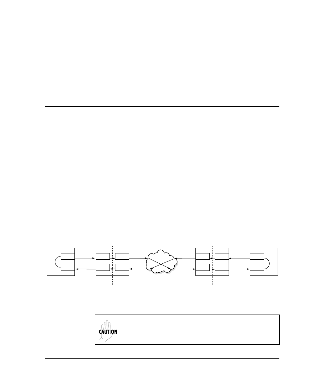
Chapter 11
Testing and Troubleshooting
TEST OVERVIEW
The DSU III AR performs a variety of diagnostic functions that
isolate portions of the circuit to identify the problem source. Tests
may be initiated and terminated from the front panel or the DTE
interface. In asynchronous mode, AT commands can control the
testing from the DTE interface. For synchronous operation, V .25 bis
commands can provide test control.
The unit also responds to standard DDS network tests initiated
from telco test centers. In addition, it can run several tests such as
local and remote loopbacks to aid in problem isolation. See Figure
11-1.
DTE DTE
TD
RD
LOCAL
DSU/CSU
Tx
Rx
Tx
Rx
TELCO
REMOTE
DSU/CSU
Tx
Rx
Tx
Rx
TD
RD
Figure 11-1. Normal Operation Before Initiating Loopback Test
All diagnostic tests disrupt data flow.
61202011L1-1 DSU III AR User Manual 11-1
Page 86

Chapter 11. Testing and Troubleshooting
Initiating a Test
To initiate tests, perform the following steps:
Step Action
To se lect T
1
Enter
Specify L
2
corresponding number; then press
EST
from the main menu, press 2; then press
.
OCAL
, R
EMOTE
, or AR testing by selecting the
.
Enter
3 Use the up and down arrows to view test options.
Select a test from the available options by pressing the
4
corresponding number and then
Enter
.
The example in Figure 11-2 shows the menu path for initiating a
local DTE and Loop test.
1=DTE & LOOP (LL)
2=LOOP ONLY (RT)
1=LOCAL UNIT 3=DTE ONLY
4=DTE WITH TP
5=TEST PATTERN
2=TEST 6=SELF TEST
2=REMOTE UNIT ENTER TEST UNIT
ADDRESS: 0
Figure 11-2. Initiating a Test
Once a test is initiated P
LEASE WAIT
displays briefly and is
followed by the status screen.
11-2 DSU III AR User Manual 61202011L1-1
Page 87

Test Status Display
EST STATUS
The T
EST STATUS
T
Chapter 12, V iewing Status Information on page 12-1 with add itional
prompts for the type of test and the number of errors (for tests with
a test pattern).
Chapter 11. Testing and Troubleshooting
display appears automatically during a test. The
display is similar to the status screen described in
Figure 11-3 shows an example of a T
test with a test pattern. Figure 11-4 on page 11-4 shows the
complete test menu.
DTE WITH TEST PATTERN
TST ERR = 00
LOOP 56K
DTE 56K SYNC
TR SR LLB RLB
OFF OFF OFF OFF
UNIT IN TEST
LOOP IS NORMAL
Exiting a Test
During a test, press the
S
T
are available only after a test has been initiated:
TATUS
menu or press
EST/DISPLAY STATUS
EST STATUS DISPLAY
While this menu is on the display:
1
to clear errors.
Press
Press
2
to inject an error.
Use the up and down arrows to
display other status screens.
for a DTE
Figure 11-3. Sample Test Status Displays
key to access the E
Quick
Cancel
to return to the Main menu. The E
XIT TEST/DISPLAY
XIT
menu provides the following options, which
Exit Test Exits the current test and returns to the Main
menu.
Display Status Reenters test display.
61202011L1-1 DSU III AR User Manual 11-3
Page 88

Chapter 11. Testing and Troubleshooting
1=DTE & LOOP (LL) STATUS DISPLAY 1=EXIT TEST
2=DISPLAY STATUS
2=LOOP ONLY (RT) STATUS DISPLAY 1=EXIT TEST
2=DISPLAY STATUS
3=DTE ONLY STATUS DISPLAY 1=EXIT TEST
1=LOCAL UNIT 2=DISPLAY STATUS
1=2047 PATTERN
4=DTE WITH TP 2=511 PATTERN 1=EXIT TEST
TEST 3=STRESS PTRN #1 STATUS DISPLAY 2=DISPLAY STATUS
4=STRESS PTRN #2
5=STRESS PTRN #3
6=STRESS PTRN #4
1=2047 PATTERN
2=511 PATTERN
3=STRESS PTRN #1 1=EXIT TEST
5=TEST PATTERN 4=STRESS PTRN #2 STATUS DISPLAY 2=DISPLAY STATUS
5=STRESS PTRN #3
6=STRESS PTRN #4
6=SELF TEST ST ATUS DISPLAY
1=2047 PATTERN 1=EXIT TEST
2=511 PATTERN STATUS DISPLAY 2=DISPLAY STATUS
2=REMOTE UNIT ENTER TEST UNIT 3=STRESS PTRN #1
ADDRESS: 0 4=STRESS PTRN #2
5=STRESS PTRN #3
6=STRESS PTRN #4
7=DATA FROM DTE
Figure 11-4. Complete Test Menu
When the
STATUS DISPLAY
is active, press the
key to access the E
Quick
XIT TEST
menus.
11-4 DSU III AR User Manual 61202011L1-1
Page 89
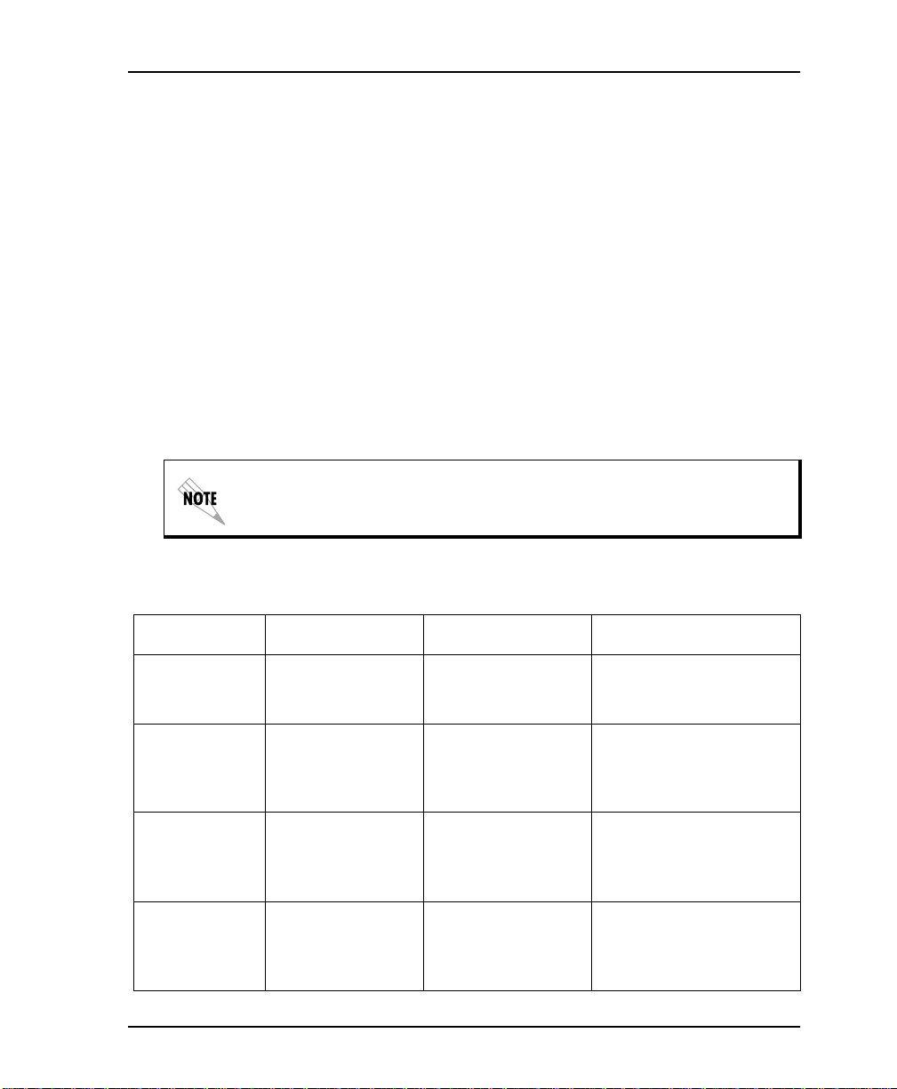
TROUBLESHOOTING
This section is intended to provide a quick and easy means of
diagnosing suspected problems associated with local or remotely
attached ADTRAN DSU/CSUs. Two separate troubleshooting
sections are provided; one focuses on new installs, the other on
existing circuits.
Messages from the DSU/CSU
The DSU III AR displays messages on the LCD display and LEDs
concerning the status of the unit and the local loop. If the Alarm
LED is O
displayed on the LCD.
N
, at least one of the messages shown in Table 11-1 will be
Chapter 11. Testing and Troubleshooting
S
The
messages. Press the
menu must be selected in order for the unit to display status
TATUS
Quick
key to return to the main men u, where S
can be selected.
Table 11-1. Messages from the DSU/CSU
Message Meaning Probable Cause Action
LOOP IS
NORMAL
OPEN LOOP
NO RX
SIGNAL
OOS/OOF
FROM NET
Good local loop signal being received
from the telco.
Unit not receiving a
signal from the telco.
Unit detects sealing
current but no data
signal from telco.
Unit detects an Out of
Service or Out of
Frame condition from
the telco.
Indicates good local
loop.
Bad telco cable from
the DSU to telco jack
or bad circuit to telco.
Bad conductor in telco
cable from DSU to telco jack or bad circuit to
telco.
Telco is having problems with DDS circuit
or remote unit is turned
off or disconnected.
No action required; unit
properly connected to telco
circuit.
Replace telco cable from
DSU to wall jack. If a problem persists, contact telco
provider.
Replace telco cable from
DSU to wall jack. If a problem persists, contact telco
provider.
Check remote unit. Contact
telco service provider. If a
problem persists, conta ct telco provider.
TATUS
61202011L1-1 DSU III AR User Manual 11-5
Page 90

Chapter 11. Testing and Troubleshooting
Table 11-1. Messages from the DSU/CSU (Continued)
Message Meaning Probable Cause Action
CHECK
TELCO LINE
TEST FROM
TELCO
Transmit/receive pair
reversal detected.
Telco activated a
loopback to test the
DDS circuit.
Telco wall jack wired
incorrectly.
Telco is testing circuit. Wait until test is complete or
Troubleshooting New Installs
Before initiating diagnostics on a newly installed unit and/or DDS
circuit and before contacting ADTRAN Technical Support, please
check the items in Table 11-2 to ensure the unit is configured
properly.
After verifying the items listed in Table 11-2 on page 11-7, the unit
should operate properly and display the following:
DATA MODE
LOOP IS NORMAL
If a status message other than D
shown, begin performing diagnostics described in the section Test
Sequence for Troubleshooting New Installs or Existing Circuits on page
11-8.
Switch wire pairs in wall jack
or contact telco se rvice provider.
contact telco service provider.
ATA MODE LOOP IS NORMAL
is
11-6 DSU III AR User Manual 61202011L1-1
Page 91

Chapter 11. Testing and Troubleshooting
Table 11-2. Troubleshooting New Installs
Configuration Item to
Check
Option Selection Action
DTE Type EIA-232 or V.35 Select the type of DTE interface
option to connect to the DSU/
CSU from the configuration
menu.
Loop Rate Auto, 2.4 to 64 kbps Select the DDS loop rate of the
DDS circuit from the configuration
menu.
Data Format Async or Sync Select the type of data to be used
from the configuration menu.
DTE Cable N/A Verify DTE cable connection to
the proper DTE connector on the
DSU/CSU.
Telco Cable N/A Verify the telco ca ble is secure ly
connected to the DSU/CSU and
wall jack.
Power the unit Off and
then On.
N/A Verify the unit passes self test
during power-up (displayed on
the LCD).
61202011L1-1 DSU III AR User Manual 11-7
Page 92
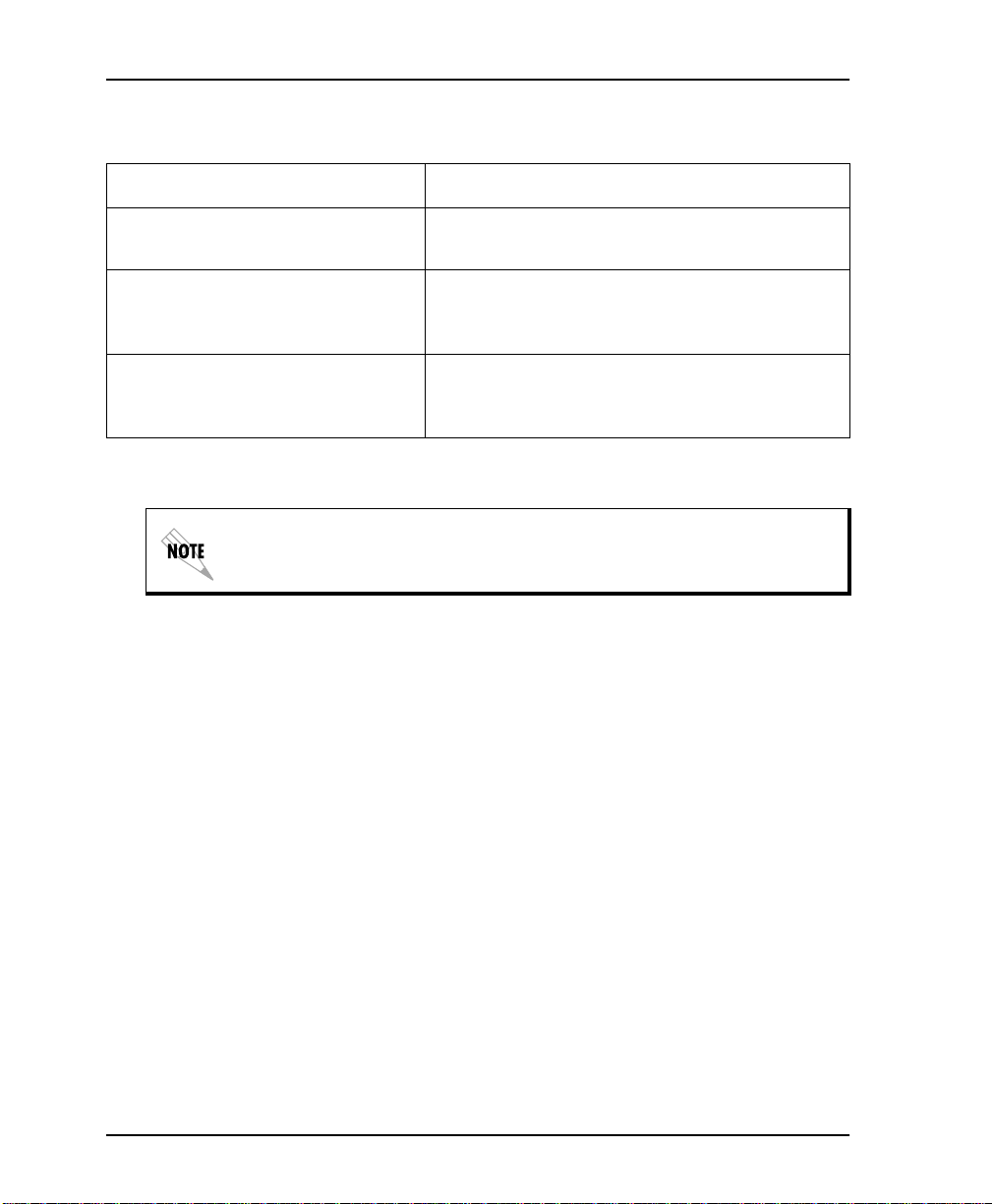
Chapter 11. Testing and Troubleshooting
Test Sequence for Troubleshooting New Installs or Existing Circuits
If your DSU... Do this...
seems to be having problems Perform a Self Test to determine if the unit is
operational
is receiving excess i ve data er ror s Perform a DTE with Test Pattern requiring re-
transmission to determine if the unit's internal
transmitter and receiver is operating error free
is receiving excess ive errors
requiring retransmission of data
and the remote unit is error free
If an external BERT tester is available, these additional tests may be performed: DTE & Loop Test, DTE Only Test, and Loop Only Test.
If the unit fails any of these tests or the problem has not been
determined, contact ADTRAN Technical Support (see page xi in
the front section of this manual).
The DSU III AR unit diagnostics tests can be initiated through AT
Commands from the DTE interface. These commands are listed in
Table 11-3 on page 11-9.
Perform a Remote Test to verify the connection
between the local and remote unit is error free.
Run the test using all available test patterns
11-8 DSU III AR User Manual 61202011L1-1
Page 93

Chapter 11. Testing and Troubleshooting
Table 11-3. AT Commands
Command Title Default
A/ Re-execute Command none
ATA Answer none
ATDn Dial Number none
ATE Echo Command 1
ATH Hang Up Call none
ATO Go Online none
ATQn Result Code Display 0
ATSn? Read S-Register none
ATSn=x Write to S-Register none
ATVn Result Code From 1
ATZ Reset none
AT&Cn DCD Option 0
AT&Dn DTR Option 0
AT&Fn Restore Factor y Op tio ns none
AT&Kn Flow Control none
AT&Ln N et work Type 0
AT&Qn DTE Data Format 0
AT&Rn CS Options 0
AT&Sn SR Options 0
AT&Tn Test Commands 0
AT&V View Current Configuratio n none
AT&Wn Store User Profile 0
61202011L1-1 DSU III AR User Manual 11-9
Page 94

Chapter 11. Testing and Troubleshooting
LOCAL UNIT DIAGNOSTICS
The local DSU III AR can perform six differ ent tests. These tests can
be initiated through AT Commands from the DTE Interface. See
Table 11-4 for a list of the AT Commands.
Front Panel Display AT Command Description
DTE & Loop (LL) &T10 TD/RD and RX/TX Loopbacks
Loop Only (RT) &T11 RX/TX Loopback at Network Interface
DTE Only &T1 TX/RX Loopback at DTE Interface
DTE with TP &T8 RX/RX L oopb ac k with T es t Patter n
Test Pattern & T 9 Transmit/Receive Test Patter n
Self Test Z Check Internal Components ( R es ets
Exit Test &T0 Stops test, returns to data mode
TD = Customer Transmit Data
RD = Customer Receive Data
TX = Netwo r k Transmit Data
RX = Network Receive Data
T able 11-4. Tes t AT Comma nds
Unit)
The test patterns shown in T able 11-5 on page 11-11 are available for
the DTE with Test Pattern and Test Pattern tests.
11-10 DSU III AR User Manual 61202011L1-1
Page 95

Chapter 11. Testing and Troubleshooting
Table 11-5. DTE With Test Pattern Commands
Front Panel
AT
Command
Description
1=2047 PATTERN _T0&T8 Standard 2047 random data pattern.
2=511 PATTERN _T1&T8 Standard 511 rand om data pattern.
3=STRESS PTRN #1 _T2&T8 Stress pat tern with alt ernati ng hig h and
low ones densities. Repeated pattern of
100 octets: 1111 1111; followed by 100
octets: 0000 0000.
4=STRESS PTRN #2 _T3&T8 Stress pat tern with alt ernati ng med ium
and low ones densities. Repeated pattern
of 100 octets: 0111 1110; followed by 100
octets: 0000 0000.
5=STRESS PTRN #3 _T4&T8 Stress pattern with medium ones density.
Continuous series of octets: 0011 0010.
6=STRESS PTRN #4 _T5&T8 Stress pattern with low ones density. Con-
tinuous series of octets: 010 0 0000.
61202011L1-1 DSU III AR User Manual 11-11
Page 96
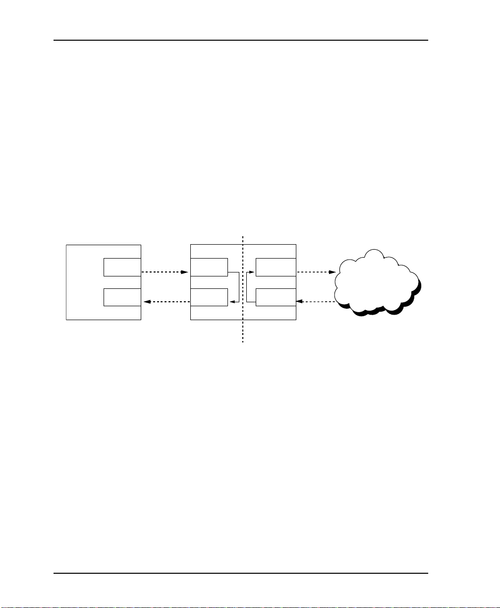
Chapter 11. Testing and Troubleshooting
DTE and Loop (LL)
Test Description
DTE
Test Purpose
The DTE & L
OOP
test splits the DSU III AR into two separate DTE
and loop interface sections and then loops the receive data of each
interface back to its respective transmit data. The DTE & L
provides a bidirectional loopback at the DSU/CSU.
Figure 11-5 illustrates the loopback points and the signal paths for
this test.
LOCAL
DSU/CSU
Tx
DTE Tx
NET Tx
TELCO
Rx
DTE Rx
NET Rx
Figure 11-5. DTE & Loop Test
OOP
test
The DTE & Loop test is used for the following purposes:
• Verify integrity of the DTE interface and cable.
• Provide a loopback for network tests.
11-12 DSU III AR User Manual 61202011L1-1
Page 97

Initiating
Follow the menu path outlined in Figure 11-6 to initiate a DTE &
OOP TEST
L
2=TEST 6=SELF TEST
Interpreting Test Results
A BERT tester must be used to interpret the test results of a DTE &
Loop test because the BERT originates external to the local DSU.
Chapter 11. Testing and Troubleshooting
.
1=DTE & LOOP (LL)
2=LOOP ONLY (RT)
3=DTE ONLY
1=LOCAL UNIT 4=DTE WITH TP
5=TEST PATTERN
2=REMOTE UNIT
Figure 11-6. Initiating a DTE & Loop Test
61202011L1-1 DSU III AR User Manual 11-13
Page 98

Chapter 11. Testing and Troubleshooting
Loop Only (RT)
OOP ONLY
The L
portion of the DTE interface for the local DSU III AR to be tested
from the remote site over the actual communication circuit.
Figure 11-7 illustrates the loopback point and the signal paths for
this test.
(RT) test allows the loop interface and a major
LOCAL
DSU/CSU
Test Purpose
DTE
Interface
The L
DTE Tx
DTE Rx
OOP ONLY
NET Tx
TELCO
NET Rx
Figure 1 1-7. Loop Only Test
test is used to provide a loopback for network tests.
11-14 DSU III AR User Manual 61202011L1-1
Page 99

Initiating
Follow the menu path outlined in Figure 11-8 to initiate a
OOP ONLY
L
2=TEST 6=SELF TEST
Interpreting Test Results
OOP ONLY
The L
telco. No test results are available from the local DSU III AR.
Chapter 11. Testing and Troubleshooting
test.
1=DTE & LOOP (LL)
2=LOOP ONLY (RT)
3=DTE ONLY
1=LOCAL UNIT 4=DTE WITH TP
5=TEST PATTERN
2=REMOTE UNIT
Figure 11-8. Initiating a Loop Only Tes t
test is used for looping the DDS circuit back to the
61202011L1-1 DSU III AR User Manual 11-15
Page 100
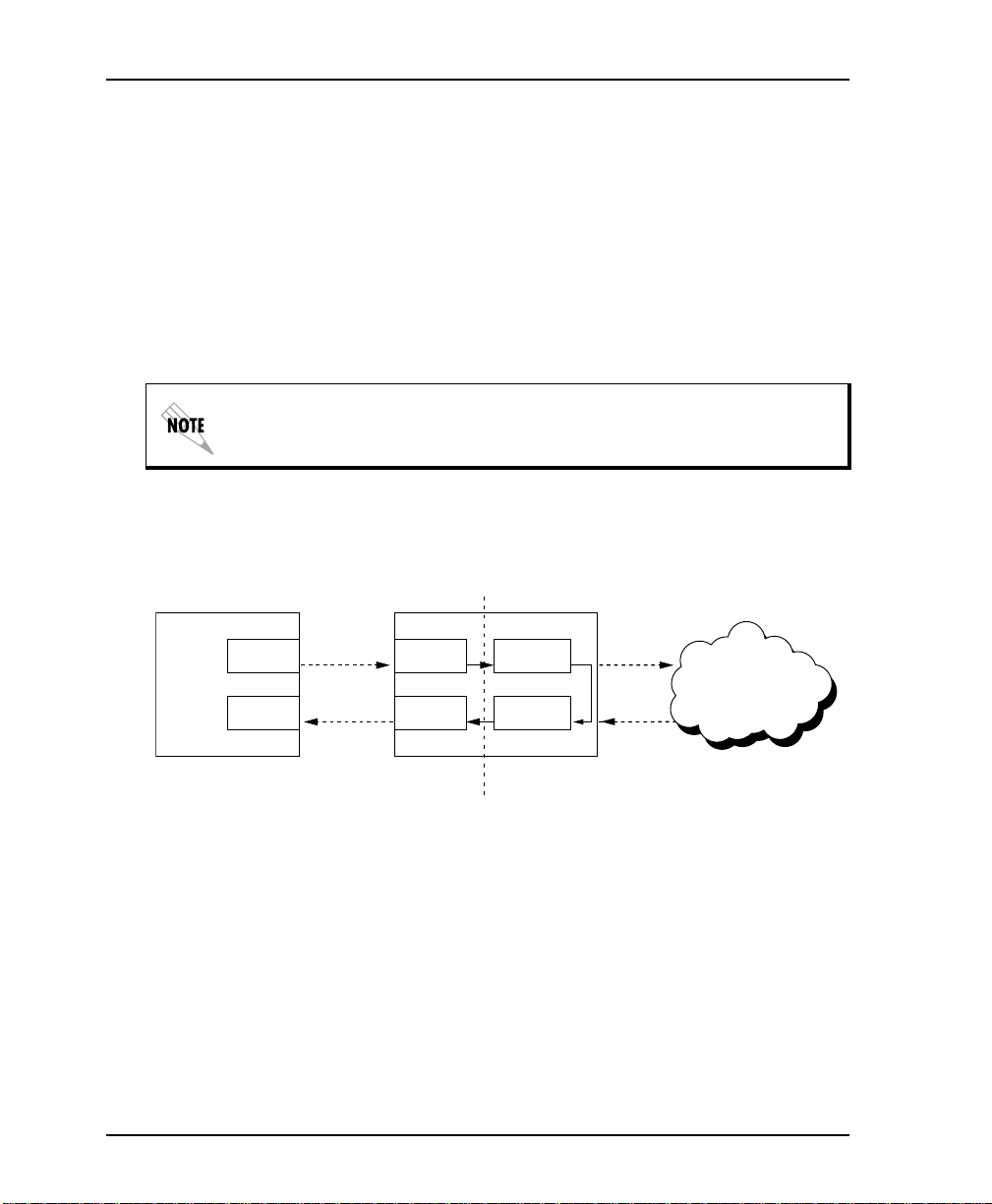
Chapter 11. Testing and Troubleshooting
DTE Only
The DTE O
NLY
test provides a method for testing both the DTE
interface drivers and receivers of the local DSU III AR plus its loop
transmitter and receiver. For this test, the loop transmit data is
connected to the loop receive data at a point close to the physical
network interface. This test can be used to verify proper operation
between the local DTE and the local DSU III AR. See Figure 11-9.
When this test is implemented, the far unit receives an
OOS/OOF
sage from the network and enters an alarm state.
LOCAL
DTE
TD
DSU/CSU
DTE Tx
NET Tx
TELCO
RD
DTE Rx
NET Rx
mes-
Figure 11-9. DTE Only Test Diagram
Test Purpose
The DTE O
NLY
test is used for the following purposes:
• To verify the integrity of the DTE interface.
• To verify the integrity of connection between DTE and
DSU III AR.
11-16 DSU III AR User Manual 61202011L1-1
 Loading...