

Page 1
Series 5 T otal Reach DDS-DP
Total Reach All-Rate DDS Dataport
Installation and Maintenance
CONTENTS
1. GENERAL ...................................................................... 1
2. INSTALLATION ........................................................... 3
3. TESTING ........................................................................ 3
4. REMOTE PROVISIONING AND DIAGNOSTICS ..... 5
5. DEPLOYMENT GUIDELINES .................................... 6
6. MAINTENANCE ........................................................... 7
7. WARRANTY AND CUSTOMER SERVICE ............... 8
Figures
Figure 1. Series 5 Total Reach DDS-DP ........................... 1
Figure 2. Total Reach DDS Circuit Diagram .................... 2
Figure 3. Option Switch ..................................................... 2
Figure 4. DS0 Bidirectional Loopback .............................. 4
Figure 5. DDS Trouble Codes ........................................... 5
Figure 6. Remote End Initiated Loopback, Local Loop .... 6
Figure 7. Remote End Initiated Loopback, Customer
Loop .................................................................... 6
Tables
Table 1. Option Settings..................................................... 2
Table 2. LED Indication..................................................... 4
Table 3. Latching Loopback Activation Sequence ............ 5
Table 4. Alternating Loopback Activation Sequence ........ 5
Table 5. Cable Type and Temperature Loss Data @
13.3 kHz ............................................................... 7
Table 6. Total Reach DDS Insertion Loss
Measurements ...................................................... 7
Table 7. Compliance codes ................................................ 7
1. GENERAL
This practice provides installation and maintenance
procedures for the ADTRAN Series 5 Total Reach
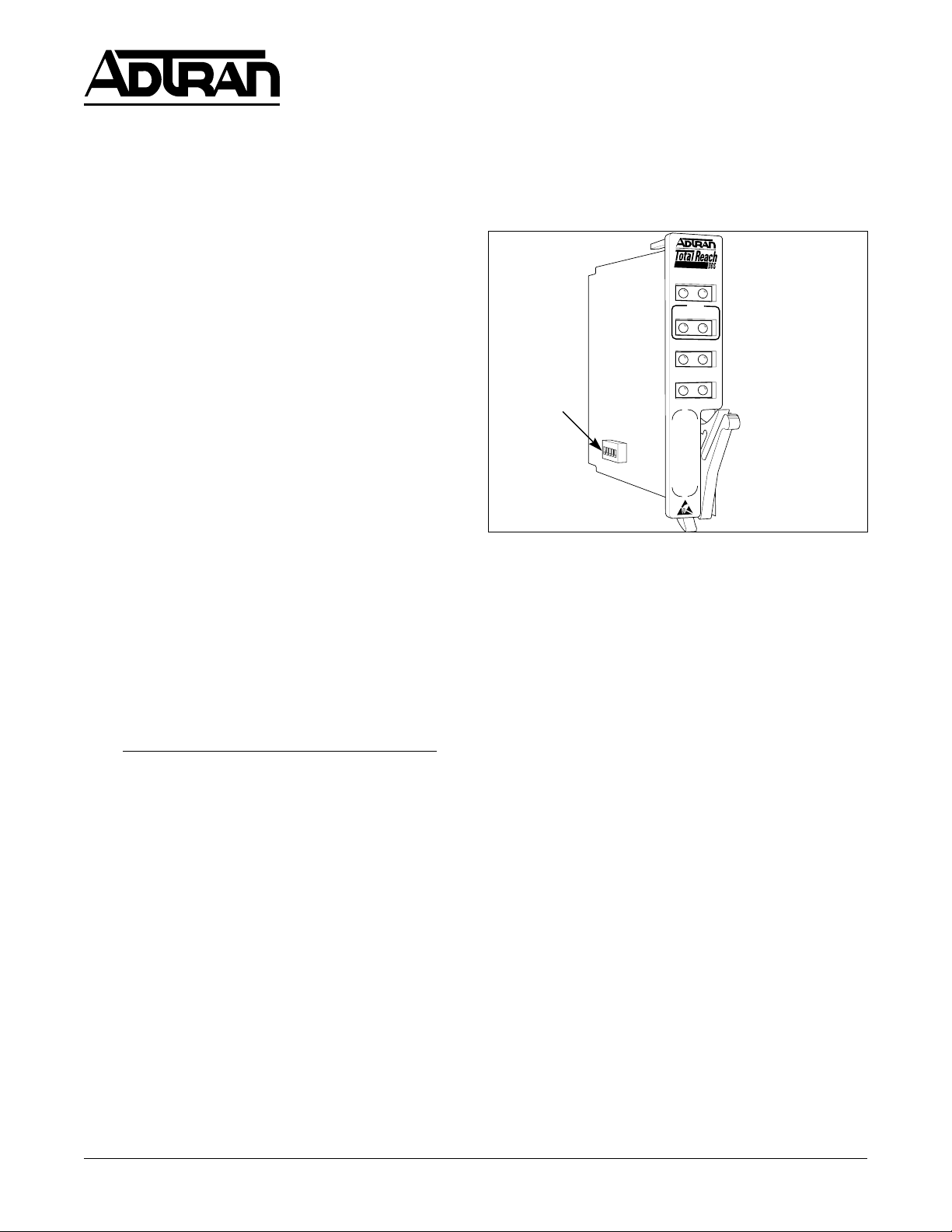
DDS-DP All-Rate DDS Dataport. Figure 1 is an
illustration of the ADTRAN Series 5 Total Reach
DDS-DP (P/N 1433105L5).
Revision History
This is the initial release of this document. Future
revisions will be described in this subsection.
Features
• 2-wire deployment
• Repeaterless operation
• Bridged tap tolerant
• Span power for remote Total Reach DDS-R
termination unit
• Utilization in SLC Series 5 and Series 2000 channel
banks
®
Section 61433105L2-5D
Issue 4, June 2000
CLEI Code # 5SC531PF_ _
DDS-DP
1433105
SX
SYN
C
CRC
FE
NE
D
SU
Q
M
LBK
MAN
SW2
Figure 1. Series 5 Total Reach DDS-DP
• Loop Quality Monitor and A/B signaling options
• Bidirectional DS0 loopback capability
• Transmits Mux Out of Sync code upstream during
out of service loop condition.
• Embedded Digital System 6 capabilities for remote
provisioning, and performance monitoring.
Description
The ADTRAN Series 5 Total Reach DDS-DP is a
functional replacement for the SLC
®
Series 5 OCU DP,
CLEI 5SCU48, delivering data at rates up to 64 kbps
using a single copper pair. Used in combination with the
Total Reach DDS-R termination unit, the Series 5 Total
Reach DDS-DP can accommodate extended loop
lengths, eliminating the need for DDS repeaters. The
Series 5 Total Reach DDS-DP span powers the Total
Reach DDS-R located at the customer premises. The
Total Reach DDS-R converts the 2-wire signal to the
traditional 4-wire Alternate Mark Inversion (AMI) signal
for presentation to the customer.
The ADTRAN Series 5 Total Reach DDS-DP
®
occupies a single channel position in the AT&T
SLC
Series 5 and Series 2000 or Series 5 compatible
channel bank. It provides the interface between a DS0
timeslot of the T-carrier data stream and the 2-wire
metallic loop extending to the customer premises. The
Trademarks: Any brand names and product names included in this document are trademarks,
registered trademarks, or trade names of their respective holders.
161433105L2-5D Section 61433105L2, Issue 4
Page 2
Series 5 Total Reach DDS-DP may interoperate over
UCB5seireSaivgninoisivorPerawtfoS
noitcnuFnoitpircseD
etaRspbk65ro,6.9,8.4,4.2tceleS
noitcerroCrorrE
)CE(
:tceles,2.91hguorht4.2sietarfI
elbaliavatonCECS(ENONroCEVM
).dracsihtnosetaresehtta
:tceles,spbk46hguorht65sietarfI
taA/NsiCEVM(ENONroCECS
).setareseht
)CZ(edoCoreZoNroseY
yradnoceS
)CS(lennahC
oNroseY
2WShctiwSpiDaivgninoisivorPerawdraH
K46)K46(1-2WS
lennahCraelCspbk46stcelesNO
K2.91
1
)K2.91(2-2WS
etarpool2.91stcelesNO
65dehctiwS)65WS(3-2WS
65dehctiwSselbaneNO
65dehctiwSselbasidFFO
gnilangiSB/A)GISBA(4-2WS
ehtfoetatsehtsenimretedtinuehtNO
slangisgnisustibgnilangisBdnaA
.enalpkcabknablennahcehtnotneserp
morfgnilangisseviredtinuehtFFO
.maertsatadgnimmocnieht
rotinoMytilauQ)MQ(5-2WS
MQselbaneNO
MQselbasidFFO
1
dna2WSno2.91tcelesnoitcerroCrorrEspbk2.91roF
.UIC5seireSCLShtiwCEVM6.9elbane
the carrier system with another Total Reach DDS-DP,
OCU DP, DS0 DP, 1/0 DCS, or switch and may be
located in an end office, hub office, intermediate
office, or Digital Loop Carrier (Figure 2). The
2-wire loop is connected using the odd pair Tip (pin
31) and Ring (pin 32) on the Series 5 backplane.
SLC
T-Carrier
SERIES 5
DLC
TR
DDS-DP
2-Wire Loop
T/R Pair
Customer Premises
4-Wire Customer
Interface
TR
DDS-R
DSU/CSU
Figure 2. Total Reach DDS Circuit Diagram
NOTE
The Series 5 Total Reach DDS-DP must be
used with an appropriate Total Reach DDSR unit.
Table 1. Option Settings
Options
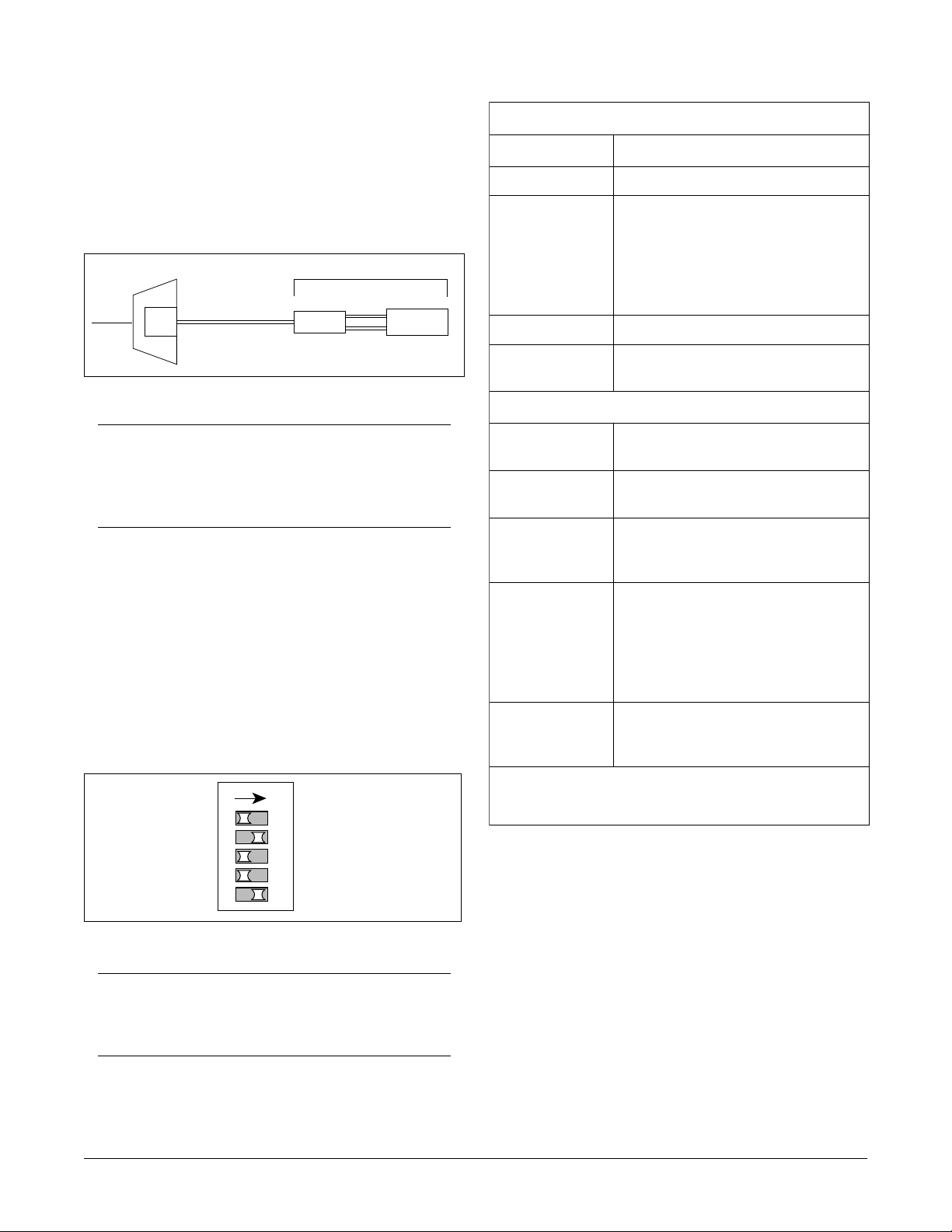
The Series 5 Total Reach DDS-DP is provisioned
through the SLC Series 5 system and an on-board DIP
switch. SW2 provides feature options not available
through the SLC Series 5 channel bank intelligent
system. Use the SLC Series 5 Craft Interface Unit (CIU)
to provision intelligent channel bank features supported
by the Series 5 Total Reach DDS-DP. See Figure 3
and Table 1 for option description and provisioning.
Error Correction
When error correction is enabled the Series 5 Total Reach
DDS-DP provides an error detection and correction
2 61433105L2-5DSection 61433105L2, Issue 4
ON
1
2345
SW2
64K
19.2K
SW56
ABSIG
QM
Figure 3. Option Switch
NOTE
Select OCU DP, CLEI 5SCU48, when
provisioning via the CIU.
capability that maintains data integrity across the carrier
facility. For subrate and 19.2 kbps rates, error correction
and data transmission is accomplished over a single DS0
time slot using a Majority Vote Error Correction
(MVEC) algorithm. For error correction at these rates,
MVEC must be selected in the BCU via the SLC Series 5
CIU.
For rates of 56 and 64 kbps, error correction requires one
additional DS0 time slot for the error correcting parity
byte. The Series 5 Total Reach DDS-DP only allows
SCEC, the parity byte error correction scheme, at 56 and
64 kbps. When error correction is desired for 19.2 kbps
service, provision 9.6 kbps and MVEC via the CIU and
select 19.2 on SW2.
Page 3

Zero Code
C A U T I O N !
SUBJECT TO ELECTROSTATIC DAMAGE
OR DECREASE IN RELIABILITY.
HANDLING PRECAUTIONS REQUIRED.
When Zero Code is enabled, the Series 5 Total Reach
DDS-DP allows DS0 bytes of all zeros to enter the
T-carrier data stream. On Alternate Mark Inversion
(AMI) facilities, this function should be disabled. B8ZS
carrier facilities that accommodate 64 kbps clear channel
operation do not require the zero code to be suppressed,
therefore zero code is automatically enabled when the 64
kbps rate has been selected.
Rate Selections
When 64K (SW2-1) is ON, the Series 5 Total Reach
DDS-DP operates at 64K Clear Channel.
When 19.2K (SW2-2) is ON, the Series 5 Total Reach
DDS-DP operates at 19.2 kbps.
Quality Monitor
When QM (SW2-5) is ON, the TR DDS-DP monitors
the 2-wire loop and 4-wire customer interface for data
errors. Excessive errors on the 2-wire loop cause the
unit to send an alternating ASC (9Eh)/MOS (9Ah) to
the network. Excessive errors on the 4-wire customer
interface cause the unit to send an ASC to the
network. In both cases customer transmission is
blocked. When the trouble condition clears
transmission is automatically restored.
2. INSTALLATION
When SW56 (SW2-3) is ON, the Series 5 Total Reach
DDS-DP enables Switched-56 operation.
NOTE
Only one rate should be selected. Service rates
of 64 kbps, 19.2 kbps, and Switched-56 are not
supported by the SLC Series 5 BCU. These
operating modes must be provisioned by
enabling switches on SW2. A manual rate
setting overrides BCU rate settings. The Series
5 Total Reach DDS-DP does not support 38.4
kbps.
The Total Reach DDS-DP can also be used in the SLC2000 channel bank but the card must still be provisioned
similar to the SLC-5 options. That is, 64 kbps operation
the card is switch selected for 64 kbps while the assigned
slot is selected for 56 kbps. For 19.2 kbps operation the
card is switch selected for 19.2 kbps while the assigned
slot is set for 9.6 kbps.
After unpacking the unit, inspect it for damage. If
damage is noted, file a claim with the carrier, then
contact ADTRAN. See Warranty and Customer
Service.
Tip/Ring Pair
The ADTRAN Series 5 Total Reach DDS-DP plugs
directly into a SLC Series 5 channel bank. No special
wiring is required. The 2-wire loop uses the T/R (Tip
and Ring) of the odd pair, pins 31 and 32 of the SLC
Series 5 backplane. The Total Reach DDS-R is not
polarity sensitive, therefore the Series 5 Total Reach
DDS-DP will operate even when the T/R pair is
reversed.
Span Power
Span powering is accomplished using -130 Vdc
measured from Tip to Ring. Voltage measured from
Tip to GND should indicate -130 Vdc or less
depending on input impedance of the measuring
device. However, voltage measured from Tip to Ring
should always indicate about -130 Vdc.
Signaling
When A/B SIGNALING (SW2-4) is OFF, the unit
derives signaling from the incoming data stream. When
A/B SIGNALING is ON, the unit determines the state of
the A and B signaling bits using signals present on the
backplane of the channel bank. This method assumes
that proper signaling has been maintained throughout
network tandems and cross-connect systems.
NOTE
A/B signaling option is only applicable when
SW56 is selected; otherwise it is a “don’t care.”
Synchronization and LED Indication
The Series 5 Total Reach DDS-DP and Total Reach
DDS-R typically require 30 to 90 seconds to
synchronize. When synchronized, the SYNC LOSS
indicator LED will turn off. If synchronization
cannot be achieved, check the T/R pair for open or
short circuit conditions or load coils. Refer to
Table 2 for synchronization and operational status
indication
3. TESTING
Testing for the Series 5 Total Reach DDS-DP is
accomplished using the same test procedures for 4-wire
361433105L2-5D Section 61433105L2, Issue 4
Page 4

Series 5
TR
DDS-DP
DS0
Bidirectional
loopback
Customer
Intra-office
Table 2. LED Indication
rotacidnInoitpircseD
XStneserptnerrucgnilaesonsetacidniNO
.)R-SDDRT(dne
CNYScnysonsierehttahtsetacidniNO
enillamronbarehtodna,slioc
.snoitidnoc
CRCENehtnosrorreeraerehttahtsetacidniNO
ehtrofkcehc;maertsatadgnimocni
.)DNERAEN(PD-SDDRT
CRCEFsrorreeraerehttahtsetacidniNO
enillamronbaehtrofkcehc;R
R-SDDRTehtotresolcsnoitidnoc
.)DNERAF(
MQrotinoMytilauQatahtsetacidniNO
.derruccosahtcennocsiD
USDehtfoecnesbaehtsetacidniwolleY
detcennocsiD.R-SDDRTeht
USC/USDehtmorflangisXRon
.DELwolleyasreggirt
RTehtybdenimretedsaUSC/USD
.R-SDD
NAMyllaunamneebsahetarsetacidniNO
.2WSgnisudetceles
KBL,evitcasikcabpoolOSDfiNO
RO .evitcasinoisses6SDafi
RO RTdetavitcasahR-SDDRTfi
DS0 DP units. The Total Reach DDS-DP only responds
to latching DS0 DP loopback sequences.
If 64 kbps is selected, the unit will only respond
NOTE
to latching loopback sequences. Alternating
sequences are not valid at this rate.
Total Reach DDS-DP Bidirectional Loopback
Support
The Series 5 Total Reach DDS-DP will execute a
bidirectional loopback when performing a DS0 loopback,
ytiunitnocrofkcehc;poollacolehtno
etomertanoitanimretSDDreporpdna
as shown in Figure 4. This allows a standard portable
DDS test set, connected to the 4-wire customer
interface of the Total Reach DDS-R, to verify the integrity
of the 2-wire loop by transmitting a test pattern and
examining the returning data for synchronization and
etomerehtdnaPD-SDDRTehtneewteb
daol,ytiunitnocrofkcehc;R-SDDRT
errors. The Series 5 Total Reach DDS-DP LBK
indicator will illuminate during this test mode.
ehtotresolcsnoitidnocenillamronba
-SDDRTetomerehtsdrawotgnirrucco
Figure 4. DS0 Bidirectional Loopback
The Series 5 Total Reach DDS-DP also responds to a
loopback command sent by the Total Reach DDS-R
when the LBK button on the Total Reach DDR-R is
ybdenimretedsaUSC/USDremotsuc
pressed. This allows loop testing to be performed from
the remote end without test center coordination. The
ro,nrettapgnimarfdilavni,USC/USD
SLC Series 5 Total Reach DDS-DP only performs a
loopback towards the customer in this case. The latching
and alternating loopback sequences are defined in Table
3 and Table 4.
remotsucehtfoecneserpsetacidnineerG
Total Reach DDS Trouble Code
The Total Reach DDS system is designed to provide a
quick diagnosis in the case of a circuit condition
where continuity is broken. The trouble code type
received by a tester determines whether the open
condition is occurring on the local loop or at the
customer premises. In the event of an open conductor
,evitcakcabpoolUCOfiGNIHSALF
or disconnected 2-wire loop, the Total Reach DDS-DP
transmits an alternating ASC/MOS trouble code into
.remotsucdrawotkcabpoolPD-SDD
the network as shown in Figure 5. In the event of a
4-wire open or disconnect, the TR DDS-R sends an
ASC to the network as seen in Figure 5.
Remote End Initiated LBK Tests
The Total Reach DDS-DP supports loopbacks
generated from the TROCU-R which allow testing to
be performed without coordination with the CO or test
center. Loopbacks initiated by the TROCU-R front
panel LBK pushbutton aid in system turn-up testing or
troubleshooting from the remote end.
4 61433105L2-5DSection 61433105L2, Issue 4
Page 5

Table 3. Latching Loopback Activation Sequence
Channel Bank
Open 2-wire Loop
DSU
TR
DDS-R
TR
DDS
DP
Customer Premises
ASC 9Eh
Channel Bank
ASC 9Eh
Open 4-Wire Customer
Interface
DSU
TR
DDS
DP
Customer Premises
TR
DDS-R
Alternating
MOS 9Ah/ASC 9Eh
ecneuqeS
noitcnuFnoitcnuF
noitcnuFnoitcnuF
noitcnuF
gnitsixeraelC
skcabpool
edoCetyB
ninoitisnarT
)PIT(ssergorp
forebmuN
devieceRdevieceR
devieceRdevieceR
devieceR
setyBsetyB
setyBsetyB
setyB
fomuminiM
setybPIT53
0101110X
otecivedyfitnedI
depooleb
tceleskcabpooL
)CSL(edoc
fomuminiM
setybCSL53
0SD-1010000X
UCO-1010101X
USC-1000110X
Figure 5. DDS Trouble Codes
EIN-1000001X
This allows data to be sent from the remote end to test
;pooloteraperP
edocPAMdnes
setyb03retfa
)EBL(
0110101X
etavitcA
kcabpool
)VEF(
0101101X
.kcabpoolgnihctal
tiberaCt'noD=X
delbanekcabpooL
fomuminiM
the local loop and the TROCU-R. This loopback is
setybEBL001
indicated by a flashing CUST LED on the TROCU-R
and a solid CUST LED on the Total Reach DDS-DP.
eciovdnE-raF
fomuminiM
setybVEF23
• Pressing the LBK pushbutton a second time
initiates a loopback at the TROCU-R towards the
4-wire DDS (CPE) interface. See Figure 7.
dehsilbatseelbasidotderiuqersetybPIT53fomuminiM
A solid CUST LBK LED on the TROCU-R indicates a
loopback at the TROCU-R towards the customer
equipment.
Table 4. Alternating Loopback Activation Sequence
ecneuqeS
noitcnuFnoitcnuF
noitcnuFnoitcnuF
noitcnuF
kcabpoolevitcA
UCO-0101010X
USC-0001010X
USD-0011010X
dnakcabpoolniatniaM
srorretibroftset
edockcabpool
:elpmaxe
kcabpoolraelC
edoc
tiberact'noD=X
The TR DDS-DP will respond to a loopback
command initiated at the TROCU-R as follows:
• Pressing the TROCU-R LBK pushbutton once
will initiate a loopback at the TR DDS-DP
towards the customer. See Figure 6.
• Pressing the TROCU-R LBK pushbutton a third
time disables all current latching loopbacks
setyBdevieceR
initiated by the TROCU-R LBK pushbutton.
If errors exist the loopbacks can help determine the
fosetybevitucesnocruoF
edockcabpooldeificeps
source; either the local loop or the TROCU-R. During
a remote end initiated loopback the Total Reach
system transmits ASC 9Eh towards the network,
indicating an out-of-service condition generated by the
remote end as shown in Figures 6 and 7.
htiwgnitanretlaetybataD
4. REMOTE PROVISIONING AND
DIAGNOSTICS
Control Protocol
0101010X/1DDDDDDX
Remote access to provisioning and status information is
accomplished using ADTRAN Digital System 6 Message
setybatadevitucesnocruoF
protocol, defined in Control and Diagnostic Procedures
kcabpoolgnitanretlatuohtiw
Practice, Section 6032991-6. Digital System 6 is
supported by the TPI 108/109 and 105 portable test set
and is supported by Hekimian React 2001 Release 1.900
remote test system. The Total Reach DDS network
elements comply with ANSI T1.107-1995, “ Digital
Hierarchy Format Specifications Annex G” which allows
remote provisioning, querying, and performance
monitoring via in-band control of network elements.
561433105L2-5D Section 61433105L2, Issue 4
Page 6

NOTE
The REACT 2001 GUI software Release 1.900
supports ANSI T1.107-1995.
Remote access is accomplished using a defined set of inband DS0 byte sequences similar to the latching
loopback sequence. Commands issued through the test
system are recognized by the individual channel unit,
which responds with the appropriate byte sequences.
These in-band commands may be used to verify options
via dialogs with REACT 2001 and TPI 108/109 test sets.
Unit CLEI, serial number, provisioning, and performance
information can be retrieved remotely using the Digital
System 6 protocol.
on the Total Reach DDS-R. The Total Reach DDS-R
displays provisioning information, Total Reach
system status, performance monitoring information
stored in 15 minute and 24 hour registers for both the
Series 5 Total Reach DDS-DP and Total Reach DDSR and an event log which time stamps system
performance anomalies and threshold violations.
Physical access to the terminal interface on the Total
Reach DDS-R is made by a serial interface connection
to a dumb terminal or dumb terminal emulation.
Provisioning of the Series 5 Total Reach DDS-DP
may be viewed but not changed from the terminal
interface on the Total Reach DDS-R. Further
information about the Total Reach DDS-R terminal
interface and performance monitoring may be found
in the Total Reach DDS-R practice part number
61291023L2-5A
NOTE
Due to SLC Series 5 channel bank BCU
constraints, provisioning of the Series 5 Total
Reach DDS-DP may be viewed but not
changed via Digital System 6.
Out-of-Band Diagnostics
In addition to in-band access to Series 5 Total Reach
DDS-DP performance diagnostics and provisioning
via Digital System 6, access is also available out-ofband (non-intrusively) via the craft interface located
ASC 9Eh
TR
DDS
DP
Local Loop
Loopback
Pushbutton
Push once for Total Reach
DDS-DP Loopback
Figure 6. Total Reach OCU-R Remote End Initiated Loopback, Local Loop
5. DEPLOYMENT GUIDELINES
The Series 5 Total Reach DDS-DP and Total Reach
DDS-R use technology intended to eliminate the need
for repeaters and concerns over impairments caused by
typical noise and bridged tap. Listed below are the loop
design guidelines for Total Reach DDS (see Table 5 and
Table 6 for more information):
• All loops must be nonloaded.
• Actual Measured Loss (AML) should not exceed 50
dB at 13.3 kHz (135 Ω termination), the Nyquist
frequency of Total Reach DDS.
4-Wire
CPE Interface
TR
OCU-R
Test
Set
CPE Interface
ASC 9Eh
TR
DDS
DP
ASC 9Eh
Local Loop
TR
OCU-R
Loopback
Pushbutton
Push twice for TROCU-R
Loopback
Figure 7. Total Reach OCU-R Remote End Initiated Loopback, Customer Loop
6 61433105L2-5DSection 61433105L2, Issue 4
4-Wire
Test
Set
Page 7

Table 5. Cable Type and Temperature Loss Data @ 13.3 kHz
ELBACCITSALPtfk/SSOLBdELBACREPAPtfk/SSOLBd
)F0(CIPeguaG91
)F07(CIPeguaG91
)F021(CIPeguaG91
)F0(CIPeguaG22
)F07(CIPeguaG22
)F021(CIPeguaG22
)F0(CIPeguaG42
)F07(CIPeguaG42
)F021(CIPeguaG42
)F0(CIPeguaG62
)F07(CIPeguaG62
)F021(CIPeguaG62
2035.0
3806.0
0166.0
219.0
8520.1
5101.1
1752.1
2893.1
7194.1
1576.1
9648.1
8069.1
Table 6. Series 5 Total Reach DDS Insertion
Loss Measurements
SDD
ecivresSDD
eniL
noitarugifnoCnoitarugifnoC
noitarugifnoCnoitarugifnoC
noitarugifnoC
zHk3.31@zHk82@
)F0(PLUPeguaG91
)F07(PLUPeguaG91
)F021(PLUPeguaG91
)F0(PLUPeguaG22
)F07(PLUPeguaG22
)F021(PLUPeguaG22
)F0(PLUPeguaG42
)F07(PLUPeguaG42
)F021(PLUPeguaG42
)F0(PLUPeguaG62
)F07(PLUPeguaG62
)F021(PLUPeguaG62
6165.0
5146.0
5596.0
4549.0
6060.1
0731.1
0092.1
4234.1
8625.1
3286.1
8658.1
8179.1
NOTE
lanoitidartrofzHk82otderapmoczHk3.31
Measure noise with 50 kbit weighting
characteristic approximating a filter with a
passband of 40 Hz to 30 kHz. Background
noise level or impulse noise level is referenced
from 56/64 kbps data rate in TR62310.
GWA62tfk72Bd21.05Bd53.56
GWA42tfk52.63Bd00.05Bd05.26
GWA22tfk05Bd42.05Bd33.95
NOTE
The 50 dB AML limit includes 6 dB of signal
margin to account for potential near-end
cross talk (NEXT) from other digital services
that may be provisioned in the same binder
group.
• Loop length should not exceed 50 kft.
• Bridged tap length should not exceed 12 kft.
• Background noise level should not exceed
34 dBrn.
• Impulse noise should not exceed
-40 dBm, (+50 dBrn).
6. MAINTENANCE
The Total Reach DDS-DP does not require routine
maintenance for normal operation.
Compliance Requirements
CAUTION
This product for installation in a restricted
access location in a Type B or E enclosure
only.
Max input current @ max load = 165 mA @ -48 Vdc.
Max output current @ max load = 41 mA @
-140 Vdc.
Table 7. Compliance Codes
Code Input Output
PC F C
TC – X
IC A –
761433105L2-5D Section 61433105L2, Issue 4
Page 8

7. WARRANTY AND CUSTOMER SERVICE
ADTRAN will replace or repair this product within 10
years from the date of shipment if it does not meet its
published specifications or fails while in service (see
ADTRAN Carrier Networks Equipment Warranty,
Repair, and Return Policy and Procedure, document
60000087-10A).
Contact Customer and Product Service (CAPS) prior
to returning equipment to ADTRAN.
For service, CAPS requests, or further information,
contact one of the following numbers:
ADTRAN Sales
Pricing and availability
(800) 827-0807
ADTRAN Technical Support
Presales Applications / Post-sale Technical Assistance
(800) 726-8663
Standard support hours:
Monday-Friday, 7 a.m. - 7 p.m. CST
Emergency support: 7 days/week, 24 hours/day
ADTRAN Repair/CAPS
Return for repair / upgrade
(256) 963-8722
Repair and Return Address:
ADTRAN, Inc.
CAPS
901 Explorer Boulevard
Huntsville, Alabama 35806-2807
8 61433105L2-5DSection 61433105L2, Issue 4
 Loading...