

Page 1
C A U T I O N !
SUBJECT TO ELECTROSTATIC DAMAGE
OR DECREASE IN RELIABILITY.
PRACTICES
HANDLING PRECAUTIONS REQUIRED.
D4-OCU DP (ETR)
ALL-RATE OFFICE CHANNEL UNIT DATAPORT
WITH EXTENDED TRANSMIT RANGE
INSTALLATION/MAINTENANCE
CONTENTS
1. GENERAL ...................................................................1
2. INSTALLATION...........................................................2
3. CONNECTIONS..........................................................3
4. TESTING.....................................................................3
5. AUTO LOOP DISCONNECT ......................................4
6. MAINTENANCE ..........................................................4
7. WARRANTY AND CUSTOMER SERVICE ................4
FIGURES
Figure 1. ADTRAN D4-OCU DP.........................................1
Figure 2. Rate Option Switch .............................................2
Figure 3. SW1.....................................................................3
Figure 4. Connector Pin Assignments ...............................4
TABLES
Table A. SW1 Option Settings ...........................................3
SW1
Section 61107005L2-5
Issue 3, June 1996
CLEI Code # D4DA740 _ _ _
N
O
1
2 3 4 5 6 7 8 9 10
OCU DP
1107005L2
D4-OCUDP
RX (OUT)
TX (IN)
LOOP BACK
IDLE CKT
NO SX
AUTO DIS
64
56
56
38.4
38.4
19.2
19.2
SC
9.6
9.6
4.8
4.8
2.4
2.4
SW56
1. GENERAL This practice has been reissued to correct enhanced
Switch 56 references.
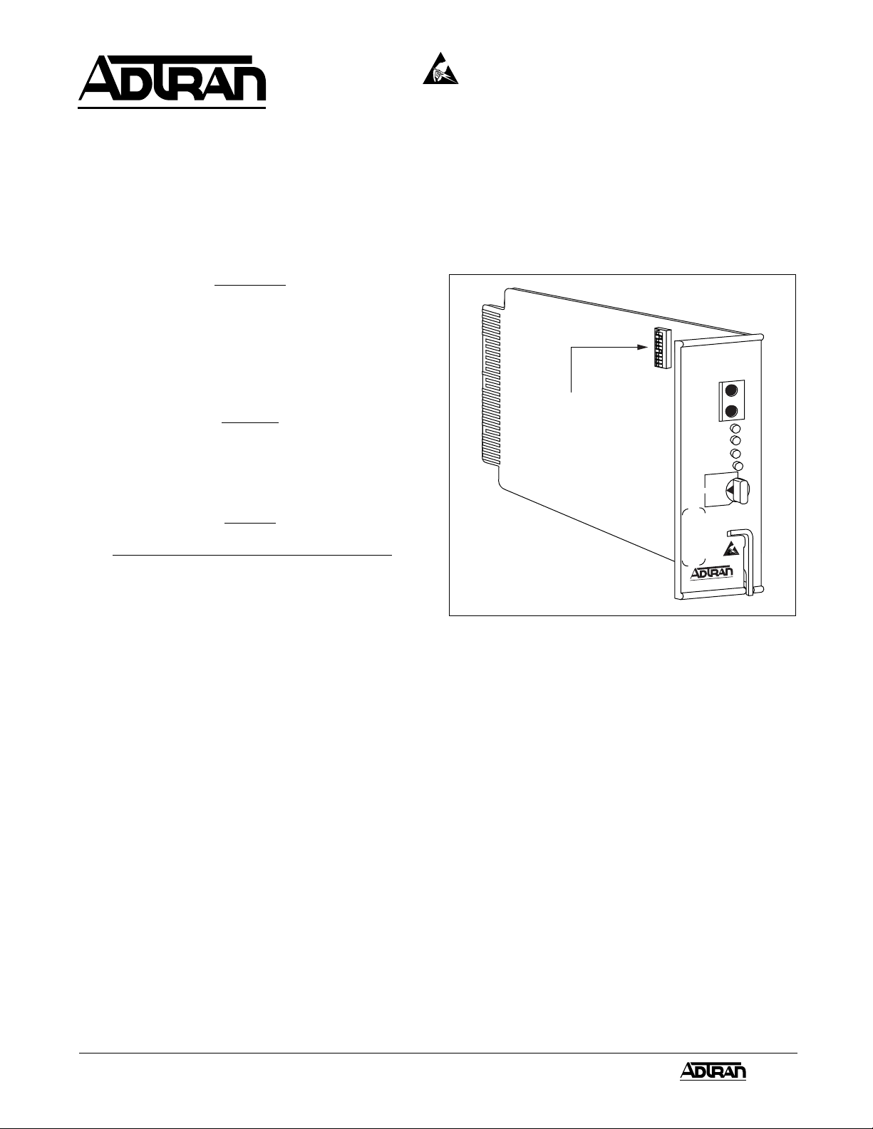
This practice is an installation and maintenance guide
for the ADTRAN Office Channel Unit Dataport (D4-OCU
DP) with Extended Transmit Range1 (ETR). Figure 1 is
an illustration of the unit. A detailed product description
is found in ADTRAN D4-OCU DP Description Practice,
Section 61107005L2-2.
The Office Channel Unit Dataport (OCU DP) allows
access to the Dataphone® Digital Service (DDS) or
Basic Digital Service using existing 4-wire metallic
facilities and D4 channel banks equipped for dataport
operation. In addition to this interchangeability, the
ADTRAN D4-OCU DP contains the following
enhancements:
• Extended loop range2 (45 dB receiver range
when operated at all rates)
• Intermediate rate of 19.2 kbps; special format
________________________________________
1
Covered under I.N.C. patent number 4,887,278
Dataphone is a registered trademark of AT&T
2
Covered under ADTRAN patent number 4,759,035
3
Covered under I.N.C. Patent No. 4,862,480
3
Figure 1. ADTRAN D4-OCU DP
• Switched 56 capability
• Latching and normal loopbacks
• Latching loopback capability in SW56 mode
• Loss of sealing current disconnect
• Poor loop signal quality disconnect
• Hardware signaling selection
• 45 dB range at all rates
• Faceplate Bantam jacks
• Four diagnostic faceplate indicators
• Extended transmit range
Furnished with common equipment and individual channel
units, the D4 channel bank is a digital terminal providing
multiple-channel access to T carrier lines. The dataport
is a D4-type channel unit which allows direct digital
access to a T carrier time slot, avoiding the normal
analog-to-digital conversion required in a voice channel
unit.
1Section 61107005L2-5, Issue 361107.005L2-5C
Page 2
In the DDS system, an OCU DP located at an end office
interfaces the customer to the T carrier system. A 4-wire
loop is terminated at the customer premises by a data
service unit (DSU) or a channel service unit (CSU). It can
be used in the hub office, intermediate office, end office,
or SLC® terminal to extend the DDS network to that office
which has previously served voice channels exclusively.
SC
19.2
9.6
38.4
56
No rate selection
64
56
38.4
19.2
The ADTRAN All-Rate Extended Range D4-OCU DP is
interchangeable with the following AT&T units:
• Subrate OCU DP (J98726DB)
• 56 kbps OCU DP (J98726DE)
• All Rate OCU DP (J98726DJ)
The unit is also interchangeable with all previous and
current ADTRAN units including the following:
• All-Rate OCU DP (1102005A)
• All-Rate with 38.4/64 kbps OCU DP (1102006A)
• All-Rate OCU DP (1104005L9)
2. INSTALLATION
After unpacking the unit, immediately inspect it for
possible shipping damage. If damage is discovered, file
a claim immediately with the carrier and contact ADTRAN
Customer Service (see subsection 7).
The D4-OCU DP plugs directly into a WECO®, or
equivalent, D4 channel bank, ADTRAN General Purpose
Communication (GPC) shelves, or ADTRAN ACT-1241
channel bank. No installation wiring is required.
A sixteen-position rotary switch on the faceplate and an
internal ten-position slide switch (SW1) must be set prior
to installing the unit.
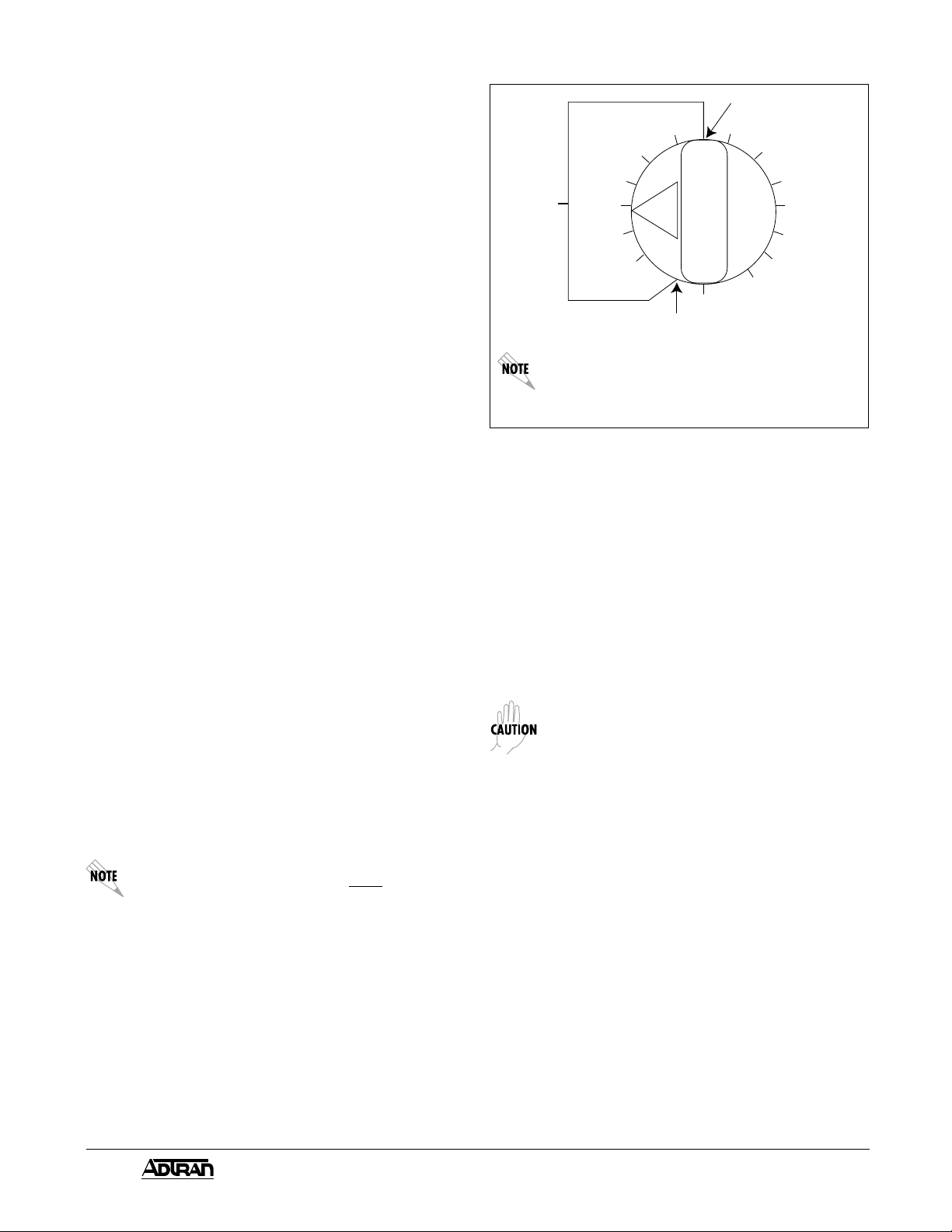
Sixteen-Position Rotary Faceplate Switch
The settings for the sixteen-position rotary switch select
loop rates of 2.4, 4.8, 9.6,19.2, 38.4, 56, SW56, or 64
kbps, and Secondary Channel (SC). Set the switch functions
as illustrated in Figure 2.
When 64 kbps is selected, normal loopbacks
are automatically disabled. Only latching
loopback may be used at this rate. When SW56
is selected as the operating rate, SW1-1 must
remain off.
________________________________________
SLC is a registered trademark of AT&T
WECO is a registered trademark of AT&T
4.8
2.4
SW56
No rate selection
9.6
4.8
2.4
Shown with 9.6 kbps Secondary Channel
selected. Two positions do not have rates
associated with them. The D4-OCU DP will not
function when these switch positions are set.
Figure 2. Rate Option Switch
Internal Switch Option Settings
The location of the ten-position slide switch is illustrated
in Figure 3. The option settings are provided in Table B.
SW1 is a ten-position slide switch which enables or
disables error correction, bank type, zero code
suppression, latching loopback, hardware A/B signaling,
quality monitoring, and extended transmit range.
If more than one bank type is selected (on), the OCU DP
will not function.
There are restrictions in the deployment of
38.4, 56, and 64 kbps with error correction in
a D4 bank. When the dataport is configured for
no error correction, a single timeslot is used
and the unit may be located in any channel slot
of the D4 bank. With 38.4, 56 and 64 kbps error
correction selected, the dataport generates a
parity byte for each data byte, thus occupying
two timeslots. If the standard D4 38.4, 56 and
64 kbps error correction option is selected, the
parity byte is inserted into the timeslot
immediately following the data. The specific
design of the D4 common equipment interacts
with the error correcting schemes and yields
the following deployment restrictions on a
38.4, 56 and 64 kbps dataport with error
correction:
a. All D4 Modes: Dataport may not be located
in channel slot 24.
b. D4 Modes 1, 2: Data and parity must be
confined to groups of six channel slots (i.e.,
slots 1-6, 7-12, 13-18, or 19-24.)
2 Section 61107005L2-5, Issue 3 61107.005L2-5C
Page 3

Switch
SW1-1
SW1-2
SW1-3
SW1-4
SW1-5
SW1-6
SW1-7
SW1-8
SW1-9
SW1-10
SW1
O
N
1
2 3 4 5 6 7 8 9 10
SW1
O
N
1 2 3 4 5 6 7 8 9 10
OFF
OFF
OFF
OFF
OFF
OFF
OFF
OFF
OFF
ERROR CORRECTION
D4
SLC-96 MODE I, III
SLC-96 MODE II
ZERO CODE SUPPRESSION
LATCHING LBK ENABLE
ENHANCED SWITCHED 56 (OBSOLETE)
AB SIGNALING
QUALITY MONITOR
ETR
BANK
TYPE
Figure 3. SW1
Table A. SW1 Option Settings
Function
On .... Activates error correction
Off ....Deactivates error correction
On.... Selects D4 bank type.
Off .... Unable to select D4 bank type.
On.... Selects SLC-96 bank, Mode I or III.
Off .... Unable to select SLC-96 bank, Mode I or III.
On.... Selects SLC-96 bank, Mode II.
Off .... Unable to select SLC-96 bank, mode II.
On.... Activates zero code suppression.
Off .... Disables zero code suppression.
On.... Enables latching loopback.
Off ....Disables latching loopback.
Leave switch in the off position to select SW56. Enhanced SW56 function has been obsoleted.
Off .... Selects SW56 mode.
On.... Enables use of hardware A/B signaling bits in SW56 mode.
Off .... Disable hardware A/B signaling.
On .... Enables loop signal quality monitoring. Loop disconnects upon detection of poor signal quality.
Off .... Disables loop signal quality monitoring.
On.... Enables extended transmit range. Transmit level is increased for 56 or 64 kbps loops with a loss in excess of
34 dB. Loss of sealing current (open line) overrides ETR. Unit is shipped with this switch in the off position.
Off .... Disables extended transmit range.
3. CONNECTIONS
The OCU DP occupies one card position in the D4
channel bank. The connector pin assignments are detailed
in Figure 4.
4. TESTING
In the case of equipment malfunction, use the
automated testing capability of the Serving Test Center
(STC) or the faceplate test connectors with portable KS20908/20909 or a functionally equivalent test set.
The faceplate contains Bantam jacks for manual testing
(see ADTRAN D4-OCU DP Description practice, Section
61107005L2-2, Testing, for manual testing information).
Loopback Tests
OCU, channel, and optional DSU loopbacks, both normal
and latching, may be activated by issuing the prescribed
commands in accordance with TA-TSY-000077. The
LOOPBACK LED is illuminated when OCU loopback or
channel loopback is activated.
3Section 61107005L2-5, Issue 361107.005L2-5C
Page 4

1
+5V
IN CLK
TNEN
TDATA
RSAB
RCLK
RWD
RSQ
-48V
R1
28
29
30
31
32
33
34
35
36
10
37
11
38
12
39
13
40
14
41
15
42
16
43
17
44
18
45
19
46
20
47
21
48
22
49
23
50
R
24
51
25
52
26
53
27
54
FRM GND
2
-12V
3
GND
+12V
4
GND
5
TWD
6
7
TSP
8
TSQ
9
RNPCM
RFA
TDCLK
RSP
RNDIS
-48R
T1
IZ
T
Figure 4. Connector Pin Assignments
This will cause the branch to be blocked at the next
junction (MJU or QMJU). The D4-OCU DP detects poor
received signal quality on the loop by monitoring for
illegal bipolar violations.
6. MAINTENANCE
The D4-OCU DP requires no routine maintenance to
operate properly. In case of equipment malfunction, use
the faceplate test connector and indicators to determine
the trouble source. The faceplate of the D4-OCU DP
contains Bantam test jacks for the KS-20908/20909 or a
functionally equivalent test set. All units contain LEDs as
described in subsection 4.
ADTRAN does not recommend that repairs be performed
in the field. Repair services may be obtained by returning
the defective unit to the ADTRAN Repair Department
(see subsection 7).
7. WARRANTY AND CUSTOMER SERVICE
ADTRAN will replace or repair this product within ten
years from the date of shipment, if the product does not
meet its published specifications or if it fails while in
service. For detailed warranty, repair, and return
information, refer to the ADTRAN Equipment Warranty
and Return Policy and Procedure.
Faceplate Indicators
The OCU DP has four faceplate LED indicators as
follows:.
LOOPBACK .......On for OCU or channel loopback.
IDLE CKT...........On for inactive data channel. Detects
the reception of the idle sequence
from the loop side (DSU/CSU to OCU).
NO SX................On for no sealing current. Indicates
detection of no sealing current on the
loop.
AUTO DIS ..........On for auto disconnect. Indicates a
loop disconnect due to poor signal
quality.
5. AUTO LOOP DISCONNECT
On multi-point networks, failure of a single node can
cause the entire network to be inoperable. To prevent
this, the D4-OCU DP incorporates an auto loop
disconnect feature. Loop disconnect occurs when
sealing current is absent or the quality monitor threshold
is exceeded.
If the quality monitoring option is enabled and poor
received signal quality is detected, the loop will be
disconnected and abnormal station control code
(10011110) will be sent toward the network.
Return Material Authorization (RMA) is required prior to
returning equipment to ADTRAN. ADTRAN does not
recommend that repairs be performed in the field.
For service, RMA requests, or further information, contact
one of the following numbers:
ADTRAN Customer Service:
Applications Engineering ................ (800) 615-1176
(pre-sales support and inquiries)
Technical Support ........................... (800) 726-8663
(post-sales; have unit serial number available)
Sales ............................................... (800) 827-0807
RMA (Repair Service)..................... (205) 971-8722
Repair and Return Address:
ADTRAN, Inc.
Customer Service Department
901 Explorer Boulevard
Huntsville, Alabama 35806-2807
4 Section 61107005L2-5, Issue 3 61107.005L2-5C
 Loading...