

Page 1

ATLAS 890
System Manual
1200321L1 ATLAS 890 Chassis
1200322L1 System Controller Module
1200344L1 AC Power Supply
1200345L1 DC Power Supply
61200321L1-1A
May 2001
Page 2

Trademarks
Any brand names and product names included in this manual are trademarks, registered
trademarks, or trade names of their respective holders.
To the Holder of the Manual
The contents of this manual are current as of the date of publication. ADTRAN reserves
the right to change the contents without prior notice.
In no event will ADTRAN be liable for any special, incidental, or consequential damages
or for commercial l os ses even if ADTRAN has bee n a dvi sed t h er eof a s a r es u lt o f iss ue of
this publication.
901 Explorer Boulevard
P.O. Box 140000
Huntsville, AL 35814-4000
Phone: (256) 963-8000
©2001 ADTRAN, Inc.
All Rights Reserved.
Printed in U .S.A.
ATLAS 890 System Manual © 2001 ADTRAN, Inc.
Page 3

About this Manual
This manual provides a complete description of the ATLAS 890 system and system
software. The purpose of this manual is to provide the techni cian, system administra tor,
and manage r with genera l and specific information related to the planning, installation,
operation, and maintenance of the ATLAS 890. This manual is arranged so that needed
information can be quickl y and easi ly found. The fo llowing i s an over view of t he conten ts.
Section 1 System Description
Provides managers with an overview of the ATLAS 890 system.
Section 2 Engineering Guidelines
Provides information to assist network designers with incorporating the ATLAS 890
system into their networks.
Section 3 Network Turnup Procedure
Provides step-by-step instructions on how to install the ATLAS 890 unit, determine the
parameters for the system, install the network and option modules, and power up the
system.
Section 4 User Interface Guide
Explains the VT-100 and Telnet interfaces, the VT-100 use r inter face conv entions, a nd the
ATLAS 890 top-level menu tree.
Section 5 Detail Level Procedures (DLP)
Provides the detail level procedures called out in Section 3, NTP.
Section 6 System Event Logging
Explains the System Event Logging messages for the ATLAS 890 and provides
instructions for confi guring the Ev ent Log.
Glossary
Revision History
This is the 1st issue of this manual.
© 2001 ADTRAN, Inc. ATLAS 890 System Manual
Page 4

Notes provide additional useful information.
Cautions signify information that could prevent service interruption.
Warnings provide information that could prevent damage to the equipment or
endangerment to human life.
Safety Instructions
When using your telephone equipment, please follow these basic safety precautions to
reduce the r isk of fire, electrical sh ock, or personal injury:
1. Do not use this product near water, such as a bathtub, wash bowl, kitchen sink, laundry tub, in a wet basement, or near a swimming pool.
2. Avoid using a telephone (other than a cordless-typ e) during an electrical stor m. The re
is a remote risk of shock from lightning.
3. Do not use the telephone to report a gas leak in the vicinity of the leak.
4. Use only the power cord, power supply, and/or batteries indicated in the manual. Do
not dispose of batteries in a fire. They may explode. Check with local codes for special disposal instructions.
Save These Important Safety Instructions
ATLAS 890 System Manual © 2001 ADTRAN, Inc.
Page 5

Affidavit Requirements for Connection to Digital Services
• An affidavit is required to be given to the telephone company whenever digital terminal equipment
without encoded analog content and billing protection is used to transmit digital signals containing
encoded analog content wh ic h are int ende d for eventual conversion i nto voiceband analog signals and
transmitted on the network.
• The affidavit shall affirm that either no encoded analog content or billing information is being transmitted or that the output of th e dev ice me et s Par t 68 en cod ed analog content or billi ng pr ote ct ion specifications.
• End user/customer will be responsible for filing an affidavit with the local exchange carrier when connecting unprotected customer premise equipment (CPE) to 1.544 Mbps or subrate digital services.
• Until such time as subrate digital terminal equipment is registered for voice applications, the affidavit
requirement for subrate services is waived.
© 2001 ADTRAN, Inc. ATLAS 890 System Manual
Page 6

Affidavit for Connection of Customer Premises Equipment
to 1.544 Mbps and/or Subrate Digital Services
For the work to be performed in the certified territory of ___________________(telco name)
State of ________________
County of ________________
I, _______________________ (name), _____________________________(business address),
____________________ (telephone number) being duly sworn, state:
I have responsibility for the operation and maintenance of the terminal equipment to be
connected to 1.544 Mbps and/or ________ subrate digital services. The terminal equipment
to be connected complies with Part 68 of the FCC rules except for the encoded analog
content and billing protection specifications. With respect to encoded analog content and
billing protection:
( ) I attest that all operations associated with the establishment, maintenance, and adjustment of
the digital CPE with respect to analog content and encoded billing protection information continuously complies with Part 68 of the FCC Rules and Regulations.
( ) The digital CPE does not transmit digital signals containing encoded analog content or billing
information which is intended to be decoded within the telecommunications network.
( ) The encoded analog content and billing protection is factory set and is not under the control of
the customer.
I attest that the operator(s)/maintainer(s) of the digital CPE responsible for the establishment, maintenance, and adjustment of the encoded analog content and billing information
has (have) been trained to perform these functions by successfully having completed one of
the following (check appropriate blocks):
( ) A. A training course provided by the manufacturer/grantee of the equipment used to encode
analog signals; or
( ) B. A training course provided by the customer or authorized representative, using training
materials and instructions provided by the manufacturer/grantee of the equipment used to
encode analog signals; or
( ) C. An independent training course (e.g., trade school or technical institution) recognized by
the manufacturer/grantee of the equipment used to encode analog signals; or
( ) D. In lieu of the preceding training requirements, the operator(s)/maintainer(s) is (are) under
the control of a supervisor trained in accordance with _________ (circle one) above.
ATLAS 890 System Manual © 2001 ADTRAN, Inc.
Page 7

I agree to provide ______________________ (telco’s name) with proper documentation to
demonstrate compliance with the information as provided in the preceding paragraph, if so
requested.
_________________________________Signature
_________________________________Title
_________________________________ Date
Transcribed and sworn to before me
This ________ day of _______________, _______
_________________________________
Notary Public
My commission expires:
_________________________________
© 2001 ADTRAN, Inc. ATLAS 890 System Manual
Page 8

FCC regulations require that the following information be provided in this manual:
1. This equipment complies with Part 68 of FCC rules. On the back of the equipment housing is a label
showing the FCC regis tration number and r inger eq uivalence number (REN). If reque sted, pro vide this
information to the telephone company.
2. If this equipment causes harm to the telephone network, the telephone company may temporarily discontinue service. If possible, advance notification is given; otherwise, notification is given as soon as
possible. T he telephone company will advise the customer of the right to file a complaint with the
FCC.
3. The telephone company may make changes in its facilities, equipment, operations, or procedures that
could affect the proper operation of this equipment. Advance notification and the opportunity to maintain uninterrupted service are given.
4. If experiencing difficulty with this equipment, please contact ADTRAN for repair and warranty information. The telephone company ma y requi re t his e quipment t o be di sconne cted f rom the n etwork until
the problem is corrected or it is certain the equipment is not malfunctioning.
5. This unit contains no user-serviceable parts.
6. An FCC compliant telephone cord with a modular plug is provided with this equipment. This equipment is designed to be connected to the telephone network or premises wiring using an FCC compatible modular jack, which is Part 68 compliant.
7. The following information may be required when applying to the local telephone company for a dialup line for the V.34 modem:
Service Type REN FIC USOC
Loop Start 1.6B/0.8A 02LS2 RJ-11C
8. The REN is useful in determining the quantity of devices you may connect to your telephone line and
still have all of those devices ring when your number is called. In most areas, the sum of the RENs of
all devices should not exceed five. To be certain of the number of devices you may connect to your
line as determined by th e REN, call your tele phone compan y to determin e the maximum REN for your
calling area.
9. This equipment may not be used on coin service provided by the telephone company. Connection to
party lines is subject to state tariffs. Contact your state public utility commission or corporation commission for i nformation.
ATLAS 890 System Manual © 2001 ADTRAN, Inc.
Page 9

Federal Communications Commission Radio Frequency Interference Statement
This equipment has been tested and found to comply with the limits for a Class A digital device, pursuant
to Part 15 of the FCC Rules. These limits are designed to provide reasonable protection against harmful
interference when the equipment is operated in a commercial environment. This equipment generates,
uses, and can radiate radio frequency energy and, if not installed and used in accordance with the instruction manual, may cause harmful interference to radio frequencies. Operation of this equipment in a residential area is likely to ca use harmful interference in which case the user will be required to correct the
interference at his own expense.
Shielded cables must be used with th is unit to ensure complia nce with Class A FCC limits.
Changes or modifications to this unit not expressly approved by the party
responsible for compli ance could void the user's authority to operate the equi pment.
Canadian Emissions Requirements
This digital apparatus does not exceed the Class A limits for radio noise emissions from digital apparatus
as set out in the interference-causing equipment standard entitled “Digital Apparatus,” ICES-003 of the
Department of Communications.
Cet appareil nuerique respecte les limites de bruits radioelectriques applicables aux appareils numeriques
de Class A prescrites dans la norme sur le materiel brouilleur: “A ppar ei ls Nume ri ques , ” NMB-003 edictee
par le ministre des Communications.
© 2001 ADTRAN, Inc. ATLAS 890 System Manual
Page 10

Canadian Equipment Limitations
Notice: The Canadian Industry and Science Canada label identifies certified equipment. This certification
means that the equipment meets certain telecommunications network protective, operational, and safety
requirements. The Department does not guarantee the equipment will operate to the user’s satisfaction.
Before installing this eq uipment, use rs should en sure that it is p ermissible to be connecte d to the facilities
of the local telecommunications company. The equipment must also be installed using an acceptable
method of connection. In some cases, the company’s inside wiring associated with a single line individual
service may be extended by means of a certified connector assembly (telephone extension cord). The customer should be aware that compliance with the above limitations may not prevent degradation of service
in some situations.
Repairs to certif ied equipment should be ma de b y an authorized Canadia n mai nte nan ce facility designa ted
by the supplier. Any repairs or alterations made by the user to this equipment, or equipment malfunctions,
may give the telecommunications company cause to request the user to disconnect the equipment.
Users should ensure for their own protection that the electrical ground connections of the power utility,
telephone lines and int ernal metallic wate r pi pe sy st em, if present, are connected to get her. This precaution
may be particularly important in rural areas.
Users should not attempt to make such connections themselves, but should contract the
appropriate electric inspection authority, or an electrician, as appropriate.
The Load Number (LN) a ssigne d t o each termi nal de vice denote s the per centa ge of the t otal load to be con nected to a telephone loop which is used by the device, to prevent overloading. The termination on a loop
may consist of any combination of devices subject only to the requirement that the total of the Load Numbers of all devices does not exceed 100.
ATLAS 890 System Manual © 2001 ADTRAN, Inc.
Page 11

Warranty and Customer Service
ADTRAN will replace or rep air t his produc t with in fi ve year s fro m the dat e of s hi pment if it d oes not meet
its published specifications or fails while in serv ice. For det ailed warran ty, repair, and return informati on
refer to the ADTRAN Equipment Warranty and Repair and Return Policy Procedure.
Return Material Authorization (RMA) is required prior to returning equipment to ADTRAN.
For service, RMA requests, or further information, contact one of the numbers listed at the end of this section.
LIMITED PRODUCT WARRANTY
ADTRAN warrants that for five (5) years from the date of shipment to Customer, all products manufactured by ADTRAN will be free from defects in materials and workmanship. ADTRAN also warrants that
products will conform to the applicable specifications and drawings for such products, as contained in the
Product Manual or in ADTRAN's internal specifications and drawings for such products (which may or
may not be refl ect ed i n the Product Manual) . This warranty o nly a ppl ies if Customer giv es ADTRAN written notice of defects during the warranty period. Upon such notice, ADTRAN will, at its option, either
repair or replace the defective item. If ADTRAN is unable, in a reasonable time, to repair or replace any
equipment to a condition as warranted, Customer is entitled to a full refund of the purchase price upon
return of the equipment to ADTRAN. This warranty applies only to t he or igi nal purchaser and is not tr ans ferable without ADTRAN's express written permission. This warranty becomes null and void if Customer
modifies or alters the equipment in any way, other than as specifically authorized by ADTRAN.
EXCEPT FOR THE LIMITED WARRANTY DESCRIBED ABOVE, THE FOREGOING CONSTITUTES THE SOLE AND EXCLUSIVE REMEDY OF THE CUSTOMER AND THE EXCLUSIVE LIABILITY OF ADTRAN AND IS IN LIEU OF ANY AND ALL OTHER WARRANTIES (EXPRESSED
OR IMPLIED). ADTRAN SPECIFICALLY DISCLAIMS ALL OTHER WARRANTIES, INCLUDING
(WITHOUT LIMITATION), ALL WARRANTIES OF MERCHANTABILITY AND FITNESS FOR A
PARTICULAR PURPOSE. SOME STATES DO NOT ALLOW THE EXCLUSION OF IMPLIED
WARRANTIES, SO THIS EXCLUSION MAY NOT APPLY TO CUSTOMER.
In no event will ADTRAN or its suppliers be liable to Customer for any incidental, special, punitive,
exemplary or consequential damages experienced by either
Customer or a third party (including, but not limited to, loss of data or information, loss of profits, or loss
of use). ADTRAN is not liable for damages for any c ause
whatsoever (whether based in contract, tort, or otherw is e) i n exce ss of the amount paid for the item. Some
states do not allow the limitation or exclusion of liability for incidental or consequential damages, so the
above limitation or exclusion may not apply to Customer.
© 2001 ADTRAN, Inc. ATLAS 890 System Manual
Page 12

Customer Service, Product Support Information, and Training
ADTRAN will replace or repair this pr oduct wit hin five ye ars fr om the dat e of shi pment if the pro duct does
not meet its published specification, or if it fails while in service.
A return mate rial authorization (RMA) is required prior to returnin g equipment to ADTRAN. For service,
RMA requests, training, or more information, see the toll-free contact numbers given below.
Presales Inquiries and Applications Support
Please contact your local distributor, ADTRAN Applications Engineering, or ADTRAN Sales:
Applications
(800) 615-1176
Engineering
Sales (800) 827-0807
Post-Sale Support
Please contact your local distributor first. If your local distributor cannot help, please contact ADTRAN
Technical Support and have the unit serial number available.
Technical Support (888) 4ADTRAN
The Custom Extended Service s (ACES) program offers mul tiple type s and levels of service plans which al low you to choose the kind of assistance you need. For questions, call the ACES Help Desk.
ACES Help Desk (888) 874-2237
Repair and Return
If ADTRAN Technical Support d et ermi nes that a repair is needed, Technical Suppor t will coordinate wit h
the Custom and Product Service (CAPS) department to issue an RMA number. For information regarding
equipment currently in ho use or possible fee s associated with repa ir, contact CAPS direc tly at the following
number:
CAPS Department (256) 963-8722
Identify the RMA number clearly on the package (below address), and return to the following address:
ADTRAN Customer and Product Service
901 Explorer Blvd.
Huntsville, Alabama 35806
RMA # _____________
ATLAS 890 System Manual © 2001 ADTRAN, Inc.
Page 13

Training
The Enterprise Network (EN) Tec hnical Training offe rs training on our most popular products. The se courses
include overviews on product feat ures and functions whil e covering applications of ADTRAN's pr oduct lines.
ADTRAN provides a variety of training opt ions, including customized traini ng and courses taught at our facilities or at your sit e. For more i nformation about training, please contact your Territo ry Manager or the Enterprise Training Coordinator.
Training - phone (800) 615-1176, ext. 7500
Training - fax (256) 963-6700
Training - email training@adtran.com
© 2001 ADTRAN, Inc. ATLAS 890 System Manual
Page 14

ATLAS 890 System Manual © 2001 ADTRAN, Inc.
Page 15

61200321L1-1A
ATLAS 890
Section 1, System Description
Page 1 of 6
SYSTEM DESCRIPTION
This section of ADTRAN’ s A TLAS 8 90 Syst em Manual is design ed for use by network engineers, planne rs,
and designers for overview information about the ATLAS 890.
It contains general information and describes physical and operational concepts, card functions, network
relationships, provisioning, testing, alarm status, and system monitoring. This section should be used in
conjunction with Section 2, Engineering Guidelines, of the system manual.
System Overview . . . . . . . . . . . . . . . . . . . . . . . . . . . . . . . . . . . . . . . . . . . . . . . . . . . . . . . . . . . . . . . . 2
Features and Benefits . . . . . . . . . . . . . . . . . . . . . . . . . . . . . . . . . . . . . . . . . . . . . . . . . . . . . . . . . . . . 2
Configuration and Management . . . . . . . . . . . . . . . . . . . . . . . . . . . . . . . . . . . . . . . . . . . . . . . . . . 2
Software Upgradeable . . . . . . . . . . . . . . . . . . . . . . . . . . . . . . . . . . . . . . . . . . . . . . . . . . . . . . . . . 2
Signaling Support . . . . . . . . . . . . . . . . . . . . . . . . . . . . . . . . . . . . . . . . . . . . . . . . . . . . . . . . . . . . . 3
ISDN Switch Types . . . . . . . . . . . . . . . . . . . . . . . . . . . . . . . . . . . . . . . . . . . . . . . . . . . . . . . . . . . . 3
Dedicated Connection Maps. . . . . . . . . . . . . . . . . . . . . . . . . . . . . . . . . . . . . . . . . . . . . . . . . . . . . 3
Switched Connection Maps. . . . . . . . . . . . . . . . . . . . . . . . . . . . . . . . . . . . . . . . . . . . . . . . . . . . . . 3
Testing . . . . . . . . . . . . . . . . . . . . . . . . . . . . . . . . . . . . . . . . . . . . . . . . . . . . . . . . . . . . . . . . . . . . . 3
Performance Monitoring . . . . . . . . . . . . . . . . . . . . . . . . . . . . . . . . . . . . . . . . . . . . . . . . . . . . . . . . 3
Frame Relay . . . . . . . . . . . . . . . . . . . . . . . . . . . . . . . . . . . . . . . . . . . . . . . . . . . . . . . . . . . . . . . . . 3
PPP Switching. . . . . . . . . . . . . . . . . . . . . . . . . . . . . . . . . . . . . . . . . . . . . . . . . . . . . . . . . . . . . . . . 4
Option Modules . . . . . . . . . . . . . . . . . . . . . . . . . . . . . . . . . . . . . . . . . . . . . . . . . . . . . . . . . . . . . . . . . 4
ATLAS 890 System Controller Module (P/N 1200322L1). . . . . . . . . . . . . . . . . . . . . . . . . . . . . . . 4
Quad T1/PRI Option Module (P/N 1200185L3) . . . . . . . . . . . . . . . . . . . . . . . . . . . . . . . . . . . . . . 5
Quad E1/PRA Option Module (P/N 1200264L1). . . . . . . . . . . . . . . . . . . . . . . . . . . . . . . . . . . . . . 5
Quad Nx 56/64 Option Module (P/N 1200184L1) . . . . . . . . . . . . . . . . . . . . . . . . . . . . . . . . . . . . . 5
Quad USSI Option Module (P/N 4200261LX). . . . . . . . . . . . . . . . . . . . . . . . . . . . . . . . . . . . . . . . 5
Octal Basic Rate ISDN Option Module (1200186L2) . . . . . . . . . . . . . . . . . . . . . . . . . . . . . . . . . . 5
T3 Option Module (P/N 1200223L1). . . . . . . . . . . . . . . . . . . . . . . . . . . . . . . . . . . . . . . . . . . . . . . 5
T3 Option Module with Drop and Insert Interface (P/N 1200225L1). . . . . . . . . . . . . . . . . . . . . . . 5
8,16,24, 32 Channel Voice Compression Resource Modules (P/N 1200221Lx) . . . . . . . . . . . . . 5
Nx 56/64 IMUX Resource Module (P/N 1200262L1) . . . . . . . . . . . . . . . . . . . . . . . . . . . . . . . . . . 6
HDLC Resource Module (P/N 1200222L1). . . . . . . . . . . . . . . . . . . . . . . . . . . . . . . . . . . . . . . . . . 6
Modem-16 Resource Module (P/N 1200181L1) . . . . . . . . . . . . . . . . . . . . . . . . . . . . . . . . . . . . . . 6
Async-232 Option Module (P/N 1200182L1) . . . . . . . . . . . . . . . . . . . . . . . . . . . . . . . . . . . . . . . . 6
© 2001 ADTRAN, Inc. ATLAS 890 System Manual
Page 16

61200321L1-1A
ATLAS 890
Section 1, System Description
Page 2 of 6
1. SYSTEM OVERVIEW
The ATLAS 890 is a modular, highly scalable platform that provides robust solutions for the wide-area
communication needs of medium-to-large corporations and network access providers. The ATLAS 890 is
an Integrated Access System with extensive support of dedicated bandwidth management and access
switching.
PLUS
The ATLAS 890 is a higher bandwidth version of the ATLAS 800
CPU and powerful communications drivers which supports applications such as frame relay and call
switching.
The ATLAS 890 architecture als o incl udes a packet switc hing an d a circu it switc hing bu ssi ng sche me. The
result is a system capable of supporting bandwidth requirements of up to 30 T1 or Primary Rate ISDN
(PRI) circuits. Designed for standalone or rackmount, the ATLAS 890 Base Unit provides 2
hot-swappable, redundant system controller slots and up to 16 expansion slots that accommodate
hot-swappable option modules and up to 4 hot-swappable, redundant power supplies for a variety of
applications. A 10/100Bas eT Ethernet connecti on for IP rou ting and net work management is standar d with
the ATLAS 890 System Controller Module.
. It contains a high-performance
With the ATLAS 890, you can consolidate your voice, data, and video applications into a single platform
while optimizing wide area bandwidth and reducing equipment costs. The ATLAS 890 architecture and
expansion slots allow for a variety of modules, making it one of the most versatile access systems on the
market.
2. FEATURES AND BENEFITS
The following is a brief list of ATLAS 890 features and benefits:
Configuration and Management
• VT-100 Emulation
• SNMP, per MIB II (RFC1213), DS1 MIB (RFC1406), and ADTRAN private MIBs
•Telnet
• Dial up rem ote management via external analog modem
• Six levels of password protection and privileges
Software Upgradeable
• Flash memory
• TFTP download
• XMODEM via control port
ATLAS 890 System Manual © 2001 ADTRAN, Inc.
Page 17

Signaling Support
• ISDN D Channel
• Robbed bit, E&M, Ground Start, Loop Start
• Convert between Robbed Bit Signaling and ISDN D Channel
• Direct Inward Dialing
ISDN Switch Types
• 5ESS™, DMS-100™, National ISDN, 4ESS™
Dedicated Connection Maps
• Up to five connection maps
• Time of day/day of week configurable
• Preserves signaling through cross-connect
• No effect on non-configured channels
61200321L1-1A
ATLAS 890
Section 1, System Description
Page 3 of 6
Switched Connection Maps
• Inbound and outbound call filtering and blocking
Testing
• Local and remote: payload/line, V.54 (depending on installed modules)
• Patterns: 511, QRSS, all ones, all zeros (depending on installed modules)
Performance Monitoring
• Reports: Information stored for last 24 hours in 15 minute increments
• Performance statistics per TR54016, T1.403, RFC1406
• Alarm reporting per TR54016, T1.403
Frame Relay
• Routes Internet Protocol (IP) traffic between a public frame relay network, a private frame relay network, or a point-to-point (PPP) network and the Ethernet port.
• Concentrates IP tr affi c from a p ublic o r priv ate fr ame rel ay networ k to one or more se rial ports (V.35).
The protocol passed over the serial port is frame relay (RFC 1490 encapsulation).
• Passes Systems Network Architecture (SNA), Bisync, and other legacy protocols between a public or
private frame relay network and an external DTE running frame relay to ATLAS.
• Performs voice compression/decompression (G.723.1) and interfaces to either a Private Branch Exchange (PBX) or the Publ ic Switch ed Telephone Network (PSTN) . (This fea ture req uires an a dditional
option module, the VCOM Module—P/N 1200221Lx.)
• Supports LMI, Annex D, or Annex A signaling on frame relay connections.
© 2001 ADTRAN, Inc. ATLAS 890 System Manual
Page 18

61200321L1-1A
ATLAS 890
Section 1, System Description
Page 4 of 6
PPP Switching
• Supports up to 100 simultaneous PPP connections.
• Performs PAP, CHAP, or EAP authentication methods on a per connection basis.
• Includes keepalive functionality for PPP connections.
• Provides capability for numbered or unnumbered PPP interfaces.
3. OPTION MODULES
The ATLAS 890 has a system controller module and 15 option modules:
• ATLAS 890 System Controller Module (P/N 1200322L1)
• Quad T1/PRI Option Module (P/N 1200185L3)
• Quad E1/PRA Option Module (P/N 1200264L1)
• Quad Nx 56/64 Option Module (P/N 1200184L1)
• Quad USSI Option Module (P/N 4200261Lx)
• Octal Basic Rate ISDN Option Module (1200186L2)
• T3 Option Module (P/N 1200223L1)
• T3 Option Module with Drop and Insert Interface (P/N 1200225L1)
• 8,16,24, 32 Channel Voice Compression Resource Modules (P/N 1200221Lx)
• Nx 56/64 IMUX Resource Module (P/N 1200262L1)
• HDLC Resource Module (P/N 1200222L1)
• Modem-16 Resource Module (P/N 1200181L1)
• Async-232 Option Module (P/N 1200182L1)
Each option module is hot-swappable with configuration restored upon replacement.
Replacing an option module with a different module type will result in configuration loss.
Each option module has a variety of performance and alarm status information. Several features of each
module are user-configu rable, although default va lue s re flect the most common confi gura ti ons. All option
modules contain an extensive self-test as well as tests designed for the technology they incorporate.
ATLAS 890 System Controller Module (P/N 1200322L1)
In addition to controlling the shelf and its contents, the system con troller modules serve as the user interface. The operator provisions and m onitors all modules in the system, either locally or remotely, via the
system controller inte rf ace. The system controlle rs provi si on the option cards in the she lf via the fa ceplate
RJ-45 Admin connector of the act ive syst em controller and a VT-1 00 termina l (see Figur e 4). Addi tionall y,
a 10/100 Base-T Ethernet interface is provided for Telnet access.
ATLAS 890 System Manual © 2001 ADTRAN, Inc.
Page 19

61200321L1-1A
ATLAS 890
Section 1, System Description
Page 5 of 6
Quad T1/PRI Option Module (P/N 1200185L3)
The Quad T1/PRI Option Module provides four c hann el ize d T1 or PRI interfa ces . Ea ch int er fa ce can operate independently in DS-1, DSX-1, or PRI mode, and any port can deliver timing for the system.
Quad E1/PRA Option Module (P/N 1200264L1)
The Quad E1/PRA Option Module provides four channelized E1 or PRA interfaces using a supplied
120 ohm DB-15 converter cable. The Quad E1/PRA Option Module may also be purchased to include
BNC converter cables (P/N 4200264L1). This interface operates in CCS or CAS signaling mode and can
deliver timing for the system.
Quad Nx 56/64 Option Module (P/N 1200184 L 1)
The Quad Nx 56/64 module provides four synchronous V.35 DTE ports (using supplied DB-78 to V.35
converter cables) tha t ca n ope rat e f rom 56K to 2. 048 Mbps in st eps of 56 or 64 kbps . Any por t ca n del ive r
timing for t he system.
Quad USSI Option Module (P/N 4200261LX)
The Quad USSI Option Module provides four synchronous DTE ports that can operate from 56K to
2.048 Mbps in steps of 56 or 64 kbps. The DTE ports available (using adapter cables) are: EIA-530, EIA-
530A, RS-449, RS-232, and CCITT X.21. Any port can deliver timing for the system.
Octal Basic Rate ISDN Option Module (1200186L2)
The Octal Basic Rate ISDN module provides eight Basic Rate ISDN (BRI) U interfaces, each capable of
operating in either NT or LT mode. Any port can deliver timing for the system.
T3 Option Module (P/N 1200223L1)
The T3 Option Module provides a single channelized T3 interface that allows bandwidth management of
up to 28 T1s. Functions as a T3 DSU/CSU, M13 multiplexer, and 3/1/0 timeslot interchange DACS. The
T3 clock or any of the odd T1s contained in the T3 circuit may deliver timing for the system.
T3 Option Module with Drop and Insert Interface (P/N 1200225L1)
The T3 Option Module with Drop and Insert Interface provides a single channelized T3 interface for primary service and an additional drop and insert interface for passing T3 channels (in T1 pairs) to a secondary channelized T3 device. Functions as a T3 DSU/CSU, M13 multiplexer, and 3/1/0 timeslot interchange
DACS. The T3 clock or any of the odd T1s contained in the T3 circuit may deliver timing for the system.
8,16,24, 32 Channel Voice Compression Resource Modules (P/N 1200221Lx)
The Voice Compression Module (VCOM Module) combines with other ATLAS 890 components to
implement voice over frame relay (VoFR) capability. The Voice Compression Resources modules support
8, 16, 24, or 32 simultaneous compressed calls using G.723.1 or Netcoder compression algorithms.
© 2001 ADTRAN, Inc. ATLAS 890 System Manual
Page 20

61200321L1-1A
ATLAS 890
Section 1, System Description
Page 6 of 6
Nx 56/64 IMUX Resource Module (P/N 1200262L1)
The Nx 56/64 IMUX Resource Option Module supports multiple, independent BONDING sessions with
each session capable of using from 2 to 32 channels of 56K or 64K data. The Nx 56/64 IMUX Resource
Module combines with other ATLAS 890 components to provide a flexible disaster recovery system.
HDLC Resource Module (P/N 1200222L1)
Certain ATLAS applications require a large number of High-level Data Link Control (HDLC) controllers
beyond the 35 supplied on the system controller module. The HDLC Resource Module contains 128
HDLC controllers and is used when the application requirements call for more HD LC controllers than are
provided with the oth er ATLAS hardware c omponent s. The HDLC Res ource Modu le pro vides n o physi cal
interfaces.
Modem-16 Resource Module (P/N 1200181L1)
The Modem-16 Resource Module is a high-capacity card for the ATLAS Integrated Access System, capable of processing 16 modem calls and 16 ISDN calls. Modem or ISDN calls are presented to ATLAS via
one or more Primary Rate ISDN (PRI), Basic Rate ISDN (BRI), or T1 circuits. The Modem-16 Resource
Module can be used in cooperation with the Safe-T-Net feature of the ATLAS 890 to provide a V.34 disaster recovery solution.The Modem-16 Resource Module combines with the Async-232 Module to enable
dial-up access for up to 32 users. The Modem-16 Resource Module provides no physical interfaces.
Async-232 Option Module (P/N 1200182L1)
The Async-232 Module combines with the ATLAS 890 components to provide solutions for a variety of
wide area networking (WAN) applications. Providing sixteen asynchronous EIA-232 data terminal equipment (DTE) ports, the Async-232 Module serves as the interface to terminal servers and other DTE equipment. Each port of the Async-232 Module can be configured to operate at any standard asynchronous rate
up to 115.2 kbps. The Async-232 Module is only supported in dial-up applications (using the Modem-16
Resource Module) and is not a valid interface for TDM data.
ATLAS 890 System Manual © 2001 ADTRAN, Inc.
Page 21

61200321L1-1A
ATLAS 890
Section 2, Engineering Guidelines
Page 1 of 22
ENGINEERING GUIDELINES
ONTENTS
C
Equipment Dimensions . . . . . . . . . . . . . . . . . . . . . . . . . . . . . . . . . . . . . . . . . . . . . . . . . . . . . . . . . . . 3
Power Requirements . . . . . . . . . . . . . . . . . . . . . . . . . . . . . . . . . . . . . . . . . . . . . . . . . . . . . . . . . . . . . 3
AC System . . . . . . . . . . . . . . . . . . . . . . . . . . . . . . . . . . . . . . . . . . . . . . . . . . . . . . . . . . . . . . . . . . 3
DC System . . . . . . . . . . . . . . . . . . . . . . . . . . . . . . . . . . . . . . . . . . . . . . . . . . . . . . . . . . . . . . . . . . 3
Reviewing the front Panel Design . . . . . . . . . . . . . . . . . . . . . . . . . . . . . . . . . . . . . . . . . . . . . . . . . . . 3
ACO Switch. . . . . . . . . . . . . . . . . . . . . . . . . . . . . . . . . . . . . . . . . . . . . . . . . . . . . . . . . . . . . . . . . . 4
CRAFT Port. . . . . . . . . . . . . . . . . . . . . . . . . . . . . . . . . . . . . . . . . . . . . . . . . . . . . . . . . . . . . . . . . . 4
Front Panel LEDs . . . . . . . . . . . . . . . . . . . . . . . . . . . . . . . . . . . . . . . . . . . . . . . . . . . . . . . . . . . . . 4
Reviewing the Rear Panel Design . . . . . . . . . . . . . . . . . . . . . . . . . . . . . . . . . . . . . . . . . . . . . . . . . . . 7
Admin Port . . . . . . . . . . . . . . . . . . . . . . . . . . . . . . . . . . . . . . . . . . . . . . . . . . . . . . . . . . . . . . . . . . 8
10/100BaseT Connection . . . . . . . . . . . . . . . . . . . . . . . . . . . . . . . . . . . . . . . . . . . . . . . . . . . . . . . 8
Alarm Relay Connection . . . . . . . . . . . . . . . . . . . . . . . . . . . . . . . . . . . . . . . . . . . . . . . . . . . . . . . . 9
External Input Connection. . . . . . . . . . . . . . . . . . . . . . . . . . . . . . . . . . . . . . . . . . . . . . . . . . . . . . . 9
Option Module Interfaces . . . . . . . . . . . . . . . . . . . . . . . . . . . . . . . . . . . . . . . . . . . . . . . . . . . . . . . . 10
Quad T1/PRI Option Module (P/N 1200185L3) . . . . . . . . . . . . . . . . . . . . . . . . . . . . . . . . . . . . . 10
Quad E1/PRA Option Module (P/N 1200264L1). . . . . . . . . . . . . . . . . . . . . . . . . . . . . . . . . . . . . 10
Quad Nx 56/64 Option Module (P/N 1200184L1) . . . . . . . . . . . . . . . . . . . . . . . . . . . . . . . . . . . . 11
Quad USSI Option Module (P/N 1200261L1) . . . . . . . . . . . . . . . . . . . . . . . . . . . . . . . . . . . . . . . 13
Octal BRI Option Module (P/N 1200186L2) . . . . . . . . . . . . . . . . . . . . . . . . . . . . . . . . . . . . . . . . 17
Async-232 Option Module (P/N 1200182L1) . . . . . . . . . . . . . . . . . . . . . . . . . . . . . . . . . . . . . . . 18
T3 Option Module (P/N 1200223L1). . . . . . . . . . . . . . . . . . . . . . . . . . . . . . . . . . . . . . . . . . . . . . 18
T3 Drop and Insert Option Module (P/N 1200225L1) . . . . . . . . . . . . . . . . . . . . . . . . . . . . . . . . . 19
At-A-Glance Specifications . . . . . . . . . . . . . . . . . . . . . . . . . . . . . . . . . . . . . . . . . . . . . . . . . . . . . . . 20
IGURES
F
Figure 1. ATLAS 890 Front Panel Layout . . . . . . . . . . . . . . . . . . . . . . . . . . . . . . . . . . . . . . . . . . . . 3
Figure 2. ATLAS 890 Rear Panel . . . . . . . . . . . . . . . . . . . . . . . . . . . . . . . . . . . . . . . . . . . . . . . . . . 7
ABLES
T
Table 1. CRAFT Port Pinout . . . . . . . . . . . . . . . . . . . . . . . . . . . . . . . . . . . . . . . . . . . . . . . . . . . . . . 4
Table 2. ATLAS 890 Front Panel Description . . . . . . . . . . . . . . . . . . . . . . . . . . . . . . . . . . . . . . . . . 4
Table 3. ATLAS 890 LEDs . . . . . . . . . . . . . . . . . . . . . . . . . . . . . . . . . . . . . . . . . . . . . . . . . . . . . . . 5
Table 4. Admin In Pinout . . . . . . . . . . . . . . . . . . . . . . . . . . . . . . . . . . . . . . . . . . . . . . . . . . . . . . . . . 8
© 2001 ADTRAN, Inc. ATLAS 890 System Manual
Page 22

61200321L1-1A
ATLAS 890
Section 2, Engineering Guidelines
Page 2 of 22
Table 5. Ethernet Pinout . . . . . . . . . . . . . . . . . . . . . . . . . . . . . . . . . . . . . . . . . . . . . . . . . . . . . . . . . 8
Table 6. Alarm Relay Connector Pinout . . . . . . . . . . . . . . . . . . . . . . . . . . . . . . . . . . . . . . . . . . . . . 9
Table 7. External Relay Monitor Connector Pinout . . . . . . . . . . . . . . . . . . . . . . . . . . . . . . . . . . . . . 9
Table 8. T1/PRI Pinout . . . . . . . . . . . . . . . . . . . . . . . . . . . . . . . . . . . . . . . . . . . . . . . . . . . . . . . . . 10
Table 9. DB-15 Connector Pinout . . . . . . . . . . . . . . . . . . . . . . . . . . . . . . . . . . . . . . . . . . . . . . . . .10
Table 10. DB-62 Connector Pinout . . . . . . . . . . . . . . . . . . . . . . . . . . . . . . . . . . . . . . . . . . . . . . . . .11
Table 11. V.35 Winchester Pinout . . . . . . . . . . . . . . . . . . . . . . . . . . . . . . . . . . . . . . . . . . . . . . . . . . 11
Table 12. DB-78 Pinout for the Quad Nx 56/64 Option Module . . . . . . . . . . . . . . . . . . . . . . . . . . . 12
Table 13. DB-78 Pinout for the Quad USSI Option Module . . . . . . . . . . . . . . . . . . . . . . . . . . . . . . 13
Table 14. EIA-530 Connector Pinout . . . . . . . . . . . . . . . . . . . . . . . . . . . . . . . . . . . . . . . . . . . . . . .14
Table 15. EIA-530A Connector Pinout . . . . . . . . . . . . . . . . . . . . . . . . . . . . . . . . . . . . . . . . . . . . . . 15
Table 16. RS-449/V.36 Connector Pinout . . . . . . . . . . . . . . . . . . . . . . . . . . . . . . . . . . . . . . . . . . . . 15
Table 17. RS-232 Connector Pinout . . . . . . . . . . . . . . . . . . . . . . . . . . . . . . . . . . . . . . . . . . . . . . . .16
Table 18. CCIT X.21 V.11 Connector Pinout . . . . . . . . . . . . . . . . . . . . . . . . . . . . . . . . . . . . . . . . . 17
Table 19. BRI Pinout . . . . . . . . . . . . . . . . . . . . . . . . . . . . . . . . . . . . . . . . . . . . . . . . . . . . . . . . . . . . 17
Table 20. DB-25 Connector Pinout . . . . . . . . . . . . . . . . . . . . . . . . . . . . . . . . . . . . . . . . . . . . . . . . .18
Table 21. T3 Module Connections . . . . . . . . . . . . . . . . . . . . . . . . . . . . . . . . . . . . . . . . . . . . . . . . .18
Table 22. T3 Drop and Insert Module Connections . . . . . . . . . . . . . . . . . . . . . . . . . . . . . . . . . . . . 19
Table 23. Specifications . . . . . . . . . . . . . . . . . . . . . . . . . . . . . . . . . . . . . . . . . . . . . . . . . . . . . . . . . 20
ATLAS 890 System Manual © 2001 ADTRAN, Inc.
Page 23
61200321L1-1A
ATLAS 890
Section 2, Engineering Guidelines
Page 3 of 22
1. EQUIPMENT DIMENSIONS
The ATLAS 890 base unit is 17.08” W, 11.67” D, and 10.5” H and ca n be mounted in a 19-inch or 23-inch
rack (mounting brackets included in shipment). All other equipment (option modules) fit inside the base
unit.
2. POWER REQUIREMENTS
AC System
The ATLAS 890 has a maximum power consumption of 400W and a maximum curre nt draw of 7A rega rdless of the configuration of option modules installed in the base unit.
DC System
The ATLAS 890 has a maximum power consumption of 325W and a maximum current draw of 8 amps at
-48VDC regardless of the configuration of option modules installed in the base unit.
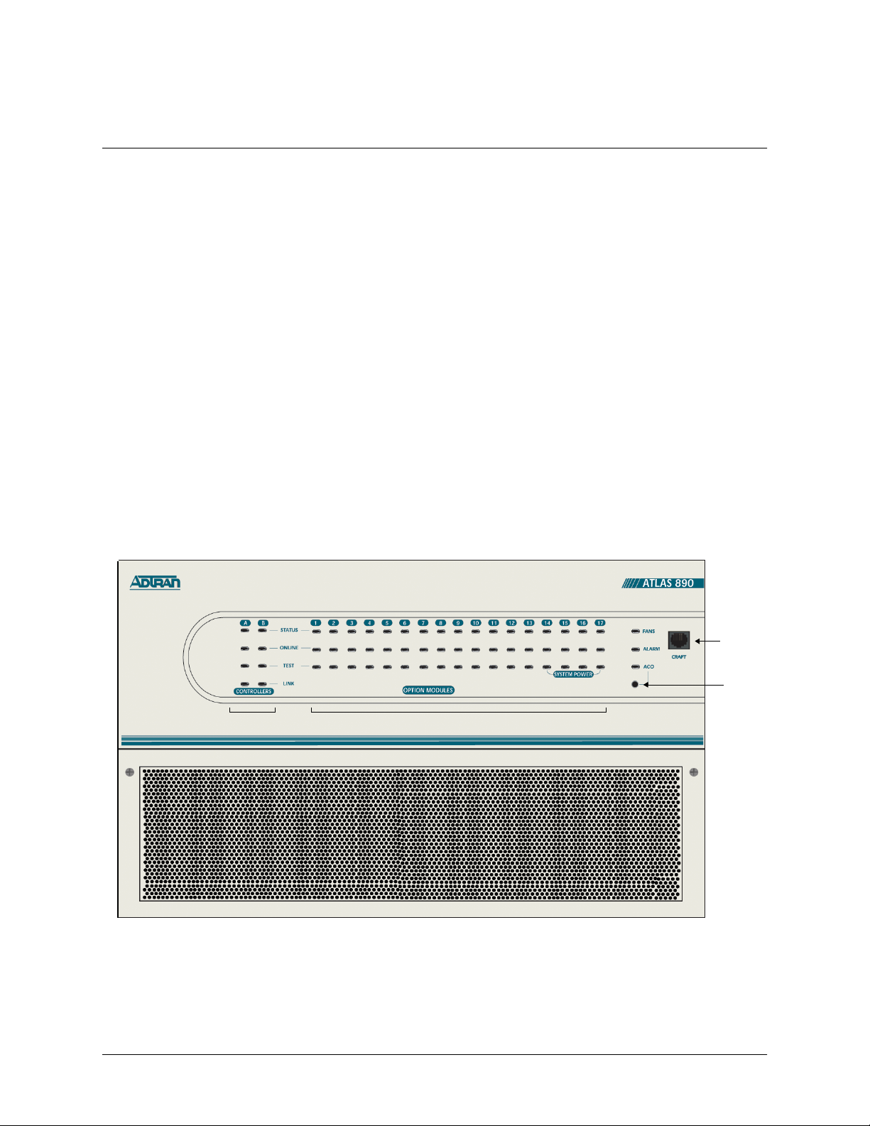
3. REVIEWING THE FRONT PANEL DESIGN
The front panel contains the Alarm Cut-off (ACO) switch, the CRAFT port, and the controller and option
module status LEDs. The LEDs provide visual information about the ATLAS 890 Base Unit and any
option module that may be installed. Figure 1 identifies the ACO switch, the CRAFT port, and the LEDs.
Controller LEDs Option Module LEDs
Figure 1. ATLAS 890 Front Panel Layout
CRAFT
Port
ACO
Switch
© 2001 ADTRAN, Inc. ATLAS 890 System Manual
Page 24

61200321L1-1A
ATLAS 890
Section 2, Engineering Guidelines
Page 4 of 22
ACO Switch
The ACO switch deactivates (clears) the Alarm Relay, located on the rear panel of the ATLAS 890, after
an alarm condition has oc curred. If an alarm condit ion is corr ected and the n reoccu rs, the Alarm Rel ay will
activate again.
CRAFT Port
Use the CRAFT port to configure the system via an EIA-232 connection. The connector type is shown
below, and Table 1 gives the CRAFT port pinout.
CONNECTOR TYPE RJ-48C
PART NUMBER AMP# 555164-2
Table 1. CRAFT Port Pinout
PIN NAME DESCRIPTION
1,2 UNUSED —
3 RXDATA Data received by the ATLAS 890
4 UNUSED —
5 TXDATA Data transmitted by the ATLAS 890
6,7 UNUSED —
8 UNUSED —
Front Panel LEDs
With the ATLAS 890 powered-up, the front panel LEDs provide visual inf ormat ion about the status of the
ATLAS 890 and any option modules that may be instal led. Table 2 provides a brief descripti on of the front
panel features, and Table 3 on page 5 provides detailed information about the LEDs.
Table 2. ATLAS 890 Front Panel Description
Feature Description
SYSTEM STATUS LEDS Displays the status of the fans, alarm, and ACO buttons for ATLAS 890.
(See Table 3 on page 5.)
Fans Indicates the fans are operatio nal .
Alarm Indicates a triggered alarm condition for the alarm relays.
ACO In dicates the alarm cut-off switch is pressed.
ATLAS 890 System Manual © 2001 ADTRAN, Inc.
Page 25

Section 2, Engineering Guidelines
Table 2. ATLAS 890 Front Panel Description (Continued)
Feature Description
61200321L1-1A
ATLAS 890
Page 5 of 22
CONTROLLER MODULE
LEDS
Displays the status of the network interface. (See Table 3.) All LEDs are
off if no network module is installed.
Status Indicates the operational condition of the controller installed in the
controller slot.
Online Indicates whether the module is available for use or is currently in use.
Test Indicates that the module is in test.
Link Indicates there is an active 10/100 Ethernet connection on the installed
controller module.
OPTION MODULE LEDS Displays by row the operational condition of each module installed in the
option slot s. (See Table 3.) All LEDs will be off if no option module is
installed.
Status Indicates the operational condition of modules installed in the option
slots.
Online Indicates whether the module is available for use or is currently in use. If
the module is manually taken offline, this LED is turned off.
Test Indicates that one or more ports within a module are in test.
ACO SWITCH Clears the Alarm Relay connection located on the rear panel of the
ATLAS 890.
CRAFT PORT Allows the ATLAS 890 to connect to a computer or modem using the
CRAFT port (an EIA-232 port).
Table 3. ATLAS 890 LEDs
FOR THESE LEDS... THIS COLOR
INDICATES THAT...
LIGHT...
FANS Red (solid) Fan speed is too low or fan is disconnected.
Amber (solid) Fan speed is too high.
Green (solid) All fans are functioning properly.
ALARM
Red (solid)
A fan, external input, or power supply error has occurred.
LED will remain red until the ACO button is pressed.
ACO Amber ACO button is being pressed.
© 2001 ADTRAN, Inc. ATLAS 890 System Manual
Page 26

61200321L1-1A
ATLAS 890
Section 2, Engineering Guidelines
Page 6 of 22
Table 3. ATLAS 890 LEDs (Continued)
FOR THESE LEDS... THIS COLOR
INDICATES THAT...
LIGHT...
STAND-BY CONTROLLER
Status Green (slow blink) Stand-by controller is present.
Online Green (solid) Stand-by controller operational for redundancy.
Red (fast blink)
Controller cannot automatically become the active
controller while the current active controller is installed.
Test N/A N/A
Link Green (solid) Ethernet link detected.
ACTIVE CONTROLLER
Status Green (slow blink) Card is not ready.
Green (fast blink) Card is not supported.
Green (solid) Active controller present.
Online Amber (solid) Controller is in test mode.
Amber (fast blink) Card is upgrading firmware.
Red (fast blink) Flash parameters are not compatible.
Green (fast blink) Card is unresponsive or not supported.
Red (fast blink) Card is not ready.
Test Amber (solid) Controller is in test mode.
Link Green (solid) Ethernet link detected.
MODULE STATUS Green (solid) Module is present.
Green (fast blink) Module has been manually taken offline by the user.
Red (solid) Module failed self-test.
Red (fast blink)
Module has no response, has been removed, or is not
supported.
Red (slow blink) Module is not ready.
None No module occupies the slot.
ATLAS 890 System Manual © 2001 ADTRAN, Inc.
Page 27

Table 3. ATLAS 890 LEDs (Continued)
61200321L1-1A
ATLAS 890
Section 2, Engineering Guidelines
Page 7 of 22
FOR THESE LEDS... THIS COLOR
LIGHT...
MODULE ONLINE Green (solid) Module has an active connection.
Green (fast blink)
MODULE TEST Yellow (solid) Module is in a test mode.
INDICATES THAT...
Module has invalid flash memory or is downloading
firmware.
4. REVIEWING THE REAR PANEL DESIGN
The ATLAS 890 rear panel contains 16 slots for housing option modules which provide a variety of additional resources an d da ta por ts. All slot s are f uncti onall y ident ical . The ATLAS 890 also contains two slots
for housing controller modules and a single slot dedicated for power supply use only (see Figure 2). The
most common configuration is a fully redundant system with two system controllers and two power supplies. A fully redundant AC-powere d ATLAS 890 provides 13 option slots. A fully redundan t DC-powered
ATLAS 890 provides 15 option slots.
Figure 2. ATLAS 890 Rear Panel
© 2001 ADTRAN, Inc. ATLAS 890 System Manual
Page 28

61200321L1-1A
ATLAS 890
Section 2, Engineering Guidelines
Page 8 of 22
Admin Port
The Admin port (EIA-232) connects to a computer or modem. The control port input provides the following functions:
• Accepts EIA-232 input from a PC or a modem for controlling the ATLAS 890.
• Operates at 2400, 9600, 19200, or 38400 bps.
• Acts as input for either VT 100 or PC control.
• Acts as an interface for flash memory software downloads using XMODEM.
The Admin connection follows, and Table 4 shows the pinout.
CONNECTOR TYPE RJ-48C
PART NUMBER AMP# 555164-2
Table 4. Admin In Pinout
PIN NAME DESCRIPTION
1 GND Ground - connected to unit chassis
2 RTS Request to send - flow control
3 RXDATA Data received by the ATLAS 890
4 DTR Data terminal ready
5 TXDATA Data transmitted by the ATLAS 890
6 CD Carrier detect
7UNUSED—
8 CTS Clear to send - flow control
10/100BaseT Connection
The 10/100BaseT port (RJ-48C) provides a 10/100BaseT Ethernet LAN connection, which is used for IP
Routing, TFTP, SNMP, and Telnet connections. The network connection follows, and Table 5 shows the
pinout.
CONNECTOR TYPE (USOC) RJ-48C
PART NUMBER AMP# 555164-2
Table 5. Ethernet Pinout
PIN NAME DESCRIPTION
1 TX1 Transmit Positive
2 TX2 Transmit Negative
3 RX1 Receive Positive
ATLAS 890 System Manual © 2001 ADTRAN, Inc.
Page 29

61200321L1-1A
ATLAS 890
Section 2, Engineering Guidelines
Page 9 of 22
Table 5. Ethernet Pinout (Continued)
PIN NAME DESCRIPTION
4, 5 UNUSED —
6 RX2 Receive Negative
7, 8 UNUSED —
Alarm Relay Connection
This connection alerts the user when a selected alarm condition exists. The four-pin, removable terminal
block connects with external wiring. Refer to DLP-002, Connecting the Alarm Contacts and the External
Input for detailed instructions. Clear the alarm condition by pressing the ACO switch located on the front
panel of the ATLAS 890.
Table 6 shows the pinout for the Alarm Relay connector.
Table 6. Alarm Relay Connector Pinout
Pin Name Description
1 Normally Closed (NC) Opens when a selected alarm condition is present.
2 Normally Open (NO) Closes when a selected alarm condition is present.
3 Common (COM)
4 Chassis Ground (GND)
Common connection between ex ternal circuitr y and NC or NO
terminal.
External Input Connection
This connection alerts the user when a selected external alarm condition exists. This connection could be
used to monitor a UPS with dry contacts or another ATLAS 890. The three-pin, removable terminal block
connects with external wiring. Refer to DLP-002, Connecting the Alarm Contacts and the External Input
for detailed instructions. Clear the alarm condition by pressing the ACO switch located on the front panel
of the ATLAS 890.
Table 7 shows the pinout for the External Input connector.
Table 7. External Relay Monitor Connector Pinout
Pin Name Description
1 INPUT Monitors for the presence or absence of -48 VDC
2 VOUT -48 VDC @ 1 mA
3 Chassis Ground (GND)
© 2001 ADTRAN, Inc. ATLAS 890 System Manual
Page 30

61200321L1-1A
ATLAS 890
Section 2, Engineering Guidelines
Page 10 of 22
5. OPTION MODULE INTERFACES Quad T1/PRI Option Module (P/N 1200185L3)
Each port of the Quad T1/PRI Option Module uses a single, eight-position modular jack to connect to the
T1 or PRI circuit. Table 8 gives the pinout for this jack.
CONNECTOR TYPE (USOC) RJ-4 8C
Table 8. T1/PRI Pinout
PIN NAME DESCRIPTION
1 R1 RXDATA-RING Receive data from the network
2 T1 RXDATA-TIP Receive data from the network
3 — UNUSED —
4 R TXDATA-RING Send data towards the network
5 T TXDATA-TIP Send data towards the network
6,7,8 — UNUSED —
Quad E1/PRA Option Module (P/N 1200264L1)
The DB-62 port of the Quad E1/PRA Option Module supplies a DB-15 connection as defined in Table 9
using provided adapter cables. The DB-62 interface pinout is shown in Table 10.
Table 9. DB-15 Connector Pinout
PIN NAME DESCRIPTION
1 RT Receive Tip
2 GND Ground
3 TT Transmit Tip
4 GND Ground
5 GND Ground
7 GND Ground
9 RR Receive Ring
11 TR Transmit Ring
ATLAS 890 System Manual © 2001 ADTRAN, Inc.
Page 31

61200321L1-1A
ATLAS 890
Section 2, Engineering Guidelines
Page 11 of 22
Table 10. DB-62 Connector Pinout
PIN NAME DESCRIPTION PIN NAME DESCRIPTION
1 P4 TT Port 4 Transmit Tip 42 GND Ground
2 P4 TR Port 4 Transmit Ring 43 P4 RT Port 4 Receive Tip
3 GND Ground 44 P4 RR Port 4 Receive Ring
6 GND Ground 45 GND Ground
7 P3 TT Port 3 Transmit Tip 48 GND Ground
8 P3 TR Port 3 Transmit Ring 49 P3 RT Port 3 Receive Tip
9 GND Ground 50 P3 RR Port 3 Receive Ring
12 GND Ground 51 GND Ground
13 P2 TT Port 2 Transmit Tip 54 GND Ground
14 P2 TR Port 2 Transmit Ring 55 P2 RT Port 2 Receive Tip
15 GND Ground 56 P2 RR Port 2 Receive Ring
18 GND Ground 57 GND Ground
19 P1 TT Port 1 Transmit Tip 60 GND Ground
20 P1 TR Port 1 Transmit Ring 61 P1 RT Port 1 Receive Tip
21 GND Ground 62 P1 RR Port 1 Receive Ring
Note: Pins that are not identified are not used.
P(1-4) indicates the Port
Quad Nx 56/64 Option Module (P/N 1200184 L 1)
Each DB-78 port of the Quad Nx 56/64 Option Module supplies a V.35 Winchester-style connection as
defined in Table 11 using provided adapter cables. The DB-78 interface pinout is shown in Table 12.
Table 11. V.35 Winchester Pinout
Pin CCITT DESCRIPTION
A 101 Protective ground (PG)
B 102 Signal ground (SG)
C 105 Request to send (RTS) from DTE
D 106 Clear to send (CTS) to DTE
E 107 Data set ready (DSR) to DTE
F 109 Received line signal detector (DCD) to DTE
H — Data terminal ready (DTR) from DTE
J — Ring indicator (RI)
© 2001 ADTRAN, Inc. ATLAS 890 System Manual
Page 32

61200321L1-1A
ATLAS 890
Section 2, Engineering Guidelines
Page 12 of 22
Table 11. V.35 Winchester Pinout (Continued)
Pin CCITT DESCRIPTION
R 104 Received data (RD-A) to DTE
T 104 Received data (RD-B) to DTE
V 115 RX clock (RC-A) to DTE
X 115 RX clock (RC-B) to DTE
P 103 Transmitted data (TD-A) from DTE
S 103 Transmitted data (TD-B) from DTE
Y 114 TX clock (TC-A) to DTE
AA 114 TX clock (TC-B) to DTE
U 113 External TX clock (ETC-A) from DTE
W 113 External TX clock (ETC-B) from DTE
NN — Test mode (TM) to DTE
Table 12. DB-78 Pinout for the Quad Nx 56/64 Option Module
PIN SIGNAL DESCRIPTION PIN SIGNAL DESCRIPTION
1 RXD-A 2/4 41 RTS-B 2/4
2RXD-B 2/4 42GND
3 RXC-A 2/4 43-48 Not used
4RXC-B 2/4 49MOD2
5TXD-A 2/4 50MOD0
6 TXD-B 2/4 51 EXT-TXC-A 1/3
7 TXC-A 2/4 52 DTR-B 1/3
8 TXC-B 2/4 53 DTR-A 1/3
9 EXT-TXC-A 2/4 54 DCD-B 1/3
10 EXT-TXC-A 2/4 55 DCD-A 1/3
11-17 Not used 56 DSR-B/RI 1/3
18 GND 57 DSR-A 1/3
19 GND 58 CTS-B 1/3
20 CHASIS GND 59 CTS-A 1/3
21 CTS-A 2/4 60 CHASIS GND
22 CST-B 2/4 61 GND
Note: 1/3 or 2/4 indicates the port on the Nx 56/64 Module
ATLAS 890 System Manual © 2001 ADTRAN, Inc.
Page 33

Section 2, Engineering Guidelines
Table 12. DB-78 Pinout for the Quad Nx 56/64 Option Module (Continued)
PIN SIGNAL DESCRIPTION PIN SIGNAL DESCRIPTION
23 DSR-A 2/4 62-68 Not used
24 DSSR-B/RI 2/4 69 MOD1
25 DCD-A 2/4 70 EXT-TXC-B 1/3
26 DCD-B 2/4 71 TXC-B 1/3
27 DTR-A 2/4 72 TXC-A 1/3
28 DTR-B 2/4 73 TXD-B 1/3
29-37 Not used 74 TXD-A 1/3
38 RTS-A 1/3 75 RXC-B 1/3
39 RTS-B 1/3 76 RXC-A 1/3
40 RTS-A 2/4 77 RXD-B 1/3
61200321L1-1A
ATLAS 890
Page 13 of 22
78 RXD-A 1/3
Note: 1/3 or 2/4 indicates the port on the Nx 56/64 Module
Quad USSI Option Module (P/N 1200261L1)
T able 13 through Ta ble 18 show pinouts for the available interfaces for th e Quad USSI Option Module and
the cable part numbers required by each interface.
Table 13. DB-78 Pinout for the Quad USSI Option Module
PIN SIGNAL DESCRIPTION PIN SIGNAL DESCRIPTION
1 RXD-A 2/4 41 RTS-B 2/4
2RXD-B 2/4 42GND
3 RXC-A 2/4 43-48 Not used
4RXC-B 2/4 49MOD2
5TXD-A 2/4 50MOD0
6 TXD-B 2/4 51 EXT-TXC-A 1/3
7 TXC-A 2/4 52 DTR-B 1/3
8 TXC-B 2/4 53 DTR-A 1/3
9 EXT-TXC-A 2/4 54 DCD-B 1/3
10 EXT-TXC-A 2/4 55 DCD-A 1/3
11-17 Not used 56 DSR-B/RI 1/3
Note: 1/3 or 2/4 indicates the port on the USSI Module
© 2001 ADTRAN, Inc. ATLAS 890 System Manual
Page 34

61200321L1-1A
ATLAS 890
Section 2, Engineering Guidelines
Page 14 of 22
Table 13. DB-78 Pinout for the Quad USSI Option Module (Continued)
PIN SIGNAL DESCRIPTION PIN SIGNAL DESCRIPTION
18 GND 57 DSR-A 1/3
19 GND 58 CTS-B 1/3
20 CHASIS GND 59 CTS-A 1/3
21 CTS-A 2/4 60 CHASIS GND
22 CST-B 2/4 61 GND
23 DSR-A 2/4 62-68 Not used
24 DSSR-B/RI 2/4 69 MOD1
25 DCD-A 2/4 70 EXT-TXC-B 1/3
26 DCD-B 2/4 71 TXC-B 1/3
27 DTR-A 2/4 72 TXC-A 1/3
28 DTR-B 2/4 73 TXD-B 1/3
29-37 Not used 74 TXD-A 1/3
38 RTS-A 1/3 75 RXC-B 1/3
39 RTS-B 1/3 76 RXC-A 1/3
40 RTS-A 2/4 77 RXD-B 1/3
78 RXD-A 1/3
Note: 1/3 or 2/4 indicates the port on the USSI Module
CONNECTOR TYPE EIA-530
SYSTEM PART NUMBER 4200261L2
Table 14. EIA-530 Connector Pinout
PIN SIGNAL DESCRIPTION PIN SIGNAL DESCRIPTION
1 Shield (Ground) 13 Clear to Send (B)
2 Transmit Data (A) 14 Transmit Data (B)
3 Received Data (A) 15 Transmit Clock (A)
4 Request to Send (A) 16 Received Data (B)
5 Clear to Send (A) 17 Receive Clock (A)
6 DCE Ready (A) 18 Local Loopback
7 Signal Ground 19 Request to Send (B)
8 Carrier Detect (A) 20 DTE Ready (A)
ATLAS 890 System Manual © 2001 ADTRAN, Inc.
Page 35

Section 2, Engineering Guidelines
Table 14. EIA-530 Connector Pinout (Continued)
PIN SIGNAL DESCRIPTION PIN SIGNAL DESCRIPTION
9 Received Clock (B) 21 Remote Loopback
10 Carrier Detect (B) 22 DCE Ready (B)
11 Ext. Transmit Clock (B) 23 DTE Ready (B)
12 Transmit Clock (B) 24 Ext. Transmit Clock (A)
25 Test Mode
CONNECTOR TYPE EIA-530A
SYSTEM PART NUMBER 4200261L2
Table 15. EIA-530A Connector Pinout
PIN SIGNAL DESCRIPTION PIN SIGNAL DESCRIPTION
1 Shield (Ground) 13 Clear to Send (B)
2 Transmit Data (A) 14 Transmit Data (B)
3 Received Data (A) 15 Transmit Clock (A)
4 Request to Send (A) 16 Received Data (B)
5 Clear to Send (A) 17 Receive Clock (A)
6 DCE Ready (A) 18 Local Loopback
7 Signal Ground 19 Request to Send (B)
8 Carrier Detect (A) 20 DTE Ready (A)
9 Received Clock (B) 21 Remote Loopback
10 Carrier Detect (B) 22 Ring Indicator
11 Ex t. Transmit Clock (B) 23 Signal Gro und
12 Transmit Clock (B) 24 Ext. Transmit Clock (A)
25 Test Mode
61200321L1-1A
ATLAS 890
Page 15 of 22
CONNECTOR TYPE RS-449/V.36
SYSTEM PART NUMBER 4200261L1
Table 16. RS-449/V.36 Connector Pinout
PIN SIGNAL DESCRIPTION PIN SIGNAL DESCRIPTION
1 Shield (Ground) 19 Signal Ground
2 Signaling Rate Indicator 20 Receive Common
3 Not Used 21 Not Used
© 2001 ADTRAN, Inc. ATLAS 890 System Manual
Page 36

61200321L1-1A
ATLAS 890
Section 2, Engineering Guidelines
Page 16 of 22
Table 16. RS-449/V.36 Connector Pinout (Continued)
PIN SIGNAL DESCRIPTION PIN SIGNAL DESCRIPTION
4 Transmit Data (A) 22 Transmit Data (B)
5 Transmit Clock (A) 23 Transmit Clock (B)
6 Rece iv ed Data (A) 24 R ec eiv e Data (B)
7 Request to Send (A) 25 Request to Send (B)
8 Receive Clock (A) 26 Receive Clock (B)
9 Clear to Send (A) 27 Clear to Send (B)
10 Local Loopback 28 Terminal in Service
11 DCE Ready (A) 29 DCE Ready (B)
12 DTE Ready (A) 30 DTE Ready (B)
13 Carrier Detect (A) 31 Carrier Detect (B)
14 Remote Loopback 32 Select Standby
15 Ring Indicator 33 Signal Quality
16 Select Frequency 34 New Signal
17 Ext. Transmit Clock (A) 35 Ext. Transmit Clock (B)
18 Test Mode 36 Standby/Indicator
37 Send Common
CONNECTOR TYPE RS-232
SYSTEM PART NUMBER 4200261L4
Table 17. RS-232 Connector Pinout
PIN SIGNAL DESCRIPTION PIN SIGNAL DESCRIPTION
1 Shield (Ground) 14 Sec. Transmit Data
2 Transmit Data 15 DCE Transmit Clock
3 Received Data 16 Sec . Receiv ed Data
4 Request to Send 17 Receive Signal Element Timing
5 Clear to Send 18 Not used
6 Data Set Ready 19 Sec. Request to Send
7 Signal Ground 20 Data Terminal Ready
8 Received Line Signal Detector 21 Signal Quality Detector
9 + Voltage 22 Ring Indicator
ATLAS 890 System Manual © 2001 ADTRAN, Inc.
Page 37

Section 2, Engineering Guidelines
Table 17. RS-232 Connector Pinout (Continued)
PIN SIGNAL DESCRIPTION PIN SIGNAL DESCRIPTION
10 - Voltage 23 Data Signal Rate Selector
11 Not used 24 DTE Transmit Clock
12 Sec. Received LIne Signal Indicator 25 Not used
13 Sec. Clear to Send
CONNECTOR TYPE CCIT X.21 V.11
SYSTEM PART NUMBER 4200261L3
Table 18. CCIT X.21 V.11 Connector Pinout
PIN SIGNAL DESCRIPTION PIN SIGNAL DESCRIPTION
1 Shield (Ground) 8 Signal Ground
61200321L1-1A
ATLAS 890
Page 17 of 22
2 Transmit Data (A) 9 Transmit Data (B)
3 Request to Send (A) 10 Request to Send (B)
4 Received Data (A) 11 Received Data (B)
5 Carrier Detect (A) 12 Carrier Detect (B)
6 Transmit/Receive Clock (A) 13 Transmit/Received Clock (B)
7 Ext. Transmit Clock (A) 14 Ext. Transmit Clock (B)
15 Not Used
Octal BRI Option Module (P/N 1200186L2)
Each port of the Octal BRI Option Module uses a single RJ-45 jack to connect to a standard BRI U interface circuit. Table 19 shows the network pinout connection. The required wiring connection follows:
CONNECTOR TYPE
PIN NAME DESCRIPTION
1, 2, 3, 6, 7, 8 Unused —
4 Ring Ring to and from the Network Interface
(USOC) RJ-45
Table 19. BRI Pinout
5 Tip Tip to and from the Network Interface
© 2001 ADTRAN, Inc. ATLAS 890 System Manual
Page 38

61200321L1-1A
ATLAS 890
Section 2, Engineering Guidelines
Page 18 of 22
Async-232 Option Module (P/N 1200182L1)
Each Async-232 Interface provides a DB-25 connection as defined in Table 20 using provided adapter
cables.
Table 20. DB-25 Connector Pinout
PIN NAME DESCRIPTION
1 Shield Shielded ground connection
2 TXD Transmit data from DTE
3 RXD Receive data to DTE
4 RTS Request to send from DTE
5 CTS Clear to send to DTE
6 DSR Data set ready to DTE
7 GND Ground
8 DCD Data carrier detect to DTE
9, 10, 11, 12, 13,
14, 15, 16, 17, 18,
19, 21, 23, 24, 25
20 DTR Data terminal ready from DTE
22 RI Ring indicator to DTE
Unused n/a
T3 Option Module (P/N 1200223L1)
Each T3 Option Module pro vides BNC conne ctors for transmit and recei ve connect ions defi ne in Table 21.
Using provided RG 59, 75 ohm cables.
Table 21. T3 Module Connections
NAME DESCRIPTION
RX IN Receive data from the network, 75 ohms ± 5%, unbalanced
TX OUT Transmit data to the network, 75 ohms ± 5%, unbalanced
ATLAS 890 System Manual © 2001 ADTRAN, Inc.
Page 39

61200321L1-1A
ATLAS 890
Section 2, Engineering Guidelines
Page 19 of 22
T3 Drop and Insert Option Module (P/N 1200225L1)
Each T3 Drop and Insert Option Module provides BNC connectors for both primary and secondary transmit and receive connections as defined in Table 22 using provided RG 59, 75 ohm cables.
Table 22. T3 Drop and Insert Module Connections
NAME DESCRIPTION
Primary RX IN Primary receive data from the network, 75 ohms ± 5%, unbalanced
Primary TX OUT Primary transmit data to the network, 75 ohms ± 5%, unbalanced
Secondary RX IN Secondary receive data from the network, 75 ohms ± 5%, unbalanced
Secondary TX OUT Secondary transmit data to the network, 75 ohms ± 5%, unbalanced
© 2001 ADTRAN, Inc. ATLAS 890 System Manual
Page 40

61200321L1-1A
ATLAS 890
Section 2, Engineering Guidelines
Page 20 of 22
6. AT-A-GLANCE SPECIFICATIONS
Table 23 lists the specifications for the ATLAS 890 system.
Table 23. Specifications
Application Feature Specification
TDM APPLICATIONS
TDM bandwidth 49 Mbps Full duplex
Dedicated map connections 766 dedicated DS0 map connections in
SWITCHING APPLICATIONS
ISDN signaling types National ISDN
each of the 5 maps
Lucent 5E
AT&T 4ESS (PRI Only)
Northern DMS-100 (Nortel Custom)
ETSI/DSS1
T1 signaling types Loop-Start
Ground-Start
E&M Wink
E&M Immediate
Feature Group D
DSP Features DTMF/MF tones support
Progress tone generation
32 available DSP channels
BRI Connections 128 connections
PRI Connections 766 DS0 connections
RBS T1 Connections 766 DS0 connections
27 simultaneous dial tones
ATLAS 890 System Manual © 2001 ADTRAN, Inc.
Page 41

Application Feature Specification
FRAME RELAY
61200321L1-1A
ATLAS 890
Section 2, Engineering Guidelines
Page 21 of 22
Table 23. Specifications (Continued)
Packet throughput 11,700 pkts/sec (64-1500 size packets)
PPP
Management signali ng
interfaces
UNI (user and network)
NNI
Management signaling types ANSI T1.617-D (Annex D)
ITU-T Q.933-A (Annex A)
LMI (Group of four)
Auto
Encapsulation RFC 1490
PVC support 990 PVCs per packet endpoint
Congestion control FECN / BECN
Discard eligible (DE)
Quality of service (QOS) Prioritization on a per-PVC basis
Testing (ADTRAN proprietary) PVC loopback
Round trip delay measurement
SNMP support RFC 1315
Connection support 35 PPP connections to the internal router
(not exceeding 11,700 packets per second)
100 PPP connections to the internal router
(requires HDLC Module and cannot exceed
11,700 packets per second)
Authentication support PAP
CHAP
EAP
Keepalive support On/Off
Interface support Numbered interfaces
Un-numbered interfaces
© 2001 ADTRAN, Inc. ATLAS 890 System Manual
Page 42

61200321L1-1A
ATLAS 890
Section 2, Engineering Guidelines
Page 22 of 22
Application Feature Specification
IP ROUTING
Route discovery RIP V1
SNMP support RFCs 1315, 1213, 1406
Table 23. Specifications (Continued)
RIP V2
ICMP
ARP
IARP
UDP Relay
OSPF
Adtran Enterprise MIB
VOICE COMPRESSION
Algorithm Voice Compression Module
G.723.1 or Netcoder (proprietary)
Number of channels supported Up to 64 compression channels
PCM coding µ-Law, A-Law (future)
Fax support 9600 bps
DTMF generation and
TIA 464A
detection
ATLAS 890 System Manual © 2001 ADTRAN, Inc.
Page 43

61200321L1-1A
ATLAS 890
Section 3, Network Turnup Procedure
Page 1 of 8
NETWORK TURNUP PROCEDURE
ONTENTS
C
Introduction . . . . . . . . . . . . . . . . . . . . . . . . . . . . . . . . . . . . . . . . . . . . . . . . . . . . . . . . . . . . . . . . . . . . . 2
Tools Required . . . . . . . . . . . . . . . . . . . . . . . . . . . . . . . . . . . . . . . . . . . . . . . . . . . . . . . . . . . . . . . . . . 2
Unpack and Inspect the SYSTEM . . . . . . . . . . . . . . . . . . . . . . . . . . . . . . . . . . . . . . . . . . . . . . . . . . . 2
Contents of ADTRAN Shipments . . . . . . . . . . . . . . . . . . . . . . . . . . . . . . . . . . . . . . . . . . . . . . . . . 2
Grounding Instructions . . . . . . . . . . . . . . . . . . . . . . . . . . . . . . . . . . . . . . . . . . . . . . . . . . . . . . . . . . . 3
Supplying Power to the Unit . . . . . . . . . . . . . . . . . . . . . . . . . . . . . . . . . . . . . . . . . . . . . . . . . . . . . . . 3
AC Powered Systems . . . . . . . . . . . . . . . . . . . . . . . . . . . . . . . . . . . . . . . . . . . . . . . . . . . . . . . . . . 3
DC Powered Systems. . . . . . . . . . . . . . . . . . . . . . . . . . . . . . . . . . . . . . . . . . . . . . . . . . . . . . . . . . 4
Mounting Options . . . . . . . . . . . . . . . . . . . . . . . . . . . . . . . . . . . . . . . . . . . . . . . . . . . . . . . . . . . . . . . . 4
Installing Network and Option Modules . . . . . . . . . . . . . . . . . . . . . . . . . . . . . . . . . . . . . . . . . . . . . .5
Instructions for Installing the ATLAS 890 Controller and Option Modules . . . . . . . . . . . . . . . . . . 5
Quad T1/PRI Option Module (P/N 1200185L3) . . . . . . . . . . . . . . . . . . . . . . . . . . . . . . . . . . . . . . 6
Quad E1/PRA Option Module (P/N 1200264L1). . . . . . . . . . . . . . . . . . . . . . . . . . . . . . . . . . . . . . 6
Quad Nx 56/64 Option Module (P/N 1200311L1) . . . . . . . . . . . . . . . . . . . . . . . . . . . . . . . . . . . . . 6
Quad USSI Option Module System (P/N 4200261LX) . . . . . . . . . . . . . . . . . . . . . . . . . . . . . . . . . 7
Octal Basic Rate ISDN Option Module (P/N 1200186L2). . . . . . . . . . . . . . . . . . . . . . . . . . . . . . . 7
T3 Option Module (P/N 1200223L1). . . . . . . . . . . . . . . . . . . . . . . . . . . . . . . . . . . . . . . . . . . . . . . 7
T3 Option Module with Drop and Insert Interface (P/N 1200225L1). . . . . . . . . . . . . . . . . . . . . . . 7
8,16,24,32 Channel Voice Compression Resource Modules (P/N 1200221LX). . . . . . . . . . . . . . 8
Nx 56/64 IMUX Resource Module (P/N 1200262L1) . . . . . . . . . . . . . . . . . . . . . . . . . . . . . . . . . . 8
HDLC Resource Module (P/N 1200222L1). . . . . . . . . . . . . . . . . . . . . . . . . . . . . . . . . . . . . . . . . . 8
Modem-16 Resource Module (P/N 1200181L1) . . . . . . . . . . . . . . . . . . . . . . . . . . . . . . . . . . . . . . 8
Async-232 Option Module (P/N 1200182L1) . . . . . . . . . . . . . . . . . . . . . . . . . . . . . . . . . . . . . . . . 8
IGURES
F
Figure 1. ATLAS 890 Slot Designation (Rear Panel) . . . . . . . . . . . . . . . . . . . . . . . . . . . . . . . . . . . 5
© 2001 ADTRAN, Inc. ATLAS 890 System Manual
Page 44

61200321L1-1A
ATLAS 890
Section 3, Network Turnup Procedure
Page 2 of 8
1. INTRODUCTION
This section discusses the installation process of the ATLAS 890 installation.
2. TOOLS REQUIRED
The tools required for installation of the ATLAS 890 shelf are:
• #2 Philli ps-head screwdriver
• Flat-head screwdriver (for installing modules)
To prevent electrical shock, do not install equipment in a wet location or during a
lightning storm.
Electronic modules can be damaged by static electrical discharge. Before handling modules, wear an antistat ic dis cha r ge wrist strap to prevent damage to electr onic c omponent s.
Place modules in anti st ati c p acking material when t ran sporting or storing. When wor king
on modules, always place them on an approved antistatic mat that is electrically
grounded.
3. UNPACK AND INSPECT THE SYSTEM
Each ATLAS 890 is shipped in its own cardboard shipping carton. Open each carton carefully and avoid
deep penetration into the carton with sharp objects.
After unpacking the unit, inspect it for possible shipping damage. If the equipment has been damaged in
transit, immediately file a claim with the carrier, then contact ADTRAN Customer Service (see Customer
Service, Product Support Information, and Training in the front of this manual).
Contents of ADTRAN Shipments
Your ADTRAN shipment includes the following items:
• The ATLAS 890 Base Unit
• The ATLAS 890 System CD
• AC Power cord - ADTRAN P/N 3127031 (with AC systems)
• 19-23” Convertable Rackmount brackets and screws
• RJ-45—DB-25 adapter (1 for modem connection)
• RJ-45 control port cable (1) - ADTRAN P/N 3127004
• RJ-45—DB-9 adapter (1)
Customers must supply the Ethernet cable.
ATLAS 890 System Manual © 2001 ADTRAN, Inc.
Page 45

61200321L1-1A
ATLAS 890
Section 3, Network Turnup Procedure
Page 3 of 8
4. GROUNDING INSTRUCTIONS
To following provides grounding instruction information from the Underwriters’ Laboratory UL1950
Standard for Safety of Information Technology Equipment Including Electrical Business Equipment, of
July 28, 1995.
An equipment grounding conductor that is not smaller in size than the ungrounded branch-circuit supply
conductors is to be installed as part of the circuit that supplies the product or system. Bare, covered, or
insulated grounding conductors are acceptable. Individually covered or insulated equipment grounding
conductors shall have a continuous outer finish that is either green, or green with one or more yellow
stripes. The equipment grounding conductor is to be connected to ground at the service equipment.
The attachment-plug receptacles in the vicinity of the product or system are all to be of a grounding type,
and the equipment grounding conductors serving these receptacles are to be connected to earth ground at
the service equipment.
A supplementary equipment grounding conductor shall be installed between the product or system and
ground that is in addition to the equipment grounding conductor in the power supply cord.
The supplementary equipment grounding conductor shall not be smaller in size than the ungrounded
branch-circuit supply conductors. The supplementary equipment grounding conductor shall be connected
to the product at the terminal provided, and shall be connected to ground in a manner that will retain the
ground connection when the product is unplugged from the receptacle. The connection to ground of the
supplementary equipment grounding conductor shall be in complian ce with the rules f or te rmin ating bonding jumpers at Part K or Article 250 of the National Electrical Code, ANSI/NFPA 70. Termination of the
supplementary equi pmen t grounding conductor is permitted to be made to buil din g steel, to a metal electrical raceway system, or to any grounded item that is permanently and reliably connected to the electrical
service equipment ground.
The supplemental ground ing conductor sha ll be connected to the equipment using a number 8 ring terminal
and should be fasten ed to the gr ound ing lu g provi ded on the r ear pa nel of the e quipment . The r ing te rminal
should be installed using the appropriate crimping tool (AMP P/N 59250 T-EAD Crimping Tool or equivalent.)
5. SUPPLYING POWER TO THE UNIT AC Powered Systems
The AC powered ATLAS 890 comes equipped with a detachable 6-foo t power cord with a 3-prong plu g for
connecting to a grounded power receptacle. As shipped, the ATLAS 890 is set to factory default conditions. After installing the Base Unit and any option modules, the ATLAS 890 is ready for power-up. To
power-up the unit , ensure that the unit is properly c onnected to an appropria te power s ource and turn on the
unit using the on/off switch on the rear panel.
© 2001 ADTRAN, Inc. ATLAS 890 System Manual
Page 46

61200321L1-1A
ATLAS 890
Section 3, Network Turnup Procedure
Page 4 of 8
• This unit shall be install ed in accordance with Article 400 and 364.8 of the NEC NFPA
70 when installed ou tside of a Re stri cted Ac cess L ocatio n (i.e ., centr al of fice, behind a
locked door, service personnel only area).
• Power to the ATLAS 890 AC system must be from a grounded 90-130 VAC, 50/60 Hz
source.
• The power receptacle uses double-pole, neutral fusing.
• Maximum recommended ambient operating temperature is 45
o
C.
DC Powered Systems
The DC powered ATLAS 890 comes equipped with a DC Power supply to furnish the voltages necessary
for proper backplane operation. As shipped, the ATLAS 890 is set to factory default conditions. After
installing the Base Unit and any option modules, the ATLAS 890 is ready for power-up.
• This unit shall be install ed in accordance with Article 400 and 364.8 of the NEC NFPA
70 when installed ou tside of a Re stri cted Ac cess L ocatio n (i.e ., centr al of fice, behind a
locked door, service personnel only area).
• Power to the ATLAS 8 90 DC syst em must be from a r eliably grounded -48 VDC sou rce
which is electrically isolated from the AC source.
• The branch circuit overcurre nt pro tec tion shall be a fuse or circuit breaker rate d min imum 60 VDC, maximum 10A.
• Maximum recommended ambient operating temperature is 45
o
C.
6. MOUNTING OPTIONS
The ATLAS 890 Base Unit may be installed for tab le top or 19- inc h or 23-inch rackmount. The ra ckmou nt
brackets included with the Base Unit can be used in 19-inch or 23-inch applications. For a rackmount
installation, the ATLAS 890 Base Unit allows flush-face mount, face-forward mount, center mount, and
rear mount.
Be careful not to upset the stability of the equipment mounting rack when installing this
product.
ATLAS 890 System Manual © 2001 ADTRAN, Inc.
Page 47

61200321L1-1A
ATLAS 890
Section 3, Network Turnup Procedure
Page 5 of 8
7. INSTALLING NETWORK AND OPTION MODULES
Figure 1 shows the option slot numbering designation as viewed from the rear of the ATLAS 890. The
functionally identical option slots only accept ATLAS 800 Series option modules and the controller slots
only accept ATLAS 890 controller modules.
Modules
Controllers
Modules or
Power Supply
Power Supply
Figure 1. ATLAS 890 Slot Designation (Rear Panel)
Option modules are intended to be serviced by qualified service personnel only.
Instructions for Installing the ATLAS 890 Controller and Option Modules
Instructions for Installing the ATLAS 890 Option Modules
Step Action
Remove the cover plate from the appropriate option slot of the ATLAS 890 rear panel.
1
Slide the Option Module into the option slot until the module is firmly seated against the front of the
2
chassis.
Secure the thumbscrews at both edges of the module. Tighten with a screwdriver.
3
Connect the cables to the associated device(s).
4
Complete installation of remaining modules and Base Unit as specified in the appropriate sections of this
5
Network Turnup Procedure.
© 2001 ADTRAN, Inc. ATLAS 890 System Manual
Page 48

61200321L1-1A
ATLAS 890
Section 3, Network Turnup Procedure
Page 6 of 8
Quad T1/PRI Option Module (P/N 1200185L3)
Shipping Contents
The ADTRAN shipment of the Quad T1/PRI Option Module includes the following items:
• Quad T1/PRI Option Module
• Quad T1/PRI Option Module Quick Start Guide
• Four cables (RJ-48C to RJ-48C), ADTRAN P/N: 3125M008
• Two crossover cable (RJ-48C to RJ-48C), ADTRAN P/N: 3125M010
• Two DB-15 to RJ-48 Adapters, ADTRAN P/N: 3196027
Quad E1/PRA Option Module (P/N 1200264L1)
Shipping Contents
The ADTRAN shipment of the Quad E1/PRA Option Module includes the following items:
• Quad E1/PRA Option Module
• Quad E1/PRA Option Module Quick Start Guide
• One DB-62 to Quad DB-15 female cable, ADTRAN P/N: 3125I061
The Quad E1/PRA Option Module may also be purchased with BNC Network Connection
Interfaces (P/N 4200264L1).
Quad Nx 56/64 Option Module (P/N 1200311L1)
Shipping Contents
The ADTRAN shipment of the Quad Nx 56/64 Option Module includes the following items:
• Quad Nx 56/64 Option Module
• Quad Nx 56/64 Option Module Quick Start Guide
• Two DB-37 to V.35 converter cables, ADTRAN P/N 3125I029
ATLAS 890 System Manual © 2001 ADTRAN, Inc.
Page 49

61200321L1-1A
ATLAS 890
Section 3, Network Turnup Procedure
Page 7 of 8
Quad USSI Option Module System (P/N 4200261LX)
Shipping Contents
The ADTRAN shipment of the Quad USSI Option Module System includes the following items:
• Quad USSI Option Module System
• Quad USSI Option Module System Quick Start Guide
And one of the following:
• EIA-530/530A to DB-78 Cable (System P/N 4200261L2, Cable P/N 3125I058)
• RS-449/V.36 (System P/N 4200261L1, Cable P/N 3125I057)
• RS-232 (System P/N 4200261L4, Cable P/N 3125I063)
• CCIT X.21 V.11 (System P/N 4200261L3, Cable P/N 3125I056)
Octal Basic Rate ISDN Option Module (P/N 1200186L2)
Shipping Contents
The ADTRAN shipment of the Octal Basic Rate ISDN Option Module includes the following items:
• Octal Basic Rate ISDN Option Module
• Octal Basic Rate ISDN Option Module Quick Start Guide
• Eight RJ-45-to-RJ-11 cables, ADTRAN P/N: 3125M007
T3 Option Module (P/N 1200223L1)
Shipping Contents
The ADTRAN shipment of the T3 Option Module includes the following items:
• T3 Option Module
• T3 Option Module Quick Start Guide
• Two 6 ft. coaxial BNC cables (ADTRAN P/N 3125I054)
T3 Option Module with Drop and Insert Interface (P/N 1200225L1)
Shipping Contents
The ADTRAN shipment of the T3 Option Module with Drop and Insert Interface includes the following
items:
• T3 Option Module with Drop and Insert Interface
• T3 Option Module with Drop and Insert Interface Quick Start Guide
• Four 6 ft. coaxial BNC cables (ADTRAN P/N 3125I054)
© 2001 ADTRAN, Inc. ATLAS 890 System Manual
Page 50

61200321L1-1A
ATLAS 890
Section 3, Network Turnup Procedure
Page 8 of 8
8,16,24,32 Channel Voice Compression Resource Modules (P/N 1200221LX)
Shipping Contents
The ADTRAN shipment of the 8,16,24,32 Channel Voice Compression Resource Modules includes the
following items:
• 8,16,24,32 Channel Voice Compression Resource Modules
• 8,16,24,32 Channel Voice Compression Resource Modules Quick Start Guide
Nx 56/64 IMUX Resource Module (P/N 1200262L1)
Shipping Contents
The ADTRAN shipment of the Nx 56/64 IMUX Resource Module includes the following items:
• Nx 56/64 IMUX Resource Module
• Nx 56/64 IMUX Resource Module Quick Start Guide
HDLC Resource Module (P/N 1200222L1)
Shipping Contents
The ADTRAN shipment of the HDLC Resource Module includes the following items:
• HDLC Resource Module
• HDLC Resource Module Quick Start Guide
Modem-16 Resource Module (P/N 1200181L1)
Shipping Contents
The ADTRAN shipment of the Modem-16 Resource Module includes the following items:
• Modem-16 Resource Module
• Modem-16 Resource Module Quick Start Guide
Async-232 Option Module (P/N 1200182L1)
Shipping Contents
The ADTRAN shipment of the Async-232 Option Module includes the following items:
• Async-232 Option Module
• Async-232 Option Module Quick Start Guide
• Two DB-78 to Octal RS-232 cables (ADTRAN P/N 3125I030)
ATLAS 890 System Manual © 2001 ADTRAN, Inc.
Page 51

61200321L1-1A
ATLAS 890
Section 4, User Interface Guide
Page 1 of 234
USER INTERFACE GUIDE
This section of ADTRAN’s ATLAS 890 System Manual is designed for use by network administrators and
others who will configure and provision the system. It contains information about navigating the VT-100
user interface and using the four-character display.
ONTENTS
C
Navigating the Terminal Menu . . . . . . . . . . . . . . . . . . . . . . . . . . . . . . . . . . . . . . . . . . . . . . . . . . . . . 3
Terminal Menu Window . . . . . . . . . . . . . . . . . . . . . . . . . . . . . . . . . . . . . . . . . . . . . . . . . . . . . . . . 3
Menu Path . . . . . . . . . . . . . . . . . . . . . . . . . . . . . . . . . . . . . . . . . . . . . . . . . . . . . . . . . . . . . . . 3
Window Panes . . . . . . . . . . . . . . . . . . . . . . . . . . . . . . . . . . . . . . . . . . . . . . . . . . . . . . . . . . . . 3
Additional Terminal Menu Window Features . . . . . . . . . . . . . . . . . . . . . . . . . . . . . . . . . . . . . 5
Navigating Using the Keyboard Keys . . . . . . . . . . . . . . . . . . . . . . . . . . . . . . . . . . . . . . . . . . . . . . 5
Moving through the Menus . . . . . . . . . . . . . . . . . . . . . . . . . . . . . . . . . . . . . . . . . . . . . . . . . . . 5
Session Management Keystrokes . . . . . . . . . . . . . . . . . . . . . . . . . . . . . . . . . . . . . . . . . . . . . 6
Configuration Keystrokes . . . . . . . . . . . . . . . . . . . . . . . . . . . . . . . . . . . . . . . . . . . . . . . . . . . . 7
Getting Help . . . . . . . . . . . . . . . . . . . . . . . . . . . . . . . . . . . . . . . . . . . . . . . . . . . . . . . . . . . . . . 7
Terminal Menu and System Control . . . . . . . . . . . . . . . . . . . . . . . . . . . . . . . . . . . . . . . . . . . . . . . . . 8
Selecting the Appropriate Menu . . . . . . . . . . . . . . . . . . . . . . . . . . . . . . . . . . . . . . . . . . . . . . . . . . 8
Security Levels . . . . . . . . . . . . . . . . . . . . . . . . . . . . . . . . . . . . . . . . . . . . . . . . . . . . . . . . . . . . . . . 8
Menu Descriptions . . . . . . . . . . . . . . . . . . . . . . . . . . . . . . . . . . . . . . . . . . . . . . . . . . . . . . . . . . . . . . . 9
System Info . . . . . . . . . . . . . . . . . . . . . . . . . . . . . . . . . . . . . . . . . . . . . . . . . . . . . . . . . . . . . . . . . . 9
System Status . . . . . . . . . . . . . . . . . . . . . . . . . . . . . . . . . . . . . . . . . . . . . . . . . . . . . . . . . . . . . . . 11
System Config . . . . . . . . . . . . . . . . . . . . . . . . . . . . . . . . . . . . . . . . . . . . . . . . . . . . . . . . . . . . . . . 17
System Utility . . . . . . . . . . . . . . . . . . . . . . . . . . . . . . . . . . . . . . . . . . . . . . . . . . . . . . . . . . . . . . . . 27
Modules . . . . . . . . . . . . . . . . . . . . . . . . . . . . . . . . . . . . . . . . . . . . . . . . . . . . . . . . . . . . . . . . . . . . 37
Modules Menu (Quad T1/PRI Option Module) . . . . . . . . . . . . . . . . . . . . . . . . . . . . . . . . . . . . . . . 39
Modules Menu (Quad E1/PRA Option Module) . . . . . . . . . . . . . . . . . . . . . . . . . . . . . . . . . . . . . . 46
Modules Menu (Quad Nx 56/64 Option Module) . . . . . . . . . . . . . . . . . . . . . . . . . . . . . . . . . . . . . 51
Modules Menu (Quad USSI Option Module) . . . . . . . . . . . . . . . . . . . . . . . . . . . . . . . . . . . . . . . . 58
Modules Menu (IMUX 56/64 Resource Module) . . . . . . . . . . . . . . . . . . . . . . . . . . . . . . . . . . . . . 65
Modules Menu (Octal BRI Option Module) . . . . . . . . . . . . . . . . . . . . . . . . . . . . . . . . . . . . . . . . . 68
Modules Menu (Voice Compression Resource Module) . . . . . . . . . . . . . . . . . . . . . . . . . . . . . . . 70
Modules Menu (Async-232 Option Module) . . . . . . . . . . . . . . . . . . . . . . . . . . . . . . . . . . . . . . . . . 77
Modules Menu (Modem-16 Option Module) . . . . . . . . . . . . . . . . . . . . . . . . . . . . . . . . . . . . . . . . . 86
Modules Menu (HDLC Option Module) . . . . . . . . . . . . . . . . . . . . . . . . . . . . . . . . . . . . . . . . . . . . 98
Modules Menu (T3 Option Module) . . . . . . . . . . . . . . . . . . . . . . . . . . . . . . . . . . . . . . . . . . . . . . . 99
Modules Menu (T3 with Drop and Insert Option Module) . . . . . . . . . . . . . . . . . . . . . . . . . . . . . 109
Packet Manager . . . . . . . . . . . . . . . . . . . . . . . . . . . . . . . . . . . . . . . . . . . . . . . . . . . . . . . . . . . . . 119
Router . . . . . . . . . . . . . . . . . . . . . . . . . . . . . . . . . . . . . . . . . . . . . . . . . . . . . . . . . . . . . . . . . . . . 142
Dedicated maps . . . . . . . . . . . . . . . . . . . . . . . . . . . . . . . . . . . . . . . . . . . . . . . . . . . . . . . . . . . . . 167
Dedicated Maps - (Quad T1/PRI Option Module) . . . . . . . . . . . . . . . . . . . . . . . . . . . . . . . . . . . 170
Dedicated Maps - (Quad E1/PRA Option Module) . . . . . . . . . . . . . . . . . . . . . . . . . . . . . . . . . . . 172
Dedicated Maps - (Quad Nx 56/64 Option Module) . . . . . . . . . . . . . . . . . . . . . . . . . . . . . . . . . . 173
© 2001 ADTRAN, Inc. ATLAS 890 System Manual
Page 52

61200321L1-1A
ATLAS 890
Section 4, User Interface Guide
Page 2 of 234
Dedicated Maps - (Quad USSI Option Module) . . . . . . . . . . . . . . . . . . . . . . . . . . . . . . . . . . . . . 173
Dedicated Maps - (Octal BRI Option Module) . . . . . . . . . . . . . . . . . . . . . . . . . . . . . . . . . . . . . . 174
Dedicated Maps - (T3 and T3 with Drop and Insert Option Modules) . . . . . . . . . . . . . . . . . . . . 174
Dedicated Maps - (Pkt Endpt Connections) . . . . . . . . . . . . . . . . . . . . . . . . . . . . . . . . . . . . . . . . 176
Dedicated Maps - (Packet Voice Connections) . . . . . . . . . . . . . . . . . . . . . . . . . . . . . . . . . . . . . 177
Circuit Status . . . . . . . . . . . . . . . . . . . . . . . . . . . . . . . . . . . . . . . . . . . . . . . . . . . . . . . . . . . . . . . 178
Dial Plan . . . . . . . . . . . . . . . . . . . . . . . . . . . . . . . . . . . . . . . . . . . . . . . . . . . . . . . . . . . . . . . . . . . 181
Dial Plan - (Quad T1/PRI, T3, and T3 Drop and Insert Option Modules) . . . . . . . . . . . . . . . . . . 193
Dial Plan - (Quad E1/PRA Option Module) . . . . . . . . . . . . . . . . . . . . . . . . . . . . . . . . . . . . . . . . 214
Dial Plan - (Quad Nx 56/64 Option Module) . . . . . . . . . . . . . . . . . . . . . . . . . . . . . . . . . . . . . . . . 219
Dial Plan - (Quad USSI Option Module) . . . . . . . . . . . . . . . . . . . . . . . . . . . . . . . . . . . . . . . . . . . 220
Dial Plan - (Octal BRI/U Option Module) . . . . . . . . . . . . . . . . . . . . . . . . . . . . . . . . . . . . . . . . . . 222
Dial Plan - (Async-232 Option Module) . . . . . . . . . . . . . . . . . . . . . . . . . . . . . . . . . . . . . . . . . . . 225
Dial Plan - (Pkt Endpt Connections) . . . . . . . . . . . . . . . . . . . . . . . . . . . . . . . . . . . . . . . . . . . . . . 226
Dial Plan - (Circuit Backup Connections) . . . . . . . . . . . . . . . . . . . . . . . . . . . . . . . . . . . . . . . . . . 228
Dial Plan - (Packet Voice Connections) . . . . . . . . . . . . . . . . . . . . . . . . . . . . . . . . . . . . . . . . . . . 231
IGURES
F
Figure 1. Top-Level Terminal Menu Window . . . . . . . . . . . . . . . . . . . . . . . . . . . . . . . . . . . . . . . . . 3
Figure 2. Alternate Menu View . . . . . . . . . . . . . . . . . . . . . . . . . . . . . . . . . . . . . . . . . . . . . . . . . . . . 4
Figure 3. System Information Menu . . . . . . . . . . . . . . . . . . . . . . . . . . . . . . . . . . . . . . . . . . . . . . . . 9
Figure 4. System Status Menu . . . . . . . . . . . . . . . . . . . . . . . . . . . . . . . . . . . . . . . . . . . . . . . . . . . 11
Figure 5. System Configuration Menu. . . . . . . . . . . . . . . . . . . . . . . . . . . . . . . . . . . . . . . . . . . . . . 17
Figure 6. System Utility Menu . . . . . . . . . . . . . . . . . . . . . . . . . . . . . . . . . . . . . . . . . . . . . . . . . . . . 27
Figure 7. View Selftest Log . . . . . . . . . . . . . . . . . . . . . . . . . . . . . . . . . . . . . . . . . . . . . . . . . . . . . . 32
Figure 8. ATLAS 890 System Controller Self-Test Log. . . . . . . . . . . . . . . . . . . . . . . . . . . . . . . . . 33
Figure 9. Modules Menu . . . . . . . . . . . . . . . . . . . . . . . . . . . . . . . . . . . . . . . . . . . . . . . . . . . . . . . . 37
Figure 10. Loopback Test Diagram. . . . . . . . . . . . . . . . . . . . . . . . . . . . . . . . . . . . . . . . . . . . . . . . . 44
Figure 11. E1/PRA Network Loopback Tests . . . . . . . . . . . . . . . . . . . . . . . . . . . . . . . . . . . . . . . . . 50
Figure 12. Network Loopback Tests . . . . . . . . . . . . . . . . . . . . . . . . . . . . . . . . . . . . . . . . . . . . . . . 108
Figure 13. Packet Manager Menu. . . . . . . . . . . . . . . . . . . . . . . . . . . . . . . . . . . . . . . . . . . . . . . . . 119
Figure 14. Router Menu (IP Selected). . . . . . . . . . . . . . . . . . . . . . . . . . . . . . . . . . . . . . . . . . . . . . 142
Figure 15. Dedicated Maps Menu . . . . . . . . . . . . . . . . . . . . . . . . . . . . . . . . . . . . . . . . . . . . . . . . . 167
Figure 16. Circuit Status Menu . . . . . . . . . . . . . . . . . . . . . . . . . . . . . . . . . . . . . . . . . . . . . . . . . . . 178
Figure 17. Dial Plan Menu. . . . . . . . . . . . . . . . . . . . . . . . . . . . . . . . . . . . . . . . . . . . . . . . . . . . . . . 181
ABLES
T
Table 1. Password Security Level . . . . . . . . . . . . . . . . . . . . . . . . . . . . . . . . . . . . . . . . . . . . . . . . . . 8
Table 2. IP Statistics . . . . . . . . . . . . . . . . . . . . . . . . . . . . . . . . . . . . . . . . . . . . . . . . . . . . . . . . . . 154
Table 3. ICMP Statistics . . . . . . . . . . . . . . . . . . . . . . . . . . . . . . . . . . . . . . . . . . . . . . . . . . . . . . . 156
Table 4. TCP Statistics . . . . . . . . . . . . . . . . . . . . . . . . . . . . . . . . . . . . . . . . . . . . . . . . . . . . . . . . 157
Table 5. UDP Statistics . . . . . . . . . . . . . . . . . . . . . . . . . . . . . . . . . . . . . . . . . . . . . . . . . . . . . . . . 158
Table 6. IP Fast Cache Statistics . . . . . . . . . . . . . . . . . . . . . . . . . . . . . . . . . . . . . . . . . . . . . . . .159
ATLAS 890 System Manual © 2001 ADTRAN, Inc.
Page 53

61200321L1-1A
ATLAS 890
Section 4, User Interface Guide
Page 3 of 234
1. NAVIGATING THE TERMINAL MENU Terminal Menu Window
The ATLAS 890 uses a multi-level men u stru cture that conta ins bot h menu i tems a nd data fiel ds. All menu
items and data fields display in the terminal menu window (see Figure 1), through which you have complete control of the ATLAS 890.
Menu Path
Left Pane
Right Pane
SCU
^A=more
Extended Help
Slot Status
Tool Tip
Navigation He lp
System Time
Figure 1. Top-Level Terminal Menu Window
Menu Path
The first line of the terminal menu window (the menu path) shows the session’s current position (path) in
the menu structure. For example, Figure 1 shows the top-level menu with the cursor on the
submenu; therefore, the menu path reads
Window Panes
ATLAS 890/System Info
.
YSTEM INFO
S
When you first start a terminal menu session, the terminal menu window is divided into left and right
panes. The left pane shows the list of available submenus, while the right pane shows the contents of the
currently selected submenu.
You can view the terminal windows in two ways: with fields and submenus displaying horizontally across
the right pane, or with fields and submenus displaying vertically down the right pane. Viewing submenus
vertically rather than horizontally allows you to see information at a glance rather than scrolling horizontally across the window. To change the view, move your cursor to an index number and press <Enter>.
© 2001 ADTRAN, Inc. ATLAS 890 System Manual
Page 54

61200321L1-1A
ATLAS 890
Section 4, User Interface Guide
Page 4 of 234
Figure 2 shows this alternate view. Fields and submenu names may vary slightly in this view.
Figure 2. Alternate Menu View
Window Pane Navigation
Use the following chart to assist you in moving between and within the two window panes.
To do this... Press this key...
Move from left pane to right pane Tab
Enter
Right arrow
Move from right pane to left pane Tab
Escape
Left arrow
Backspace
Move within each pane Up arrow
Down arrow
Left arrow
Right arrow
Right Window Pane Notation
The right window pane shows the contents of the currently selected menu. These contents can
include both submenu items and data fields. Some submenus contain additional submenus and
ATLAS 890 System Manual © 2001 ADTRAN, Inc.
Page 55

61200321L1-1A
ATLAS 890
Section 4, User Interface Guide
Page 5 of 234
some data fields contain additional data fields. The following chart explains the notation used to
identify these additional items.
This notation... Means that...
[+] More items are available when selected
[DATA] More items are available when selected
<+> An action is to be taken, such as activating a test
Highlighted menu item You can enter data in this field
Underlined field The field contains read-only information
Additional Terminal Menu Window Features
• SCU - displays stat us i nformat ion a bout t he sy stem c ontrol lers , such as ONLI N (onl ine), STBY (st andby), and NRDY (not ready).
• Tool Tip - provides a brief description of the currently selected (highlighted) command
• Slot Status - displays status information, such as OK, WARN, or ALRM about slots 1-16
• Extended Help - displays information about selected commands (
CTRL+A
)
• Navigation Help - lists characters used for navigating the terminal menu and session management
CTRL+Z
(
)
• System Time - displays current time
Navigating Using the Keyboard Keys
You can use various keystrokes to move through the terminal menu, to manage a terminal menu session,
and to configure the system. Press <CTRL+Z> to activate a pop-up screen listing the navigation keystrokes.
Moving through the Menus
To do this... Press this key...
Return to the home screen H
Jump between two menu items
Press <J> while the cursor is locate d on a me nu it em, and you jump bac k to the
main screen.
Go to another menu item, press <J>, and you jump back to the screen that was
displayed the first time you pressed <J>.
Press <J> anytime you want to jump between these items.
© 2001 ADTRAN, Inc. ATLAS 890 System Manual
J
Page 56

61200321L1-1A
ATLAS 890
Section 4, User Interface Guide
Page 6 of 234
To do this... Press this key...
Select items Arrows
Edit a selected menu item Enter
Cancel an e dit Escape
Close pop-up help screen Escape
Move between the left and right panes Tab
Arrows
Move to the top of a screen A
Move to the bottom of a screen Z
Ascend one menu level Backspace
Session Management Keystrokes
To do this... Press this key...
Log out of a session CTRL+L
Invalidate the password entry and return to the login screen CTRL+S
Refresh the screen
To save time, only the portion of the screen that has changed is refreshed. This
CTRL+R
option should only be necessary if the display picks up incorrect characters
caused by disconnecting and reconnecting the terminal session.
View Extended Data
CTRL+V
Display data fields too large for display window.
ATLAS 890 System Manual © 2001 ADTRAN, Inc.
Page 57

61200321L1-1A
ATLAS 890
Section 4, User Interface Guide
Page 7 of 234
Configuration Keystrokes
To do this... Press this key...
Restore factory default settings.
This setting restores the factory defaults based on the location of the cursor. If the
cursor is on a module line (in the
ODULES
M
menu), then only the selected module
is updated to factory defaults.
Copy selected items to the clipboard.
The amount of informa ti on yo u ca n copy depends on the cur so r l oca ti on whe n you
press <C>:
If the cursor is over an editable field, only tha t item is copied.
If the cursor is over the index number of a list, then all of the items in the row of
LOT
the list are co pied. For example, if the cursor is over the
ODULES
M
screen, all of the information associated with the slot is copied.
S
field in the
#
Paste the item stored in the clipboard, if the information is compatible.
You must confirm all pastes - except those to a single editable field.
Increment the value of certain types of fields by one when you paste information
into those fields.
Decrement the value of certain types of fields by one when you paste information
into those fields.
Insert a new list item.
For examp le, add a new item to the
EDICATED MAP
D
connection list by pressing
<I> while the cursor is over the index number.
F
C
P
>
<
I
Delete a list item.
For example, delete an item from the
while the index number is active.
<D>
Getting Help
EDICATED MAP
D
connection list by pres si ng
D
The bottom line of the terminal menu window contains context-sensitive help information. When the cursor is positioned over a set of configuration items, a help message displays (when available) providing a
description of the item. When more detailed help is ava ilable for a pa rticular item, ^A displays at the bottom of the window. At this point, if you press <CTRL+A>, a pop-up h elp sc reen di splay s with inf ormati on
about the item.
Press <CTRL+Z> to activate a help screen that displays the available keystrokes you can use to navigate
the terminal menu.
© 2001 ADTRAN, Inc. ATLAS 890 System Manual
Page 58

61200321L1-1A
ATLAS 890
Section 4, User Interface Guide
Page 8 of 234
2. TERMINAL MENU AND SYSTEM CONTROL Selecting the Appropriate Menu
The terminal menu is the access point to all other operations. Each terminal menu item has several functions and submenus that identify and provide access to specific operations and parameters. Use the chart
below to help select the appropriate terminal menu.
To do this... Go to this menu...
Review and monitor general system information for the ATLAS 890
Review and monitor sy stem status for the ATLAS 890
Set up the operational configuration for the ATLAS 890
Update settings, transfer files, perform system diagnostics, and reboot
the ATLAS 890
Review and configure settings for each installed module, including the
ATLAS 890 network modules
Define and configure all layer 2 connect ions i ncludi ng Frame Rel ay and
PPP endpoints
Define, configure and monitor all ATLAS 890 Router functions
Assign dedicated connections between any two ports in the ATLAS 890
Dial Backup functions including monitoring the status of backup links,
manually forcing a backup switch, and restoring a primary connection
Set global ATLAS 890 switch parameters or set individual parameters
for each port in the ATLAS 890 that handles a switched call
YSTEM INFO
S
YSTEM STATUS
S
YSTEM CONFIG
S
YSTEM UTILITY
S
ODULES
M
ACKET MANAGER
P
OUTER
R
EDICATED MAPS
D
IRCUIT STATUS
C
IAL PLAN
D
Security Levels
To edit terminal menu items, you must have a password and the appropriate security level. Table 1
describes the six security levels.
Table 1. Password Security Level
Security Level Descript ion
5 Read-only permission for all menu items 4 Read permission for all menu items and permission to use test commands
3
ATLAS 890 System Manual © 2001 ADTRAN, Inc.
Access to all commands except passwords, flash download, authentication
methods, and interface configurations
minimum rights
Page 59

Table 1. Password Security Level (Continued)
Security Level Descript ion
61200321L1-1A
ATLAS 890
Section 4, User Interface Guide
Page 9 of 234
2
Access to all commands except passwords, flash download, and authentication
methods
1 Access to all commands except passwords
0
Permission to edit every menu item, including creating and editing passwords -
maximum rights
3. MENU DESCRIPTIONS
The remainder of this section describes ATLAS 890 menu and submenu options.
To help you follow the terminal menu hierarchy, the following notations are used:
ENUS
>
M
UBMENUS
» S
»» SUB-
SUBMENUS
> SYSTEM INFO
YSTEM INFO
The
S
mation. Figure 3 displays the submenus and data fields that are available when you select this menu item.
menu provides basic information about the unit as well as data fields for editing infor-
Figure 3. System Information Menu
© 2001 ADTRAN, Inc. ATLAS 890 System Manual
Page 60

61200321L1-1A
ATLAS 890
Section 4, User Interface Guide
Page 10 of 234
YSTEM NAME
»S
Write security: 3; Read se curity: 5
Provides a user-configurable text string for the name of the ATLAS 890. This name can help you distinguish between different installations. You can enter up to 40 alphanumeric characters in this field,
including spaces and special characters (such as an underbar).
YSTEM LOCATION
»S
Write security: 3; Read se curity: 5
Provides a user-configurable text string for the location of the ATLAS 890. This field is to help you
keep track of the physical location of the unit. You can enter up to 40 alphanumeric characters in this
field, incl uding spaces and special characters (such as an underbar).
YSTEM CONTACT
»S
Write security: 3; Read se curity: 5
Provides a user-configurable text string for a contact name. You can use this field to enter the name,
phone number , o r e -mai l a ddr ess of a per son responsible for the ATLAS 890 system. You can enter up
to 40 alphanumeric cha r acters in this field, incl uding spaces and special characters (such as an underbar).
IRMWARE REVISION
»F
Read security: 5
Displays the current firmware revision level of the control ler.
YSTEM UPTIME
»S
Read security: 5
Displays the length of time the ATLAS 890 system has been running. Each time you reset the system,
this value resets to 0 days, 0 hours, 0 min and 0 secs.
TARTUP MODE
»S
Read security: 5
Displays details about the last system startup. For example, rebooting the ATLAS 890 from the
TEM UTILITY
URRENT TIME/DATE
»C
menu will cause this field to read
(24HR)
ARM REBOOT
W
.
Write security: 3; Read se curity: 5
Displays the current date and time, including seconds. To edit this field, place the cursor on the field
and press <Enter>. Then, enter the time in a 24-hour format (such as 23:00:00 for 11:00 pm), and the
date in mm-dd-yyyy format (for example, 10-30-1998). Press <Enter> when you are finished to exit
the menu item.
NSTALLED MEMORY
»I
Read security: 5
Displays the type and amount of memory in use (including Flash memory and DRAM).
YS
S
-
ATLAS 890 System Manual © 2001 ADTRAN, Inc.
Page 61

61200321L1-1A
Section 4, User Interface Guide
Page 11 of 234
ERIAL NUMBER
»S
Read security: 5
Displays the serial number for the unit. The serial number of the ATLAS 890 will automatically display in this field.
ATLAS 890
OOT
»B
ROM R
EV
Read security: 5
Displays the boot ROM revision.
> SYSTEM STATUS
YSTEM STATUS
The
S
parameters inclu ding l ogge d syst em event s and t iming. Figure 4 disp lays t he subme nus and dat a fie lds t hat
are availab le when you select this menu item.
menu provides the user with status information about the ATLAS 890 operational
Figure 4. System Status Menu
VENT LOG
»E
Read security: 5
Displays the last 349 warning or failure messages sent including the day, date, and priority of the message. The most recent messages display at the top of the list. The following read-only fields are available to review:
»» T
IME
Displays the date (mm/dd) and the time (hh:mm:ss) that the event
occurred.
© 2001 ADTRAN, Inc. ATLAS 890 System Manual
Page 62

61200321L1-1A
ATLAS 890
Section 4, User Interface Guide
Page 12 of 234
»» C
AT
Displays the severity of the event. The possible categories are
Critical, Major, Minor, Warning, Normal, and Info. You can specify
which types of errors you want the system to log with the System
Event Logging option. See Section 7, System Event Logging for
details.
»» S
»» S
RC
LOT
Displays the source of the event.
Displays the slot number in which the event occurred. If this field
displays SCUA or SCUB (for the active system controller), the event
that occurred was an ATLAS 890 system event.
ORT
»» P
VENT DESCRIPTION
»» E
LEAR SYSTEM EVENT LOG
»C
Displays the port in which the event occurred.
Displays a description of the event.
Write security: 3; Read se curity: 3
Clears the event log. When you select this command, the following prompt displays:
Confirm (y/n)
This will clear the entire event log.
Select
Y
to clear the log or N to exit the c ommand.
If you clear the event log, you cannot retrieve the data.
THERNET PORT
»E
Read security: 5
Displays status information about the Ethernet port. An a st eri sk (*) indicates ac ti vi ty for the item. The
following read-only fie lds are available to review:
»» I /F S
X FRAMES
»» T
TATUS
Indicates the current status of the Ethernet port.
Indicates the number of frames transmitted from the Ethernet port
since system startup.
»» R
X FRAMES
Indicates the number of frames received on the Ethernet port since
system startup.
THERNET RATE
»» E
ATLAS 890 System Manual © 2001 ADTRAN, Inc.
Indicates whether the Ethernet network is 10 or 100BaseT.
Page 63

DMIN PORT
»A
Write security: 2; Read se curity: 5
Displays the status of the RJ-45 Admin port.
61200321L1-1A
ATLAS 890
Section 4, User Interface Guide
Page 13 of 234
IGNAL LEADS
»» S
Displays the state of the Admin port signals (
DTR
X BYTES
»» T
X BYTES
»» R
VERRUN ERRS
»» O
RAMING ERRS
»» F
LEAR COUNTERS
»» C
Displays the number of bytes transmitted from the Admin port.
Displays th e number of bytes received by the Admin port.
Displays the number of overrun errors received by the Admin port.
Displays th e number of f raming errors received by the Admin port.
Write security: 5; Read secu rity: 5
Clears the Admin port statistics. Press Y to activate this command.
RAFT PORT
»C
Write security: 2; Read se curity: 5
Displays the status of the RJ-45 Craft port.
X BYTES
»» T
X BYTES
»» R
VERRUN ERRS
»» O
RAMING ERRS
»» F
Displays the number of bytes transm itted from the Craft port .
Displays the number of bytes received by the Craft port.
Displays the number of overrun er rors receiv ed by the Craft port.
Displays the number of framing errors received by the Craft port.
RTS, CTS, DCD
, and
).
LEAR COUNTERS
»» C
Write security: 5; Read secu rity: 5
Clears the Craft port statistics. Pre ss Y to activate this command .
YSTEM ALARMS
»S
Read security: 5
Contains alarm infor mation for t he ATLAS 890 system including power, temperature, fan and external
input alarms.The following status symbols are used:
[–]
[*]
[!]
OWER ALARMS
»» P
Normal condition
Failure condition
No Informat ion Available
Read security: 5
Indicates that one or both of the power supplies are not functional. These power supplies are
continuously monitored to determine failures. If one of these supplies fails, a message will be
placed in the
© 2001 ADTRAN, Inc. ATLAS 890 System Manual
VENT LOG
E
(see Section 7, System Event Logging for more details).
Page 64

61200321L1-1A
ATLAS 890
Section 4, User Interface Guide
Page 14 of 234
EMPERATURE ALARMS
»» T
Read security: 5
Indicates that the in ternal temper ature of th e power s upply ha s excee ded normal o perat ing limits. When the operating temperat ure is exceeded by any power supply in slots 14-17, a warn ing
will be placed in the
no other action will be taken.
AN ALARMS
»» F
Indicates that installed fans are operating normally.
XTERNAL INPUT ALARMS
»» E
Indicates that the external input has been activated.
VENT LOG
E
(see Section 7, Syste m Event Loggi ng for more details), but
[–]
[*]
YSTEM TIMING SOURCE
»S
Indicates input is not active
Indicates input is active
Read security: 5
Indicates which ti ming source ( primary or ba ckup) is cu rrently b eing used by ATLAS 890 and whether
the system is locked onto thi s sou rc e. If the disp la y does not indicate locked, the ATLAS 890 does not
have a valid source of timing and cannot reliably transfer data. Review the current setting for system
timing source in the
YSTEM CONFIG
S
menu. See Primary Timing Source and Backup Timing Source
on page 17 for details.
ESOURCE USAGE
»R
Write security: 5; Read se curity: 5
Provides resource usage tracking for dynamic resources throughout the system. This includes current,
average, and minimum availability for both analog and digital resources.
ATA TABLES
»» D
Read security: 5
Displays resource usage for dynamic resources throughout the system in a table format.
ESOURCE TYPE
R
Displays types of dynamically allocated resources being tracked
throughout the system. Examples are
resource),
IGITAL
D
(digital call resource), and
NALOG
A
(analog modem
KT VOICE
P
voice compression resource).
(packet
URRENT
C
Shows the number of resources available (not in use) and the total
number of resources. I f a resourc e is taken of fl ine, it is no t include d
in the total.
VERAGE
A
Shows the average number of resources available since the
statistics were last reset .
IN
M
ATLAS 890 System Manual © 2001 ADTRAN, Inc.
Shows the fewest numbe r of resources avail able since the last reset.
Page 65

61200321L1-1A
ATLAS 890
Section 4, User Interface Guide
Page 15 of 234
0 (
ZERO
) A
VAIL
Provides a count of the number of times the quantity of available
resources reached 0.
R DATA
H
Displays the
VERAGE
A
down in hour increments for a 24-hour period.
ESET
R
Write security: 4; Read security: 5
Activates the reset of all accumulated availability statistics for the
selected resource.
ONFIG
»» C
Write security: 3; Read se curity: 5
Configures the statistics displayed under data tables.
ISPLAY FORMAT
D
Read security: 5
Sets the display format for all
either raw data or percentages.
ESET MODE
R
Write security: 3; Read security: 5
Sets the reset mode for the
the followin g:
AILY
- performs reset daily at 12:00 AM
D
EEKLY
W
ANUAL
M
- performs reset on Saturday night, 12:00 AM
- disables aut omatic reset of th e res ourc e usag e stat isti cs
INIMUM
,
M
ESOURCE USAGE
R
ESOURCE USAGE
R
, and
VAILABLE
0 A
data broken
statistics to
statistics to one of
RUNK USAGE
»T
Write security: 5; Read se curity: 5
Indicates trunk use: (
ATA TABLES
»» D
ET TERM
N
Read security: 5
Display for collected resource usage data.
RUNK TYPE
T
URRENT
C
VERAGE
A
IN
M
ZERO
0 (
Shows the number of resources available (not in use) and the total
VAIL
) A
PRI, NET T
ERM
RBS; U
SER TERM
PRI, U
SER TERM
RBS
).
Displays types of trunks in the system.
number of resources . If a re source is taken of fli ne, it is not incl uded
in the total.
Shows the average number of resources available since the
statistics were last reset .
Shows the fewest number of resources available since the last reset.
Provides a count of the number of times the quantity of available
resources reached 0.
© 2001 ADTRAN, Inc. ATLAS 890 System Manual
Page 66

61200321L1-1A
ATLAS 890
Section 4, User Interface Guide
Page 16 of 234
LT/PRT
S
ESET
R
ONFIG
»» C
Write security: 5; Read security: 5
Configures the statistics displayed under data tables.
ISPLAY FORMAT
D
ESET MODE
R
EDUNDANCY
»R
Write security: 5; Read se curity: 5
Displays the usage data broken down by slots and ports.
Write security:
4; Read security: 5
Activates the reset of all accumulated availability statistics.
Write security:
Sets the display format for all
5; Read security: 5
ESOURCE USAGE
R
statistics to
either raw data or percentages.
Write security:
Sets the reset mode for the
3; Read security: 5
ESOURCE USAGE
R
statistics to one of
the followin g:
AILY
- performs reset daily at 12:00 AM
D
EEKLY
W
ANUAL
M
- performs reset on Saturday night, 12:00 AM
- disables automatic reset of the resource usage
statistics
»» SCU A
Read security: 5
Displays the current status of the controller module installed in the controller A slot.
»» SCU B
Read security: 5
Displays the current status of the controller module installed in the controller B slot.
ARDWARE COMPATIBILITY
»» H
Read security: 5
Displays the current hardware of the controller modules installed in the controller A and controller B slots. Provides status for any compatibility issues that exist.
IRMWARE COMPATIBILITY
»» F
Read security: 5
Indicates whether the firmware revision of cont roller A and c ontroller B have any incompatibility problems that would affect controller switchover.
CTIVE/STANDBY CONFIGURATION
»» A
Read security: 5
Compares the configurati on of cont roll er A and cont roll er B and di splays any discr epanci es in
the comparison and indicates when the controllers are synchronized.
ATLAS 890 System Manual © 2001 ADTRAN, Inc.
Page 67

TANDBY STARTUP MODE
»» S
Read security: 5
Displays the manner in which the standby controller booted.
NTERCONTROLLER COMMUNICATIONS
»» I
Read security: 5
Displays the status of the Intercontroller Communications Channel (ICC).
> SYSTEM CONFIG
YSTEM CONFIG
The
S
shows the items included in this menu.
menu allows you to set up the ATLAS 890 operational configuration. Figure 5
61200321L1-1A
ATLAS 890
Section 4, User Interface Guide
Page 17 of 234
Figure 5. System Configuration Menu
RIMARY TIMING SOURCE
»P
Write security: 1; Read se curity: 5
Selects the primary timing source. You can select either
NTERNAL
I
or any port from one of the
installed network or option modules.
ACKUP TIMING SOURCE
»B
Write security: 1; Read se curity: 5
Selects the secondary timing source. You can select either
NTERNAL
I
or any port from one of the
installed network or option modules. ATLAS 890 uses the backup timing source if the primary timing
source goe s into alarm. The
OURCE
S
© 2001 ADTRAN, Inc. ATLAS 890 System Manual
for the most reliable operation.
ACKUP TIMING SOURCE
B
should be different from the
RIMARY TIMING
P
Page 68

61200321L1-1A
ATLAS 890
Section 4, User Interface Guide
Page 18 of 234
» ADLP A
DDRESS
Write security: 2; Read se curity: 5
Shows the system ADTRAN Data Link Layer Protocol (ADLP) addres s for co nnecting remot e devices
to ADTRAN management software. The allowable range is between 2 and 65520. Enter a value not
used by any other ADTRAN units controlled by the management software.
ESSION TIMEOUT
»S
Write security: 3; Read se curity: 5
Defines the number of seconds the terminal session must remain idle before the session times out. You
can enter zero to deactivate this option (the session will never time out).
AX TELNET SESSIONS
»M
Write security: 3; Read se curity: 5
Defines the maximum number of Telnet sessions that can be active at the same time. Enter a number
between 0 and 12 in this field.
If you enter zer o in this field , you wil l not be able to us e Telnet. Only enter zero if you want
to completely lock out Telnet access.
THERNET PORT
»E
Write security: 2; Read se curity: 5
Provides a way to configure various settings for the Ethernet port. The following options are availabl e
for review and editing:
»» P
ORT NAME
Defines the name of the Ethernet port. You can leave this field
blank.
»» IP A
DDRESS
Lists the address as signed to the ba se Ethe rnet p ort. Thi s addr ess i s
composed of four decimal numbers, each in the range of 0 to 255,
separated by periods. T his value is set to 0.0.0.0 by default. The IP
address is used for the 10/100BaseT Ethernet interface. Obtain the
correct IP address from your LAN administrator.
EFAULT GATEWAY
»» D
Defines or changes the d efault gateway. Enter the d efault gateway
address by enteri ng a decimal nu mber into the appropriate field and
then pressing <Enter> to move to the next field. You will need a
default gateway if the LAN contains multiple segments. This
address is compose d of f our dec imal numbers, each in th e r ange of
0 to 255, separated by periods. This value is set to 0.0.0.0 by
default. Contact your LAN administrator for the appropriate
address.
ATLAS 890 System Manual © 2001 ADTRAN, Inc.
Page 69

61200321L1-1A
ATLAS 890
Section 4, User Interface Guide
Page 19 of 234
UBNET MASK
»» S
Defines which part of a desti nation IP addre ss contains the network
number. This address is composed of four decimal numbers, each
in the range of 0 to 255, separated by periods. This value is set to
0.0.0.0 by default. This part of the destination IP address is used
along with the ATLAS 890 IP address to determine which nodes
must be reached through the default IP gateway.
»» MAC A
DDRESS
Displays the system Ethernet Media Access Control (MAC)
address. This field is re ad-only.
THERNET SPEED
»» E
Defines the rate at which the ethernet port operates. Choose from
10 M
the ATLAS 890 auto detects th e data rat e of the L AN and sets i tself
to that rate, either 10 or 100 Mbps.
DMIN PORT
»A
Write security: 2; Read se curity: 5
Accepts input for configuring the Admin port.
»» P
ORT NAME
Defines the name of the Admin port. You can leave this field
blank.
»» P
ORT TYPE
Specifies whether you use
used when connecting to a VT-100 terminal, and
used for modem access.
BPS
or
A
UTO
10/100
. When the unit is set for
IRECT
D
or
D
IAL
mode.
D
IAL
D
UTO
A
IRECT
mode is
10/100
mode is
,
ORT SPEED
»» P
ODEM INITIALIZATION
»» M
TRING
S
Specifies the baud r ate of the p ort. Sele ct eithe r 2400, 9600, 19200,
or 38400. If you are using
ORT SPEED
P
Specifies the initialization string for a modem. Refer to your
setting matches the modem baud rate.
IAL
D
for
ORT TYPE
P
, ensure that the
modem documentation for acceptab le ini ti al iz at ion stri ngs . The
default value will set most modems to the appropriate
configuration for the ATLAS 890.
NITIALIZE MODEM
»» I
Write security:
Read security:
4;
5
Sends the modem initialization string to the modem. When you
Please verify
or
H/W
LOW CONTROL
»» F
select this command, the following message displays:
a modem is connected to the Admin port before continuing. Confirm
(y/n).
Ensure that a modem is connected before selecting Y.
This option sets the flow control for the Admin port. You may
configure the Admin port flow control for
N
ONE
(hardware).
© 2001 ADTRAN, Inc. ATLAS 890 System Manual
Page 70

61200321L1-1A
ATLAS 890
Section 4, User Interface Guide
Page 20 of 234
RAFT PORT
»C
Write security: 2; Read se curity: 5
»» P
»» P
ORT NAME
ORT SPEED
Defines the name of the Craft port. You can leave this field blank.
Specifies the baud r ate of the p ort. Sele ct eithe r 2400, 9600, 19200,
or 38400. If you are using
ORT SPEED
P
setting matches the modem baud rate.
IAL
D
for
ORT TYPE
P
, ensure that the
» SNMP
Write security: 3; Read se curity: 5
Provides a way to configur e S NMP access for the ATLAS 890. The following opti ons ar e avai labl e for
review and editing:
»» SNMP A
CCESS
Write security: 3; Read Security: 5
Defines whether SNMP access to the ATLAS 890 is enabled or disabled. Select the appropriate option.
»» SNMP C
OMMUNITIES
Write security: 3; Read Security: 5
Defines SNMP manager(s) characteristics as follows:
P ADDRESS
I
RIVILEGES
P
Specifies the IP address of the network manager.
Defines the
ET
(read-only) and
G
ET/SET
G
(read and write)
privileges.
G
S
RAP TRANSMISSION
»» T
ET NAME
ET NAME
Defines the community name for
match the
UBLIC
P
ET
name defined on the net work manag ement stat ion.
G
is the default name.
Defines the community name for
match either the
G
ET
management station.
or
UBLIC
P
ET
S
ET
access. This value must
G
ET
access. This value must
S
name defined on the network
is the default name.
Write security: 3; Read Security: 5
Enables and disables SNMP trap transmission.
UTHEN TRAP TRANSMISSION
»» A
Write security: 3; Read Security: 5
Enables and disables the authentication failure trap.
ATLAS 890 System Manual © 2001 ADTRAN, Inc.
Page 71

RAPS DESTINATION
»» T
Write security: 3; Read Security: 5
Defines the destination for SNMP traps as follows:
61200321L1-1A
ATLAS 890
Section 4, User Interface Guide
Page 21 of 234
P ADDRESS
I
Identifie s the IP addres s for the network manager (NM) to sends
traps.
OMMUNITY
C
Defines the community name for trap destinations. This name
must match the community name defined on the NM.
RAP
T
ILTERING
F
Sets the minimum severity level required for a system event to
generate an SNMP trap. If a trap event occurs with a security
level equal to or more severe than the trap ty pe’ s curre nt threshold
setting, the event is se nt as an SNMP trap. (Ref er to the ADTRAN
T echni cal Sup port web p age (www.adtran.com) for a listing of all
MIBs containing traps and their security levels.) The following
ISABLED
D
ORMAL
N
N
, and
OMMUNITY NAME
C
ORMAL
. If you are
as
T-W
with
,
NFO
I
ATCH
TATION
S
YPE
T
threshold levels for the available selections:
RITICAL
C
To deliver the SNMP tr ap packet with the
unchanged, define the
using T-Watch PRO, define the
GMT
M
AJOR
,
M
,
M
and append the
INOR
S
C
ARNING
,
W
TATION TYPE
TATION TYPE
S
OMMUNITY NAME
,
as
“.ADLP ADDRESS.” Within the SNMP trap packet, this field is
automatically updated before it is sent to the management station.
»» DS1 C
URRENT PERF THRESHOLDS
Write security: 3; Read Security: 5
Defines performance thre shold values for DS1 Line and Path statis tics recorde d in a 15-minute
interval. If a statis tic value exceeds its th res hol d val ue, then the correspondin g Aler t Trap will
be sent if the alert event is armed and Alert Traps are enabled. These thresholds apply to all
DS1 interfaces in the sy stem.
.
URRENT
C
HRSH
T
ES
The DS1 performance monitor Threshold Value for the Current
15 minute Errored Seconds (ES) parameter. The default value is
65 for an approximate BER level of 10E-5.
URRENT
C
SES T
HRSH
The DS1 performance monitor Threshold Value for the Current
15 minute Severely Errored Seconds (SES) parameter. The
default value is 10 for an approximate BER level of 10E-5.
URRENT
C
SEFS
HRSH
T
© 2001 ADTRAN, Inc. ATLAS 890 System Manual
The DS1 performance monitor Threshold Value for the Current
15 minute Severely Errored Framing Seconds (SEFS) parameter.
The default value is 2 for an approximate BER level of 10E-5.
Page 72

61200321L1-1A
ATLAS 890
Section 4, User Interface Guide
Page 22 of 234
URRENT
C
UAS T
URRENT
C
CSS T
URRENT
C
PCV T
(D4)
URRENT
C
PCV T
(ESF)
URRENT
C
LES T
URRENT
C
LCV T
HRSH
HRSH
HRSH
HRSH
HRSH
HRSH
The DS1 per formance mon itor Threshold Value for the Current
15 minute Unavailable Seconds (UAS) parameter. The default
value is 10 for an approximate BER level of 10E-5.
The DS1 per formance mon itor Threshold Value for the Current
15 minute Controlled Slip Seconds (CSS) parameter. The default
value is 1 for an approximate BER level of 10E-5.
The DS1 per formance mon itor Threshold Value for the Current
15 minute Path Code Violations (PCV) parameter, when the Line
Type is Super Frame (AT&T D4 format) DS1. The default value
is 72 framing errors for an approximate BER level of
10E-5.
The DS1 per formance mon itor Threshold Value for the Current
15 minute Path Code Violations (PCV) parameter, when the Line
Type is Extended Super Frame DS1. The default value is 13,296
CRC errors for an approximate BER level of 10E-5.
The DS1 per formance mon itor Threshold Value for the Current
15 minute Line Errored Seconds (LES) parameter. The default
value is 65 for an approximate BER level of 10E-5.
The DS1 per formance mon itor Threshold Value for the Current
15 minute Line Code Violations (LCV) parameter. The default
value is 13,340 for an approximate BER level of 10E-5.
»» DS1 T
OTAL CURRENT PERF THRESHOLDS
Write security: 3; Read Security: 5
Defines pe rformance threshold values for DS1 Line and Path statisti cs. If a statistic value
exceeds its threshold value, then the corresponding Alert Trap will be sent if the alert event is
armed and Alert T r aps are en abl ed. The se thresholds apply to all DS1 int er fa ces in the system.
OTAL
T
ES
THRSH
The DS1 performance monitor Threshold Value for the Total
Errored Seconds (ES) parameter. The default value is 648 for an
approximate BER level of 10E-5.
OTAL
T
SES T
HRSH
The DS1 performance monitor Threshold Value for the Total
Severely Errored Seconds (SES) parameter. The default value is
100 for an approximate BER level of 10E-5.
OTAL
T
SEFS
HRSH
T
ATLAS 890 System Manual © 2001 ADTRAN, Inc.
The DS1 performance monitor Threshold Value for the Total
Severely Errored Framing Seconds (SEFS) parameter. The
default value is 17 for an approximate BER level of 10E-5.
Page 73

61200321L1-1A
ATLAS 890
Section 4, User Interface Guide
Page 23 of 234
OTAL
T
UAS T
OTAL
T
CSS T
OTAL
T
PCV T
(D4)
OTAL
T
PCV T
(ESF)
OTAL
T
LES T
OTAL
T
LCV T
HRSH
HRSH
HRSH
HRSH
HRSH
HRSH
The DS1 performance monitor Threshold Value for the Total
Unavailable Seconds (UAS) parameter. The default value is 10
for an approximate BER level of 10E-5.
The DS1 performance monitor Threshold Value for the Total
Controlled Slip Seconds (CSS) parameter. The default value is 4
for an approximate BER level of 10E-5.
The DS1 performance monitor Threshol d Value for the Total Pat h
Code Violations (PCV) parameter, when the Line Type is Super
Frame (AT&T D4 format) DS1. The default value is 691 framing
errors for an approximate BER level of 10E-5.
The DS1 performance monitor Threshol d Value for the Total Pat h
Code Violations (PCV) parameter, when the Line Type is
Extended Super Frame DS1. The default value is 132,960 CRC
errors for an approximate BER level of 10E-5.
The DS1 performance monitor Threshold Value for the Total
Line Errored Seconds (LES) parameter. The default value is 648
for an approximate BER level of 10E-5.
The DS1 performance monitor Threshold Value for the Total
Line Code Violations (LCV) parameter. The default value is
133,400 for an approximate BER level of 10E-5.
»» ASP E
NDPOINT COMMUNITIES
Write security: 0; Read se curity: 0
Configures the ADLP list used when accepting incoming traps from remote ADTRAN TSU
100 Series or ISU 512 units. For a trap to be recognized and sent to the network management
station, the remote unit must be listed in the ASP Endpoint Communities list. The following
parameters must be configured:
ADLP
DDRESS
A
ADLP
ASSWORD
P
Enter the ADLP address (Unit ID) of the remote unit. Only traps
containing an ADLP address listed here will be accepted.
Enter the ADLP password (Unit Password) of th e remote uni t.
The password will be verified before traps will be accepted from
the remote unit.
»» SNMP/ASP P
ROXY
Write security: 0; Read se curity: 0
Enables or disables Get_Request capabilities for remote units. When enabled, this feature
allows SNMP requests to be sent from the Network Management Station through the ATLAS
890 to the selected remote unit. Remote units must be ADTRAN TSU 100 Series or ISU 512
products.
© 2001 ADTRAN, Inc. ATLAS 890 System Manual
Page 74

61200321L1-1A
ATLAS 890
Section 4, User Interface Guide
Page 24 of 234
»» SNMP/ASP P
OLLING
Write security: 0; Read se curity: 0
Enables or disables tr ap polling through the ATLAS 890 to remote ADTRAN TSU 100 Series
or ISU 512 units. When enabled, this feature allows the ATLAS 890 to forward any traps
received from remote units to the Network Management Station. The remote unit must be
listed in the ASP Endpoint Communities for the traps to be forwarded.
VENT LOGGING
»E
Write security: 3; Read se curity: 5
Sets the system event severity level threshold for each of the ATLAS 890 system event types. Whenever a system event occurs, that event is logged if the event’s severity level is equal to or more severe
than the event type’s current threshold setting. See Section 7, System Event Logging for detailed information on the system events.
YSLOG SETUP
»S
Write security: 3; Read se curity: 3
Configures the ATLAS 890 Syslog client for use with a Syslog server (supplied with ADTRAN Utilities or available on most UNIX plat forms).
RANSMISSION
»» T
Write security: 3; Read se curity: 3
Enables or disables the transmission of log events to the external Syslog server
»» H
OST
IP A
DDRESS
Write security: 3; Read se curity: 3
Lists the IP address of the external server that is running the Syslog host daemon.
OST FACILITY
»» H
Write security: 3; Read se curity: 3
Specifies the facility destination of log events. Facilities are located on the host and are managed by the Syslog host daemon running on either a UNIX machine or a PC.
EAL TIME CLOCK
»R
Write security: 3; Read se curity: 5
Provides access to the two options listed below. You can review and edit these options.
»» C
URRENT
IME/DATE
T
Displays the current date and time, including seconds. To edit this
field, enter the time in 24-hour format (such as 23:00:00 for 11:00
pm), and enter the date in mm-dd-yyyy format (for example,
09-23-1998).
UTO DAYLIGHT
»» A
AVINGS
S
When enabled, automatically updates the time and date when
Daylight Savings Time starts and when Standard Time ends.
ATLAS 890 System Manual © 2001 ADTRAN, Inc.
Page 75

61200321L1-1A
ATLAS 890
Section 4, User Interface Guide
Page 25 of 234
CCESS PASSWORDS
»A
Write security: 0; Read se curity: 0
Provides a way to e dit p asswords and to ad d new user s and pas swords. All menu items ar e protec ted by
passwords of varying secu ri ty le vel s. By assi gning different pas swor ds to different security levels, the
ATLAS 890 system administrator can control which users can change various menu items. You can
assign multiple passwords at the same access level. This way, different users with the same access
privileges can have different passwords. Each of the six password security levels are described in
Table 1 on page 8.
»» L
»» P
ABEL
ASSWORD
Defines a username.
Allows you to change the password (the default password is
password
). The current password displays as a series of asterisks
(********). The password can contain up to a combination of 12
case-sensitive alphanumeric characters, spaces, or special characters.
CCESS RIGHTS
»» A
Defines the password level for the correspon ding label. You can select
from six different password levels (see Table 1 on page 8).
»» A
CTIVE
Displays the number of users for each label that are currently logged
into the system.
ONDING CONFIG
»B
Write security: 3; Read se curity: 5
Displays the configuration submenus available for the IMUX Module. This configuration is shared amo ng all
IMUX Modules
»» TXI N IT T
.
IMER
Specifies the le ngth o f ti me the or igin ating endpoi nt at tempts to detec t
the BONDING negotiation pattern from the answering endpoint
before deciding the BONDING call has failed.
»» TXFA T
IMER
Specifies the length of time both endpoints attempt to detect the
BONDING frame pattern when a call i s connected bef ore decid ing the
BONDING call has failed. When interoperating with other
manufacturers' BONDING equipment, it may be necessary to change
this time so that it matches
TXADD01
.
»» TXADD01 T
IMER
Specifies the length of time both endpoints wait for additional calls to
be connected at the end of negotiation before deciding that the
BONDING call has failed. The factory default setting is sufficient for
most calls to connect, although when dialing overseas it may be
necessary to lengthen this timer to allow for slower call routing.
»» TXDEQ T
IMER
Specifies the length of time both endpoints attempt to equalize the
network delay between the bearer channels before deciding the
BONDING call has failed.
© 2001 ADTRAN, Inc. ATLAS 890 System Manual
Page 76

61200321L1-1A
ATLAS 890
Section 4, User Interface Guide
Page 26 of 234
»» TANULL T
»» TCID T
»» C
IMER
ALL STAGGER
IMER
Specifies the length of time the answering endpoint attempts to detect
the BONDING negotiation pattern from the originating endpoint
before deciding the BONDING call has failed. It may be necessary to
shorten this timer if t he DTE equipment using the BONDING mo dul e
also has timer constraints for completing non-BONDING parameter
negotiation.
Specifies the length of time both endpoints attempt to negotiate an
agreeable value for bearer channels and channel capacities before
deciding the BONDING call has failed.
Specifies the amount of delay between placing calls for outgoing
BONDING sessions. Th e following call stagger values are av ailable
O STAGGER
N
There is no delay between the call dialing of a BONDING session.
MS
500
Wait approximately ½ second between the call dialing of a
BONDING session.
SEC
1
.
Wait approximately 1 second between the call dial ing of a BONDING
session.
SEC
.
2
Wait approximately 2 seconds between the call dialing of a
BONDING session.
LARM RELAY RESET
»A
Write security: 3; Read se curity: 5
Clears the Alarm Relay located on the rear panel of the ATLAS 890. Activating the software Alarm
Relay Reset functions th e same as man ually pres sing the ACO Swit ch located on the ATLAS 890 front
panel.
LARM RELAY THRESHOLD
»A
Write security: 3; Read se curity: 5
Defines which threshold sets the Alarm Relay. These thresholds include
ARNING
W
, and
Alarm Relay will set. For example, if the threshold is set for
ORMAL
N
. If an alarm occurs that is greater than or equal to the threshold selected, the
AJOR
M
RITICAL
C
, then ALL Major alarms and ALL
critical alarms wil l set the Al arm Relay. There is one exception -- sett ing the thr eshold to
,
M
AJOR
N
,
M
ORMAL
not set the Alarm Relay for Normal events. No Normal events set the Alarm Relay.
XTERNAL INPUT THRESHOLD
»E
Write security: 3; Read se curity: 5
Defines the alarm level and text for external swit ch contacts. If the external switch contact is closed,
the alarm is thrown and t he event text is sent to the event log.
INOR
will
,
ATLAS 890 System Manual © 2001 ADTRAN, Inc.
Page 77

AME
»» N
Read security: 5
Displays the name External Input to identify the entry for the external input alarm.
ESCRIPTION
»» D
Write security: 3; Read se curity: 5
Contains the user-defi ned te xt that will be sent to the ATLAS 890 event log when the alarm is
triggered.
EVEL
»» L
Write security: 3; Read se curity: 5
Defines th e event log category for th e message associated wi th the alarm. For more details on
event log categories, refer to Section 7, System Event Logging.
> SYSTEM UTILITY
Use the
YSTEM UTILITY
S
Section 4, User Interface Guide
menu to view and set the system parameters shown in Figure 6.
61200321L1-1A
ATLAS 890
Page 27 of 234
Figure 6. System Utility Menu
PDATE FIRMWARE
»U
Write security: 1; Read se curity: 5
Updates firmware when ATLAS 890 enhancements are released. Two transfer methods are available
for use in updating any modules that contain Flash memory—including the ATLAS 890 system controller. The first transfer method uses the ATLAS 890 serial Admin port of the system controller and
© 2001 ADTRAN, Inc. ATLAS 890 System Manual
Page 78

61200321L1-1A
ATLAS 890
Section 4, User Interface Guide
Page 28 of 234
XMODEM protocol. The second transfer method uses the ATLAS 890 built-in Ethernet port of the
system controller and Trivial File Transfer Protocol (TFTP). For more details on updating firmware,
please refer to DLP-009 and DLP-010.
ODULE SLOT
»» M
Write security: 1; Read se curity: 5
Displays the slot you selected for firmware updating. When this option first appears,
ELECTED
S
opens, allowing you to select
OF A TYPE
ODULE TYPE
»» M
displays. When you move the cursor to this field and press <Enter>, a dialog box
SCU A, SCU B, S
LOT
through
1
S
LOT
16, or
LL MODULES
A
.
Write security: 1; Read se curity: 5
Reflects the module type selected in
ODULE SLOT
M
. The selections only include upgradable
modules.
RANSFER METHOD
»» T
Write security: 1; Read se curity: 5
Lists the two transf er met hods for updat ing fi rmware a fter sele cting a module slo t:
and
TFTP. XMODEM
ports XMODEM uploads to the terminal interface.
transfers files by connecting to a communications program that sup-
transfers files by specifying an
TFTP
XMODEM
appropriate server address and filename. The standby controller may only be upgraded using
the ICC channel.
FTP SERVER
T
IP A
DDRESS
Write security: 1; Read security: 5
Configures the IP address of the TFTP Server on which the update file resides.
ATLAS 890 uses this field to lo cate the network server o n which the u pdate file
resides.
N
ONE
FTP SERVER FILENAME
T
Write security: 1; Read security: 5
Identifies the name of the update file to retrieve from the TFTP Server. Enter the full
path name and filename for the file.
ESTART SCHEDULE
»» R
Write security: 1; Read se curity: 5
Indicates when to restart the updat ed module to invoke the new code, aft er sel ec ti ng a modul e
slot. The two options include
PECIFIED DATE AND TIME
S
ESTART IMMEDIATELY AFTER UPDATE
R
ESTART IMMEDIATELY AFTER UPDATE
R
.
and
ESTART AT
R
Write security: 1; Read security: 5
Automatically restarts the module immediately after the update is complete.
ATLAS 890 System Manual © 2001 ADTRAN, Inc.
Page 79

61200321L1-1A
Section 4, User Interface Guide
Page 29 of 234
ESTART AT SPECIFIED DATE AND TIME
R
Write security: 1; Read security: 5
Lets you specify a date and time to automatically restart the updated module. When
you select this option, a new field called
ESTART DATE AND TIME
R
displays below
the current field.
ESTART DATE AND TIME
R
Write security: 1; Read security: 5
Defines the date and time to re start the system after updating. Ente r the time using
a 24-hour format (i.e., 23: 25:30 for 11PM, 25 minutes, 30 seconds). Enter the dat e
in mm-dd-yyyy format (i.e.,11-08-2000).
URRENT UPDATE STATUS
»» C
Read security: 5
Indicates progress or problems encountered during the current update process. The field dis-
DLE
plays
of a successful update, the contents of this field are copied into
if no update is in progress or when the updat e is successf ully completed. At the end
I
REVIOUS UPDATE STATUS
P
ATLAS 890
.
If you are updating several modules at the same time (if
ULES OF A TYPE
), this option displays [+], indicating this field contains submenu items. The
ODULE SLOT
M
is set to
LL MOD
A
following submenus display:
LT
S
YPE
T
URRENT STATUS
C
REVIOUS STATUS
P
REVIOUS TIME
P
During the TFTP upload process, various status messages are provided in the
PDATE STATUS
U
REVIOUS UPDATE STATUS
»» P
field. For a detailed listing of these messages, please refer to DLP-010.
Indicates the slot number.
Defines the type of module for each slot.
Indicates the status of the current update.
Indicates the status of the previous update.
Indicates the time of the previous update.
URRENT
C
Read security: 5
Displays the status of the previous update, after selecting a module slot. If a firmware update
has not bee n attempted for a particu l ar slot, this field reads
lowing a successful update, the field reads
ODULE UPDATE COMPLETE
M
AS NOT BEEN ATTEMPTED
H
. If an update was
unsuccessful, the appropriate error message displays.
EGIN FIRMWARE UPDATE
»» B
Write security: 1; Read se curity: 5
Begins updating th e fir mware for the s elect ed mo dules. To start this action, ente r Y to begin or
enter N to cancel. You can also cancel the operation after the update has begun. For
XMODEM updates, cancel the proces s via the term inal emulatio n software (consult your
documentation for the information on how to do this). For TFTP updates, you can cancel the
process by selecting
ANCEL UPDATE
C
from this field.
-
. Fol-
© 2001 ADTRAN, Inc. ATLAS 890 System Manual
Page 80

61200321L1-1A
ATLAS 890
Section 4, User Interface Guide
Page 30 of 234
PDATE STATUS
»U
Read security: 5
Displays the status of the cu rr ent fir mware update. These fields are id ent ic al to thos e def ined above in
URRENT UPDATE STATUS
C
ONFIG TRANSFER
»C
.
Write security: 3; Read se curity: 5
Used only with TFTP transfers. Sends a file containing the ATLAS 890 configuration to a file on a
TFTP server using the TFTP protocol through the 10/100BaseT Ethernet port.
ONFIG TRANSFER
C
also lets you save the ATLAS 890 configuration as a backup file, so you can use the same configuration with mu ltiple ATLAS 890 units. In addition,
ONFIG TRANSFER
C
can retrieve a configuration file
from a TFTP server.
To support these transfers, ADTRAN delivers a TFTP program with ATLAS 890 called TFTP Server.
You can configure any PC running Microsoft Windows with this software, and store a configuration
file.
Only one configuration transfer session (upload or download) can be active at a time. The TCP/IP
parameters are not saved or overwritten as part of an ATLAS 890 unit’s transferred configuration;
therefore, identical configurations can be sent to multiple units. For complete details on configuration
transfers to/from the ATLAS 890, please refer to DLP-010.
RANSFER METHOD
»» T
Write security: 3; Read se curity: 5
Displays the method used to transfer the configuration file to or from a server. Currently,
TFTP is required.
»» TFTP S
ERVER
IP A
DDRESS
Write security: 3; Read se curity: 5
Specifies the IP address of the TFTP server. Get this address information from your System
Administrator.
»» TFTP S
ERVER FILENAME
Write security: 3; Read se curity: 5
Defines the name of the configuration file that you transfer to or retrieve from the TFTP
server. The default name is
URRENT TRANSFER STATUS
»» C
ATLAS890.cfg
, but it is editable.
Read security: 5
Indicates t he current sta t us of the upd ate.
REVIOUS TRANSFER STATUS
»» P
Read security: 5
Indicates the status of the previous update.
ATLAS 890 System Manual © 2001 ADTRAN, Inc.
Page 81

61200321L1-1A
ATLAS 890
Section 4, User Interface Guide
Page 31 of 234
OAD AND USE CONFIG
»» L
Write security: 3; Read se curity: 5
Retrieves the configuration file specified in the
Y.
server. To start this command, enter
To cancel this command, enter
TFTP S
ERVER FILENAME
N
.
field from the
If you execute this command, the ATLAS 890 retrieves the configuration file, reboots, then
restar ts usi ng the new confi gur at ion.
AVE CONFIG REMOTELY
»» S
Write security: 3; Read se curity: 5
Saves the configuration file specified in
TFTP S
enter
YSTEM UTILIZATION
»S
N
.
ERVER
IP A
DDRESS
TFTP S
ERVER FILENAME
. To start this command, enter Y. To cancel this command,
to the server identified in
Write security: 0; Read se curity: 0
Displays statistics related to the ATLAS 890 internal operating system. Please check with ADTRAN
Technical Support before attempting to use this menu.
YSTEM SELFTEST
»S
Write security: 3; Read se curity: 5
Initiates a s ystem self-test. The self-test consists of memory tests and data integrity tests for each
installed module.
Self-tests disrupt data flow.
ELFTEST
»» S
Write security: 3; Read se curity: 5
Y
Activates the self-test. To confirm self-test activation, pr ess
ELECTED TESTS
»» S
; to cancel the self-test press N.
Write security: 3; Read se curity: 5
Allows the user to select a system-wide test or an individual card test. Choose from
ESTS
T
URRENT TEST STATUS
»» C
LOT:SLT
,
S
0 SYS C
TRL
, or any other installed option/network module.
Write security: 3; Read se curity: 5
Displays which part of self-test is currently being run. See
IEW SELFTEST LOG
V
details on individual tests.
LL
A
below for
© 2001 ADTRAN, Inc. ATLAS 890 System Manual
Page 82

61200321L1-1A
ATLAS 890
Section 4, User Interface Guide
Page 32 of 234
URRENT SLOT/PORT
»» C
Write security: 3; Read se curity: 5
Displays which slot and part is currently being tested.
IEW SELFTEST LOG
»» V
Read security: 5
Displays time-stamped log of the tests conducted and the Pass/Fail results. Self-tests verify
data integrity and pro ces sor contro l t o each por t. Each por t is l ooped bac k and a dat a patte rn is
sent and tested.
The result of t he se lf-t est o n each in stal led por t is lis ted wi th Pass/ Fail resul ts. Figur e 7 de picts
a typical test log. The fields included in the log are described below the figure.
Figure 7. View Selftest Log
The self-te st log includ es the following fields:
DX
I
IME
T
L
S
T
P
VENT
E
ESULT
R
Index number of the log.
Time and date of the log entry.
ATLAS 890 slot number.
ATLAS 890 port number.
Event description.
ASS
Show
P
/
F
AIL
results.
The tests associated wi th the system controlle r are shown in Figure 8 o n page 33.
ATLAS 890 System Manual © 2001 ADTRAN, Inc.
Page 83

61200321L1-1A
Section 4, User Interface Guide
Page 33 of 234
This event... Logs this result...
Flash Flash memory checksum verified
BootRom Boot ROM checksum verified
DSP RAM Memory associated with the Digital Signal Processor
RTC RAM Memory associated with the real time clock
NV Batt Tests the battery for non-volatile memory
TDM RAM Memory associated with mapping TDM bandwidth
DRAM Dynamic RAM used for program execution
Redundancy The gate array that controls redundancy operation
ICC The InterController Communications Channel
HDLC The High-Level Data Link Controllers
ATLAS 890
Figure 8. ATLAS 890 System Controller Self-Test Log
LEAR SELFTEST LOG
»» C
Write security: 3; Read se curity: 5
Clears the self-test log.
ING
»P
Write security: 5; Read se curity: 5
Allows you to send pings (ICMP echo requests) to devices accessible via the network.
Only one ping session can be active at a time.
»» IP A
DDRESS
Write security: 5; Read se curity: 5
Specifies the IP address to ping.
OUNT
»» C
Write security: 5; Read se curity: 5
Specifies the number of pings to send. The default value is 4, and the maximum value is 99.
IZE (BYTES
»» S
)
Write security: 5; Read se curity: 5
Specifies the size in bytes of the dat a portion of th e ping request . The default va lue is 64 bytes,
© 2001 ADTRAN, Inc. ATLAS 890 System Manual
Page 84

61200321L1-1A
ATLAS 890
Section 4, User Interface Guide
Page 34 of 234
and the maximum size is 1024 bytes.
IMEOUT (MS
»» T
)
Write security: 5; Read se curity: 5
Specifies the time in milliseconds to wait for the ping reply before timing out. The default
timeout is 3 seconds, and the maximum timeout value is 10 seconds.
OUND TRIP MIN
»» R
Read security: 5
Displays the minimum round trip time of the ping request/reply of the current set of pings.
OUND TRIP AVG
»» R
Read security: 5
Displays the average round trip time of the ping request/reply of the current set of pings.
OUND TRIP MAX
»» R
Read security: 5
Displays the maximum round trip time of the ping request/reply of the current set of pings.
X STATS
»» T
Read security: 5
TXED
Displays the number of ping requests transmitted (n
received (n
ESET STATS
»» R
RXED
), and the number of ping requests that were lost (n
), the number of ping replies
LOST
).
Write security: 5; Read se curity: 5
Resets all ping statistics to zero. If t he ping clien t is active, this menu will stop it.
TART/STOP
»» S
Write security: 5; Read se curity: 5
If the ping c l ient is currently idle, this menu send s pings to the specified a ddress. If th e ping
client is active, the menu either starts or stops sending pings.
» ATEL C
LIENT
Write security: 5; Read se curity: 5
Allows a user to remotely configure ADTRAN TSUs using ADLP over the inband management channel on a V.35 port. This feature only allows for remote sessions through the ATLAS 890 to the TSUs,
not vice versa.
»» ATEL A
DDRESS
Write security: 5; Read se curity: 5
Defines the ADLP address (Unit ID) assigned to the remote unit you are trying to connect to.
ONNECT
»» C
Write security: 5; Read se curity: 5
Activator used to start an ATEL client session to the remote unit configured in the
DDRESS
A
ATLAS 890 System Manual © 2001 ADTRAN, Inc.
field.
ATEL
Page 85

Section 4, User Interface Guide
ELNET CLIENT
»T
Write security: 5; Read se curity: 5
Allows a user to open a Te lnet session to any device listed in the ATLAS 890 route table.
DDRESS
»» A
Write security: 5; Read se curity: 5
Defines the IP address assigned to the remote unit you are trying to connect to.
SCAPE CHAR
»» E
Write security: 5; Read se curity: 5
Defines the Telnet client escape character. Typing the combination characters will close the
active telnet session to the remote unit specified in the
DDRESS
A
field.
Option Keystroke
<Ctrl> + ]
^ ]
^ \
^ [
^ ^
^ _
<Ctrl> + \
<Ctrl> + [
<Ctrl> + <Shift> + 6
<Ctrl> + <Shift> + -
61200321L1-1A
ATLAS 890
Page 35 of 234
ORT
»» P
Write security: 5; Read se curity: 5
Defines the IP port used in the remote login session. Default (for Telnet) is 23.
ONNECT
»» C
Write security: 5; Read se curity: 5
Activator used to start a Telnet session to the remote unit configured in the
LIENT STATUS
»C
Write security: 5; Read se curity: 5
Displays status from cu rrent Telnet client sessions.
SER NAME
U
Displays the username (from access passwords list) that has an
active Telnet client session.
ESSION
S
ID
Displays the remot e unit s IP a ddress foll owed by th e IP po rt of an
active Telnet client session (in the format
DDRESS
A
IP.IP.IP.IP:Port
field.
).
© 2001 ADTRAN, Inc. ATLAS 890 System Manual
Page 86

61200321L1-1A
ATLAS 890
Section 4, User Interface Guide
Page 36 of 234
ONTROL SWITCH SCHEDULE
»C
Write security: 5; Read se curity: 5
Specifies when a controller switch from active to standby will occur.
ONTROLLER SWITCH IMMEDIATE
C
ONTROLLER SWITCH AT TIME
C
A forced controller switch will occu r immediately.
Controller switch will occur at the specified date and
time. When this option is selected, a new field called
CTRL S
WITCH DATE AND TIME
will be displayed below
the curren t field.
ORCE CONTROLLER SWITCH
»F
Write security: 0; Read se curity: 0
Causes the switch from active to standby to occur immediately.
EBOOT SYSTEM
»R
Write security: 0; Read se curity: 0
Reboots the ATLAS 890 system. When you select this command, the following message displays:
WARNING ** This will reboot the entire system and service will be interrupted!
**
Press Y to reboot the system or N to cancel th e command.
ACTORY DEFAULT SYSTEM
»F
Write security: 0; Read se curity: 0
Y
Resets the entire system to the factory default setti ngs. To reset the system, pr ess
command, press
N
. When you select this command, the following message displays:
. To cancel this
WARNING ** This will delete all configuration settings. ADTRAN recommends a backup copy of the
**
configuration before defaulting the system.
LARM RELAY TEST
»A
Write security: 5; Read se curity: 5
OGGLE TEST MODE
»» T
Selects whether the al arm rela y test mo de is ente red. Th e test mode is only act ive for a limited
amount of time. The “.” key increases the amount of test time and the “,” key decreases the
amount of test time while the cursor is on
OGGLE TEST MODE
T
. The displayed time is in sec-
onds.
ATLAS 890 System Manual © 2001 ADTRAN, Inc.
Page 87

> MODULES
Write security: 3; Read se curity: 5
ODULES
The
M
the installed option modules, as well as the network ports (see Figure 9).
menu provides status informati on and menu op tions tha t allow yo u to confi gure and c ontrol
61200321L1-1A
ATLAS 890
Section 4, User Interface Guide
Page 37 of 234
Figure 9. Modules Menu
If you install a module in a slot, then want to install a different type of module in the slot,
you must set this field to
MPTY
E
before selecting another module type.
If a module is installed, the module type automatically shows the name of the installed
module, and it cannot be set to any other option.
LT
»S
Read security: 5
The ATLAS 890 has four types of slots: system contr oller sl ots, option modu le slot s, opti on module or
power supply slots, and power supply only slots. The two controller slots are designated
SCUB
for system controller units A and B. The 13 option module slots are designated 1 through 13,
SCUA
and the three hybrid option module or power supply slots are designated 14 through 16. Slot 17 is
used for power supplies only.
and
© 2001 ADTRAN, Inc. ATLAS 890 System Manual
Page 88

61200321L1-1A
ATLAS 890
Section 4, User Interface Guide
Page 38 of 234
Inserting modules into inappropriate slots will result in damage of the ATLAS 890 system.
• System Controller modules are for use in the controller slots SCUA and SCUB only.
• Option Modules are for use in the option module slots 1-16 only.
• Power supplies are for use in the power supply slots 14-17 only.
YPE
»T
Write security: 3; Read se curity: 5
Displays the type of modu le actually install ed in the slo t or the type of module you pl an to insta ll in the
slot. The ATLAS 890 controller automatically detect s the ty pe of module i nstal led i n each sl ot, and the
YPE
field automatically defaults to the i nst alled module type. You can also use this field to preconf ig -
T
ure a unit before actually installing modules by specifying the module that you want to install in each
slot.
T o use thi s option, navigate to the field you wa nt to edit and pre ss <Ente r>. For empty sl ots, a list of all
the available module types displays. Select the one you want and it displays in the
field is already configured with a module, you can only set this field to
module type to another, you must set the field to
MPTY
E
first.
MPTY
E
YPE
field. If this
T
. To change from one
ENU
»M
Read security: 5
Displays additional status and configuration menus for the ATLAS 890 controller or selected module.
ENU
T o access the submenus for this item, use the arrow keys to scroll to the
column for the module
M
you want to edit, and press <Enter>. For detailed information on each submenu item for a particular
module, refer to the modules menus discussion for the appropriate network, option, or resource module.
LARM
»A
Read security: 5
Displays whether there is an alarm condition on the ATLAS 890 controller or selected module. Press
<Enter> to access the
LARM
A
menu. For detailed information on each submen u item for a pa rticular
module, refer to the following sections for the appropriate network, option, or resource module alarm
menu discussions.
EST
»T
Read security: 5
Displays whether the ATLAS 890 controller or selected module is executing a test. Press <Enter> to
EST
access the
menu through the
menu. This option will allow you to setup and initiate tests. You may also access this
T
ENU
submenu on this screen. Fo r de tail ed info rmatio n on ea ch submenu item for a
M
particular module, refe r to the foll owing sect ions f or the appr opria te network, opt ion, or re source module test menu discussions.
ATLAS 890 System Manual © 2001 ADTRAN, Inc.
Page 89

61200321L1-1A
Section 4, User Interface Guide
Page 39 of 234
TATE
»S
Read security: 5
Displays whether the ATLAS 890 controller or selected module is online or offline. Even though a
module is physically inst alle d, it mu st be marke d
This parameter allows an installed module to be marked
bleshooting. If you choose
FFLINE
O
to the
TATUS
»S
. While in
NLINE
O
state when i nstalled.
FFLINE
O
FFLINE
O
, the
, the module will not be in alarm condition, but will display
TATUS
S
LED will flash green. A module will automatically change
O
NLINE
for it to be considered an available resource.
FFLINE
O
, which may be useful in s ystem trou -
Read security: 5
Displays status information on the installed modules as follows:
ATLAS 890
O
NLINE
The module is enabled and is responding to the system controller’s status
polls. This is the normal response of the system.
O RESPONSE
N
The module is enabled but is not responding to the system controller’s
status polls. This response indicates a problem in the system or that the
module is not properly installed.
E
MPTY
The system controller has not detected the presence of a module in the
system, nor has a module been manually enabled for this option slot.
FFLINE
O
The module is installed but has been taken offline by a user. The module
is still responding to controller polls.
EV
»R
FFLINE/NO
O
ESPONSE
R
OT SUPPORTED
N
The module is installed but has been taken offline by a user. The module
is not responding to controller polls.
The module is not supported by the current system configuration.
Read security: 5
Displays the hardware revision of the ATLAS 890 and other installed modules.
> MODULES MENU (QUAD T1/PRI OPTION MODULE)
This section provides detailed information on the
Option Module. The ATLAS 890 system controller aut omat ic al ly de tec ts t he presence of the Quad T1/PRI
Option Module when it is installed in the system (listed as
T1/PRI Opti on Module via the terminal menu, use the arrow keys to scroll to the
press <Enter> to access the module choices. Refer to the Quad T1/PRI Option Module Quick Start Guide
(P/N 61200185L3-13A) for a menu tree containing a complete listing of menus.
ODULES
M
menu and submenus for the Quad T1/PRI
RI
T1/P
). To see the menus for the Quad
ODULES
M
menu and
© 2001 ADTRAN, Inc. ATLAS 890 System Manual
Page 90

61200321L1-1A
ATLAS 890
Section 4, User Interface Guide
Page 40 of 234
NFO
»I
Read security: 5
Displays general information about the Quad T1/PRI Option Module as follows:
ART NUMBER
»» P
Read security: 5
Displays the part number of the Quad T1/PRI Option Module.
ERIAL NUMBER
»» S
Read security: 5
Displays the module’s serial number.
OARD REVISION
»» B
Read security: 5
Displays the board revision of the module.
»» PLL S
TATUS
Read security: 5
Indicates whether the mo dule phase lock loop is locked to its specific source.
LARM STATUS
»A
Read security: 5
Displays the current T1 alarm status.
RT
»» P
Read security: 5
Indicates the port number.
LARMS
»» A
Read security: 5
Displays an alarm condition on the ATLAS 890 unit. Press <Enter> to access this menu item.
LOS
Indicates a loss of signal detected on port interface.
ED
R
Indicates inability to frame data received on the port. Alternately referred to as Out of
Frame (OOF).
ELLOW
Y
Receiving remote alarm (RAI) on port.
LUE
B
Receiving u nframed all ones from the port Alarm Indicator Signal (AIS).
ATLAS 890 System Manual © 2001 ADTRAN, Inc.
Page 91

61200321L1-1A
ATLAS 890
Section 4, User Interface Guide
Page 41 of 234
DS0 A
LARM
Displays per-DS0 alarm status ; t hat is, at least one DS0 channel is in al ar m if an ast er isk (*) appears. These alarms usually indicate the failure to receive the protocol that
has been configured for the DS0.
X LEVEL
R
(Receive Level) Indicates the strength of the signal (in dB) received on the port.
» DS0 S
TATUS
Read security: 5
The DS0 status indicates usage on a DS0 basis. These options are read-only:
-
Unallocated
*
Inactive
+
Signaling mismatch
A
Active B Channel
D
Active D Channel
M
Maintenance
N
Dedicated (nailed)
O
Off hook - originate (RBS)
R
Ringing (RBS); Restart (ISDN)
W
Waiting dial tone
» DS0 A
LARMS
Read security: 5
Displays per-DS0 alarm status. These alarms usually indicate the failure to receive the protocol that
has been configured for the DS0.
-
No Alarm DS0
D
D Channel Alarm (ISDN)
F
Frame Alarm (packet)
T
TBOP Alarm (packet)
P
PPP Alarm (packet)
© 2001 ADTRAN, Inc. ATLAS 890 System Manual
Page 92

61200321L1-1A
ATLAS 890
Section 4, User Interface Guide
Page 42 of 234
»SIG S
TATUS
Read security: 5
Read-only field that indicate s signali ng of all 2 4 DS0s. The A/ B bits for Rx (receive ) and Tx (trans mit)
DS0s are shown. Dashes display for those DS0s where robbed bit signaling (RBS) is not being transferred by the ATLAS 890.
ERFORMANCE CURRENT
»P
Write security: 3; Read security: 5
The performance fields (either current, 15-minute total, or 24-hour total) provide status on key performance measures as specified in ANSI T1.403 and AT&T TR54016 for the T1/PRI port. Excepting
LR
, these fields are all read-only. The monitored parameters include the following:
C
RT
P
LR
C
S
E
Displays the port number
Clears performance information for the selected port
Errored Second (ES) is a second with one or more error events OR
one or more Out Of Frame events OR one or more Controlled Slips
ES
B
Bursty Errored Second (BES) is a second with more than one, but
less than 320 error events
ES
S
Severely Errored Second (SES) is a second with 320 or more error
events OR one or more Out Of Frame events
S
EFS
Severely Errored Frame Second is a second that contains four
consecut ive errored framing patterns.
L
OFC
Loss of Frame Count i s a cou nt of seconds in which a v al id fr aming
pattern could not be obtained.
ERFORMANCE
»P
SS
C
AS
U
CV
L
CV
P
ES
L
15M
Controlled Slip Second
Unavailable Second
Line Code Violation
Path Code Violation
Line Errored Second
IN
Write security: 3; Read security: 5
Stores the performance data for the previous 15-minute window. Refer to Performance Current above
for a detailed description of these fields.
ATLAS 890 System Manual © 2001 ADTRAN, Inc.
Page 93

61200321L1-1A
ATLAS 890
Section 4, User Interface Guide
Page 43 of 234
ERFORMANCE
»P
24
HR
Write security: 3; Read security: 5
Stores the performance data for the previous 24-hour window. Refer to Performance Current for a
detailed description.
ONFIGURATION
»C
Write security: 3; Read security: 5
All of the following configurable parameters apply to whether the port is connected to a Primary Rate
ISDN circuit or a channe lized T1 circuit.
RT
»» P
Read security: 5
Displays the port number.
ORT NAME
»» P
Write security: 3; Read security: 5
Accepts any alpha-numeric name up to 16 characters long, to uniquely identify each port on
the ATLAS 890.
RAME
»» F
Write security: 2; Read security: 5
This field must be set to match the frame format of the circuit to which it is connected, available from the network supplier. Choose either D4 or
ESF
.
ODE
»» C
Write security: 2; Read security: 5
Set this field to match the line code of the circuit to which it is connected (this information is
available from the network supplier). Choose either
X YEL
»» T
AMI
or
B8ZS
.
Write security: 3; Read security: 5
Controls the transmitting of yellow alarms. Choose either
X
»» T
PRM
O
N
or
O
FF
.
Write security: 3; Read security: 5
Controls the sending of performance report messaging (PRM) data on the facility data link
(FDL). The PRM data continues to be collected even if
N
FF
only with ESF format). Choose either
O
or
O
.
XMIT PRM
is turned off (possible
»» LBO
Write security: 2; Read security: 5
Selects the Line Build Out (LBO) for the network interface. When connecting a ATLAS 890
port to a DSX-1 interface, this parameter is typically set to match the distance (in feet)
between the ATLAS 890 and the device with which it is connecting. When you select this
item, a list of choices displays. Select the appropriate option.
© 2001 ADTRAN, Inc. ATLAS 890 System Manual
Page 94

61200321L1-1A
ATLAS 890
Section 4, User Interface Guide
Page 44 of 234
»» LB A
CCEPT
Write security: 3; Read security: 5
Sets unit to accept or reject the in-band loop up and loop down codes as defined in ANSI
T1.403. This is a line loopback. Choose either
ULSE DENSITY
»» P
CCEPT
A
Write security: 3; Read se curity: 5
Choose either
O
or
O
FF
. When
N
, Pulse Density Enforcer causes the ATLAS 890 to moni-
O
N
tor for ones (1s) density violations and insert a one (1) when needed to maintain ones at
12.5%. This data insertion will cause data errors.
»» ADLP
Write security: ADTRAN Use Only; Read security: 5
The ADTRAN Data Link Protocol (ADLP) provides a communications link between ADTRAN equipment over point-to-point or multidrop connections that can be used for configuration and monitoring remote ADTRAN devices. Choose enable to activate the ADLP over the
FDL for the DS1 interface.
EST
»T
Write security: 3; Read se curity: 5
These options initiate different types of tests and display test results.
RT
»» P
Read security: 5
Displays the port number.
or
GNORE
I
.
OC
»» L
LB
Write security: 4; Read security: 5
Causes loopback on near-end (local) port (see Figu re 10 ). The following options are av ai lab le :
INE
L
AYLD
P
Metallic loopback
Payload loopback - framing and clocking are regenerated
Quad T1/PRI
NI CSU
DS1
Payload Loopback
Line Loopback
Figure 10. Loopback Test Diagram
ATLAS 890 System Manual © 2001 ADTRAN, Inc.
Page 95

Section 4, User Interface Guide
EMOTE
»» R
LB
Write security: 4; Read security: 5
Sends loopback code to Remote CSU. The following options are available:
61200321L1-1A
ATLAS 890
Page 45 of 234
»» P
ATTERN
AT&T I
NBAND LINE
ANSI FDL L
ANSI FDL P
NBAND
I
NIU
INE
YLD
Works in ESF and D4 mode
Requires ESF mode
Requires ESF mode
Works in ESF and D4 mode
Write security: 4; Read security: 5
Test pattern to be transmitted out the port. The following options are available:
LL ONES
A
LL ZEROS
A
QRSS
»» QRSS/RLB R
ESULTS
Framed ones
Framed zeros
Pseudo-random pattern with suppression of excess zeros
Write security: 4; Read security: 5
Displays current sta tus of T1 tests inc luding informa tion regarding l oopbacks and tes t patterns.
When displaying test pattern status, the display string is composed of pattern sync status and
errored seconds.
ONE
N
LOS
YNC
S
ES
No sync.
Sync has been lost.
Pattern is synchronized.
Number of seconds with at least one bit error.
»» CLR
Write security: 3; Read security: 5
Clears error counters on test pattern results menu.
»» INJ
Write security: 3; Read security: 5
Injects errors into transmitted test pattern.
© 2001 ADTRAN, Inc. ATLAS 890 System Manual
Page 96

61200321L1-1A
ATLAS 890
Section 4, User Interface Guide
Page 46 of 234
> MODULES MENU (QUAD E1/PRA OPTION MODULE)
This section provides detailed information on the
Option Module. The ATLAS 890 system controller automatically detects the presence of the Quad
E1/PRA Option Module when it is installed in the system (listed as
Quad E1/PRA Option Module via the terminal menu , use the arrow keys to scroll to the
and press <Enter> to access the module choices.
NFO
»I
Read security: 5
Displays general information about the Quad E1/PRA Option Module as follows:
ART NUMBER
»» P
Read security: 5
Displays the part number of the Quad E1/PRA Option Module.
ERIAL NUMBER
»» S
Read security: 5
Displays the module’s serial number.
ODULES
M
menu and submenus for the Quad E1/PRA
RA
E1/P
). To see the menus for the
ODULES
M
menu
OARD REVISION
»» B
Read security: 5
Displays the board revision of the installed module.
»» E1 F
RAMER REV
Read security: 5
Displays the E1 framer hardware revision.
LARM STATUS
»A
Read security: 5
Displays any active alarms as follows:
RT
P
Displays the port number. The Quad E1/PRA Option Module is a single-port device.
LARMS
A
Displays the alarm type. Each alarm type is described below.
LOS
LOF
LOMF
(Loss of Signal) No signal detected on port interface.
(Loss of Framing) The receiver is unable to synchronize
to the FAS framing pattern of the received signal.
(Loss of Multi-frame) The receiver is unable to
synchronize to the TS15 multi-frame pattern of the
received signal.
ATLAS 890 System Manual © 2001 ADTRAN, Inc.
Page 97

61200321L1-1A
ATLAS 890
Section 4, User Interface Guide
Page 47 of 234
CRC4
(Loss of CRC-4 Framing) The receiver is unable to
synchronize to the CRC-4 frame pattern of the received
signal.
AIS
(Alarm Indication Signal) An upstream failure has been
detected and all ones are being received.
REM
(Remote Frame Alarm) Loss of frame alarm being
received fr om far end.
REMMF
(Remote Multi-Frame Alarm) Loss of multi-frame alarm
being received from far end.
»TS0 A
LARMS
Read security: 5
Displays per TS0 alarm st atus. These alarms usuall y indicat e the fai lure to re ceive the protocol tha t has
been configured for the TS0.
D
F
T
P
No alarm DS0
D channel alarm (ISDN)
Frame alarm (packet)
TBOP alarm (packet)
PPP alarm (packet)
»TS0 S
TATUS
Read security: 5
Indicates usage on a TS0 basis for each port as follows:
•
–
A
D
F
M
N
O
R
S
© 2001 ADTRAN, Inc. ATLAS 890 System Manual
Idle
Inactive
Active call o n this TS0
Active D channel TS0
Framing TS0
Maintenance TS0
Dedicated TS0
Off-hook detected
Ringing detected
Signaling
Page 98

61200321L1-1A
ATLAS 890
Section 4, User Interface Guide
Page 48 of 234
»SIG S
TATUS
(P
ORT
THROUGH
1
4)
Read security: 5
Displays the state of the A/B/C/ D signalin g bits for th e Quad E1/PRA Option Modul e. Dashes indi cate
TS0s where signaling is not being transferred by the ATLAS 890.
ERFORMANCE
»P
: C
URR
Write security: 5; Read security: 5
The performance fields – either current, 15 minute total, or 24 hour total – provide status on key performance measures as specified in G.821 and RFC 1406 for the E1/PRA port as follows:
RT
P
LR
C
S
E
Displays the port number
Clears performance information for the selected port
Errored Second (ES) is a second with one or more error events
OR one or more Out Of Frame events OR one or more
Controlled Slips
ES
B
Bursty Errored Second (BES) is a second with more than one,
but less than 320 error events
ES
S
Severely Errored Second (SES) is a second with 320 or more
error events OR one or more Out Of Frame events
U
C
S
AS
SS
EFS
Unavailab le Second
Controlled Slip Second
Severely Errored Frame Second is a second that contains four
consecutive errored framing patterns
DM
CV
L
P
ES
L
OFC
L
CV
Degraded Minutes is t he number of minutes with a bi t error rate
-6
of 10
or greater
Line Code Violation
Path Code Violation
Line Errored Second
Loss of Frame Count is a count of seconds in which a valid
framing pattern could not be obtained
ERFORMANCE
»P
: 15 M
IN
Write security: 5; Read security: 5
In the
ERFORMANCE
P
15
MIN
menu, the performance data for the previous 15 minute window is
stored. Refer to Performance: Curr above for a detailed description.
ATLAS 890 System Manual © 2001 ADTRAN, Inc.
Page 99

61200321L1-1A
ATLAS 890
Section 4, User Interface Guide
Page 49 of 234
ERFORMANCE
»P
: 24 HR.
Write security: 5; Read security: 5
Stores the performance dat a for th e pre vious 24- hour wind ow. Refer to Performance: Curr on page 48
for a detailed description.
ONFIGURATION
»C
Write security: 5; Read se curity: 5
All of the following conf ig urable paramet ers app ly rega rdles s of whet her the port i s connec ted to a Primary Rate Access or channelized E1 circuit.
RT
»» P
Write security: 3; Read se curity: 5
Displays the port number.
AME
»» N
Write security: 3; Read se curity: 5
Enter any text up to 16 characters to uniquely identify each port on the Quad E1/PRA Option
Module.
»» FAS2
Write security: 3; Read se curity: 5
It enabled, the network interface receiver requires the NFAS word (TS0 0 in odd frames) and
the FAS word (TS0 0 in even frames) for frame sync. When disabled, only the FAS word is
needed for frame sync.
»» TS16 MF
Write security: 3; Read se curity: 5
If enabled, the receiver requires MFAS word in TS16 to achieve sync (CAS signaling). The
transmitter outputs MFAS word in TS16 (CCS signaling).
»» CRC-4
Write security: 3; Read se curity: 5
Transmits the CRC-4 checksum bits in the outgoing E1 data stream, when enabled. Also,
checks the received signal for errors.
UTO ALARM
»» A
Write security: 3; Read se curity: 5
Transmit s a remote alarm when framing is lost (when Red Alarm Generat i on is on), and tr ans mits an AIS alarm when all ones are received (when RCM AIS Generation is on).
ODE
»» C
Write security: 3; Read se curity: 5
Allows selection of line coding . HDB3 is normall y the on ly codi ng method used on p ublic n etworks. AMI m ay be select ed for testing purposes.
© 2001 ADTRAN, Inc. ATLAS 890 System Manual
Page 100

61200321L1-1A
ATLAS 890
Section 4, User Interface Guide
Page 50 of 234
»» TS0 S
PARE
Write security: 3; Read se curity: 5
TS0 bits Sa4 through Sa8 in frames not containing the Frame Alignment Signal may be used
in specific applications, but should be set to 1s when crossing an international border. Enter
decimal number whose 5 LSB are to be used for all Sa4.Sa8 bits. Refer to CCITT G.704 for
more information.
»» TS16 S
PARE
Write security: 3; Read se curity: 5
TS16 in CAS frame 0 contains 3 spare bits: 0000XYXX where ‘X’ marks a spare bit and ‘Y’
marks an alarm indications to the remote end. Enter a decimal numb er whose mask ed 4 LSB
are inserted into TS0 in CAS frame 0. Refer to CCITT G.704 for more information.
NTL BIT
»» I
Write security: 3; Read se curity: 5
Bit 0 in all non-CRC4 frames are reserved for international use. They may be used nationally
if the path does not cross an int ernati onal b ord er. If not specifically used , the bi ts shou ld be se t
to ‘1’ on paths crossing a border. Enter the international bit value of 0 or 1. Refer to CCITT
G.704 for mo re information .
EST
»T
Write security: 5; Read se curity: 5
These options initiate different types of tests and display test results. The test menu contains the following menu options.
RT
»» P
Write security: 4; Read se curity: 5
Displays the port number.
OC
»» L
LB
Write security: 4; Read se curity: 5
Initiates a lo cal lo opback o n th e near -end por t (s ee Figur e 11). The following options are avai lable:
E1/PRA
NI CSU
Port Loopback
Line Loopback
Figure 11. E1/PRA Network Loopback Tests
ATLAS 890 System Manual © 2001 ADTRAN, Inc.
 Loading...