

Page 1

ATLAS 800 SERIES
System Manual
1200780L1 ATLAS 830 System, AC
1200781L1 ATLAS 830 System, DC
1200321L1 ATLAS 890 System
1200322L1 AT LAS 890 System Controller Module
1200185L3 Quad T1/PRI Option Module
1200264L1 Quad E1/PRA Option Module
1200184L1 Quad Nx 56/64 Option Module
4200261Lx Quad USSI Option Module
1200186L2 Octal Basic Rate ISDN (U-Interface) Option Module
1200343L1 Octal Basic Rate ISDN (S/T Interface) Option Module
1200223L1 T3 Option Module
1200225L1 T3 Option Module with Drop and Insert Interface
4200773Lx Dual Video Option Module
1200771L1 NxT1 HSSI/V .35 Option Module
1200338L1 Octal FXS Option Module
1200221Lx 8,16,24,32 Channel Voice Compression Resource Modules
1200262L1 Nx 56/64 BONDing Resource Module
1200222L1 HDLC Resource Module
1200181L1 Modem-16 Resource Module
1200782L1 Modem-24 Resource Module
1200182L1 Async-232 Option Module
61200780L1-1C
August 2004
Page 2

ATLAS 800 Series System Manual Trademarks
Trademarks
Any brand names and product names included in this manual are trademarks, registered trademarks, or
trade names of their respective holders.
To the Holder of the Manual
The contents of this manual are current as of th e date of publication. ADTRAN reserves the right to change
the contents without prior notice. In no event will ADTRAN be liable for any special, incidental, or
consequential damages or for commercial losses even if ADTRAN has been advised thereof as a result of
issue of this publication.
About this Manual
This manual provides a complete description of the ATLAS 800 Series System and system software. The
purpose of this manual is to provide the technician, system administrator, and manager with general and
specific information related to the planning, installation, operation, and maintenance of the ATLAS 800
Series. This manual is arranged so that needed information can be quickly and easily found.
Viewing Menu information
The ATLAS 800 Series System menus are hierarchical in nature, and information about the menus is
presented in the same succession. Main menus are numbered with submenus following. Also, hyperlinked
menu trees are provided for the first two menu levels.
901 Explorer Boulevard
P.O. Box 140000
Huntsville, AL 35814-4000
Phone: (256) 963-8000
© 2004 ADTRAN, Inc.
All Rights Reserved.
Printed in U.S.A.
61200780L1-1C © 2004 ADTRAN, Inc. 2
Page 3

ATLAS 800 Series System Manual Revision History
Revision History
Document
Revision
A Aug 2002 Initial release.
B Jan 2004 Added Modem-24 Module.
C Aug 2004 Corrections to menu selections.
D
E
F
G
Conventions
Notes provide additional useful information.
Date Description of Changes
Combined ATLAS 830 and ATLAS 890 into one manual.
Cautions signify information that could prevent service interruption.
Warnings provide information that could prevent damage to the equipment or
endangerment to human life.
61200780L1-1C © 2004 ADTRAN, Inc. 3
Page 4

ATLAS 800 Series System Manual Safety Instructions
Safety Instructions
When using your telephone equipment, please follow these basic safety precautions to reduce the risk of
fire, electrical shock, or personal injury:
1. Do not use this product near water, such as a bathtub, wash bowl, kitchen sink, laundry tub, in a
wet basement, or near a swimming pool.
2. Avoid using a telephone (other than a cordless-type) during an electrical storm. There is a remote
risk of shock from lightning.
3. Do not use the telephone to report a gas leak in the vicinity of the leak.
4. Use only the power cord, power supply, and/or batteries indicated in the manual. Do not dispose of
batteries in a fire. They may explode. Check with local codes for special disposal instructions.
Save These Important Safety Instructions
61200780L1-1C © 2004 ADTRAN, Inc. 4
Page 5

ATLAS 800 Series System Manual FCC-Required Information
FCC-Required Information
Product: ATLAS 830 (1200780L1/1200781L1) and ATLAS 890 (1200321L1)
FCC regulations require the following information be provided in this manual:
1. This equipment complies with Part 68 of FCC rules and requirements adopted by ACTA. Each of
the registered modules has a label showing the FCC registration number and ringer equivalence
number (REN). If requested, provide this information to the telephone company.
2. If this equipment causes harm to the telephone network, the telephone company may temporarily
discontinue service. If possible, advance notification is given; otherwise, notification is given as
soon as possible. The telephone company will advise the customer of the right to file a complaint
with the FCC.
3. The telephone company may make changes in its facilities, equipment, operations, or procedures
that could affect the proper operation of this equipment. Advance notification and the opportunity
to maintain uninterrupted service are given.
4. If experiencing difficulty with this equipment, please contact ADTRAN for repair and warranty
information. The telephone company may require this equipment to be disconnected from the
network until the problem is corrected or it is certain the equipment is not malfunctioning.
5. This unit contains no user-serviceable parts.
6. An FCC compliant telephone cord with a modular plug is provided with this equipment. This
equipment is designed to be connected to the telephone network or premises wiring using an FCC
compatible modular jack, which is compliant with Part 68 and requirements adopted by ACTA.
7. The following information may be required when applying to the local telephone company for
service:
Registration
Part Number
1200780L1 /
1200781L1
1200185L3 HDCUSA-31934-DE-N
1200771L1 US: HDCDENAN1200346L1
1200186L2 HDCUSA-32227-DE-N Basic Rate ISDN 6.0 N 02IS5 RJ-49C
1200343L1 US: HDCXDNAN1200343L1 ISDN BRI S/T 6.0F N/A N/A
US: HDCDENAN1200780L1
Number Service Type REN/SOC FIC USOC
1.544 Mbps - SF
1.544 Mbps - SF and B8ZS
1.544 Mbps - ESF
1.544 Mbps - ESF and B8ZS
6.0 N
04DU9-BN
04DU9-DN
04DU9-1KN
04DU9-1SN
RJ-48C
8. The REN is useful in determining the quantity of devices you may connect to your telephone line
and still have all of those devices ring when your number is called. In most areas, the sum of the
RENs of all devices should not exceed five. To be certain of the number of devices you may
connect to your line as determined by the REN, call your telephone company to determine the
maximum REN for your calling area.
9. This equipment may not be used on coin service provided by the telephone company. Connection
to party lines is subject to state tariffs. Contact your state public utility commission or corporation
commission for information.
61200780L1-1C © 2004 ADTRAN, Inc. 5
Page 6

ATLAS 800 Series System Manual FCC-Required Information
FCC Radio Frequency Interference Statement
This equipment has been tested and found to comply with the limits for a Class A digital device, pursuant
to Part 15 of the FCC Rules. These limits are designed to provide reasonable protection against harmful
interference when the equipment is operated in a commercial environment. This equipment generates,
uses, and can radiate radio frequency energy and, if not installed and used in accordance with the
instruction manual, may cause harmful interference to radio frequencies. Operation of this equipment in a
residential area is likely to cause harmful interference in which case the user will be required to correct the
interference at his own expense.
Shielded cables must be used with this unit to ensure compliance with Class A FCC limits.
Changes or modifications to this unit not expressly appr oved by the party responsible
for compliance could void the user’s authority to operate the equipment.
61200780L1-1C © 2004 ADTRAN, Inc. 6
Page 7

ATLAS 800 Series System Manual Affadavits
Affadavits
Affidavit Requirements Connection to Digital Services
• An affidavit is required to be given to the telephone company whenever digital terminal equipment
without encoded analog content and billing protection is used to transmit digital signals containing
encoded analog content which are intended for eventual conversion into voiceband analog signal and
transmitted on the network.
• The affidavit shall affirm that either no encoded analog content or billing information is being
transmitted or that the output of the device meets Part 68 encoded analog content or billing protection
specifications.
• End user/customer will be responsible to file an affidavit with the local exchange carrier when
connecting unprotected CPE to a 1.544 Mbps or subrate digital service.
• Until such time as subrate digital terminal equipment is registered for voice applications, the affidavit
requirements for subrate services are waived.
61200780L1-1C © 2004 ADTRAN, Inc. 7
Page 8

ATLAS 800 Series System Manual Affadavits
Affidavit for Connection of Customer Premises Equipment
to 1.544 Mbps and/or Subrate Digital Services
For the work to be performed in the certified territory of ___________________ (telco name)
State of ________________
County of ________________
I, _______________________ (name), ____________________________________ (business address),
____________________ (telephone number) being duly sworn, state:
( ) I have responsibility for the operation and maintenance of the terminal equipment to be connected to 1.544 Mbps and/or
________ subrate digital services. The terminal equipment to be connected complies with Part 68 of the FCC rules except for
the encoded analog content and billing protection specifications. With resp ec t to encoded analog content and billing
protection:
( ) I attest that all operations associated with the establishmen t, maintenance, and adjustment of the digital CPE with respect to
analog content and encoded billing protection information continuously complies with Part 68 of the FCC Rules and
Regulations.
( ) The digital CPE does not transmit digital signals containing encoded analog content or billing information which is intended
to be decoded within the telecommunications network.
( ) The encoded analog content and billing protection is factory set and is not under the control of the customer.
I attest that the operator(s)/maintainer(s) of the digital CPE responsible for the establishment, maintenance, and adjustment of the
encoded analog content and billing information has (have) been trained to perform these functions by successfully having
completed one of the following (check appropriate blocks):
( ) A. A training course provided by the manufacturer/grantee of the equipment used to encode analog signals; or
( ) B. A training course provided by the customer or authorized representative, using training materials and instructions
provided by the manufacturer/grantee of the equipment used to encode analog signals; or
( ) C. An independent training course (e.g., trade school or technical institution) recognized by the manufacturer/grantee of
the equipment used to encode analog signals; or
( ) D. In lieu of the preceding training requirements, the operator(s)/maintainer(s) is (are) under the control of a supervisor
trained in accordance with _________ (circle one) above.
I agree to provide ______________________ (telco’s name) with proper documentation to demonstrate compliance with the
information as provided in the preceding paragraph, if so requested.
_________________________________Signature
_________________________________Title
_________________________________ Date
Transcribed and sworn to before me
This ________ day of _______________, _______
_________________________________
Notary Public
My commission expires:
_________________________________
61200780L1-1C © 2004 ADTRAN, Inc. 8
Page 9

ATLAS 800 Series System Manual Industry Canad a Compliance Information
Industry Canada Compliance Information
Notice: The Industry Canada label applied to the product (identified by the Industry Canada logo or the
“IC:” in front of the certification/registration number) signifies that the Industry Canada technical
specifications were met.
Notice: The Ringer Equivalence Number (REN) for this terminal equipment is supplied in the
documentation or on the product labeling/markings. The REN assigned to each terminal device indicates
the maximum number of terminals that can be connected to a telephone interface. The termination on an
interface may consist of any combination of devices subject only to the requirement that the sum of the
RENs of all the devices should not exceed five (5).
Canadian Emissions Requirements
This digital apparatus does not exceed the Class A limits for radio noise emissions from digital apparatus
as set out in the interference-causing equipment standard entitled “Digital Apparatus,” ICES-003 of the
Department of Communications.
Cet appareil numérique respecte les limites de bruits radioelectriques applicables aux appareils numériques
de Class A prescrites dans la norme sur le materiel brouilleur: “Appareils Numériques,” NMB-003 edictee
par le ministre des Communications.
61200780L1-1C © 2004 ADTRAN, Inc. 9
Page 10

ATLAS 800 Series System Manual Product Warranty
Product Warranty
ADTRAN will repair and return this product within the warranty period if it does not meet its published
specifications or fails while in service. Warranty information can be found at www.adtran.com
.
Product Registration
Registering your product helps ensure complete customer satisfaction. Please take time to register your
products on line at www.adtran.com
. Click Service and Support on the top of the page, and then click
Product Registration under Support.
Customer Service, Product Support Information, and Training
ADTRAN will repair and return this product within the warranty period if it does not meet its published
specifications or fails while in service. Warranty information can be found at www.adtran.com/warranty.
A return material authorization (RMA) is required prior to returning equipment to ADTRAN. For service,
RMA requests, training, or more information, use the contact information given below.
Repair and Return
If you determine that a repair is needed, please contact our Customer and Product Service (CaPS)
department to have an RMA number issued. CAPS should also be contacted to obtain information
regarding equipment currently in house or possible fees associated with repair.
CaPS Department (256) 963-8722
Identify the RMA number clearly on the package (below address), and return to the following address:
ADTRAN Customer and Product Service
901 Explorer Blvd. (East Tower)
Huntsville, Alabama 35806
RMA # _____________
61200780L1-1C © 2004 ADTRAN, Inc. 10
Page 11

ATLAS 800 Series System Manual Pre-Sales Inquiries and Applications Support
Pre-Sales Inquiries and Applications Support
Your reseller should serve as the first point of contact for support. If additional pre-sales support is needed,
the ADTRAN Support web site provides a variety of support services such as a searchable knowledge
base, latest product documentation, application briefs, case studies, and a link to submit a question to an
Applications Engineer. All of this, and more, is available at:
http://support.adtran.com
When needed, further pre-sales assistance is available by calling our Applications Engineering
Department.
Applications Engineering (800) 615-1176
Post-Sales Support
Your reseller should serve as the first point of contact for support. If additional support is needed, the
ADTRAN Support web site provides a variety of support services such as a searchable knowledge base,
updated firmware releases, latest product documentation, service request ticket generation and
trouble-shooting tools. All of this, and more, is available at:
http://support.adtran.com
When needed, further post-sales assistance is available by calling our Technical Support Center. Please
have your unit serial number available when you call.
Technical Support (888) 4ADTRAN
Installation and Maintenance Support
The ADTRAN Custom Extended Services (ACES) program offers multiple types and levels of installation
and maintenance services which allow you to choose the kind of assistance you need. This support is
available at:
http://www.adtran.com/aces
For questions, call the ACES Help Desk.
ACES Help Desk (888) 874-ACES (2237)
61200780L1-1C © 2004 ADTRAN, Inc. 11
Page 12

ATLAS 800 Series System Manual Training
Training
The Enterprise Network (EN) T echnical T raining Department offers training on our most po pular products.
These courses include overviews on product features and functions while covering applications of
ADTRAN's product lines. ADTRAN provides a variety of training options, including customized training
and courses taught at our facilities or at your site. For more information about training, please contact your
Territory Manager or the Enterprise Training Coordinator.
Training Phone (800) 615-1176, ext. 7500
Training Fax (256) 963-6700
Training Email training@adtran.com
61200780L1-1C © 2004 ADTRAN, Inc. 12
Page 13

Table of Contents
Section 1 Engineering Guidelines. . . . . . . . . . . . . . . . . . . . . . . . . . . . . . . . . . . . . 14
Assists network designers in incorporating the ATLAS 800 Series System into
existing networks. Includes pinouts.
Section 2 System Description . . . . . . . . . . . . . . . . . . . . . . . . . . . . . . . . . . . . . . . . 50
Provides managers with an overview of the ATLAS 800 Series System.
Section 3 Network Turnup Procedures. . . . . . . . . . . . . . . . . . . . . . . . . . . . . . . . . 57
Provides step-by-step instructions for installing and powering up the ATLAS 800
Series System.
Section 4 User Interface Guide . . . . . . . . . . . . . . . . . . . . . . . . . . . . . . . . . . . . . . . 66
Provides detailed descriptions of all menu options and configuration parameters for
the ATLAS 800 Series System.
Section 5 Detail Level Procedures (DLP) . . . . . . . . . . . . . . . . . . . . . . . . . . . . . . 316
Provides the detailed instruction for performing various unit functions such as
upgrading firmware.
Section 6 System Event Log . . . . . . . . . . . . . . . . . . . . . . . . . . . . . . . . . . . . . . . . 353
Explains System Event Log messages and describes configuration of the Event
Log.
Section 7 ADTRAN Utilities . . . . . . . . . . . . . . . . . . . . . . . . . . . . . . . . . . . . . . . . . 367
Provides instructions for configuring and using the ADTRAN utilities (Telnet,
VT100, Syslog, and TFTP).
Index . . . . . . . . . . . . . . . . . . . . . . . . . . . . . . . . . . . . . . . . . . . . . . . . . . . . . . . . . . . . . .377
61200780L1-1C © 2004 ADTRAN, Inc. 13
Page 14

SECTION 1 ENGINEERING GUIDELINES
Assists network designers in incorporating the ATLAS 800 Series System into
existing networks. Includes pinouts.
Table of Contents
ATLAS 830 Description. . . . . . . . . . . . . . . . . . . . . . . . . . . . . . . . . . . . . . . . . . . . . . . . . . . . . . . . . . . . . . 23
Equipment Dimensions. . . . . . . . . . . . . . . . . . . . . . . . . . . . . . . . . . . . . . . . . . . . . . . . . . . . . . . . . . . . 23
Power Requirements (AC System). . . . . . . . . . . . . . . . . . . . . . . . . . . . . . . . . . . . . . . . . . . . . . . . . . . 23
Power Requirements (DC System). . . . . . . . . . . . . . . . . . . . . . . . . . . . . . . . . . . . . . . . . . . . . . . . . . . 23
ATLAS 830 Front Panel. . . . . . . . . . . . . . . . . . . . . . . . . . . . . . . . . . . . . . . . . . . . . . . . . . . . . . . . . . . . . . 23
ACO Switch. . . . . . . . . . . . . . . . . . . . . . . . . . . . . . . . . . . . . . . . . . . . . . . . . . . . . . . . . . . . . . . . . . . . . 24
CRAFT Port. . . . . . . . . . . . . . . . . . . . . . . . . . . . . . . . . . . . . . . . . . . . . . . . . . . . . . . . . . . . . . . . . . . . . 24
Front Panel LEDs . . . . . . . . . . . . . . . . . . . . . . . . . . . . . . . . . . . . . . . . . . . . . . . . . . . . . . . . . . . . . . . . 24
ATLAS 830 Rear Panel . . . . . . . . . . . . . . . . . . . . . . . . . . . . . . . . . . . . . . . . . . . . . . . . . . . . . . . . . . . . . . 27
Admin Port . . . . . . . . . . . . . . . . . . . . . . . . . . . . . . . . . . . . . . . . . . . . . . . . . . . . . . . . . . . . . . . . . . . . . 28
10/100BaseT Connection . . . . . . . . . . . . . . . . . . . . . . . . . . . . . . . . . . . . . . . . . . . . . . . . . . . . . . . . . . 29
Alarm Relay Connection . . . . . . . . . . . . . . . . . . . . . . . . . . . . . . . . . . . . . . . . . . . . . . . . . . . . . . . . . . . 29
MON . . . . . . . . . . . . . . . . . . . . . . . . . . . . . . . . . . . . . . . . . . . . . . . . . . . . . . . . . . . . . . . . . . . . . . . . . . 29
T1/PRI Connections . . . . . . . . . . . . . . . . . . . . . . . . . . . . . . . . . . . . . . . . . . . . . . . . . . . . . . . . . . . . . . 29
ATLAS 830 At-A-Glance Specifications . . . . . . . . . . . . . . . . . . . . . . . . . . . . . . . . . . . . . . . . . . . . . . . . 30
ATLAS 890 Description. . . . . . . . . . . . . . . . . . . . . . . . . . . . . . . . . . . . . . . . . . . . . . . . . . . . . . . . . . . . . . 33
Equipment Dimensions. . . . . . . . . . . . . . . . . . . . . . . . . . . . . . . . . . . . . . . . . . . . . . . . . . . . . . . . . . . . 33
Power Requirements (AC System). . . . . . . . . . . . . . . . . . . . . . . . . . . . . . . . . . . . . . . . . . . . . . . . . . . 33
Power Requirements (DC System). . . . . . . . . . . . . . . . . . . . . . . . . . . . . . . . . . . . . . . . . . . . . . . . . . . 33
ATLAS 890 Front Panel. . . . . . . . . . . . . . . . . . . . . . . . . . . . . . . . . . . . . . . . . . . . . . . . . . . . . . . . . . . . . . 34
ACO Switch. . . . . . . . . . . . . . . . . . . . . . . . . . . . . . . . . . . . . . . . . . . . . . . . . . . . . . . . . . . . . . . . . . . . . 34
CRAFT Port. . . . . . . . . . . . . . . . . . . . . . . . . . . . . . . . . . . . . . . . . . . . . . . . . . . . . . . . . . . . . . . . . . . . . 35
Front Panel LEDs . . . . . . . . . . . . . . . . . . . . . . . . . . . . . . . . . . . . . . . . . . . . . . . . . . . . . . . . . . . . . . . . 35
ATLAS 890 Rear Panel . . . . . . . . . . . . . . . . . . . . . . . . . . . . . . . . . . . . . . . . . . . . . . . . . . . . . . . . . . . . . . 38
Admin In Port . . . . . . . . . . . . . . . . . . . . . . . . . . . . . . . . . . . . . . . . . . . . . . . . . . . . . . . . . . . . . . . . . . . 38
10/100BaseT Connection . . . . . . . . . . . . . . . . . . . . . . . . . . . . . . . . . . . . . . . . . . . . . . . . . . . . . . . . . . 39
Alarm Relay Connection . . . . . . . . . . . . . . . . . . . . . . . . . . . . . . . . . . . . . . . . . . . . . . . . . . . . . . . . . . . 40
External Input Connection. . . . . . . . . . . . . . . . . . . . . . . . . . . . . . . . . . . . . . . . . . . . . . . . . . . . . . . . . . 40
ATLAS 890 At-A-Glance Specifications . . . . . . . . . . . . . . . . . . . . . . . . . . . . . . . . . . . . . . . . . . . . . . . . 41
Option Module Pinouts . . . . . . . . . . . . . . . . . . . . . . . . . . . . . . . . . . . . . . . . . . . . . . . . . . . . . . . . . . . . . . 43
Quad T1/PRI Option Module. . . . . . . . . . . . . . . . . . . . . . . . . . . . . . . . . . . . . . . . . . . . . . . . . . . . . . . . 43
Quad E1/PRA Option Module. . . . . . . . . . . . . . . . . . . . . . . . . . . . . . . . . . . . . . . . . . . . . . . . . . . . . . . 44
Quad Nx 56/64 Option Module . . . . . . . . . . . . . . . . . . . . . . . . . . . . . . . . . . . . . . . . . . . . . . . . . . . . . . 45
Quad USSI Option Module . . . . . . . . . . . . . . . . . . . . . . . . . . . . . . . . . . . . . . . . . . . . . . . . . . . . . . . . . 47
Octal BRI ISDN (U-Interface) Option Module . . . . . . . . . . . . . . . . . . . . . . . . . . . . . . . . . . . . . . . . . . . 50
Octal BRI ISDN (S/T Interface) Option Module . . . . . . . . . . . . . . . . . . . . . . . . . . . . . . . . . . . . . . . . . 50
Async-232 Option Module. . . . . . . . . . . . . . . . . . . . . . . . . . . . . . . . . . . . . . . . . . . . . . . . . . . . . . . . . . 51
T3 Option Module . . . . . . . . . . . . . . . . . . . . . . . . . . . . . . . . . . . . . . . . . . . . . . . . . . . . . . . . . . . . . . . . 51
T3 Drop and Insert Option Module . . . . . . . . . . . . . . . . . . . . . . . . . . . . . . . . . . . . . . . . . . . . . . . . . . . 52
Dual Video Option Module . . . . . . . . . . . . . . . . . . . . . . . . . . . . . . . . . . . . . . . . . . . . . . . . . . . . . . . . . 52
NxT1 HSSI/V.35 Option Module . . . . . . . . . . . . . . . . . . . . . . . . . . . . . . . . . . . . . . . . . . . . . . . . . . . . . 55
Octal FXS Option Module . . . . . . . . . . . . . . . . . . . . . . . . . . . . . . . . . . . . . . . . . . . . . . . . . . . . . . . . . 56
61200780L1-1C © 2004 ADTRAN, Inc. 14
Page 15

ATLAS 800 Series System Manual
Engineering Guidelines
List of Pinouts
Pinout 1. ATLAS 830 CRAFT Port (DB-9, female) . . . . . . . . . . . . . . . . . . . . . . . . . . . . . . . . . . . . . . . . 24
Pinout 2. ATLAS 830 Admin Port (DB-9, female) . . . . . . . . . . . . . . . . . . . . . . . . . . . . . . . . . . . . . . . . . 28
Pinout 3. ATLAS 830 Ethernet (RJ-45) . . . . . . . . . . . . . . . . . . . . . . . . . . . . . . . . . . . . . . . . . . . . . . . . . 29
Pinout 4. ATLAS 830 Alarm Relay Connector. . . . . . . . . . . . . . . . . . . . . . . . . . . . . . . . . . . . . . . . . . . . 29
Pinout 5. ATLAS 830 T1/PRI. . . . . . . . . . . . . . . . . . . . . . . . . . . . . . . . . . . . . . . . . . . . . . . . . . . . . . . . . 30
Pinout 6. ATLAS 890 CRAFT Port (RJ-48C). . . . . . . . . . . . . . . . . . . . . . . . . . . . . . . . . . . . . . . . . . . . . 35
Pinout 7. ATLAS 890 Admin In (RJ-48C) . . . . . . . . . . . . . . . . . . . . . . . . . . . . . . . . . . . . . . . . . . . . . . . 39
Pinout 8. ATLAS 890 Ethernet (RJ-48C). . . . . . . . . . . . . . . . . . . . . . . . . . . . . . . . . . . . . . . . . . . . . . . . 39
Pinout 9. ATLAS 890 Alarm Relay Connector. . . . . . . . . . . . . . . . . . . . . . . . . . . . . . . . . . . . . . . . . . . . 40
Pinout 10. ATLAS 890 External Relay Monitor Connector . . . . . . . . . . . . . . . . . . . . . . . . . . . . . . . . . . . 40
Pinout 11. Quad T1/PRI Module (USOC RJ-48C) . . . . . . . . . . . . . . . . . . . . . . . . . . . . . . . . . . . . . . . . . 43
Pinout 12. Quad E1/PRA Module (DB-15) . . . . . . . . . . . . . . . . . . . . . . . . . . . . . . . . . . . . . . . . . . . . . . . 44
Pinout 13. Quad E1/PRA Module (DB-62) . . . . . . . . . . . . . . . . . . . . . . . . . . . . . . . . . . . . . . . . . . . . . . . 44
Pinout 14. Quad Nx 56/64 Module (V.35 Winchester) . . . . . . . . . . . . . . . . . . . . . . . . . . . . . . . . . . . . . . 45
Pinout 15. Quad Nx 56/64 Module (DB-78) . . . . . . . . . . . . . . . . . . . . . . . . . . . . . . . . . . . . . . . . . . . . . . 45
Pinout 16. Quad USSI Module (DB-78). . . . . . . . . . . . . . . . . . . . . . . . . . . . . . . . . . . . . . . . . . . . . . . . . . 47
Pinout 17. Quad USSI Module (EIA-530) . . . . . . . . . . . . . . . . . . . . . . . . . . . . . . . . . . . . . . . . . . . . . . . . 48
Pinout 18. Quad USSI Module (RS-449/V.36) . . . . . . . . . . . . . . . . . . . . . . . . . . . . . . . . . . . . . . . . . . . . 48
Pinout 19. Quad USSI Module (RS-232). . . . . . . . . . . . . . . . . . . . . . . . . . . . . . . . . . . . . . . . . . . . . . . . . 49
Pinout 20. Quad USSI Module (CCITT X.21 V.11). . . . . . . . . . . . . . . . . . . . . . . . . . . . . . . . . . . . . . . . . 49
Pinout 21. Octal BRI (U-Interface) Module (RJ-45). . . . . . . . . . . . . . . . . . . . . . . . . . . . . . . . . . . . . . . . . 50
Pinout 22. Octal BRI (S/T Interface) Module (RJ-45) . . . . . . . . . . . . . . . . . . . . . . . . . . . . . . . . . . . . . . . 50
Pinout 23. Async-232 Option Module (DB-25) . . . . . . . . . . . . . . . . . . . . . . . . . . . . . . . . . . . . . . . . . . . . 51
Pinout 24. T3 Module (BNC pair, female) . . . . . . . . . . . . . . . . . . . . . . . . . . . . . . . . . . . . . . . . . . . . . . . . 51
Pinout 25. T3 Drop and Insert Module (BNC pair, female) . . . . . . . . . . . . . . . . . . . . . . . . . . . . . . . . . . . 52
Pinout 26. Dual Video Module (RS-366, DB-25). . . . . . . . . . . . . . . . . . . . . . . . . . . . . . . . . . . . . . . . . . . 52
Pinout 27. Dual Video Module (V.35 Winchester). . . . . . . . . . . . . . . . . . . . . . . . . . . . . . . . . . . . . . . . . . 53
Pinout 28. Dual Video Module (EIA-530) . . . . . . . . . . . . . . . . . . . . . . . . . . . . . . . . . . . . . . . . . . . . . . . . 54
Pinout 29. Dual Video Module (RS-449). . . . . . . . . . . . . . . . . . . . . . . . . . . . . . . . . . . . . . . . . . . . . . . . . 54
Pinout 30. NxT1 HSSI/V.35 Module (RJ-48C) . . . . . . . . . . . . . . . . . . . . . . . . . . . . . . . . . . . . . . . . . . . . 55
Pinout 31. NxT1 HSSI/V.35 Module (50-pin SCSI-II and V.35 Winchester) . . . . . . . . . . . . . . . . . . . . . . 55
Pinout 32. Octal FXS Module (8-pin modular). . . . . . . . . . . . . . . . . . . . . . . . . . . . . . . . . . . . . . . . . . . . . 56
List of Figures
Figure 1. ATLAS 830 Front Panel Layout. . . . . . . . . . . . . . . . . . . . . . . . . . . . . . . . . . . . . . . . . . . . . . . 23
Figure 2. ATLAS 830 Rear Panel . . . . . . . . . . . . . . . . . . . . . . . . . . . . . . . . . . . . . . . . . . . . . . . . . . . . . 28
Figure 3. ATLAS 890 Front Panel Layout. . . . . . . . . . . . . . . . . . . . . . . . . . . . . . . . . . . . . . . . . . . . . . . 34
Figure 4. ATLAS 890 Rear Panel . . . . . . . . . . . . . . . . . . . . . . . . . . . . . . . . . . . . . . . . . . . . . . . . . . . . . 38
List of Tables
Table 1. ATLAS 830 Front Panel LEDs’ Purpose . . . . . . . . . . . . . . . . . . . . . . . . . . . . . . . . . . . . . . . . 24
Table 2. ATLAS 830 LED Descriptions . . . . . . . . . . . . . . . . . . . . . . . . . . . . . . . . . . . . . . . . . . . . . . . . 26
Table 3. ATLAS 830 Specifications . . . . . . . . . . . . . . . . . . . . . . . . . . . . . . . . . . . . . . . . . . . . . . . . . . . 30
Table 4. ATLAS 890 Front Panel LEDs’ Purpose . . . . . . . . . . . . . . . . . . . . . . . . . . . . . . . . . . . . . . . . 35
Table 5. ATLAS 890 LED Description . . . . . . . . . . . . . . . . . . . . . . . . . . . . . . . . . . . . . . . . . . . . . . . . 36
Table 6. ATLAS 890 Specifications . . . . . . . . . . . . . . . . . . . . . . . . . . . . . . . . . . . . . . . . . . . . . . . . . . . 41
61200780L1-1C © 2004 ADTRAN, Inc. 15
Page 16
1. ATLAS 830 DESCRIPTION
Equipment Dimensions
The ATLAS 830 is 17.5” W, 12.5” D, and 5.5” H and is equipped for table top use or for mounting in a
19-inch rack (mounting brackets are included in the shipment). All option modules fit inside the unit.
Power Requirements (AC System)
Regardless of the option modules configuration installed in the unit, the ATLAS 830 AC system has a
maximum power consumption of 200 W and a maximum current draw of 3.5 A. With no option modules
installed, the AC-powered ATLAS 830 has a power consumption of 50 W and a current draw of 0.64 A,
maximum at 115 Vrm s.
Power Requirements (DC System)
Regardless of the option modules configuration installed in the unit, the ATLAS 830 DC system has a
maximum power consumption of 200 W and a maximum current draw of 4.2 A at -48 VDC. With no
option modules installed, the DC-powered ATLAS 830 has a power consumption of 45 W at -48 VDC.
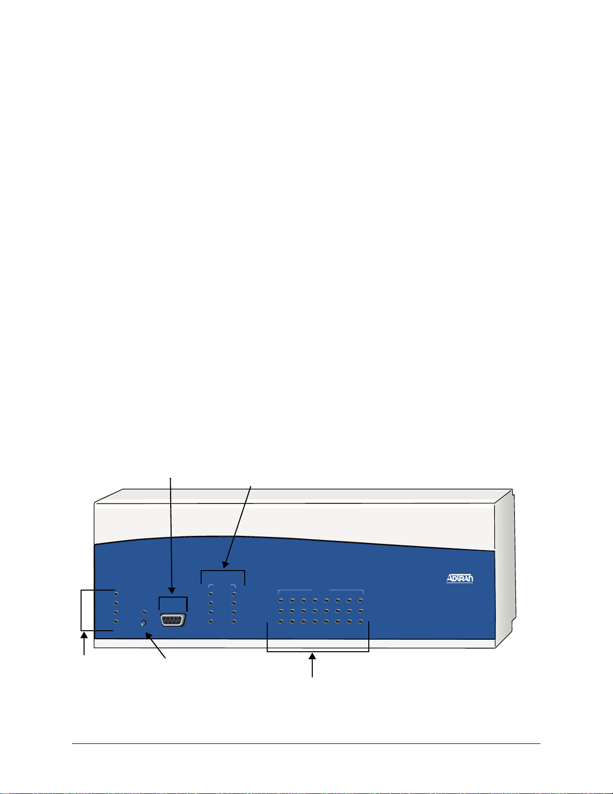
2. ATLAS 830 FRONT PANEL
The ATLAS 830 front panel contains the Alarm Cut-off (ACO) switch, the CRAFT port, and status LEDs
for the system (
MODULE). Figure 1 locates these features and Table 1 on page 17 further describes their functions.
ule (
POWER, SYSTEM, ETHERNET, and REMOTE), network (NETWORK), and option mod-
CRAFT port
Network LEDs
(Slot 0, Ports 1&2)
NET WORK
1
System
LEDs
POWER
SYSTEM
ETHERNET
REMOTE
ACO
CRAFT
ACO
Switch
OK
TEST
ERROR
ALARM
2
OK
TEST
ERROR
ALARM
STATUS
ONLINE
1
TEST
Module Status LEDs
MODULES
3
5
2
4
7
6
8
ATLAS 830
Figure 1. ATLAS 830 Front Panel Layout
61200780L1-1C © 2004 ADTRAN, Inc. 16
Page 17

ATLAS 800 Series System Manual ATLAS 830 Front Panel
Engineering Guidelines
ACO Switch
The ACO switch clears the Alarm Relay (located on the rear panel) after an alarm condition has occurred.
If an alarm condition is corrected and then reoccurs, the Alarm Relay activates again.
CRAFT Port
Use the CRAFT port (see Pinout 1) to configure the system via an EIA-232 connection.
Pinout 1. ATLAS 830 CRAFT Port (DB-9, female)
Pin Name Description
1 DCD Data Carrier Detect (output)—not connected
2 RD Receive Data (output)
3 TD Transmit Data (input)
4 DTR Data T erminal Ready (input)—not connected
5 SG Signal Ground
6 DSR Data Set Ready (output)—not connected
7 RTS Request to Send (input)—not connected
8 CTS Clear to Send (output)— not connected
9 RI Ring Indicate (output)—not connected
Front Panel LEDs
With the ATLAS 830 powered-up, the front panel LEDs provide visual information about the status of the
ATLAS 830 and any option modules that may be installed. Table 1 describes the purpose of the front panel
LEDs, and Table 2 on page 19 provides information about the meaning of the LED colors.
Table 1. ATLAS 830 Front Panel LEDs’ Purpose
LED Purpose
System
Power Indicates the status of the power supply.
System Indicates the status of the unit controller and other system parameters.
Displays the status of the power supply, controller, and other system
parameters for the ATLAS 830 (see Table 2 on page 19).
Ethernet Indicates the status of the Ethernet port.
Remote Indicates whether a user (Telnet or VT100) is logged into the unit.
61200780L1-1C © 2004 ADTRAN, Inc. 17
Page 18

ATLAS 800 Series System Manual ATLAS 830 Front Panel
Engineering Guidelines
Table 1. ATLAS 830 Front Panel LEDs’ Purpose (Continued)
LED Purpose
Network
Displays the status of the two built-in T1/PRI interfaces on the rear panel
of the unit. (These are referred to in the menus as Slot 0, Ports 1 and 2.)
OK Indicates that the network interface has passed self-test and is operating
correctly.
Test Indicates that there is an active test on the T1/PRI interface.
Error Blinks to indicate the occurrence of error events such as clock slip
seconds (CSS), bipolar violations (BPV), errored seconds (ES), etc.
Alarm Indicates an active alarm condition on the T1/PRI interface.
ACO
Modules
Indicates the status of the ACO switch.
Displays by row the operational condition of each module installed in the
option slots. All LEDs will be off if no option module is installed or
configured.
Status Indicates the operational condition of modules installed in the option
slots.
Online Indicates whether the module is available for use or is currently in use. If
the module is manually taken offline, this LED is turned off.
Test Indicates that one or more ports within a module are in test.
ACO
CRAFT
Clears the Alarm Relay connection located on the rear panel of the
ATLAS 830.
Allows the ATLAS 830 to connect to a computer using a VT100 terminal
or terminal emulator.
61200780L1-1C © 2004 ADTRAN, Inc. 18
Page 19

ATLAS 800 Series System Manual ATLAS 830 Front Panel
Engineering Guidelines
Table 2. ATLAS 830 LED Descriptions
For these LEDs... This color light... Indicates that...
System
Power Red (solid) Power supply error condition or temperature alarm.
Green The unit is on and connected to a power source.
Off The unit is off.
System Green (solid) No diagnosed system faults were found.
Green (fast blink) System Controller is offline.
Yellow (fast blink) Flash download is in progress.
Yellow (solid) Se lf-test in progress.
Red (solid) Internal error condition.
Red (fast blink) Flash download or flash error condition.
Off Power is not currently supplied to the system or the
power switch is in the off position.
Ethernet Green Link has been established.
Off Link has not been established.
Remote Yellow A user is logged into the unit via Telnet or VT100.
Off No users are logged into the unit.
ACO
Yellow ACO switch is depressed.
Off ACO switch is not depressed.
Network
OK Green (solid) The network T1/PRI interface is operating normally with
error-free operation.
Off The interface has experienced an alarm.
TEST Yellow (solid) The T1/PRI interface is in a test mode.
ERROR Red (blinking) Blinks with the occurrence of an error event including
BPV, CRC, and ES.
ALARM Red (solid) The T1/PRI interface is experiencing an alarm such as
loss of frame (LOF), loss of signal (LOS), etc.
61200780L1-1C © 2004 ADTRAN, Inc. 19
Page 20

ATLAS 800 Series System Manual ATLAS 830 Rear Panel
Engineering Guidelines
Table 2. ATLAS 830 LED Descriptions (Continued)
For these LEDs... This color light... Indicates that...
Modules
Status Green (solid) Module is present.
Green (fast blink) Module has been manually taken offline by the user.
Red (solid) Module is in an alarm state.
Red (fast blink) Module has no response, has been removed, or is not
supported.
Red (slow blink) Module is not ready.
None No module occupies the slot.
Online Green (solid) Module has an active connection.
Green (fast blink) Module has invalid flash memory or is downloading
firmware.
Test Yellow (solid) Module is in a test mode.
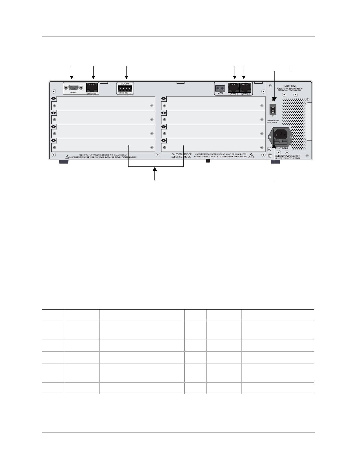
3. ATLAS 830 REAR PANEL
The ATLAS 830 rear panel (see Figure 2) contains an ADMIN port for connecting to a VT100 terminal (or
terminal emulator) or modem, a 10/100BaseT interface for
built-in T1/PRI network interfaces (
NTWK1 and NTWK2) and eight slots for housing option modules
which provide a variety of additional resources and data ports. All slots are functionally identical. An
optional redundant power supply may be installed in slots 7 and 8. In addition, the
POWER SUPPLY are located on the rear panel.
ETHERNET access, ALARM contacts, two
ON/OFF switch and
61200780L1-1C © 2004 ADTRAN, Inc. 20
Page 21
ATLAS 800 Series System Manual ATLAS 830 Rear Panel
Engineering Guidelines
ADMIN
Port
Ethernet
Port
Slot 1
Slot 2
Slot 3
Slot 4
Alarm
Contacts
Option Module Slots
Figure 2. ATLAS 830 Rear Panel
Slot 5
Slot 6
Slot 7
Slot 8
T1/PRI
Interfaces
Power Supply
Power On/Off
Switch
Admin Port
The ADMIN port (EIA-232, see Pinout 2 on page 21) connects to a computer or modem and provides the
following functions:
• Accepts EIA-232 input from a PC or a modem for controlling the ATLAS 830.
• Operates at 2400, 9600, 19200, or 38400 bps.
• Acts as input for either VT100 or PC control.
• Acts as an interface for flash memory software downloads using XMODEM.
Pinout 2. ATLAS 830 Admin Port (DB-9, female)
Pin Name Description Pin Name D escription
1DCDData Carrier Detect (output) 6DSRData Set Ready (output
— not connected
2RDReceive Data (output) 7RTSRequest to Send (input)
3TDTransmit Data (input) 8CTSClear to Send (output)
4DTRData Terminal Ready (input) 9RI Ring Indicate (output)
— not connected
5SG Signal Ground
61200780L1-1C © 2004 ADTRAN, Inc. 21
Page 22

ATLAS 800 Series System Manual ATLAS 830 Rear Panel
Engineering Guidelines
10/100BaseT Connection
The 10/100BaseT port (RJ-45) provides a 10/100BaseT Ethernet LAN connection, whic h is used for IP
Routing, TFTP, SNMP, and Telnet connections (see Pinout 3).
Pinout 3. ATLAS 830 Ethernet (RJ-45)
Pin Name Description
1 TX1 Transmit Positive
2 TX2 Transmit Negative
3 RX1 Receive Positive
4, 5 Unused —
6 RX2 Receive Negative
7, 8 Unused —
Alarm Relay Connection
This connection alerts the user when a pre-selected alarm condition exists (see Pinout 4). The four-pin,
removable terminal block connects with external wiring. Refer to DLP-11, Connecting the Alarm
Contacts, on page 344 for detailed instructions. Clear the alarm condition by pressing the ACO switch
located on the front panel of the ATLAS 830.
Pinout 4. ATLAS 830 Alarm Relay Connector
Pin Name Description
1 NC Normally closed, but opens when a pre-selected alarm condition is present.
2 NO Normally open, but closes when a pre-selected alarm condition is present.
3 COM Common connection between external circuitry and NC or NO terminal.
4 GND The chassis ground.
MON
The MON IN and OUT Bantam test jacks provide a bridged access jack for nonintrusive monitoring of the
incoming T1. When connected to this jack, configure the test equipment for bridged termination.
T1/PRI Connections
Each of the T1/PRI ports, NTWK1 and NTWK2, uses a single eight-position modular jack to connect to the
T1 or PRI circuit. Pinout 5 shows the pinout for this connector.
61200780L1-1C © 2004 ADTRAN, Inc. 22
Page 23

ATLAS 800 Series System Manual ATLAS 830 At-A-Glance Specifications
Engineering Guidelines
Pinout 5. ATLAS 830 T1/PRI
Pin Name Description
1 RxData-Ring (R) Receive data from the network
2 RxData-Tip (T) Receive data from the network
3 Unused —
4 TxData-Ring (R1) Send data towards the network
5 TxData-Tip (T1) Send data towards the network
6,7,8 Unused —
4. ATLAS 830 AT-A-GLANCE SPECIFICATIONS
Table 3 lists the specifications for the ATLAS 830 system.
Table 3. ATLAS 830 Specifications
Application Feature Specification
Operating Specifications
Temperature Operation: 0°C to 45°C
Relative Humidity To 95% noncondensing
TDM Applications
TDM bandwidth 46 Mbps Full duplex
Dedicated map connections 766 dedicated DS0 map connections in each
Storage: -40°C to 70°C
of the 5 maps
61200780L1-1C © 2004 ADTRAN, Inc. 23
Page 24

ATLAS 800 Series System Manual ATLAS 830 At-A-Glance Specifications
Engineering Guidelines
Table 3. ATLAS 830 Specifications (Continued)
Application Feature Specification
Switching Applications
ISDN signaling types National ISDN
Lucent 5E
AT&T 4ESS (PRI Only)
Northern DMS-100 (Nortel Custom)
Euro ISDN
T1 signaling types Loop-Start
Ground-Start
E&M Wink
E&M Immediate
Feature Group D
DSP Features DTMF/MF tones support
Progress tone generation
32 available DSP channels
27 simultaneous dial tones
BRI Connections
(recommended)
PRI Connections
(recommended)
RBS T1 Connections
(recommended)
64 connections
345 B channels and 15 D channels
120 DS0 connections
61200780L1-1C © 2004 ADTRAN, Inc. 24
Page 25

ATLAS 800 Series System Manual ATLAS 830 At-A-Glance Specifications
Engineering Guidelines
Table 3. ATLAS 830 Specifications (Continued)
Application Feature Specification
Frame Relay
Packet throughput 7900 pkts/sec (based on 64 byte size
packets)
PPP
Management signaling
interfaces
UNI (user and network)
NNI
Management signaling types ANSI T1.617-D (Annex D)
ITU-T Q.933-A (Annex A)
LMI (Group of four)
Auto
Encapsulation RFC 1490
PVC support 24 PVCs per packet endpoint (DS0 limited,
24 PVCs for T1).
992 is the limit of PVCs allowed in the unit.
Congestion control FECN / BECN
Discard eligible (DE)
Quality of service (QOS) Prioritization on a per-PVC basis
Testing (ADTRAN
proprietary)
PVC loopback
Round trip delay measurement
SNMP support RFC 1315
Connection support 35 PPP connections to the internal router
(not exceeding 3200 packets per second)
100 PPP connections to the internal router
(requires HDLC Module and cannot exceed
3200 packets per second)
Authentication support PAP
CHAP
EAP
Keepalive support On/Off
Interface support Numbered interfaces
Unnumbered interfaces
61200780L1-1C © 2004 ADTRAN, Inc. 25
Page 26

ATLAS 800 Series System Manual ATLAS 890 Description
Engineering Guidelines
Table 3. ATLAS 830 Specifications (Continued)
Application Feature Specification
IP Routing
Route discovery RIP V1
RIP V2
ICMP
ARP
IARP
UDP Relay
SNMP support RFCs 1315, 1213, 1406
Adtran Enterprise MIB
Voice Compression
Algorithm Voice Compression Module
G.723.1 or Netcoder (proprietary)
Number of channels supported Up to 64 compression channels
PCM coding µ-Law
Fax support 9600 bps
DTMF generation and
TIA 464A
detection
5. ATLAS 890 DESCRIPTION
Equipment Dimensions
The ATLAS 890 base unit is 17.08” W, 11.67” D, and 10.5” H and can be mounted in a 19-inch or 23-inch
rack (mounting brackets are included in the shipment). All other equipment (option modules) fit inside the
base unit.
Power Requirements (AC System)
Regardless of the option modules configuration installed in the base unit, the A T LAS 890 AC system has a
maximum power consumption of 400 W and a maximum current draw of 7 A.
Power Requirements (DC System)
Regardless of the option modules configuration installed in the base unit, the A T LAS 890 DC system has a
maximum power consumption of 325W and a maximum current draw of 8 A at -48 VDC.
61200780L1-1C © 2004 ADTRAN, Inc. 26
Page 27
ATLAS 800 Series System Manual ATLAS 890 Front Panel
Engineering Guidelines
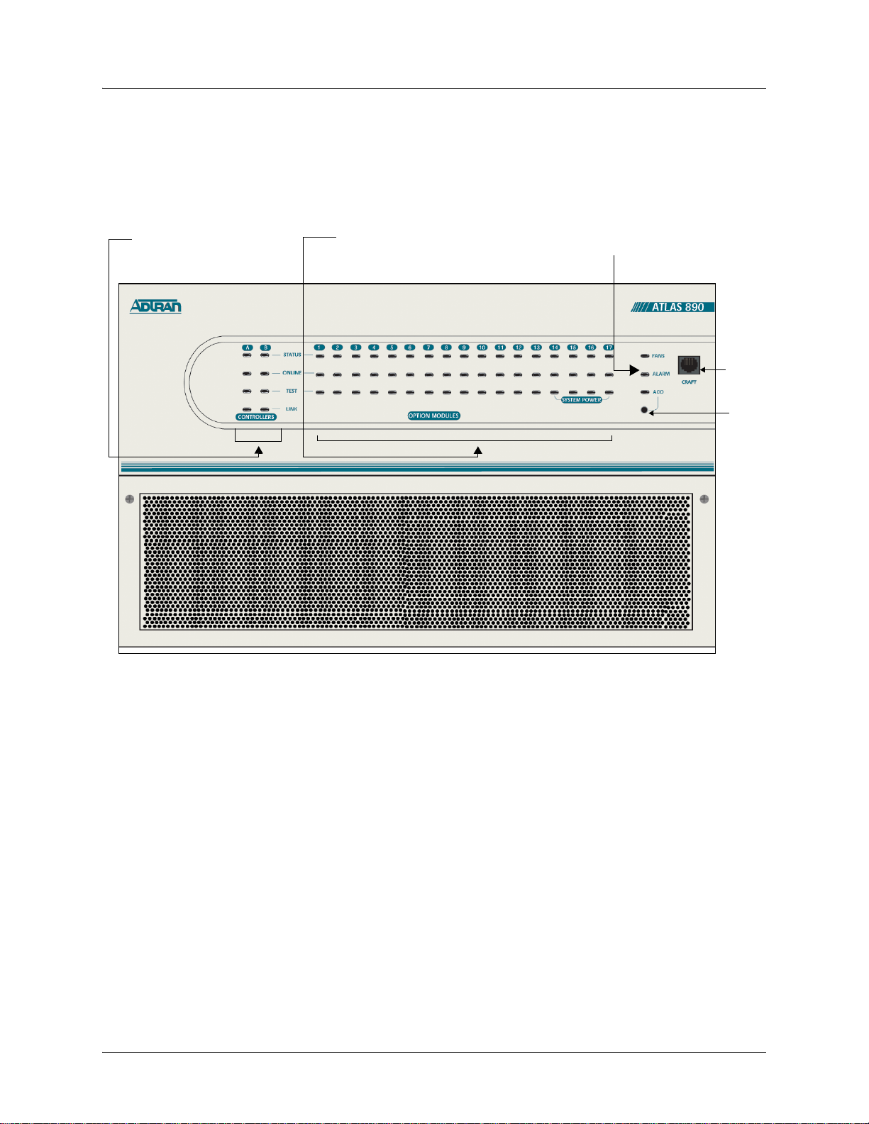
6. ATLAS 890 FRONT PANEL
The front panel contains the Alarm Cut-off (ACO) switch, the CRAFT port, and the controller and option
modules, and system (fans and alarm) status
ATLAS 890 base unit and any option module that may be installed. Figure 3 identifies these features.
LEDS. The LEDs provide visual information about the
Controller LEDs Option Module LEDs
System LEDs
CRAFT
Port
ACO
Switch
Figure 3. ATLAS 890 Front Panel Layout
ACO Switch
The ACO switch deactivates (clears) the Alarm Relay, located on the rear panel, after an alarm condition
has occurred. If an alarm condition is corrected and then reoccurs, the Alarm Relay activates again.
61200780L1-1C © 2004 ADTRAN, Inc. 27
Page 28

ATLAS 800 Series System Manual ATLAS 890 Front Panel
Engineering Guidelines
CRAFT Port
Use the CRAFT port (see Pinout 6) to connect to a computer to configure the system via an EIA-232
connection or to connect to a modem.
Pinout 6. ATLAS 890 CRAFT Port (RJ-48C)
Pin Name Description
1,2 Unused —
3 RXDATA Data received by the ATLAS 890
4Unused—
5 TXDATA Data transmitted by the ATLAS 890
6,7 Unused —
8Unused—
Front Panel LEDs
With the ATLAS 890 powered-up, the front panel LEDs provide visual information about the status of the
unit and any option modules that may be installed. Ta ble 4 describes the purpose of the front panel LEDs,
and Table 5 on page 29 provides information about the meaning of the LED colors.
Table 4. ATLAS 890 Front Panel LEDs’ Purpose
LED Purpose
System
Displays the status of the fans, alarm, and ACO buttons for the
ATLAS 890. (See Table 5 on page 29.)
Fans
Alarm
ACO
Controller Module
Indicates the fans are operational.
Indicates a triggered alarm condition for the alarm relays.
Indicates the alarm cut-off switch is pressed.
Displays the status of the network interface. All LEDs are off if no
network module is installed. (See Table 2 on page 19.)
Status
Indicates the operational condition of the controller installed in the
controller slot.
Online
Test
Indicates whether the module is available for use or is currently in use.
Indicates that the module is in test.
Link
Indicates there is an active 10/100 Ethernet connection on the installed
controller module.
61200780L1-1C © 2004 ADTRAN, Inc. 28
Page 29

ATLAS 800 Series System Manual ATLAS 890 Front Panel
Engineering Guidelines
Table 4. ATLAS 890 Front Panel LEDs’ Purpose (Continued)
LED Purpose
Option Module
Displays by row the operational condition of each module installed in the
option slots. All LEDs will be off if no option module is installed. (See
Table 5 on page 29.)
Status
Indicates the operational condition of modules installed in the option
slots.
Online
Indicates whether the module is available for use or is currently in use. If
the module is manually taken offline, this LED is turned off.
Test
Table 5. ATLAS 890 LED Description
For These Leds... This Color Light... Indicates That...
Fans
Indicates that one or more ports within a module are in test.
Red (solid) Fan speed is too low or fan is disconnected.
Amber (solid) Fan speed is too high.
Green (solid) All fans are functioning properly.
Alarm
Red (solid) A fan, external input, or power supply error has occurred.
LED will remain red until the ACO button is pressed.
ACO
Stand-by controller
Status
Online
Test
Link
Amber ACO button is being pressed.
Green (slow blink) Stand-by controller is present.
Green (solid) Stand-by controller operational for redundancy.
Red (fast blink) Controller cannot automatically become the active
controller while the current active controller is installed.
N/A N/A
Green (solid) Ethernet link detected.
61200780L1-1C © 2004 ADTRAN, Inc. 29
Page 30

ATLAS 800 Series System Manual ATLAS 890 Front Panel
Engineering Guidelines
Table 5. ATLAS 890 LED Description (Continued)
For These Leds... This Color Light... Indicates That...
Active controller
Status
Online
Test
Link
Module Status
Green
Card is not ready.
(slow blink)
Green
Card is not supported.
(fast blink)
Green (solid) Active controller present.
Amber (solid) Controller is in test mode.
Amber
Card is upgrading firmware.
(fast blink)
Red (fast blink) Flash parameters are not compatible.
Green (fast blink) Card is unresponsive or not supported.
Red (fast blink) Card is not ready .
Amber (solid) Controller is in test mode.
Green (solid) Ethernet link detected.
Green (solid) Module is present.
Green (fast blink) Module has been manually taken offline by the user.
Module Online
Module Test
Red (solid) Module failed self-test.
Red (fast blink) Module has no response, has been removed, or is not
supported.
Red (slow blink) Module is not ready.
None No module occupies the slot.
Green (solid) Module has an active connection.
Green (fast blink) Module has invalid flash memory or is downloading
firmware.
Yellow (solid) Module is in a test mode.
61200780L1-1C © 2004 ADTRAN, Inc. 30
Page 31

ATLAS 800 Series System Manual ATLAS 890 Rear Panel
Engineering Guidelines
7. ATLAS 890 REAR PANEL
The ATLAS 890 rear panel contains 16 slots for housing option modules which provide a variety of
additional resources and data ports (see Figure 4). All slots are functionally identical. The ATLAS 890 also
contains two slots for housing controller modules and a single slot dedicated for power supply use only.
The most common configuration is a fully redundant system with two system controllers and two power
supplies. A fully redundant AC-powered ATLAS 890 provides 13 option slots. A fully redundant
DC-powered ATLAS 890 provides 15 option slots.
ADMIN In
Port
Power
Connection
10/100BaseT
Port
Alarm Relay
Outputs
External
Input
Figure 4. ATLAS 890 Rear Panel
Chassis
Ground
Admin In Port
The ADMIN IN port (EIA-232) connects to a computer or modem (see Pinout 7 on page 32). The control
port input provides the following functions:
• Accepts EIA-232 input from a PC or a modem for controlling the ATLAS 890.
• Operates at 2400, 9600, 19200, or 38400 bps.
• Acts as input for either VT100 or PC control.
• Acts as an interface for flash memory software downloads using XMODEM.
61200780L1-1C © 2004 ADTRAN, Inc. 31
Page 32

ATLAS 800 Series System Manual ATLAS 890 Rear Panel
Engineering Guidelines
Pinout 7. ATLAS 890 Admin In (RJ-48C)
Pin Name Description
1 GND Ground—connected to unit chassis
2 RTS Request to send—low control
3 RxData Data received by the ATLAS 890
4 DTR Data terminal ready
5 TxDATA Data transmitted by the ATLAS 890
6 CD Carrier detect
7Unused—
8 CTS Clear to send—flow control
10/100BaseT Connection
The 10/100BaseT port (RJ-48C) provides a 10/100BaseT Ethernet LAN connection, which is used for IP
Routing, TFTP, SNMP, and Telnet connections (see Pinout 8).
Pinout 8. ATLAS 890 Ethernet (RJ-48C)
Pin Name Description
1 Tx1 Transmit Positive
2 Tx2 Transmit Negative
3 Rx1 Receive Positive
4, 5 Unused —
6 Rx2 Receive Negative
7, 8 Unused —
61200780L1-1C © 2004 ADTRAN, Inc. 32
Page 33

ATLAS 800 Series System Manual ATLAS 890 Rear Panel
Engineering Guidelines
Alarm Relay Connection
This connection alerts the user when a pre-selected alarm condition exists. The four-pin, removable
terminal block connects with external wiring (see Pinout 9). Refer to DLP-12, Connecting to the
ATLAS 890 External Input, for detailed instructions. Clear the alarm condition by pressing the ACO switch
located on the front panel of the ATLAS 890.
Pinout 9. ATLAS 890 Alarm Relay Connector
Pin Name Description
1 NC Normally closed, but opens when a preselected alarm condition is present.
2 NO Normally open, but closes when a preselected alarm condition is present.
3 COM Common connection between external circuitry and NC or NO terminal.
4 GND Chassis Ground
External Input Connection
This connection alerts the user when a pre-selected external alarm condition exists and could be used, for
example, to monitor a UPS with dry contacts or another ATLAS 890. The three-pin, removable terminal
block connects with external wiring (see Pinout 10). Refer to DLP-12, Connecting to the ATLAS 890
External Input, for detailed instructions. Clear the alarm condition by pressing the ACO switch located on
the ATLAS 890 front panel.
Pinout 10. ATLAS 890 External Relay Monitor Connector
Pin Name Description
1 Input Monitors for the presence or absence of -48 VDC
2 Vout -48 VDC @ 1 mA
3 GND Chassis Ground
61200780L1-1C © 2004 ADTRAN, Inc. 33
Page 34

ATLAS 800 Series System Manual ATLAS 890 At-A-Glance Specifications
Engineering Guidelines
8. ATLAS 890 AT-A-GLANCE SPECIFICATIONS
Table 6 lists the specifications for the ATLAS 890 system.
Table 6. ATLAS 890 Specifications
Application Feature Specification
TDM Applications
TDM bandwidth 49 Mbps Full duplex
Dedicated map connections 766 dedicated DS0 map connections in
each of the 5 maps
Switching Applications
ISDN signaling types National ISDN
Lucent 5E
AT&T 4ESS (PRI Only)
Northern DMS-100 (Nortel Custom)
ETSI/DSS1
T1 signaling types Loop-Start
Ground-Start
E&M Wink
E&M Immediate
Feature Group D
DSP Features DTMF/MF tones support
Progress tone generation
32 available DSP channels
BRI Connections 128 connections
PRI Connections 766 DS0 connections
RBS T1 Connections 766 DS0 connections
27 simultaneous dial tones
61200780L1-1C © 2004 ADTRAN, Inc. 34
Page 35

ATLAS 800 Series System Manual ATLAS 890 At-A-Glance Specifications
Engineering Guidelines
Table 6. ATLAS 890 Specifications (Continued)
Application Feature Specification
Frame Relay
Packet throughput 11,700 pkts/sec (64-1500 size packets)
PPP
Management signaling
interfaces
UNI (user and network)
NNI
Management signaling types ANSI T1.617-D (Annex D)
ITU-T Q.933-A (Annex A)
LMI (Group of four)
Auto
Encapsulation RFC 1490
PVC support 990 PVCs per packet endpoint
Congestion control FECN / BECN
Discard eligible (DE)
Quality of service (QOS) Prioritization on a per-PVC basis
Testing (ADTRAN
proprietary)
PVC loopback
Round trip delay measurement
SNMP support RFC 1315
Connection support 35 PPP connections to the internal router
(not exceeding 11,700 packets per second)
100 PPP connections to the internal router
(requires HDLC Module and cannot exceed
11,700 packets per second)
Authentication support
PAP
CHAP
EAP
Keepalive support On/Off
Interface support Numbered interfaces
Unnumbered interfaces
61200780L1-1C © 2004 ADTRAN, Inc. 35
Page 36

ATLAS 800 Series System Manual Option Module Pinouts
Engineering Guidelines
Table 6. ATLAS 890 Specifications (Continued)
Application Feature Specification
IP Routing
Route discovery RIP V1
RIP V2
ICMP
ARP
IARP
UDP Relay
SNMP support RFCs 1315, 1213, 1406
Adtran Enterprise MIB
Voice Compression
Algorithm Voice Compression Module
G.723.1 or Netcoder (proprietary)
Number of channels supported Up to 64 compression channels
PCM coding µ-Law
Fax support 9600 bps
DTMF generation and
TIA 464A
detection
9. OPTION MODULE PINOUTS
Pinouts for all of the available options modules are included here.
Quad T1/PRI Option Module
Each port of the Quad T1/PRI Option Module (P/N 1200185L3) uses a single, eight-position modular jack
to connect to the T1 or PRI circuit (see Pinout 11).
Pinout 11. Quad T1/PRI Module (USOC RJ-48C)
Pin Name Description
1 RxData-Ring (R) Receive data from the network
2 RxData-Tip (T) Receive data from the network
3Unused —
4 TxData-Ring (R1) Send data towards the network
5 TxData-Tip (T1) Send data towards the network
6,7,8 Unused —
61200780L1-1C © 2004 ADTRAN, Inc. 36
Page 37

ATLAS 800 Series System Manual Option Module Pinouts
Engineering Guidelines
Quad E1/PRA Option Module
Using the provided adapter cables, the DB-62 port of the Quad E1/PRA Option Mo dule (P/N 1200264L1)
supplies a DB-15 connection (see Pinout 12). See Pinout 13 for the DB-62 interface pinout.
Pinout 12. Quad E1/PRA Module (DB-15)
Pin Name Description
1 RT Receive Tip
2 GND Ground
3 TT Transmit Tip
4 GND Ground
5 GND Ground
7 GND Ground
9 RR Receive Ring
11 TR Transmit Ring
Pinout 13. Quad E1/PRA Module (DB-62)
Pin Name Description Pin Name Description
1
1
P4 TT Port 4 Transmit Tip 42 GND Ground
2P4 TRPort 4 Transmit Ring 43 P4 RT Port 4 Receive Tip
3 GND Ground 44 P4 RR Port 4 Receive Ring
6 GND Ground 45 GND Ground
7P3 TTPort 3 Transmit Tip 48 GND Ground
8P3 TRPort 3 Transmit Ring 49 P3 RT Port 3 Receive Tip
9 GND Ground 50 P3 RR Port 3 Receive Ring
12 GND Ground 51 GND Ground
13 P2 TT Port 2 Transmit Tip 54 GND Ground
14 P2 TR Port 2 Transmit Ring 55 P2 RT Port 2 Receive Tip
15 GND Ground 56 P2 RR Port 2 Receive Ring
18 GND Ground 57 GND Ground
19 P1 TT Port 1 Transmit Tip 60 GND Ground
20 P1 TR Port 1 Transmit Ring 61 P1 RT Port 1 Receive Tip
21 GND Ground 62 P1 RR Port 1 Receive Ring
1
Pins that are not identified are not used. P(1-4) indicates the Port
61200780L1-1C © 2004 ADTRAN, Inc. 37
Page 38

ATLAS 800 Series System Manual Option Module Pinouts
Engineering Guidelines
Quad Nx 56/64 Option Module
Using the provided adapter cables, each DB-78 port of the Quad Nx 56/64 Option Module
(P/N 1200184L1) supplies a V.35 Winchester-style connection (see Pinout 14). Pinout 15 shows the DB-78
interface pinout.
Pinout 14. Quad Nx 56/64 Module (V.35 Winchester)
Pin CCITT Description Pin CCITT Description
A 101 Protective ground (PG) V 115 RX clock (RC-A) to DTE
B 102 Signal ground (SG) X 115 RX clock (RC-B) to DTE
C 105 Request to send (RTS) from
DTE
P 103 Transmitted data (TD-A) from
DTE
D 106 Clear to send (CTS) to DTE S 103 Transmitted data (TD-B) from
DTE
E 107 Data set ready (DSR) to DTE Y 114 TX clock (TC-A) to DTE
F 109 Received line signal detector
AA 114 TX clock (TC-B) to DTE
(DCD) to DTE
H — Data terminal ready (DTR)
from DTE
U 113 External TX clock (ETC-A) from
DTE
J — Ring indicator (RI) W 113 External TX clock (ETC-B) from
DTE
R 104 Received data (RD-A) to DTE NN — Test mode (TM) to DTE
T 104 Received data (RD-B) to DTE
Pinout 15. Quad Nx 56/64 Module (DB-78)
Pin Signal Pin Signal
1
1
RXD-A 2/4 42 GND
2 RXD-B 2/4 43-48 Not used
3 RXC-A 2/4 49 MOD2
4 RXC-B 2/4 50 MOD0
5 TXD-A 2/4 51 EXT-TXC-A 1/3
6 TXD-B 2/4 52 DTR-B 1/3
7 TXC-A 2/4 53 DTR-A 1/3
8 TXC-B 2/4 54 DCD-B 1/3
9 EXT-TXC-A 2/4 55 DCD-A 1/3
61200780L1-1C © 2004 ADTRAN, Inc. 38
Page 39

ATLAS 800 Series System Manual Option Module Pinouts
Engineering Guidelines
Pinout 15. Quad Nx 56/64 Module (DB-78) (Continued)
Pin Signal Pin Signal
10 EXT-TXC-A 2/4 56 DSR-B/RI 1/3
11-17 Not used 57 DSR-A 1/3
18 GND 58 CTS-B 1/3
19 GND 59 CTS-A 1/3
20 CHASIS GND 60 CHASIS GND
21 CTS-A 2/4 61 GND
22 CST-B 2/4 62-68 Not used
23 DSR-A 2/4 69 MOD1
24 DSSR-B/RI 2/4 70 EXT-TXC-B 1/3
25 DCD-A 2/4 71 TXC-B 1/3
26 DCD-B 2/4 72 TXC-A 1/3
27 DTR-A 2/4 73 TXD-B 1/3
28 DTR-B 2/4 74 TXD-A 1/3
29-37 Not used 75 RXC-B 1/3
38 RTS-A 1/3 76 RXC-A 1/3
39 RTS-B 1/3 77 RXD-B 1/3
40 RTS-A 2/4 78 RXD-A 1/3
41 RTS-B 2/4
1
1/3 or 2/4 indicates the port on the Nx 56/64 Module
61200780L1-1C © 2004 ADTRAN, Inc. 39
Page 40

ATLAS 800 Series System Manual Option Module Pinouts
Engineering Guidelines
Quad USSI Option Module
Pinouts 16 through 20 on the following pages describe the available interfaces for the Quad USSI Option
Module (P/N 4200261Lx).
Pinout 16. Quad USSI Module (DB-78)
Pin Signal Description Pin Signal Description Pin
1
1
RXD-A 2/4 25 DCD-A 2/4 57 DSR-A 1/3
Signal
Description
2 RXD-B 2/4 26 DCD-B 2/4 58 CTS-B 1/3
3 RXC-A 2/4 27 DTR-A 2/4 59 CTS-A 1/3
4 RXC-B 2/4 28 DTR-B 2/4 60 CHASIS GND
5 TXD-A 2/4 29-37 Not used 61 GND
6 TXD-B 2/4 38 RTS-A 1/3 62-68 Not used
7 TXC-A 2/4 39 RTS-B 1/3 69 MOD1
8 TXC-B 2/4 40 RTS-A 2/4 70 EXT-TXC-B 1/3
9 EXT-TXC-A 2/4 41 RTS-B 2/4 71 TXC-B 1/3
10 EXT-TXC-A 2/4 43-48 Not used 72 TXC-A 1/3
11-17 Not used 49 MOD2 73 TXD-B 1/3
18 GND 50 MOD0 74 TXD-A 1/3
19 GND 51 EXT-TXC-A 1/3 75 RXC-B 1/3
20 CHASIS GND 52 DTR-B 1/3 76 RXC-A 1/3
21 CTS-A 2/4 53 DTR-A 1/3 77 RXD-B 1/3
22 CST-B 2/4 54 DCD-B 1/3 78 RXD-A 1/3
23 DSR-A 2/4 55 DCD-A 1/3
24 DSSR-B/RI 2/4 56 DSR-B/RI 1/3
1
1/3 or 2/4 indicates the port on the USSI Module
61200780L1-1C © 2004 ADTRAN, Inc. 40
Page 41

ATLAS 800 Series System Manual Option Module Pinouts
Engineering Guidelines
Pinout 17. Quad USSI Module (EIA-530)
Pin Signal Description Pin Signal Description Pin Signal Description
1 Shield (Ground) 10 Carrier Detect (B) 19 Request to Send (B)
2 Transmit Data (A) 11 Ext. Transmit Clock (B) 20 DTE Ready (A)
3 Receive d Data (A) 12 Transmit Clock (B) 21 Remote Loopback
4 Request to Send (A) 13 Clear to Send (B) 22 DCE Ready (B)
5 Clear to Send (A) 14 Transmit Data (B) 23 DTE Ready (B)
6 DCE Ready (A) 15 Transmit Clock (A) 24 Ext. Transmit Clock (A)
7 Signal Ground 16 Received Data (B) 25 Test Mode
8 Carrier Detect (A) 17 Receive Clock (A)
9 Received Clock (B) 18 Local Loopback
Pinout 18. Quad USSI Module (RS-449/V.36)
Pin Signal Description Pin Signal Description Pin Signal Description
1 Shield (Ground) 14 Remote Loopback 2 7 Clear to Send (B)
2 Signaling Rate
15 Ring Indicator 28 Terminal in Service
Indicator
3 Not Used 16 Select Frequency 29 DCE Ready (B)
4 Transmit Data (A) 17 Ext. Transmit Clock (A) 30 DTE Ready (B)
5 Transmit Clock (A) 18 Test Mode 31 Carrier Detect (B)
6 Received Data (A) 19 Signal Ground 32 Select Standby
7 Request to Send (A) 20 Receive Common 33 Signal Quality
8 Receive Clock (A) 21 Not Used 34 New Signal
9 Clear to Send (A) 22 Transmit Data (B) 35 Ext. Transmit Clock (B)
10 Local Loopback 23 Transmit Clock (B) 36 Standby/Indicator
11 DCE Ready (A) 24 Receive Data (B) 37 Send Common
12 DTE Ready (A) 25 Request to Send (B)
13 Carrier Detect (A) 26 Receive Clock (B)
61200780L1-1C © 2004 ADTRAN, Inc. 41
Page 42

ATLAS 800 Series System Manual Option Module Pinouts
Engineering Guidelines
Pinout 19. Quad USSI Module (RS-232)
Pin Signal Description Pin Signal Description
1 Shield (Ground) 14 Sec. Transmit Data
2 Transmit Data 15 DCE Transmit Clock
3 Received Data 16 Sec. Received Data
4 Request to Send 17 Receive Signal Element Timing
5 Clear to Send 18 Not used
6 Data Set Ready 19 Sec. Request to Send
7 Signal Ground 20 Data Terminal Ready
8 Received Line Signal Detector 21 Signal Quality Detector
9 + Voltage 22 Ring Indicator
10 - Voltage 23 Data Signal Rate Selector
11 Not used 24 DTE Transmit Clock
12 Sec. Received Line Signal Indicator 25 Not used
13 Sec. Clear to Send
Pinout 20. Quad USSI Module (CCITT X.21 V.11 )
Pin Signal Description Pin Signal Description
1 Shield (Ground) 8 Signal Ground
2 Transmit Data (A) 9 Transmit Data (B)
3 Request to Send (A) 10 Request to Send (B)
4 Received Data (A) 11 Received Data (B)
5 Carrier Detect (A) 12 Carrier Detect (B)
6 Transmit/Receive Clock (A) 13 Transmit/Received Clock (B)
7 Ext. Transmit Clock (A) 14 Ext. Transmit Clock (B)
15 Not Used
61200780L1-1C © 2004 ADTRAN, Inc. 42
Page 43

ATLAS 800 Series System Manual Option Module Pinouts
Engineering Guidelines
Octal BRI ISDN (U-Interface) Option Module
Each port of the Octal BRI ISDN (U-Interface) Option Module (P/N 1200186L2) uses a single RJ-45 jack
to connect to a standard BRI U interface circuit (see Pinout 21).
Pinout 21. Octal BRI (U-Interface) Module (RJ-45)
Pin Name Description
1, 2, 3, 6, 7, 8 Unused —
4 Ring Ring to and from the Network Interface
5 Tip Tip to and from the Network Interface
Octal BRI ISDN (S/T Interface) Option Module
Each port of the Octal BRI ISDN (S/T Interface) Option Module uses a single RJ-45 jack to connect to a
standard BRI S/T interface circuit (see Pinout 22). The Octal BRI ISDN (S/T Interface) Option Module is
only available for use in NT mode (User Term) applications.
Pinout 22. Octal BRI (S/T Interface) Module (RJ-45)
Pin Name Description
1, 2, 7, 8 Unused —
3, 6 Receive Receive for User Term (NT Mode)
4, 5 Transmit Transmit for User Term (NT Mode)
61200780L1-1C © 2004 ADTRAN, Inc. 43
Page 44

ATLAS 800 Series System Manual Option Module Pinouts
Engineering Guidelines
Async-232 Option Module
Using the provided adapter cables, each Async-232 Option Module (P/N 1200182L1) in terface p rovides a
DB-25 (see Pinout 23).
Pinout 23. Async-232 Option Module (DB-25)
Pin Name Description
1 Shield Shielded ground connection
2 TXD Transmit data from DTE
3 RXD Receive data to DTE
4 RTS Request to send from DTE
5 CTS Clear to send to DTE
6 DSR Data set ready to DTE
7 GND Ground
8 DCD Data carrier detect to DTE
9—19, 21, 23—25 Unused n/a
20 DTR Data terminal ready from DTE
22 RI Ring indicator to DTE
T3 Option Module
Using the provided RG 59, 75-Ohm cables (P/N 3125I054), each T3 Option Module (P/N 1200223L1)
provides BNC connectors for transmit and receive connections (see Pinout 24).
Pinout 24. T3 Module (BNC pair, female)
Name Description
RX IN Receive data from the network, 75 ohms ± 5%, unbalanced
TX OUT Transmit data to the network, 75 ohms ± 5%, unbalanced
61200780L1-1C © 2004 ADTRAN, Inc. 44
Page 45

ATLAS 800 Series System Manual Option Module Pinouts
Engineering Guidelines
T3 Drop and Insert Option Module
Using the provided RG-59, 75-Ohm cables (P/N 3125I054), each T3 Drop and Insert Option Module
(P/N 1200225L1) provides BNC connectors for primary and secondary transmit and receive connections
(see Pinout 25
Pinout 25. T3 Drop and Insert Module (BNC pair, female)
).
Name Description
Primary RX IN Primary receive data from the network, 75 ohms ± 5%, unbalanced
Primary TX OUT Primary transmit data to the network, 75 ohms ± 5%, unbalanced
Secondary RX IN Secondary receive data from the network, 75 ohms ± 5%, unbalanced
Secondary TX OUT Secondary transmit data to the network, 75 ohms ± 5%, unbalanced
Dual Video Option Module
The Dual Video Option Module (P/N 4200773Lx) provides a standard RS-366 dialing interface (DB-25)
and a DTE interface (provided through adapter cables). Pinout 26 shows the RS-366 dialing interface and
Pinouts 27 through 29 on the following pages show pinouts for the other available interfaces.
Pinout 26. Dual Video Module (RS-366, DB-25)
Pin Name Description Pin Name Description
1 Shield Shielded Ground Connection 14 NB1 Digit Signal Circuit 1
2 DPR Digit Present 15 NB2 Digit Signal Circuit 2
3 ACR Abandon Call and Retry 16 NB4 Digit Signal Circuit 4
4 CRQ Call Request 17 NB8 Digit Signal Circuit 8
5 PND Present Next Digit 18 RC Receive Common
6 PWI Power Indication 19 SC Send Common
7 SG Signal Ground 20-21 Unused n/a
8-12 Unused n/a 22 DLO Data Link Occupied
13 DSC Distant Station Connection 23-25 Unused n/a
61200780L1-1C © 2004 ADTRAN, Inc. 45
Page 46

ATLAS 800 Series System Manual Option Module Pinouts
Engineering Guidelines
Pinout 27. Dual Video Module (V.35 Winchester)
Pin CCITT Name Description
A101PG Protective ground
B102SG Signal ground
C105RTSRequest to send from DTE
D106CTSClear to send to DTE
E107DSRData set ready to DTE
F109DCDReceived line signal detector to DTE
H— DTRData terminal ready from DTE
J— RI Ring indicator
R104RD-AReceived data to DTE
T104RD-BReceived data to DTE
V 115 RC-A RX clock to DTE
X 115 RC-B RX clock to DTE
P 103 TD-A Transmitted data from DTE
S103TD-BTransmitted data from DTE
Y114TC-ATX clock to DTE
AA 114 TC-B TX clock to DTE
U 113 ETC-A External TX clock from DTE
W 113 ETC-B External TX clock from DTE
NN — TM Test mode to DTE - (Not Supported)
61200780L1-1C © 2004 ADTRAN, Inc. 46
Page 47

ATLAS 800 Series System Manual Option Module Pinouts
Engineering Guidelines
Pinout 28. Dual Video Module (EIA-530)
Pin Signal Description Pin Signal Description Pin Signal Description
1 Shield (Ground) 10 Carrier Detect (B) 19 Request to Send (B)
2 Transmit Data (A) 11 Ext. Transmit Clock (B) 20 DTE Ready (A)
3 Received Data (A) 12 Transmit Clock (B) 21 Not Used
4 Request to Send (A) 13 Clear to Send (B) 22 DCE Ready (B)
5 Clear to Send (A) 14 Transmit Data (B) 23 DTE Ready (B)
6 DCE Ready (A) 15 Transmit Clock (A) 24 Ext. Transmit Clock (A)
7 Signal Ground 16 Received Data (B) 25 Not Used
8 Carrier Detect (A) 17 Receive Clock (A)
9 Received Clock (B) 18 Not Used
Pinout 29. Dual Video Module (RS-449)
Pin Signal Description Pin Signal Description Pin Signal Description
1 Shield (Ground) 14 Remote Loopback
27 Clear to Send (B)
(Not Supported)
2 Not Used 15 Ring Indicator 28 Not Used
3 Not Used 16 Not Used 29 DCE Ready (B)
4 Transmit Data (A) 17 Ext. Transmit Clock (A) 30 DTE Ready (B)
5 Transmit Clock (A) 18 Test Mode
31 Carrier Detect (B)
(Not Supported)
6 Received Data (A) 19 Signal Ground 32 Not Used
7 Request to Send (A) 20 Not Used 33 Not Used
8 Receive Clock (A) 21 Not Used 34 Not Used
9 Clear to Send (A) 22 Transmit Data (B) 35 Ext. Transmit Clock (B)
10 Local Loopback
23 Transmit Clock (B) 36 Not Used
(Not Supported)
11 DCE Ready (A) 24 Receive Data (B) 37 Not Used
12 DTE Ready (A) 25 Request to Send (B)
13 Carrier Detect (A) 26 Receive Clock (B)
61200780L1-1C © 2004 ADTRAN, Inc. 47
Page 48

ATLAS 800 Series System Manual Option Module Pinouts
Engineering Guidelines
NxT1 HSSI/V.35 Option Module
The NxT1 HSSI/V/35 Option Module (P/N 1200771L1) uses a single 50 pin SCSI-II interface (or V.35
interface using an optional adapter cable) to combine eight T1s of data (a combination of eight using the
four NxT1 HSSI/V.35 Module T1 ports and other T1 ports installed in the system). See Pinouts 30 and 31.
Pinout 30. NxT1 HSSI/V.35 Module (RJ-48C)
Pin Name Description
1 RxData - Ring (R) Receive data from the network
2 RxData - Tip (T) Receive data from the network
3Unused —
4 TxData - Ring (R1) Send da ta towards the network
5 TxData-Tip (T1) Send data towards the network
6,7,8 Unused —
Pinout 31. NxT1 HSSI/V.35 Module (50-pin SCSI-II and V.35 Winchester)
Pin
(+ Side)
Pin
(- Side)
Direction Description
1 26 — HSSI SG - Signal Ground
2 27 O HSSI RT - Receive Timing
3 28 O HSSI CA - DCE Available
4 29 O HSSI RD - Receive Data
5 30 O HSSI LC - Loopback Circuit C
6 31 O HSSI ST - Send Timing
7 32 — HSSI SG - Signal Ground
8 33 I HSSI TA - DTE Available
9 34 I HSSI TT - Terminal Timing
10 35 I HSSI LA - Loopback Circuit A
11 36 I HSSI SD - Send Data
12 37 I HSSI LB - Loopback Circuit B
13 38 — HSSI SG - Signal Ground
— 39 — Ancillary to DCE (Reserved)
14 — I V.35 RTS - Request to Send
15 40 I V.35 TT Terminal Timing
61200780L1-1C © 2004 ADTRAN, Inc. 48
Page 49

ATLAS 800 Series System Manual Option Module Pinouts
Engineering Guidelines
Pinout 31. NxT1 HSSI/V.35 Module (50-pin SCSI-II and V.35 Winchester) (Continued)
Pin
(+ Side)
Pin
(- Side)
Direction Description
16 41 I V.35 SD Send Data
— 42 O V.35 DCD - Data Carrier Detect
17-18 43 — Ancillary to DCE (Reserved)
19 44 — HSSI SG - Signal Ground
20 45 O V.35 ST - Send Timing
21 46 O V.35 RT - Receive Timing
22 47 O V.35 RD - Receive Data
23 — O V.35 CTS - Clear to Send
— 48 I V.35 Ground/Present
24 49 O HSSI TM - Test Mode
25 50 — HSSI SG - Signal Ground
Octal FXS Option Module
The Octal FXS Option Module provides eight analog voice-grade interfaces. Each interface can operate in
loop-start or ground-start mode, providing talk battery, off-hook supervision, ringing, and E&M signaling
conversion. Call progress tones, where necessary, are provided to the modules by the ATLAS.
Pinout 32. Octal FXS Module (8-pin modular)
Pin Name Description
1,2,3,6,7,8 Unused —
4 Ring Ring to and from the analog phone interface
5 Tip Tip to and from the analog phone interface
61200780L1-1C © 2004 ADTRAN, Inc. 49
Page 50

SECTION 2 SYSTEM DESCRIPTION
Provides managers with an overview of the ATLAS 800 Series System.
This section contains general information and describes physical and operational
concepts, card functions, network relationships, provisioning, testing, alarm
status, and system monitoring. This section should be used in conjunction with
Section 1, Engineering Guidelines, on page 14 of the system manual.
Table of Contents
System Overview. . . . . . . . . . . . . . . . . . . . . . . . . . . . . . . . . . . . . . . . . . . . . . . . . . . . . . . . . . . . . . . . . . . 15
ATLAS 830 . . . . . . . . . . . . . . . . . . . . . . . . . . . . . . . . . . . . . . . . . . . . . . . . . . . . . . . . . . . . . . . . . . . . . 15
ATLAS 890 . . . . . . . . . . . . . . . . . . . . . . . . . . . . . . . . . . . . . . . . . . . . . . . . . . . . . . . . . . . . . . . . . . . . . 15
Features and Benefits . . . . . . . . . . . . . . . . . . . . . . . . . . . . . . . . . . . . . . . . . . . . . . . . . . . . . . . . . . . . . . 15
Configuration and Management . . . . . . . . . . . . . . . . . . . . . . . . . . . . . . . . . . . . . . . . . . . . . . . . . . . . . 15
Software Upgradeable . . . . . . . . . . . . . . . . . . . . . . . . . . . . . . . . . . . . . . . . . . . . . . . . . . . . . . . . . . . . 15
Signaling Support . . . . . . . . . . . . . . . . . . . . . . . . . . . . . . . . . . . . . . . . . . . . . . . . . . . . . . . . . . . . . . . . 16
ISDN Switch Types. . . . . . . . . . . . . . . . . . . . . . . . . . . . . . . . . . . . . . . . . . . . . . . . . . . . . . . . . . . . . . . 16
Dedicated Connection Maps. . . . . . . . . . . . . . . . . . . . . . . . . . . . . . . . . . . . . . . . . . . . . . . . . . . . . . . . 16
Switched Connection Maps. . . . . . . . . . . . . . . . . . . . . . . . . . . . . . . . . . . . . . . . . . . . . . . . . . . . . . . . . 16
Testing . . . . . . . . . . . . . . . . . . . . . . . . . . . . . . . . . . . . . . . . . . . . . . . . . . . . . . . . . . . . . . . . . . . . . . . . 16
Performance Monitoring . . . . . . . . . . . . . . . . . . . . . . . . . . . . . . . . . . . . . . . . . . . . . . . . . . . . . . . . . . . 16
Frame Relay . . . . . . . . . . . . . . . . . . . . . . . . . . . . . . . . . . . . . . . . . . . . . . . . . . . . . . . . . . . . . . . . . . . . 16
PPP Switching. . . . . . . . . . . . . . . . . . . . . . . . . . . . . . . . . . . . . . . . . . . . . . . . . . . . . . . . . . . . . . . . . . . 17
Option Modules Overview . . . . . . . . . . . . . . . . . . . . . . . . . . . . . . . . . . . . . . . . . . . . . . . . . . . . . . . . . . . 17
ATLAS 890 System Controller Module (P/N 1200322L1). . . . . . . . . . . . . . . . . . . . . . . . . . . . . . . . . . 18
Quad T1/PRI Option Module (P/N 1200185L3) . . . . . . . . . . . . . . . . . . . . . . . . . . . . . . . . . . . . . . . . . 18
Quad E1/PRA Option Module (P/N 1200264L1). . . . . . . . . . . . . . . . . . . . . . . . . . . . . . . . . . . . . . . . . 18
Quad Nx 56/64 Option Module (P/N 1200184L1). . . . . . . . . . . . . . . . . . . . . . . . . . . . . . . . . . . . . . . . 18
Quad USSI Option Module (P/N 4200261Lx) . . . . . . . . . . . . . . . . . . . . . . . . . . . . . . . . . . . . . . . . . . . 18
Octal Basic Rate ISDN (U-Interface) Option Module (1200186L2). . . . . . . . . . . . . . . . . . . . . . . . . . . 18
Octal Basic Rate ISDN (S/T Interface) Option Module (1200343L1) . . . . . . . . . . . . . . . . . . . . . . . . . 18
T3 Option Module (P/N 1200223L1). . . . . . . . . . . . . . . . . . . . . . . . . . . . . . . . . . . . . . . . . . . . . . . . . . 19
T3 Option Module with Drop and Insert Interface (P/N 1200225L1). . . . . . . . . . . . . . . . . . . . . . . . . . 19
Dual Video Option Module (P/N 4200773Lx) . . . . . . . . . . . . . . . . . . . . . . . . . . . . . . . . . . . . . . . . . . . 19
NxT1 HSSI/V.35 Option Module (1200771L1) . . . . . . . . . . . . . . . . . . . . . . . . . . . . . . . . . . . . . . . . . . 19
Octal FXS Option Module (P/N 1200338L1). . . . . . . . . . . . . . . . . . . . . . . . . . . . . . . . . . . . . . . . . . . . 19
8,16,24,32 Channel Voice Compression Resource Modules (P/N 1200221Lx). . . . . . . . . . . . . . . . . 19
Nx 56/64 BONDing Resource Module (P/N 1200262L1) . . . . . . . . . . . . . . . . . . . . . . . . . . . . . . . . . . 19
HDLC Resource Module (P/N 1200222L1). . . . . . . . . . . . . . . . . . . . . . . . . . . . . . . . . . . . . . . . . . . . . 20
Modem-16 Resource Module (P/N 1200181L1). . . . . . . . . . . . . . . . . . . . . . . . . . . . . . . . . . . . . . . . . 20
Modem-24 Resource Module (P/N 1200782L1). . . . . . . . . . . . . . . . . . . . . . . . . . . . . . . . . . . . . . . . . 20
Async-232 Option Module (P/N 1200182L1) . . . . . . . . . . . . . . . . . . . . . . . . . . . . . . . . . . . . . . . . . . . 20
61200780L1-1C © 2004 ADTRAN, Inc. 50
Page 51

ATLAS 800 Series System Manual System Overview
System Description
1. SYSTEM OVERVIEW
The ATLAS 800 Series’ modular and highly scalable platform provides robust solutions for the wide-area
communication needs of medium-to-large corporations and network access providers. The ATLAS 800
Series is an Integrated Access System with extensive support of dedicated bandwidth management and
access switching. It contains a high-performance CPU and powerful communications drivers which
support applications such as frame relay and call switching.
With the ATLAS 800 Series, you can consolidate voice, data, and video applications into a single platform
while optimizing wide-area bandwidth and reducing equipment costs. The ATLAS 800 Series
architecture’s expansion slots allows for a variety of modules, making it one of the most versatile access
systems on the market.
ATLAS 830
The ATLAS 830 architecture includes a packet switching and a circuit switching bussing scheme. The
result is a system that supports bandwidth requirements of up to 30 T1 or Primary Rate ISDN (PRI)
circuits. Designed for standalone or rackmount use, the ATLAS 830 provides eight expansion slots that
accommodate hot-swappable option modules. A redundant power supply may be installed in slots 7 and 8,
if desired. A 10/100BaseT Ethernet connection for IP routing and network management and two onboard
T1/PRI interfaces are standard with the ATLAS 830.
ATLAS 890
The ATLAS 890 architecture includes a packet switching and a circuit switching bussing scheme. The
result is a system that supports bandwidth requirements of up to 30 T1 or Primary Rate ISDN (PRI)
circuits. Designed for standalone or rackmount use, the ATLAS 890 base unit provides two hot-swappable,
redundant system controller slots and up to 16 expansion slots that accommodate hot-swappable option
modules and up to four hot-swappable, redundant power supplies for a variety of applications. A
10/100BaseT Ethernet connection for IP routing and network management is standard with the
ATLAS 890 System Controller Module.
2. FEATURES AND BENEFITS
The following sections briefly describe features and benefits of the ATLAS 800 Series systems.
Configuration and Management
• VT100 Emulation
• SNMP, per MIB II (RFC1213), DS1 MIB (RFC1406), and ADTRAN private MIBs
•Telnet
• Dial-up, remote management via external analog modem
• Six levels of password protection and privileges
Software Upgradeable
• Flash memory
• TFTP download
• XMODEM via control port
61200780L1-1C © 2004 ADTRAN, Inc. 51
Page 52

ATLAS 800 Series System Manual Features and Benefits
System Description
Signaling Support
• ISDN D Channel
• Robbed Bit, E&M, Ground Start, Loop Start
• Convert between Robbed Bit Signaling and ISDN D Channel
• Direct Inward Dialing
ISDN Switch Types
• 5ESS™, DMS-100™, National ISDN, 4ESS™, Euro ISDN (ATLAS 830 only)
Dedicated Connection Maps
• Up to five connection maps
• Time of day/day of week configurable
• Preserves signaling through cross-connect
• No effect on unconfigured channels
Switched Connection Maps
• Inbound and outbound call filtering and blocking
Testing
• Local and remote: payload/line, V.54 (depending on installed modules)
• Patterns: 511, QRSS, all ones, all zeros (depending on installed modules)
Performance Monitoring
• Reports: Information for the ATLAS is stored for the last 24 hours, last 15 minutes, and last 5 minutes.
• ATLAS 830 can store frame relay performance at user-specified intervals (5, 10, 15, 20, 30 mins).
• Performance statistics per TR54016, T1.403, RFC1406
• Alarm reporting per TR54016, T1.403
Frame Relay
• Routes Internet Protocol (IP) traffic between the Ethernet port and a public frame relay network, a
private frame relay network, or a point-to-point (PPP) network.
• Concentrates IP traffic from a public or private frame relay network to one or more serial ports (V.35).
The protocol passed over the serial port is frame relay (RFC 1490 encapsulation).
• Passes Systems Network Architecture (SNA), Bisync, and other legacy protocols between a public or
private frame relay network and an external DTE running frame relay to the ATLAS.
• Performs voice compression/decompression (G.723.1) and interfaces to either a Private Branch
Exchange (PBX) or the Public Switched Telephone Network (PSTN). This feature requires an
additional option module, the VCOM Module—P/N 1200221Lx.
• Supports LMI, Annex D, or Annex A signaling on fram e relay connections.
61200780L1-1C © 2004 ADTRAN, Inc. 52
Page 53

ATLAS 800 Series System Manual Option Modules Overview
System Description
PPP Switching
• Supports up to 100 simultaneous PPP conn ections.
• Performs PAP, CHAP, or EAP authentication methods on a per connection basis.
• Includes keepalive functionality for PPP connections.
• Provides capability for numbered or unnumbered PPP interfaces.
3. OPTION MODULES OVERVIEW
Each option module is hot-swappable with configuration restored upon replacement. The following option
modules are available in an ATLAS chassis:
Module Name Part Number ATLAS 830 ATLAS 890
ATLAS 890 System Controller 1200322L1 n/a *
Quad T1/PRI Option Module 1200185L3 * *
Quad E1/PRA Option Module 1200264L1 * *
Quad Nx 56/64 Option Module 1200184L1 * *
Quad USSI Option Module 4200261Lx * *
Octal Basic Rate ISDN (U-Interface) Option Module 1200186L2 * *
Octal Basic Rate ISDN (S/T Interface) Option Module 1200343L1 * *
T3 Option Module 1200223L1 * *
T3 Option Module with Drop and Insert Interface 1200225L1 * *
Dual Video Option Module 4200773Lx * *
NxT1 HSSI/V.35 Option Module 1200771L1 * *
Octal FXS Option Module 1200338L1 * *
8,16,24,32 Channel Voice Compression Resource Modules 1200221Lx * *
Nx 56/64 IMUX/BONDing Resource Module 1200262L1 * *
HDLC Resource Module 1200222L1 * *
Modem-16 Resource Module 1200181L1 * *
Modem-24 Resource Module 1200782L1 * *
Async-232 Option Module 1200182L1 * *
Replacing an option module with a different module type results in configuration loss.
61200780L1-1C © 2004 ADTRAN, Inc. 53
Page 54

ATLAS 800 Series System Manual Option Modules Overview
System Description
Each option module provides a variety of performance and alarm status information. Several features of
each module are user-configurable, although default values reflect the most common configurations. All
option modules contain an extensive self-test as well as tests designed for the technologies they
incorporate.
ATLAS 890 System Controller Module (P/N 1200322L1)
In addition to controlling the shelf and its contents, the system controller modules serve as the user
interface. The user provisions and monitors all modules in the system, either locally or remotely, via the
system controller interface. The system controllers provision the option cards in the shelf via the faceplate
RJ-45
ADMIN connector of the active system controller and a VT100 terminal. Additionally, a
10/100BaseT Ethernet interface provides Telnet access.
Quad T1/PRI Option Module (P/N 1200185L3)
The Quad T1/PRI Option Module provides four channelized T1 or PRI interfaces. Each interface can
operate independently in DS-1, DSX-1, or PRI mode and any port can deliver timing for the system.
Quad E1/PRA Option Module (P/N 1200264L1)
The Quad E1/PRA Option Module provides four channelized E1 or PRA interfaces using the supplied
120-ohm, DB-15 converter cable. The Quad E1/PRA Option Module may also be purchased to include
BNC converter cables (P/N 4200264L1). This interface operates in CCS or CAS signaling mode and can
deliver timing for the system.
Quad Nx 56/64 Option Module (P/N 1200184L1)
The Quad Nx 56/64 Module provides four synchronous V.35 DTE ports (using the supplied DB-78 to V.35
converter cables) that can operate from 56K to 2.048 Mbps in steps of 56 or 64 kbps. Any port can deliver
timing for the system.
Quad USSI Option Module (P/N 4200261Lx)
The Quad USSI Option Module provides four synchronous DTE ports that can operate from 56K to
2.048 Mbps in steps of 56 or 64 kbps. Using adapter cables, the DTE ports available include EIA-530,
RS-449, RS-232, and CCITT X.21. Any port can deliver timing for the system.
Octal Basic Rate ISDN (U-Interface) Option Module (1200186L2)
The Octal Basic Rate ISDN Module provides eight Basic Rate ISDN (BRI) U interfaces, each capable of
operating in either NT or LT mode. Any port can deliver timing for the system.
Octal Basic Rate ISDN (S/T Interface) Option Module (1200343L1)
The Octal Basic Rate ISDN (S/T Interface) Module provides eight Basic Rate ISDN (BRI) S/T interfaces,
each capable of operating in NT (User Term) mode only. This module does not deliver timing for the
system.
61200780L1-1C © 2004 ADTRAN, Inc. 54
Page 55

ATLAS 800 Series System Manual Option Modules Overview
System Description
T3 Option Module (P/N 1200223L1)
The T3 Option Module provides a single, channelized T3 interface that allows bandwidth management of
up to 28 T1s. It functions as a T3 DSU/CSU, M13 multiplexer, and 3/1/0 timeslot interchange DACS. The
T3 clock or any of the odd T1s contained in the T3 circuit may deliver timing for the system.
T3 Option Module with Drop and Insert Interface (P/N 1200225L1)
The T3 Option Module with Drop and Insert Interface provides a single, channelized T3 interface for
primary service and an additional drop and insert interface for passing T3 channels (in T1 pairs) to a
secondary channelized T3 device. The module functions as a T3 DSU/CSU, M13 multiplexer, and 3/1/0
timeslot interchange DACS. The T3 clock or any of the odd T1s contained in the T3 circuit may deliver
timing for the system.
Dual Video Option Module (P/N 4200773Lx)
The Dual Video Option Module provides two independent video ports, each including an RS-366 dialing
interface (DB-25) and a synchronous DTE port (interface connector determined by custom cable). When
used in conjunction with the Nx56/64 BONDing Option Module (P/N 1200262L1), the Dual Video
Module provides high-bandwidth videoconferencing. The Dual Video Module does not provide timing for
the ATLAS 800 Series system.
NxT1 HSSI/V.35 Option Module (1200771L1)
The NxT1 HSSI/V.35 Option Module aggregates bandwidth from one to eight T1s into a single logical
channel on the HSSI interface (or V.35 interface using the optional adapter cable). The NxT1/V.35 Option
Module supports point-to-point T1 applications only. Any of the four built-in T1 ports of the NxT1
HSSI/V.35 Option Module can provide timing for the ATLAS 800 Series system.
Octal FXS Option Module (P/N 1200338L1)
The Octal FXS Option Module provides eight analog voice-grade interfaces. Each interface provides talk
battery, off-hook supervision, E&M signaling conversion, and ringing in loop-start or ground-start
operation. Call progress tones, where necessary, are provided to the modules by the ATLAS 800 Series.
8,16,24,32 Channel Voice Compression Resource Modules (P/N 1200221Lx)
The Voice Compression Resource Module (VCOM Module) combines with other ATLAS 800 Series
components to implement voice over frame relay (VoFR) capability. The Voice Compression Resources
modules support 8, 16, 24, or 32 simultaneous compressed calls using G.723.1 or Netcoder compression
algorithms.
Nx 56/64 BONDing Resource Module (P/N 1200262L1)
The Nx 56/64 BONDing Resource Module supports multiple, independent BONDing sessions with each
session capable of using from 2 to 32 channels of 56K or 64K data. The Nx 56/64 BONDing Resource
Module combines with other ATLAS 800 Series components to provide a flexible disaster recovery
system.
61200780L1-1C © 2004 ADTRAN, Inc. 55
Page 56

ATLAS 800 Series System Manual Option Modules Overview
System Description
HDLC Resource Module (P/N 1200222L1)
Certain ATLAS 800 Series applications require a larger number of High-level Data Link Control (HDLC)
controllers than the 35 supplied on the system controller module. The HDLC Resource Module contains
128 HDLC controllers and is used when the application requirements call for more HDLC controllers than
are provided with the other ATLAS 800 Series hardware components. The HDLC Resource Module
provides no physical interfaces.
Modem-16 Resource Module (P/N 1200181L1)
The Modem-16 Resource Module is a high-capacity card for the A TLAS 800 Series, capable of processing
16 modem or ISDN Calls. Modem or ISDN calls are presented to the ATLAS 800 Series via one or more
Primary Rate ISDN (PRI), Basic Rate ISDN (BRI), or T1 circuits. The Modem-16 Resource Module
combines with the Async-232 Module to enable dial-up access for up to 32 users. The Modem-16
Resource Module provides no physical interfaces.
Modem-24 Resource Module (P/N 1200782L1)
The Modem-24 Module contains 24 V.90-compliant modems that interface digitally to the network to
allow remote dial-in access to the ATLAS 800 Series chassis. The Modem-24 module terminates 24
56-Kbps dial-up data streams. This module allows remote access users to connect to the corporate facility
using analog dial-up lines.
Async-232 Option Module (P/N 1200182L1)
The Async-232 Module combines with the ATLAS 800 Series components to provide solutions for a
variety of wide area networking (WAN) app lications. Providing 16 asynchronous EIA-232 data terminal
equipment (DTE) ports, the Async-232 Module serves as the interface to terminal servers and other DTE
equipment. Each port of the Async-232 Module can be configured to operate at any standard asynchronous
rate, up to 115.2 kbps. The Async-232 Module is only supported in dial-up applications (using the
Modem-24 Resource Module) and is not a valid interface for TDM data.
61200780L1-1C © 2004 ADTRAN, Inc. 56
Page 57

SECTION 3 NETWORK TURNUP PROCEDURES
Provides step-by-step instructions for installing and powering up the ATLAS 800
Series System.
Table of Contents
Introduction . . . . . . . . . . . . . . . . . . . . . . . . . . . . . . . . . . . . . . . . . . . . . . . . . . . . . . . . . . . . . . . . . . . . . . . 59
Tools Required . . . . . . . . . . . . . . . . . . . . . . . . . . . . . . . . . . . . . . . . . . . . . . . . . . . . . . . . . . . . . . . . . . . . 59
Unpacking and Inspecting the Sys t em . . . . . . . . . . . . . . . . . . . . . . . . . . . . . . . . . . . . . . . . . . . . . . . . . 59
Contents of ADTRAN Shipment . . . . . . . . . . . . . . . . . . . . . . . . . . . . . . . . . . . . . . . . . . . . . . . . . . . . . 59
Grounding Instructions . . . . . . . . . . . . . . . . . . . . . . . . . . . . . . . . . . . . . . . . . . . . . . . . . . . . . . . . . . . . . 60
Supplying Power to the Unit . . . . . . . . . . . . . . . . . . . . . . . . . . . . . . . . . . . . . . . . . . . . . . . . . . . . . . . . . 61
AC-Powered Systems. . . . . . . . . . . . . . . . . . . . . . . . . . . . . . . . . . . . . . . . . . . . . . . . . . . . . . . . . . . . . 61
DC-Powered Systems. . . . . . . . . . . . . . . . . . . . . . . . . . . . . . . . . . . . . . . . . . . . . . . . . . . . . . . . . . . . . 61
Mounting Options . . . . . . . . . . . . . . . . . . . . . . . . . . . . . . . . . . . . . . . . . . . . . . . . . . . . . . . . . . . . . . . . . . 62
Installing Network and Option Modules . . . . . . . . . . . . . . . . . . . . . . . . . . . . . . . . . . . . . . . . . . . . . . . . 63
Option Slots Numbering . . . . . . . . . . . . . . . . . . . . . . . . . . . . . . . . . . . . . . . . . . . . . . . . . . . . . . . . . . . 63
Modules Installation Instructions. . . . . . . . . . . . . . . . . . . . . . . . . . . . . . . . . . . . . . . . . . . . . . . . . . . . . 64
Modules Shipping Contents . . . . . . . . . . . . . . . . . . . . . . . . . . . . . . . . . . . . . . . . . . . . . . . . . . . . . . . . 64
List of Figures
Figure 1. Mounting Brackets (shown with ATLAS 830). . . . . . . . . . . . . . . . . . . . . . . . . . . . . . . . . . . . . 62
Figure 2. ATLAS 830 Slot Designation (Rear Panel) . . . . . . . . . . . . . . . . . . . . . . . . . . . . . . . . . . . . . . 63
Figure 3. ATLAS 890 Slot Designations (Rear Panel) . . . . . . . . . . . . . . . . . . . . . . . . . . . . . . . . . . . . . 63
61200780L1-1C © 2004 ADTRAN, Inc. 57
Page 58

1. INTRODUCTION
This section discusses the installation process for the ATLAS 800 Series System.
2. TOOLS REQUIRED
The tools required for installation of the ATLAS include the following:
• #2 Phillips-head screwdriver
• Flat-head screwdriver (for installing modules)
To prevent electrical shock, do not install equipment in a wet location or during a lightning
storm.
Electronic modules can be damaged by static electrical discharge. Before handling modules, wear
an antistatic discharge wrist strap to prevent damage to electronic components. Place modules in
antistatic packing material when transporting or storing. When working on modules, always place
them on an approved antistatic mat that is electrically grounded.
3. UNPACKING AND INSPECTING THE SYSTEM
Each ATLAS is shipped in its own cardboard shipping carton. Open the carton carefully and avoid deep
penetration into the carton with sharp objects. After unpacking the unit, inspect it for possible shipping
damage. If the equipment has been damaged in transit, immediately file a claim with the carrier, then
contact ADTRAN Customer Service (see the contact information in the front of this manual).
Contents of ADTRAN Shipment
Table 1 lists the items included in your ADTRAN shipment. Customers must supply a DB-9 male console
cable for VT100 terminal/terminal emulation connection and an Ethernet cable.
Table 1. Items Included in ATLAS Shipment
Item Description ATLAS 830 ATLAS 890
Either the ATLAS 830 or the ATLAS 890 base unit One Base Unit
The ATLAS System CD DD
AC Power cord - ADTRAN P/N 3127031 (with AC systems) DD
19” Rackmount brackets and screws D
n/a
61200780L1-1C © 2004 ADTRAN, Inc. 58
Page 59

ATLAS 800 Series System Manual Grounding Instructions
Network Turnup Procedures
Table 1. Items Included in ATLAS Shipment (Continued)
Item Description ATLAS 830 ATLAS 890
19-23” Convertable Rackmount brackets and screws
RJ-45—DB-25 adapter (1 for modem connection)
RJ-45 control port cable (1) - ADTRAN P/N 3127004
RJ-45—DB-9 adapter (1)
n/a
n/a
n/a
n/a
D
D
D
D
4. GROUNDING INSTRUCTIONS
The following grounding information is from the Underwriters’ Laboratory UL60950 Standard for Safety
of Information Technology Equipment Including Electrical Business Equipment, Third Edition,
December 1, 2000.
An equipment grounding conductor that is not smaller in size than the ungrounded branch-circuit supply
conductors is to be installed as part of the circuit that supplies the product or system. Bare, covered, or
insulated grounding conductors are acceptable. Individually covered or insulated equipment grounding
conductors shall have a continuous outer finish that is either green, or green with one or more yellow
stripes. The equipment grounding conductor is to be connected to ground at the service equipment.
The attachment-plug receptacles in the vicinity of the product or system are all to be of a grounding type,
and the equipment grounding conductors serving these receptacles are to be connected to earth ground at
the service equipment.
A supplementary equipment grounding conductor shall be installed between the product or system and
ground that is in addition to the equipment grounding conductor in the power supply cord. The supplementary equipment grounding conductor shall not be smaller in size than the ungrounded branch-circuit supply
conductors. The supplementary equipment grou nding conductor shall be connected to the product at the
terminal provided, and shall be connected to ground in a manner that will retain the ground connection
when the product is unplugged from the receptacle. The connection to ground of the supplementary equipment grounding conductor shall be in compliance with the rules for terminating bonding jumpers at Part K
or Article 250 of the National Electrical Code, ANSI/NFPA 70. Termination of the supplementary equipment grounding conductor is permitted to be made to building steel, to a metal electrical raceway system,
or to any grounded item that is permanently and reliably connected to the electrical service equipment
ground.
The supplemental grounding conductor shall be connected to the equipment using a number 8 ring terminal
and should be fastened to the grounding lug provided on the rear panel of the equipment. The ring terminal
should be installed using the appropriate crimping tool (AMP P/N 59250 T-EAD Crimping Tool or
equivalent.)
61200780L1-1C © 2004 ADTRAN, Inc. 59
Page 60

ATLAS 800 Series System Manual Supplying Power to the Unit
Network Turnup Procedures
5. SUPPLYING POWER TO THE UNIT
AC-Powered Systems
The AC-powered ATLAS 830 and ATLAS 890 come equipped with a detachable 6-foot power cord with a
3-prong plug for connecting to a grounded power receptacle. As shipped, the ATLAS is set to factory
default conditions. After installing the unit and any option modules, the ATLAS is ready for power-up. To
power-up the unit, ensure that the unit is properly connected to an appropriate power source, and then turn
on the unit using the on/off switch on the rear panel.
• The unit shall be installed in accordance with Article 400 and 364.8 of the NEC NFPA 70
when installed outside of a Restricted Access Location (i.e., central office, behind a locked
door, service personnel only area).
• Power to the ATLAS 830 AC system must be from a grounded 90-130/190-240 VAC, 50/60
Hz source.
• Power to the ATLAS 890 AC system must be from a grounded 90-130 VAC, 50/60 Hz
source.
• The power receptacle uses double-pole, neutral fusing.
• Maximum recommended ambient operating temperature is 45oC.
DC-Powered Systems
The DC-powered ATLAS comes equipped with a DC Power supply to furnish the voltages necessary for
proper backplane operation. As shipped, the ATLAS is set to factory default conditions. After installing the
unit and any option modules, the ATLAS is ready for power-up.
• The unit shall be installed in accordance with Article 400 and 364.8 of the NEC NFPA 70
when installed outside of a Restricted Access Location (i.e., central office, behind a locked
door, service personnel only area)
• Power to the ATLAS DC system must be from a reliably grounded -48 VDC source which
is electrically isolated from the AC source.
• The branch circuit overcurrent protection shall be a fuse or circuit breaker rated minimum
60 VDC, maximum 10A.
• A readily accessible disconnect device, that is suitably approved and rated, shall be
incorporated in the field wiring.
o
• Maximum recommended ambient operating temperature is 45
C.
61200780L1-1C © 2004 ADTRAN, Inc. 60
Page 61

ATLAS 800 Series System Manual Mounting Options
Network Turnup Procedures
6. MOUNTING OPTIONS
The ATLAS 830 may be used on a tabletop or installed in a 19-inch o r 23-inch rackmount configuration.
The ATLAS 890 must be rackmounted. For rackmount installations, the ATLAS allows flush-face mount,
face-forward mount, and center mount (see Figure 1).
NETWO RK
1
POWER
SYSTEM
ETHERNET
REMOTE
2
OK
OK
STATUS
TEST
ACO
CRAFT
TEST
ERROR
ALARM
ONLINE
ERROR
TEST
ALARM
MODULES
1234567
8
ATLAS 830
(Optional)
Mid-Mounting holes
Figure 1. Mounting Brackets (shown with ATLAS 830)
Be careful not to upset the stability of the equipment mounting rack when installing this product.
R
E
OW
P
O
C
A
M
E
T
S
SY
T
E
N
R
E
H
T
E
E
T
O
M
E
R
Four screws are provided
with shipment
(#6-32 5/16” length)
K
R
O
2
TW
E
K
N
O
1
T
S
E
K
T
O
R
T
RO
S
R
E
E
T
M
R
R
O
A
R
L
R
A
E
M
R
LA
A
T
F
A
R
C
Brackets are provided
with shipment.
61200780L1-1C © 2004 ADTRAN, Inc. 61
Page 62

ATLAS 800 Series System Manual Installing Network and Option Modules
Network Turnup Procedures
7. INSTALLING NETWORK AND OPTION MODULES
Option Slots Numbering
Figure 2 shows the option slot numbering designation for the ATLAS 830, and Figure 3 shows the option
slot numbering designation for the ATLAS 890. (Slots 7 and 8 of the ATLAS 830 may also be used for an
optional redundant power supply.) The two units share the same ATLAS 800 Series option module cards.
However, the controller slots of the ATLAS 890 only accept ATLAS 890 controller modules.
Understanding the slot numbering convention is important for successful module installation.
Controller
Slots
Slot 1
Slot 2
Slot 3
Slot 4
Figure 2. ATLAS 830 Slot Designation (Rear Panel)
Slot 5
Slot 6
Slot 7
Slot 8
Module Slots
123456789 111213141510
Modules or
Power Supply
Power
Supply
Figure 3. ATLAS 890 Slot Designations (Rear Panel)
61200780L1-1C © 2004 ADTRAN, Inc. 62
Page 63

ATLAS 800 Series System Manual Installing Network and Option Modules
Network Turnup Procedures
Option modules are intended to be serviced by qualified service personnel only.
Modules Installation Instructions
1. Remove the cover plate from the appropriate option slot of the ATLAS rear panel.
2. Slide the option module into the option slot until the module is firmly seated against the front of the
chassis.
3. Secure the (thumb)screws at both edges of the module. Tighten with a screwdriver.
4. Connect the cables to the associated device(s).
Modules Shipping Contents
Quad T1/PRI Option Module (P/N 1200185L3)
• Quad T1/PRI Option Module
• Quad T1/PRI Option Module Quick Start Guide
• Four cables (RJ-48C to RJ-48C), ADTRAN P/N: 3125M008
• Two cross-over cable (RJ-48C to RJ-48C), ADTRAN P/N: 3125M010
• Two DB-15 to RJ-48 Adapters, ADTRAN P/N: 3196027
Quad E1/PRA Option Module (P/N 1200264L1)
• Quad E1/PRA Option Module
• Quad E1/PRA Option Module Quick Start Guide
• One DB-62 to Quad DB-15 female cable, ADTRAN P/N: 3125I061
The Quad E1/PRA Option Module may also be purchased with BNC Network Connection Interfaces
(P/N 4200264L1).
Quad Nx 56/64 Option Module (P/N 1200184L1)
• Quad Nx 56/64 Option Module
• Quad Nx 56/64 Option Module Quick Start Guide
• Two DB-37 to V.35 converter cables, ADTRAN P/N 1200784L1
61200780L1-1C © 2004 ADTRAN, Inc. 63
Page 64

ATLAS 800 Series System Manual Installing Network and Option Modules
Network Turnup Procedures
Quad USSI Option Module System (P/N 4200261Lx)
• Quad USSI Option Module System
• Quad USSI Option Module System Quick Start Guide
And one of the following:
• EIA-530 to DB-78 Cable (System P/N 4200261L2, Cable P/N 3125I058)
• RS-449/V.36 (System P/N 4200261L1, Cable P/N 3125I057)
• RS-232 (System P/N 4200261L4, Cable P/N 3125I063)
• CCIT X.21 V.11 (System P/N 4200261L3, Cable P/N 3125I056)
Octal Basic Rate ISDN (U-Interface) Option Module (P/N 1200186L2)
• Octal Basic Rate ISDN (U-Interface) Option Module
• Octal Basic Rate ISDN (U-Interface) Option Module Quick Start Guide
• Eight RJ-45-to-RJ-11 cables, ADTRAN P/N: 3125M007
Octal Basic Rate ISDN (S/T Interface) Option Module (P/N 1200343L1)
• Octal Basic Rate ISDN (S/T Interface) Option Module
• Octal Basic Rate ISDN (S/T Interface) Option Module Quick Start Guide
• Eight RJ-45-to-RJ-11 cables, ADTRAN P/N: 3125M007
T3 Option Module (P/N 1200223L1)
• T3 Option Module
• T3 Option Module Quick Start Guide
• Two 6 ft. coaxial BNC cables (ADTRAN P/N 3125I054)
T3 Option Module with Drop and Insert Interface (P/N 1200225L1)
• T3 Option Module with Drop and Insert Interface
• T3 Option Module with Drop and Insert Interface Quick Start Guide
• Four 6 ft. coaxial BNC cables (ADTRAN P/N 3125I054)
NxT1 HSSI/V.35 Option Module (P/N 1200771L1)
• NxT1 HSSI/V.35 Option Module
• NxT1 HSSI/V.35 Option Module Quick Start Guide
• Four 15 ft. RJ-48 to RJ-48 cables (ADTRAN P/N 3125M008)
A SCSI-II to V.35 adapter cable is available (P/N 1200763L1) for applications requiring a
V.35 interface.
Octal FXS Option Module (P/N 1200338L1)
• Octal FXS Option Module
• Octal FXS Option Module Quick Start Guide
61200780L1-1C © 2004 ADTRAN, Inc. 64
Page 65

ATLAS 800 Series System Manual Installing Network and Option Modules
Network Turnup Procedures
8,16,24,32 Channel Voice Compression Resource Modules (P/N 1200221Lx)
• 8,16,24,32 Channel Voice Compression Resource Modules
• 8,16,24,32 Channel Voice Compression Resource Modules Quick Start Guide
Nx 56/64 BONDing Resource Module (P/N 1200262L1):
• Nx 56/64 BONDing Resource Module
• Nx 56/64 BONDing Resource Module Quick Start Guide
HDLC Resource Module (P/N 1200222L1)
• HDLC Resource Module
• HDLC Resource Module Quick Start Guide
Modem-16 Resource Module (P/N 1200181L1)
• Modem-16 Resource Module
• Modem-16 Resource Module Quick Start Guide
Modem-24 Resource Module (P/N 1200782L1)
• Modem-24 Resource Module
• Modem-24 Resource Module Quick Start Guide
Async-232 Option Module (P/N 1200182L1)
• Async-232 Option Module
• Async-232 Option Module Quick Start Guide
• Two DB-78 to Octal RS-232 cables (ADTRAN P/N 3125I030)
Dual Video Option Module (P/N 4200773Lx)
• Dual Video Option Module
• Dual Video Option Module Quick Start Guide
And one of the following:
• V.35 (System P/N 4200773L1, Cable P/N 1200774L1)
• EIA-530 (System P/N 4200773L2, Cable P/N 1200774L2)
• RS-449 (System P/N 4200773L3, Cable P/N 1200774L3)
61200780L1-1C © 2004 ADTRAN, Inc. 65
Page 66

SECTION 4 USER INTERFACE GUIDE
Provides detailed descriptions of all menu options and configuration parameters
for the ATLAS 800 Series System.
This section is designed for use by network administrators and others who will configure and provision the
system. It contains information about navigating the VT100 user interface, configuring the unit and
modules, and using the menus.
Table of Contents
Navigating the Terminal Menus . . . . . . . . . . . . . . . . . . . . . . . . . . . . . . . . . . . . . . . . . 69
Terminal Menu Window . . . . . . . . . . . . . . . . . . . . . . . . . . . . . . . . . . . . . . . . . . . . . . . . . . . . . . . . 69
Navigating using the Keyboard Keys . . . . . . . . . . . . . . . . . . . . . . . . . . . . . . . . . . . . . . . . . . . . . . 71
Terminal Menus and System Control. . . . . . . . . . . . . . . . . . . . . . . . . . . . . . . . . . . . . 74
Selecting the Appropriate Menu . . . . . . . . . . . . . . . . . . . . . . . . . . . . . . . . . . . . . . . . . . . . . . . . . . 74
Security Levels . . . . . . . . . . . . . . . . . . . . . . . . . . . . . . . . . . . . . . . . . . . . . . . . . . . . . . . . . . . . . . . 74
System Info Menu Descriptions . . . . . . . . . . . . . . . . . . . . . . . . . . . . . . . . . . . . . . . . . 75
System Status Menu Descriptions. . . . . . . . . . . . . . . . . . . . . . . . . . . . . . . . . . . . . . . 77
System Config Menu Descriptions. . . . . . . . . . . . . . . . . . . . . . . . . . . . . . . . . . . . . . . 84
System Utility Menu Descriptions . . . . . . . . . . . . . . . . . . . . . . . . . . . . . . . . . . . . . . . 95
Modules Menu Descriptions. . . . . . . . . . . . . . . . . . . . . . . . . . . . . . . . . . . . . . . . . . . 103
Quad T1/PRI Option Module . . . . . . . . . . . . . . . . . . . . . . . . . . . . . . . . . . . . . . . . . . . . . . . . . . . 106
Quad E1/PRA Option Module. . . . . . . . . . . . . . . . . . . . . . . . . . . . . . . . . . . . . . . . . . . . . . . . . . . 113
Quad Nx56/64 Option Module . . . . . . . . . . . . . . . . . . . . . . . . . . . . . . . . . . . . . . . . . . . . . . . . . . 119
USSI Option Module. . . . . . . . . . . . . . . . . . . . . . . . . . . . . . . . . . . . . . . . . . . . . . . . . . . . . . . . . . 126
Octal BRI U Option Module . . . . . . . . . . . . . . . . . . . . . . . . . . . . . . . . . . . . . . . . . . . . . . . . . . . . 135
Octal BRI S/T Option Module . . . . . . . . . . . . . . . . . . . . . . . . . . . . . . . . . . . . . . . . . . . . . . . . . . . 138
T3 Option Module. . . . . . . . . . . . . . . . . . . . . . . . . . . . . . . . . . . . . . . . . . . . . . . . . . . . . . . . . . . . 141
T3 D&I Option Module . . . . . . . . . . . . . . . . . . . . . . . . . . . . . . . . . . . . . . . . . . . . . . . . . . . . . . . . 151
Dual Video Option Module . . . . . . . . . . . . . . . . . . . . . . . . . . . . . . . . . . . . . . . . . . . . . . . . . . . . . 162
NxT1 HSSI Option Module . . . . . . . . . . . . . . . . . . . . . . . . . . . . . . . . . . . . . . . . . . . . . . . . . . . . . 168
Octal FXS Option Module. . . . . . . . . . . . . . . . . . . . . . . . . . . . . . . . . . . . . . . . . . . . . . . . . . . . . . 177
VCOM Option Module . . . . . . . . . . . . . . . . . . . . . . . . . . . . . . . . . . . . . . . . . . . . . . . . . . . . . . . . 181
Nx 56/64 BONDing Resource Module . . . . . . . . . . . . . . . . . . . . . . . . . . . . . . . . . . . . . . . . . . . . 188
HDLC Resource Module. . . . . . . . . . . . . . . . . . . . . . . . . . . . . . . . . . . . . . . . . . . . . . . . . . . . . . . 191
Modem-16 Resource Module . . . . . . . . . . . . . . . . . . . . . . . . . . . . . . . . . . . . . . . . . . . . . . . . . . . 193
Modem-24 Resource Module . . . . . . . . . . . . . . . . . . . . . . . . . . . . . . . . . . . . . . . . . . . . . . . . . . . 204
Async-232 Option Module . . . . . . . . . . . . . . . . . . . . . . . . . . . . . . . . . . . . . . . . . . . . . . . . . . . . . 211
Packet Manager . . . . . . . . . . . . . . . . . . . . . . . . . . . . . . . . . . . . . . . . . . . . . . . . . . . . . 220
61200780L1-1C © 2004 ADTRAN, Inc. 66
Page 67

ATLAS 800 Series System Manual
User Interface Guide
Router (IP). . . . . . . . . . . . . . . . . . . . . . . . . . . . . . . . . . . . . . . . . . . . . . . . . . . . . . . . . . 241
Dedicated Maps . . . . . . . . . . . . . . . . . . . . . . . . . . . . . . . . . . . . . . . . . . . . . . . . . . . . . 254
Circuit Status . . . . . . . . . . . . . . . . . . . . . . . . . . . . . . . . . . . . . . . . . . . . . . . . . . . . . . . 265
Dial Plan . . . . . . . . . . . . . . . . . . . . . . . . . . . . . . . . . . . . . . . . . . . . . . . . . . . . . . . . . . . 268
List of Figures
Figure 1. Top-Level Terminal Menu Window . . . . . . . . . . . . . . . . . . . . . . . . . . . . . . . . . . . . . . . . . . . . 69
Figure 2. Alternate Menu View . . . . . . . . . . . . . . . . . . . . . . . . . . . . . . . . . . . . . . . . . . . . . . . . . . . . . . . 70
Figure 3. System Info Menu . . . . . . . . . . . . . . . . . . . . . . . . . . . . . . . . . . . . . . . . . . . . . . . . . . . . . . . . . 75
Figure 4. System Status Menu . . . . . . . . . . . . . . . . . . . . . . . . . . . . . . . . . . . . . . . . . . . . . . . . . . . . . . . 77
Figure 5. System Config Menu . . . . . . . . . . . . . . . . . . . . . . . . . . . . . . . . . . . . . . . . . . . . . . . . . . . . . . . 84
Figure 6. System Utility Menu . . . . . . . . . . . . . . . . . . . . . . . . . . . . . . . . . . . . . . . . . . . . . . . . . . . . . . . . 95
Figure 7. View Self-test Log . . . . . . . . . . . . . . . . . . . . . . . . . . . . . . . . . . . . . . . . . . . . . . . . . . . . . . . . . 98
Figure 8. Modules Menu . . . . . . . . . . . . . . . . . . . . . . . . . . . . . . . . . . . . . . . . . . . . . . . . . . . . . . . . . . . 103
Figure 9. Loopback Test Diagram. . . . . . . . . . . . . . . . . . . . . . . . . . . . . . . . . . . . . . . . . . . . . . . . . . . . 112
Figure 10. E1/PRA Network Loopback Test Diagram. . . . . . . . . . . . . . . . . . . . . . . . . . . . . . . . . . . . . . 118
Figure 11. Network Loopback Tests . . . . . . . . . . . . . . . . . . . . . . . . . . . . . . . . . . . . . . . . . . . . . . . . . . . 150
Figure 12. Network Loopback Tests . . . . . . . . . . . . . . . . . . . . . . . . . . . . . . . . . . . . . . . . . . . . . . . . . . . 161
Figure 13. HSSI Interface Loopback Test Diagram. . . . . . . . . . . . . . . . . . . . . . . . . . . . . . . . . . . . . . . . 176
Figure 14. Packet Manager Menu. . . . . . . . . . . . . . . . . . . . . . . . . . . . . . . . . . . . . . . . . . . . . . . . . . . . . 220
Figure 15. Router Menu (IP Selected). . . . . . . . . . . . . . . . . . . . . . . . . . . . . . . . . . . . . . . . . . . . . . . . . . 241
Figure 16. Dedicated Maps Menu . . . . . . . . . . . . . . . . . . . . . . . . . . . . . . . . . . . . . . . . . . . . . . . . . . . . . 254
Figure 17. Circuit Status Menu . . . . . . . . . . . . . . . . . . . . . . . . . . . . . . . . . . . . . . . . . . . . . . . . . . . . . . . 265
Figure 18. Dial Plan Menu. . . . . . . . . . . . . . . . . . . . . . . . . . . . . . . . . . . . . . . . . . . . . . . . . . . . . . . . . . . 268
Figure 19. Hyperlinked Dial Plan Menu Tree (Partial). . . . . . . . . . . . . . . . . . . . . . . . . . . . . . . . . . . . . . 268
List of Tables
Table 1. Password Security Levels . . . . . . . . . . . . . . . . . . . . . . . . . . . . . . . . . . . . . . . . . . . . . . . . . . . 74
Table 2. DTE Lead States . . . . . . . . . . . . . . . . . . . . . . . . . . . . . . . . . . . . . . . . . . . . . . . . . . . . . . . . . 123
Table 3. USSI Module Send Leads . . . . . . . . . . . . . . . . . . . . . . . . . . . . . . . . . . . . . . . . . . . . . . . . . . 131
Table 4. DTR Descriptions . . . . . . . . . . . . . . . . . . . . . . . . . . . . . . . . . . . . . . . . . . . . . . . . . . . . . . . . 165
Table 5. FXS 2W State Table . . . . . . . . . . . . . . . . . . . . . . . . . . . . . . . . . . . . . . . . . . . . . . . . . . . . . . 179
Table 6. Analog Resource Session Status Line Parameters . . . . . . . . . . . . . . . . . . . . . . . . . . . . . . 195
Table 7. Analog Resource Session Status Line Parameters . . . . . . . . . . . . . . . . . . . . . . . . . . . . . . 206
Table 8. DLCI Configuration Parameters . . . . . . . . . . . . . . . . . . . . . . . . . . . . . . . . . . . . . . . . . . . . . 230
Table 9. IP Statistics . . . . . . . . . . . . . . . . . . . . . . . . . . . . . . . . . . . . . . . . . . . . . . . . . . . . . . . . . . . . . 248
Table 10. ICMP Statistics . . . . . . . . . . . . . . . . . . . . . . . . . . . . . . . . . . . . . . . . . . . . . . . . . . . . . . . . . . 250
Table 11. TCP Statistics . . . . . . . . . . . . . . . . . . . . . . . . . . . . . . . . . . . . . . . . . . . . . . . . . . . . . . . . . . . 251
Table 12. UDP Statistics . . . . . . . . . . . . . . . . . . . . . . . . . . . . . . . . . . . . . . . . . . . . . . . . . . . . . . . . . . . 252
Table 13. IP Fast Cache Statistics . . . . . . . . . . . . . . . . . . . . . . . . . . . . . . . . . . . . . . . . . . . . . . . . . . . 252
61200780L1-1C © 2004 ADTRAN, Inc. 67
Page 68

1. NAVIGATING THE TERMINAL MENUS
Log in to the ATLAS 800 Series by connecting a standard straight-through serial cable to a VT100
terminal (or PC with VT100 emulator) and the DB-9
the
ADMIN port on the rear panel of the unit. Configure the terminal settings for 9600 data rate, no parity, 8
CRAFT port located on the front panel of the unit or
data bits, 1 stop bit, and no flow control.
After you connect to the unit, a login screen appears. The default password for the ATLAS 800 Series is
password (all lower case). (Refer to DLP-2, System Login and Menu Access, for detailed instructions.)
Terminal Menu Window
After you log in, all menu items and data fields are displayed in the terminal menu window , through which
you have complete control of the ATLAS 800 Series (see Figure 1).
Menu Path
Right Pane
System Time
SYS
Left Pane
Tool Tip
^A=more
Extended Help
Slot Status
Figure 1. Top-Level Terminal Menu Window
Navigation Help
Menu Path
The first line of the terminal menu window (the menu path) shows the session’s current position (path) in
the menu structure. For example, Figure 1 shows the top-level menu with the cursor on the
submenu; therefore, the menu path reads
ATLAS 830/SYSTEM INFO.
For simplicity, only the ATLAS 830 is used in examples throughout this section.
SYSTEM INFO
Window Panes
When first starting a terminal menu session, the terminal menu window is divided into left and right panes.
The left pane shows the list of available submenus, while the right pane shows the contents of the currently
selected submenu.
61200780L1-1C © 2004 ADTRAN, Inc. 68
Page 69

ATLAS 800 Series System Manual Navigating the Terminal Menus
You can view the terminal windows in two ways: with fields and submenus displaying horizontally across
the right pane, or with fields and submenus displaying vertically down the right pane. Viewing submenus
vertically rather than horizontally allows you to see information at a glance rather than scrolling
horizontally across the window. To change the view, move your cursor to an index number and press
<Enter>. Figure 2 shows this alternate view. Fields and submenu names may vary slightly in this view.
Figure 2. Alternate Menu View
Window Pane Navigation
Use the following chart to assist you in moving between and within the two window panes.
To do this... Press this key...
Move from left pane to right pane
Tab
Enter
Right Arrow
Move from right pane to left pane
Tab
Escape
Left Arrow
Backspace
Move within each pane
Up Arrow
Down Arrow
Left Arrow
Right Arrow
61200780L1-1C © 2004 ADTRAN, Inc. 69
Page 70

ATLAS 800 Series System Manual Navigating the Terminal Menus
Right Window Pane Notation
The right window pane shows the contents of the currently selected menu. These contents can include
both submenu items and data fields. Some submenus contain additional submenus and some data fields
contain additional data fields. The following chart explains the notation used to identify these
additional items.
This notation... Means that...
[+] More items are available when selected
[DATA] More items are available when selected
<+> An action is to be taken, such as activating a test
Highlighted menu item You can enter data in this field
Underlined field The field contains read-only information
Additional Terminal Menu Window Features
• SYS - displays status information about the system controller, such as ONLIN (online), STBY
(standby), and NRDY (not ready).
• Tool Tip - provides a brief description of the currently selected (highlighted) command
• Slot Status - displays status information, such as OK, WARN, or ALRM about slots 1-8
• Extended Help - displays information about selected commands (CTRL+A)
• Navigation Help - lists characters used for navigating the terminal menu and session management
(CTRL+Z)
• System Time - displays current time
Navigating using the Keyboard Keys
Use keyboard keys to move through the terminal menu, manage a termin al menu session, and configure the
system. Press the keyboard combination CTRL+Z to activate a pop-up screen listing the navigation
keystrokes.
61200780L1-1C © 2004 ADTRAN, Inc. 70
Page 71

ATLAS 800 Series System Manual Navigating the Terminal Menus
L
Moving through the Menus
To do this... Press this key...
Return to the home screen
H
Jump between two menu items
Press J while the cursor is located on a menu item, and you jump back to the
main screen.
Go to another menu item, press J, and you jump back to the screen that was
displayed the first time you pressed J.
Press J anytime you want to jump between these items.
Select items
Edit a selected menu item
J
Cancel an edit
Close pop-up help screen
Move between the left and right panes
Move to the top of a screen
A
Move to the bottom of a screen
Z
Ascend one menu level
Session Management Keystrokes
To do this... Press this key...
Log out of a session
+
Invalidate the password entry and return to the login screen
Refresh the screen - T o save time, only the portion of the screen that has changed is
refreshed. This option should only be necessary if the display picks up incorrect
characters caused by disconnecting and reconnecting the terminal session.
View Extended Data - Display data fields too large for display window.
61200780L1-1C © 2004 ADTRAN, Inc. 71
+ S
+ R
+ V
Page 72

ATLAS 800 Series System Manual Navigating the Terminal Menus
Configuration Keystrokes
To do this... Press this key...
Restore factory default settings.
This setting restores the factory defaults based on the location of the cursor. If the
cursor is on a module line (in the
is updated to factory defaults.
Copy selected items to the clipboard.
The amount of information you can copy depends on the cursor location when you
press C:
If the cursor is over an editable field, only that item is copied.
If the cursor is over the index number of a list, then all of the items in the row of
the list are copied. For example, if the cursor is over the
MODULES screen, all of the information associated with the slot is copied.
Paste the item stored in the clipboard, if the information is compatible.
You must confirm all pastes, except those to a single editable field.
Increment the value of certain types of fields by one when you paste information
into those fields.
Decrement the value of certain types of fields by one when you paste information
into those fields.
Insert a new list item.
For example, add a new item to the
while the cursor is over the index number.
MODULES menu), then only the selected module
SLOT # field in the
DEDICATED MAP connection list by pressing I
F
C
P
>
<
I
Delete a list item.
For example, delete an item from the
D while the index number is active.
DEDICATED MAP connection list by pressing
D
Getting Help
The bottom line of the terminal menu window contains context-sensitive help information. When the
cursor is positioned over a set of configuration items, a help message displays (when available) providing a
description of the item. When more detailed help is available for a particular item, ^A displays at the
bottom of the window. At this point, if you press the key combination CTRL+A, a pop-up help screen
displays with information about the item. Press the key combination CTRL+Z to activate a help screen that
displays the available keystrokes you can use to navigate the terminal menu.
61200780L1-1C © 2004 ADTRAN, Inc. 72
Page 73

ATLAS 800 Series System Manual
2. TERMINAL MENUS AND SYSTEM CONTROL
Selecting the Appropriate Menu
The terminal menus are the access point to all other operations. Each terminal menu item has several
functions and submenus that identify and provide access to specific operations and parameters. Use the
chart below to help select the appropriate terminal menu.
To do this... Go to this menu...
Review and monitor general system information for the ATLAS. System Info
Review and monitor system status for the ATLAS. System Status
Set up the operational configuration for the ATLAS. System Config
Update settings, transfer files, perform system diagnostics, and reboot
System Utility
the ATLAS.
Review and configure settings for each installed module, including the
Modules
ATLAS built-in network ports.
Define and configure all layer 2 connections including Frame Relay and
Packet Manager
PPP endpoints.
Define, configure and monitor all ATLAS Router functions. Router
Assign dedicated connections between any two ports in the ATLAS. Dedicated Maps
Monitor the status of backup links, manually force a backup switch, and
Circuit Status
restore a primary connection.
Set global ATLAS switch parameters or set individual parameters for
Dial Plan
each port in the ATLAS that handles a switched call.
Security Levels
To edit terminal menu items, users must have a password and the appropriate security level. Table 1
describes the six security levels.
Table 1. Password Security Levels
Security Level Description
5 Read-only permission for all menu items - minimum rights
4 Read permission for all menu items and permission to use test commands
3 Access to all commands except passwords, flash download, authentication methods,
and interface configurations
2 Access to all commands except passwords, flash download, and authentication methods
1 Access to all commands except passwords
0 Permission to edit every menu item, including creating and editing passwords -
maximum rights
61200780L1-1C © 2004 ADTRAN, Inc. 73
Page 74

ATLAS 800 Series System Manual System Info Menu Descriptions
System Name
3. SYSTEM INFO MENU DESCRIPTIONS
The SYSTEM INFO menu provides basic information about the unit as well as data fields for editing
information. Figure 3 displays the submenus and data fields available for this menu.
Figure 3. System Info Menu
System Name
Write security: 3; Read security: 5
Provides a user-configurable text string for the name of the ATLAS. This name can help distin guish
between different installations. Enter up to 40 alphanumeric characters in this field, including spaces and
special characters (such as an underbar).
System Location
Write security: 3; Read security: 5
Provides a user-configurable text string for the location of the ATLAS. This field helps keep track of the
physical location of the unit. Enter up to 40 alphanumeric characters in this field, including spaces and
special characters (such as an underbar).
System Contact
Write security: 3; Read security: 5
Provides a user-configurable text string for a contact name. Use this field to enter the name, phone number,
or e-mail address of a person responsible for the A TLAS system. Enter up to 40 alphanumeric characters in
this field, including spaces and special characters (such as an underbar).
Firmware Revision
Read security: 5
Displays the current firmware revision level of the controller.
61200780L1-1C © 2004 ADTRAN, Inc. 74
Page 75

ATLAS 800 Series System Manual System Info Menu Descriptions
System Uptime
System Uptime
Read security: 5
Displays the length of time the ATLAS system has been running. Resetting the system resets this value to
0 days, 0 hours, 0 min and 0 secs.
Startup Mode
Read security: 5
Displays details about the last system startup. For example, this field reads “Warm Reboot” when
rebooting the ATLAS from the
SYSTEM UTILITY menu.
Current Time/Date (24Hr)
Write security: 3; Read security: 5
Displays the current date and time, including seconds. To edit this field, place the cursor on the field and
press <Enter>. Then, enter the time in a 24-hour format (such as 23:00:00 for 11:00 pm), and the date in
mm-dd-yyyy format (for example, 10-30-2003). Press <Enter> to exit the menu.
Installed Memory
Read security: 5
Displays the type and amount of memory in use (including Flash memory and DRAM).
Serial Number
Read security: 5
Displays the serial number for the unit. The serial number of the ATLAS automatically displays in this
field.
Boot ROM Rev
Read security: 5
Displays the boot ROM revision.
61200780L1-1C © 2004 ADTRAN, Inc. 75
Page 76

ATLAS 800 Series System Manual System Status Menu Descriptions
Event Log
4. SYSTEM STATUS MENU DESCRIPTIONS
The SYSTEM STATUS menu provides the user with status information about the ATLAS operational
parameters including logged system events and timing. Figure 4 displays the submenus and data fields.
Figure 4. System Status Menu
Event Log
Displays the last 349 warning or failure messages sent including the day, date, and priority of the message.
The most recent messages display at the top of the list. The following read-only fields are available for
review:
Time Displays the date (mm/dd) and the time (hh:mm:ss) that the event occurred.
Category Displays the severity of the event. The possible categories are CRITICAL, MAJOR,
M
INOR, WARNING, NORMAL, and INFO. Specify which types of errors to log with
the
SYSTEM EVENT LOGGING option. (See System Event Log on page 353 for
details.)
Source (Src) Displays the source of the event.
Slot/Pktlnk Displays the slot number in which the event occurred. If this field displays (0),
the event that occurred was on one of the two built-in network ports.
Port/Sublink Displays the port in which the event occurred.
Description Displays a description of the event.
61200780L1-1C © 2004 ADTRAN, Inc. 76
Page 77

ATLAS 800 Series System Manual System Status Menu Descriptions
Clear System Event Log
Clear System Event Log
Write security: 3; Read security: 3
Clears the event log. Select Y to clear the log or N to exit the command. The following prompt displays:
Confirm (y/n)
This will clear the entire event log.
After clearing the event log, data cannot be retrieved.
Ethernet Port
Read security: 5
Displays status information about the Ethernet port. An asterisk (*) indicates activity for the item. The
following read-only fields are available to review:
I/F Status Indicates the current status of the Ethernet port.
Tx Frames Indicates the number of frames transmitted from the Ethernet port since system
startup.
Rx Frames Indicates the number of frames received on the Ethernet port since system
startup.
Ethernet Rate Indicates whether the Ethernet network is 10 or 100BaseT.
Admin Port
Write security: 2; Read security: 5
Displays the status of the ADMIN port.
Signal Leads Displays the state of the ADMIN port signals (RTS, CTS, DTR, and DCD).
Tx Bytes Displays the number of bytes transmitted from the ADMIN port.
Rx Bytes Displays the number of bytes received by the ADMIN port
Overrun Errs Displays the number of overrun errors received by the ADMIN port.
Framing Errs Displays the number of framing errors received by the ADMIN port.
Clear Counters Clears the ADMIN port statistics. Press Y to activate this command.
61200780L1-1C © 2004 ADTRAN, Inc. 77
Page 78

ATLAS 800 Series System Manual System Status Menu Descriptions
Craft Port
Craft Port
Write security: 2; Read security: 5
Displays the status of the CRAFT port.
Tx Bytes Displays the number of bytes transmitted from the CRAFT port.
Rx Bytes Displays the number of bytes received by the CRAFT port.
Overrun Errs Displays the number of overrun errors received by the CRAFT port.
Framing Errs Displays the number of framing errors received by the CRAFT port.
Clear Counters Write security: 5; Read security: 5
Clears the
CRAFT port statistics. Press Y to activate this command.
System Alarms (ATLAS 830)
Read security: 5
Contains alarm information about the ATLAS system including power and
temperature alarms. The following status symbols are used:
Symbol Description
[–]
[*]
[!]
Power Indicates that one or both of the power supplies are not functional. Both the
Normal condition
Failure condition
No information available
primary and auxiliary (installed in slots 7 and 8 of the ATLAS 830) power
supplies are continuously monitored to determine failures. If one of these
supplies fails, a message will be placed in the
EVENT LOG (see System Event Log
on page 353 for more details).
Temperature Indicates that the internal temperature of the power supply has exceeded normal
operating limits. When the operating temperature is exceeded by any pow e r
supply, a warning will be placed in the
EVENT LOG but no other action will be
taken (see System Event Log on page 353 for more details).
61200780L1-1C © 2004 ADTRAN, Inc. 78
Page 79

ATLAS 800 Series System Manual System Status Menu Descriptions
System Alarms (ATLAS 890)
System Alarms (ATLAS 890)
Displays the status of all ATLAS 890 system alarms. The following symbols are used.
Symbol Description
[–] Normal condition
[*] Failure condition
[!] No information available. May indicate that one of the four power
supply slots does not contain a power supply.
Power Indicates that one or both of the power supplies are not functional. These power
supplies are continuously monitored to determine failures. If one of these
supplies fails, a message will be placed in the E
Log on page 353 for more details).
Temperature Indicates that the internal temperature of the power supply has exceeded normal
operating limits. When the operating temperature is exceeded by any pow e r
supply, a warning will be placed in the
EVENT LOG but no other action will be
taken (see System Event Log on page 353 for more details).
VENT LOG (see System Event
Fans Indicates that installed fans are operating normally.
External Input Indicates that the external input has been activated. [–] indicates that input is not
active and
[*] indicates that input is active.
System Timing Source
Read security: 5
Indicates which timing source (primary or backup) is in use by ATLAS and whether the system is locked
onto this source. If the display does not indicate locked, the ATLAS does not have a valid source of timing
and cannot reliably transfer data. Review the current setting for system timing source in the
C
ONFIG menu. See Primary Timing Source on page 83 and Backup Timing Source on page 83 for details.
SYSTEM
Resource Usage
Write security: 5; Read security: 5
Provides resource usage tracking for dynamic resources throughout the system. This include s current,
average, and minimum availability for both analog and digital resources.
61200780L1-1C © 2004 ADTRAN, Inc. 79
Page 80

ATLAS 800 Series System Manual System Status Menu Descriptions
Resource Usage
Data Tables Read security: 5
Displays resource usage for dynamic resources throughout the system in a table
format.
Submenus Description
Resource Type
Displays types of dynamically allocated resources being tracked throughout the
system. Examples are Analog (analog modem resource), SW Digital (digital
call resource), and Pkt Voice (packet voice compression resource). Choices are
ADPCM VOICE, ANALOG, NL DIGITAL, PKT VOICE, and SW DIGITAL.
Current
Shows the number of resources available (not in use) and the total number of
resources. If a resource is taken offline, it is not included in the total.
Average
Shows the average number of resources available since the statistics were last
reset.
Min
0 (Zero) Avail
Shows the fewest number of resources available since the last reset.
Provides a count of the number of times the quantity of available resources
reached 0.
Hr Data
Displays the TIME OF DAY, AVERAGE, MINIMUM, and 0 AVAILABLE data broken
down in hour increments for a 24-hour period.
Reset
Write security: 4; Read security: 5
Activates the reset of all accumulated availability statistics for the selected
resource.
Config Write security: 3; Read security: 5
Configures the statistics displayed under data tables.
Submenus Description
Display Format
Reset Mode
61200780L1-1C © 2004 ADTRAN, Inc. 80
T oggle this display format for all RESOURCE USAGE statistics to either RAW DATA
or
PERCENT.
Sets the reset mode for the RESOURCE USAGE statistics to one of the following:
Daily Performs reset daily at 12:00 AM
Weekly Performs reset on Saturday night, 12:00 AM
Manual Disables automatic reset of the resource usage statistics
Page 81

ATLAS 800 Series System Manual System Status Menu Descriptions
Trunk Usage
Trunk Usage
Write security: 5; Read security: 5
DS0 usage tracking for Dial Plan connections. Indicates trunk use: (NET TERM PRI, NET TERM RBS; USER
ERM PRI, and USER TERM RBS).
T
Data Tables Read security: 5
Displays collected trunk resource usage data.
Submenus Description
Trunk Type
Current
Average
Min
0 (Zero) Avail
Slot/Port Data
Displays types of trunks in the system including the following:
Net RBS T1 (Robbed Bit Signaling) trunks configured in the DIAL PLAN
NETWORK TERM.
as
Net PRI Primary Rate ISDN circuits configured in the DIAL PLAN as
NETWORK TERM.
User RBS T1 (Robbed Bit Signaling) trunks configured in the DIAL PLAN
USER TERM.
as
User PRI Primary Rate ISDN circuits configured in the DIAL PLAN as
USER TERM.
Shows the number of resources available (not in use) and the total number of
resources. If a resource is taken offline, it is not included in the total.
Shows the average number of resources available since the statistics were last
reset.
Shows the fewest number of resources available since the last reset.
Provides a count of the number of times the quantity of available resources
reached 0.
Displays the usage data (CURRENT, AVERAGE, MIN, 0 AVAIL, and HR DATA)
broken down by slots and ports.
Reset Stats
Write security: 4; Read security: 5
Activates the reset of all accumulated availability statistics.
Config Write security: 5 Read security: 5
Configures the statistics displayed under data tables.
Submenus Description
Display Format
Reset Mode
61200780L1-1C © 2004 ADTRAN, Inc. 81
Sets the display format for all TRUNK USAGE statistics to either RAW DATA or
PERCENT.
Write security: 5; Read security: 5
Sets the reset mode for the
Daily Performs reset daily at 12:00 AM.
Weekly Performs reset on Saturday night, 12:00 AM.
Manual Disables automatic reset of the trunk usage statistics
TRUNK USAGE statistics to one of the following:
Page 82

ATLAS 800 Series System Manual System Status Menu Descriptions
Redundancy (ATLAS 890)
Redundancy (ATLAS 890)
Write security: 5; Read security: 5
SCU A Displays the status of the system controller unit (SCU) installed in Slot A.
SCU B Displays the status of the system controller unit (SCU) installed in Slot B.
Hardware Compatibility Displays the current hardware of the SCUs installed in Slots A and B. Provides
status for any compatibility issues that exist.
Firmware Compatibility Indicates whether the firmware revision of SCUs A and B have any
incompatibility problems that would affect controller switchover. For proper
operation, the firmware in SCU A should match the firmware in SCU B.
Active/Standby
Configuration Compares the configuration of SCUs A and B. Displays any discrepancies in the
comparison and indicates when the controllers are synchronized.
Standby Startup Mode Displays the manner in which the standby controller booted. In the event that
the Standby SCU previously rebooted, this message attempts to explain the
cause of the reboot.
InterController
Communications Displays the status of the Intercontroller Communications Channel (ICC).
61200780L1-1C © 2004 ADTRAN, Inc. 82
Page 83

ATLAS 800 Series System Manual System Config Menu Descriptions
Primary Timing Source
5. SYSTEM CONFIG MENU DESCRIPTIONS
The SYSTEM CONFIG menu allows you to set up the ATLAS operational configuration. Figure 5 shows the
items included in this menu. Menu options follow.
Figure 5. System Config Menu
Primary Timing Source
Write security: 1; Read security: 5
Selects the primary timing source. You can select either Internal or any port available that is capable of
providing timing. Please refer to the specific module information to determine whether a port can provide
timing for the system.
Backup Timing Source
Write security: 1; Read security: 5
Selects the secondary timing source. You can select either Internal or any port available that is capable of
providing timing. Please refer to the specific module information to determine whether a port can provide
timing for the system. ATLAS 800 Series uses the backup timing source if the primary timing source goes
into alarm. The backup timing source should be different from the primary timing source for the most
reliable operation.
ADLP Address
Write security: 2; Read security: 5
Shows the system ADTRAN Data Link Layer Protocol (ADLP) address for connecting remote devices to
ADTRAN management software. The allowable range is between 2 and 65520. Enter a value not used by
any other ADTRAN units controlled by the management software.
Session Timeout
Write security: 3; Read security: 5
Defines the number of seconds the terminal session must remain idle before the session times out (valid
range 0 to 65535). You can enter zero to deactivate this option (the session w ill never time out).
61200780L1-1C © 2004 ADTRAN, Inc. 83
Page 84

ATLAS 800 Series System Manual System Config Menu Descriptions
Max Telnet Sessions
Max Telnet Sessions
Write security: 3; Read security: 5
Defines the maximum number of Telnet sessions that can be active at the same time. Enter a number
between 0 and 12 in this field.
If you enter zero in MAX TELNET SESSIONS, you will not be able to use Telnet. Only enter
zero if you want to completely lock out Telnet access.
Ethernet Port
Write security: 2; Read security: 5
Provides a way to configure various settings for the Ethernet port. The following options are available for
review and editing:
Port Name Defines the name of the Ethernet port. You can leave this field blank.
IP Address Lists the address assigned to the base Ethernet port. This address is in dotted
decimal notation (four decimal numbers, each in the rang e of 0 to 255, separated
by periods). Default value is 10.0.0.1. The IP address is used for the
10/100BaseT Ethernet interface. Obtain the correct IP address from your LAN
administrator.
Default Gateway Defines or changes the default gateway. Enter the default gateway address by
entering a decimal number into the appropriate field and then pressing <Enter>
to move to the next field. You will need a default gateway if the LAN contains
multiple segments. This address is in dotted decimal notation (four decimal
numbers, each in the range of 0 to 255, separated by periods). This value is set
to 0.0.0.0 by default. Contact your LAN administrator for the appropriate
address.
Subnet Mask Defines which part of a destination IP address contains the network number.
This address is in dotted decimal notation (four decimal numbers, each in the
range of 0 to 255, separated by periods). Default value is 255.255.255.0 by
default. This part of the destination IP address is used along with the
ATLAS 800 Series IP address to determine which nodes must be reached
through the default IP gateway.
MAC Address Read-only field displays the system Ethernet Media Access Control (MAC)
address.
Ethernet Speed Defines the rate at which the Ethernet port operates. Choose from 10 MBPS or
AUTO 10/100. When the unit is set for Auto 10/100, the ATLAS 800 Series auto
detects the data rate of the LAN and sets itself to that rate, either 10 or
100 Mbps.
61200780L1-1C © 2004 ADTRAN, Inc. 84
Page 85

ATLAS 800 Series System Manual System Config Menu Descriptions
Admin Port
Admin Port
Write security: 2; Read security: 5
Accepts input for configuring the ADMIN port located on the rear of the unit.
Port Name Defines the name of the ADMIN port. You can leave this field blank.
Port Type Specifies whether you use DIRECT or DIAL mode. DIRECT mode is used when
connecting to a VT100 terminal, and
Port Speed Specifies the baud rate of the port. Select either 240 0, 9600, 19200, o r 38400. If
you are using
DIAL for PORT TYPE, ensure that the PORT SPEED setting matches
the modem baud rate.
Modem Initialization
String Specifies the initialization string for a modem. Refer to your modem
documentation for acceptable initialization strings. The default value will set
most modems to the appropriate configuration for the ATLAS 800 Series.
Initialize Modem Write security: 4; Read security: 5
Sends the modem initialization string to the modem. When you select this
command, the following message displays: Please verify a modem is connected
to the Admin port before continuing. Confirm (y/n). Ensure that a modem is
connected before selecting
Y.
DIAL mode is used for modem access.
Flow Control This option sets the flow control for the ADMIN port. You may configure the
ADMIN port flow control for NONE or HARDWARE.
Craft Port
Write security: 2; Read security: 5
Accepts input for configuring the CRAFT port located on the front of the unit.
Port Name Defines the name of the CRAFT port. You can leave this field blank.
Port Speed Specifies the baud rate of the port. Select either 2400, 9600, 19200, or 38400 to
match the VT100 terminal (or emulator) settings.
61200780L1-1C © 2004 ADTRAN, Inc. 85
Page 86

ATLAS 800 Series System Manual System Config Menu Descriptions
SNMP
SNMP
Write security: 3; Read security: 5
Provides a way to configure SNMP access for the ATLAS. The following options are available for review
and editing:
SNMP Access Defines whether SNMP access to the ATLAS is enabled or disabled. Select the
appropriate option.
SNMP Communities Defines SNMP manager(s) characteristics as follows:.
Submenus Description
IP Address
Privileges
Get Name
Specifies the IP address of the network manager.
Defines the GET (read-only) and GET/SET (read and write) privileges.
Defines the community name for GET access. This value must match the GET
name defined on the network management station.
Set Name
Defines the community name for SET access. This value must match either the
GET or SET name defined on the network management station. PUBLIC is the
default name
Trap Transmission Enables and disables SNMP trap transmission.
Authen Trap
Transmission Enables and disables the authentication failure trap.
Traps Destination Defines the destination for SNMP traps as follows:
Submenus Description
IP Address
Community Name
Identifies the IP address for the network manager (NM) to sends traps.
Defines the community name for trap destinations. This name must match the
community name defined on the NM.
PUBLIC is the default name.
Trap Filtering
Sets the minimum severity level required for a system event to generate an
SNMP trap. If a trap event occurs with a security level equal to or more severe
than the trap type’s current threshold setting, the event is sent as an S NMP trap.
(Refer to the ADTRAN Technical Support web page (www.adtran.com
) for a
listing of all MIBs containing traps and their security levels.) The following
Station Type
threshold levels for the available selections:
M
INOR, WARNING, NORMAL, and INFO.
To deliver the SNMP trap packet with the COMMUNITY NAME unchanged, define
th
E STATION TYPE as NORMAL. If you are using T -Watch PRO, define the STATION
T
YPE as T-WATCH MGMT and append the COMMUNITY NAME with “.ADLP
DISABLED, CRITICAL, MAJOR,
ADDRESS.” Within the SNMP trap packet, this field is automatically updated
before it is sent to the management station.
61200780L1-1C © 2004 ADTRAN, Inc. 86
Page 87

ATLAS 800 Series System Manual System Config Menu Descriptions
SNMP
DS1 Current Perf
Thresholds Defines performance threshold values for DS1 Line and Path statistics recorded
in a 15-minute interval. Refer to the ADTRAN Enterprise MIB and the DS1
Extension MIB (available on the ADTRAN website at www.adtran.com
) for
more MIB-specific information. If a statistic value exceeds its threshold value,
then the corresponding Alert Trap will be sent if the alert event is armed and
Alert Traps are enabled. These thresholds apply to all DS1 interfaces in the
system.
Submenus Description
Current ES Thrsh
Current SES Thrsh
Current SEFS Thrsh
Current UAS Thrsh
Current CSS Thrsh
Current PCV Thrsh
(D4)
Current PCV Thrsh
(ESF)
Current LES Thrsh
Current 15 minute Errored Seconds (ES) parameter. The default value is 65 for
an approximate BER level of 10E-5.
Current 15 minute Severely Errored Seconds (SES) parameter. The default
value is 10 for an approximate BER level of 10E-5.
Current 15 minute Severely Errored Framing Seconds (SEFS) parameter. The
default value is 2 for an approximate BER level of 10E-5.
Current 15 minute Unavailable Seconds (UAS) parameter. The default value is
10 for an approximate BER level of 10E-5.
Current 15 minute Controlled Slip Seconds (CSS) parameter. The default value
is 1 for an approximate BER level of 10E-5.
Current 15 minute Path Code Violations (PCV) parameter, when the Line Type
is Super Frame (AT&T D4 format) DS1. The default value is 72 framing errors
for an approximate BER level of 10E-5.
Current 15 minute Path Code Violations (PCV) parameter, when the Line Type
is Extended Super Frame DS1. The default value is 13,296 CRC errors for an
approximate BER level of 10E-5.
Current 15 minute Line Errored Seconds (LES) parameter. The default value is
65 for an approximate BER level of 10E-5.
Current LCV Thrsh
Current 15 minute Line Code Violations (LCV) parameter. The default value is
13,340 for an approximate BER level of 10E-5.
61200780L1-1C © 2004 ADTRAN, Inc. 87
Page 88

ATLAS 800 Series System Manual System Config Menu Descriptions
SNMP
DS1 Total Perf
Thresholds Defines performance threshold values for DS1 Line and Path statistics. Refer to
the ADTRAN Enterprise MIB and DS1 Extension MIB (available on the
ADTRAN website at www.adtran.com
) for more MIB specific information. If a
statistic value exceeds its threshold value, then the corresponding Alert Trap
will be sent if the alert event is armed and Alert Traps are enabled. These
thresholds apply to all DS1 interfaces in the system.
Submenus Description
Total ES Thrsh
Total SES Thrsh
Total SEFS Thrsh
Total UAS Thrsh
Total CSS Thrsh
Total PCV Thrsh
(D4)
Total PCV Thrsh
(ESF)
Total LES Thrsh
Total Errored Seconds (ES) parameter . The default value is 648 for an
approximate BER level of 10E-5.
Total Severely Errored Seconds (SES) parameter. The default value is 100 for
an approximate BER level of 10E-5.
T otal Severely Errored Framing Seconds (SEFS) parameter. The default value is
17 for an approximate BER level of 10E-5.
Total Unavailable Seconds (UAS) parameter. The default value is 10 for an
approximate BER level of 10E-5.
Total Controlled Slip Seconds (CSS) parameter. The default value is 4 for an
approximate BER level of 10E-5.
Total Path Code Violations (PCV) parameter, when the Line Type is Super
Frame (AT&T D4 format) DS1. The default value is 691 framing errors for an
approximate BER level of 10E-5.
Total Path Code Violations (PCV) parameter, when the Line Type is Extended
Super Frame DS1. The default value is 132,960 CRC errors for an approximate
BER level of 10E-5.
Total Line Errored Seconds (LES) parameter. The default value is 648 for an
approximate BER level of 10E-5.
Total LCV Thrsh
Total Line Code Vi olations (LCV) parameter. The default value is 133,400 for
an approximate BER level of 10E-5.
61200780L1-1C © 2004 ADTRAN, Inc. 88
Page 89

ATLAS 800 Series System Manual System Config Menu Descriptions
Event Logging
ASP Endpoint
Communities (Write security: 0; Read security: 0)
Configures the ADLP list used when accepting incoming traps from remote
ADTRAN TSU 100 Series or ISU 512 units. For a trap to be recognized and
sent to the network management station listed in the T raps Destination fi eld, the
remote unit must be listed in the ASP Endpoint Communities list. The ADLP
Address and ADLP Password parameters must be configured.
Submenus Description
ADLP Address
Enter the ADLP address (Unit ID) of the remote unit. Only traps containing an
ADLP address listed here will be accepted.
ADLP Password
Enter the ADLP password (Unit Password) of the remote unit. The password
will be verified before traps will be accepted from the remote unit.
SNMP/ASP Proxy (Write security: 0; Read security: 0)
Enables or disables Get_Request capabilities for remote units. When enabled,
this feature allows SNMP requests to be sent from the Network Management
Station through the ATLAS 800 Series to the selected remote unit. Remote units
must be ADTRAN TSU 100 Series or ISU 512 products. All remote units must
be listed in the
SNMP/ASP Polling (Write security: 0; Read security: 0) Enables or disables trap polling through the
ASP ENDPOINT COMMUNITIES list.
ATLAS 800 Series to remote ADTRAN TSU 100 Series or ISU 512 units.
When enabled, this feature allows the ATLAS 800 Series to forward any traps
received from remote units to the Network Management Station listed in the
TRAPS DESTINATION field. The remote unit must be listed in the ASP ENDPOINT
C
OMMUNITIES for the traps to be forwarded.
Event Logging
Write security: 3; Read security: 5
Sets the system event severity level threshold for each of the ATLAS 800 Series system event types. When
a system event occurs, the event is logged if the event’s severity level is equal to or more severe than the
event type’s current threshold setting. See System Event Log on page 353 for detailed information on the
system events.
Syslog Setup
Write security: 3; Read security: 3
Configures the ATLAS 800 Series Syslog client for use with a Syslog server (supplied with ADTRAN
Utilities or available on most UNIX platforms).
Transmission (Write security: 3; Read security: 3) Enables or disables the transmission of log
events to the external Syslog server
Host IP Address (Write security: 3; Read security: 3) Lists the IP address of the external server
that is running the Syslog host daemon.
61200780L1-1C © 2004 ADTRAN, Inc. 89
Page 90

ATLAS 800 Series System Manual System Config Menu Descriptions
Real Time Clock
Host Facility (Write security: 3; Read security: 3)
Specifies the facility destination of log events. Facilities are located on the host
and are managed by the Syslog host daemon running on either a UNIX machine
or a PC. For details on the ADTRAN syslog server host facilities, please refer to
Section 7, ADTRAN Utilities, on page 367.
Real Time Clock
Write security: 3; Read security: 5
Provides access to the two options listed below. You can review and edit these options.
Current Time/Date Displays the current date and time, including seconds. To edit this field, enter
the time in 24-hour format (such as 23:00:00 for 11:00 pm), and enter the date in
mm-dd-yyyy format (for example, 09-23-1998).
Auto Daylight Savings When enabled, automatically updates the time and date when Da ylight Savings
Time starts and when Standard Time ends.
Access Passwords
Write security: 0; Read security: 0
Provides a way to edit passwords and to add new users and passwords. All menu items are protected by
passwords of varying security levels. By assigning different passwords to different security levels, the
ATLAS 800 Series system administrator can control which users can change various menu items. You can
assign multiple passwords at the same access level. This way, different users with the same access
privileges can have different passwords. Each of the six password security levels is described in Table 1 on
page 68.
Label Defines a username.
Password Allows you to change the password (the default password is “passw ord”). The
current password displays as a series of asterisks (********). The password can
contain up to a combination of 12 case-sensitive alphanumeric characters,
spaces, or special characters.
Access Rights Defines the password level for the corresponding label. You can select from six
different password levels (see Table 1 on page 68).
Active Displays the numbe r of users currently logged into the system for each label.
Licenses
Write security: 0; Read security: 0
(Not currently used.) Provides menus to enable the optional ATLAS 800 Series feature upgrades.
Feature Names the ATLAS 800 Series feature upgrade.
License Key Displays the license key of the feature upgrade.
61200780L1-1C © 2004 ADTRAN, Inc. 90
Page 91

ATLAS 800 Series System Manual System Config Menu Descriptions
Bonding Config
Serial Number Displays the serial number of the feature upgrade.
Lic Cnt Displays the number of instances of the feature that the license provides. This
field may not be applicable for a given feature—if it is not, this field is blank.
Status Reflects the status, PERMANENT or TEMPORARY, of the feature upgrade license
key.
Bonding Config
Write security: 3; Read security: 5
Displays the configuration submenus available for the BONDing Module. This configuration is shared
among all BONDing Modules.Time is given in seconds
TXINIT Timer Specifies the length of time the originating endpoint attempts to detect the
BONDING negotiation pattern from the answering endpoint before deciding the
BONDING call has failed.
TXFA Timer Specifies the length of time both endpoints attempt to detect the BONDING
frame pattern when a call is connected before deciding the BONDING call has
failed. When interoperating with other manufacturers' BONDING equipment, it
may be necessary to change this time so that it matches
TXADD01.
TXADD01 Timer Specifies the length of time both endpoints wait for additional calls to be
connected at the end of negotiation before deciding that the BONDING call has
failed. The factory default setting is sufficient for most calls to connect,
although when dialing overseas it may be necessary to lengthen this timer to
allow for slower call routing.
TXDEQ Timer Specifies the length of time both endpoints attempt to equalize the network
delay between the bearer channels before deciding the BONDING call has
failed.
TANULL Timer Specifies the length of time the answering endpoint attempts to detect the
BONDING negotiation pattern from the originating endpoint before deciding
the BONDING call has failed. It may be necessary to shorten this timer if the
DTE equipment using the BONDING module also has timer constraints for
completing non-BONDING parameter negotiation.
TCID Timer Specifies the length of time both endpoints attempt to negotiate an agreeable
value for bearer channels and channe l capacities before deciding the BONDING
call has failed.
61200780L1-1C © 2004 ADTRAN, Inc. 91
Page 92

ATLAS 800 Series System Manual System Config Menu Descriptions
Alarm Relay Reset
Call Stagger Specifies the amount of delay between placing calls for outgoing BONDING
sessions. The following call stagger values are available:
Submenus Description
No Stagger
500 ms
1 sec
2 sec
There is no delay between the call dialing of a BONDING session.
Wait approximately ½ second between the call dialing of a BONDING session.
Wait approximately 1 second between the call dialing of a BONDING session.
Wait approximately 2 seconds between the call dialing of a BONDING session.
Alarm Relay Reset
Write security: 3; Read security: 5
Clears the Alarm Relay located on the rear panel of the A TLAS 890. Activating the software Alarm Relay
Reset functions the same as manually pressing the ACO Switch located on the ATLAS 890 front panel.
Alarm Relay State
Write security: 3; Read security: 5
Configures the alarm relay response during an active alarm. The following sections are available:
Energized In an alarm condition, the Normally Open (NO) relay is closed and the
Normally Closed (NC) relay is opened.
De-Energized In an alarm condition, the NO relay is opened and the NC relay is closed.
Alarm Relay Threshold
Write security: 3; Read security: 5
Defines the event log category for the message associated with the alarm. For more details on Event Log
categories refer to System Event Log on page 353.
Ext. Input Threshold (ATLAS 890)
Write security: 3; Read security: 5
Defines the alarm level and text for external switch contacts. If the external switch contact is closed, the
alarm is thrown and the event text is sent to the event log.
Name Read security: 5
Displays the name External Input to identify the entry for the external input
alarm.
Description Write security: 3; Read security: 5
Contains the user-defined text that will be sent to the ATLAS 800 Series event
log when the alarm is triggered.
61200780L1-1C © 2004 ADTRAN, Inc. 92
Page 93

ATLAS 800 Series System Manual System Config Menu Descriptions
Ext. Input Alarm (ATLAS 890)
Level Write security: 3; Read security: 5
Defines the event log category for the message associated with the alarm. For
more details on event log categories, refer to Section 7, System Event Log.
Ext. Input Alarm (ATLAS 890)
Selects the condition that will trigger an External Input Alarm.
Present The al arm activates when a signal is present.
Absent The alarm activates when a signal is absent.
61200780L1-1C © 2004 ADTRAN, Inc. 93
Page 94

ATLAS 800 Series System Manual System Utility Menu Descriptions
Update Firmware
6. SYSTEM UTILITY MENU DESCRIPTIONS
Use the SYSTEM UTILITY menu to view and set the system parameters shown in Figure 6.
Figure 6. System Utility Menu
Update Firmware
Write security: 1; Read security: 5
Updates firmware when ATLAS 800 Series enhancements are released. Two transfer me thods are available
for use in updating any modules that contain Flash memory—including the ATLAS 800 Series system
controller. The first transfer method uses the A TLAS 800 Series serial Admin port of the system controller
and XMODEM protocol. The second transfer method uses the A TLAS 800 Series built-in Ethernet port of
the system controller and Trivial File Transfer Protocol (TFTP). For more details on updating firmware,
please refer to DLP-6, Updating ATLAS Firmware using TFTP and
XMODEM.
Module Slot Displays the slot you selected for firmware updating. When this option first
appears,
NONE SELECTED displays. When you move the cursor to this field and
press <Enter>, a dialog box opens, allowing you to select various slots or
M
ODULES OF A TYPE.
Module Type Reflects the module type selected in MODULE SLOT. The selections only include
upgradable modules.
Transfer Method Lists the two transfer methods for updating firmware after selecting a module
slot:
XMODEM and TFTP. XMODEM transfers files by connecting to a
communications program that supports XMODEM uploads to the terminal
interface.
TFTP transfers files by specifying an appropriate server address and
filename.
DLP-7, Updating ATLAS Firmware using
ALL
TFTP Server IP
Address (Available for TFTP transfers only). Configures the IP address of the TFTP
Server on which the update file resides. The ATLAS 800 Series uses this field to
locate the network server on which the update file resides.
61200780L1-1C © 2004 ADTRAN, Inc. 94
Page 95

ATLAS 800 Series System Manual System Utility Menu Descriptions
Update Status
TFTP Server Filename (Available for TFTP transfers only). Identifies the name of the update file to
retrieve from the TFTP Server. Enter the full path name and filename for the
file.
Restart Schedule Indicates when to restart the updated module to invoke the new software, after
selecting a module slot. The two options include
U
PDATE and RESTART AT SPECIFIED DATE AND TIME.
Submenus Description
RESTART IMMEDIATELY AFTER
Restart Immediately
After Update
Restart At Specified
Date and Time
Automatically restarts the module or unit (when SLOT 0 is selected)
immediately after the update is complete.
Lets you specify a date and time to automatically restart the updated module or
unit (when Slot 0 is selected). When you select this option, a new field called
Restart Date and Time displays below the current field.
Restart Date
and Time
Defines the date and time to restart the system after updating.
Enter the time using a 24-hour format (i.e., 23:25:30 for 11PM,
25 minutes, 30 seconds). Enter the date in mm-dd-yyyy format
(i.e.,11-08-2000).
Current Update Status If MODULE SLOT is set to ALL MODULES OF A TYPE, the following fields appear;
otherwise, this field simply indicates the status of the current update.
Submenu Description
Slot
Module type
Current Update Status
Previous Update
Status
Indicates the slot number.
Indicates the module type for the chosen expansion slot.
Indicates the status of the current update.
Indicates the status of the previous update.
Previous Update Status If MODULE SLOT is set to ALL MODULES OF A TYPE, this information appears
CURRENT UPDATE STATUS; otherwise, this field simply indicates the status
under
of the previous update.
Begin Firmware Update This field begins or cancels an update of the specified module(s).
Update Status
Read security: 5
Displays the status of the current firmware update. These fields are identical to those previously defined in
Current Update Status.
61200780L1-1C © 2004 ADTRAN, Inc. 95
Page 96

ATLAS 800 Series System Manual System Utility Menu Descriptions
Config Transfer
Config Transfer
Write security: 3; Read security: 5
(Available with TFTP transfers only.) Sends a file containing the A TLAS 800 Series configuration to a file
on a TFTP server using the TFTP protocol through the 10/100BaseT Ethernet port.
lets you save the ATLAS 800 Series configuration as a backup file, so you can use the same configuration
with multiple ATLAS 800 Series units. In addition,
CONFIG TRANSFER can retrieve a configuration file
from a TFTP server.
To support these transfers, ADTRAN delivers a TFTP program with the AT LAS 800 Series called
TFTP Server. You can configure any PC running Microsoft Windows with this software, and store a
configuration file.
Only one configuration transfer session (upload or download) can be active at a time. The TCP/IP
parameters are not saved or overwritten as part of an ATLAS 800 Series unit’s transferred configuration;
therefore, identical configurations can be sent to multiple units. For complete details on configuration
transfers to/from the ATLAS 800 Series, please refer to DLP-8, Saving the Current Configuration using
TFTP.
Transfer Method Displays the method used to transfer the configuration file to or from a server.
Currently , TFTP is required.
CONFIG TRANSFER also
TFTP Server
IP Address Specifies the IP address of the TFTP server. Get this address information from
your System Administrator.
TFTP Server
Filename Defines the name of the configuration file that you transfer to or retrieve from
the TFTP server. The default name is at830.cfg, but it is editable.
Current Transfer
Status Read security: 5
Indicates the current status of the transfer.
Previous Transfer
Status Read security: 5
Indicates the status of the previous transfer.
Load and Use Config Retrieves the configuration file specified in the TFTP SERVER FILENAME field
from the server. To start this command, enter
enter
N.
Y. To cancel this command,
If you execute the LOAD AND USE CONFIG command, ATLAS
retrieves the configuration file, reboots, then restarts using the new
configuration.
Save Config Remotely Saves the configuration file specified in TFTP SERVER FILENAME to the server
identified in
cancel this command, enter
61200780L1-1C © 2004 ADTRAN, Inc. 96
TFTP SERVER IP ADDRESS. To start this command, enter Y. To
N.
Page 97

ATLAS 800 Series System Manual System Utility Menu Descriptions
System Utilization
System Utilization
Write security: 0; Read security: 0
Displays statistics related to the ATLAS 800 Series internal operating system. Please check with ADTRAN
Technical Support before attempting to use this menu.
System Selftest
Write security: 3; Read security: 5
Initiates a system self-test. The self-test consists of memory tests and data integrity tests for each installed
module.
Self-tests disrupt data flow.
Selftest Activates the self-test. To confirm self-test activation, press Y; to cancel the
self-test press
Selected Tests Allows the user to select a system-wide test or an individual card test. Choose
from
ALL TESTS, SLOT: 0 SYS CTRL, or any other installed option/network
module.
N.
Current Te st Status Displays which part of self-test is active. See View Selftest Log ON PAGE 97 for
details on individual tests.
Current Slot/Port Displays which slot and port are being tested.
View Selftest Log (Read security: 5) Displays time-stamped log of the tests conducted and the
Pass/Fail results. Self-tests verify data integrity and processor control to each
port. Each port is looped back and a data pattern is sent and tested. The result of
the self-test on each installed port is listed with Pass/Fail results. Figure 7
depicts a typical test log.
Figure 7. View Self-test Log
61200780L1-1C © 2004 ADTRAN, Inc. 97
Page 98

ATLAS 800 Series System Manual System Utility Menu Descriptions
Ping
Submenu Description (Self-test Log)
Idx
Time
Sl
Pt
Event
Result
Submenu Description (System Controller)
Flash
BootRom
DSP RAM
RTC RAM
NV Batt
TDM RAM
Index number of the log.
Time and date of the log entry.
ATLAS 800 Series slot number.
ATLAS 800 Series port number.
Event description.
Show PASS/FAIL results
Flash memory checksum verified
Boot ROM checksum verified
Memory associated with the Digital Signal Processor
Memory associated with the real time clock
Tests the battery associated with non-volatile memory
Memory associated with mapping TDM bandwidth
DRAM
HDLC
Card Tst
Port Tst (0.1, 0.2)
Clear Selftest Log Clears the self-test log.
Dynamic RAM used for program execution
The High-Level Data Link Controllers
Tests the data path for each slot in the system with an installed option module.
Built-in T1/PRI ports located on the rear panel
Ping
Write security: 5; Read security: 5
Allows you to send pings (ICMP echo requests) to devices accessible via the Ethernet interface.
Only one ping session can be active at a time.
IP Address Specifies the IP address to ping.
Count Specifies the number of pings to send. The default value is 4, and the maximum
value is 99.
61200780L1-1C © 2004 ADTRAN, Inc. 98
Page 99

ATLAS 800 Series System Manual System Utility Menu Descriptions
ATEL Client
Size (Bytes) Specifies the size in bytes of the data portion of the ping request. The default
value is 64 bytes, and the maximum size is 1024 bytes.
Timeout (ms) Specifies the time in milliseconds to wait for the ping reply before timing out.
The default timeout is 3 seconds (3000), and the maximum timeout value is 10
seconds (10,000).
Round Trip Min Read security: 5
Displays the minimum round trip time of the ping request/reply of the current
set of pings.
Round Trip Avg Read security: 5
Displays the average round trip time of the ping request/reply of the current set
of pings.
Round Trip Max Read security: 5
Displays the maximum round trip time of the ping request/reply of the current
set of pings.
Tx Stats Read security: 5
Displays the number of ping requests transmitted (n
replies received (n
LOST).
RXED), and the number of ping requests that were lost (n
TXED), the number of ping
Reset Stats Resets all ping statistics to zero. If the ping client is active, this menu will stop
it.
Start/Stop If the ping client is currently idle, this menu sends pings to the specified
address. If the ping client is active, the menu either starts or stops sending pings.
ATEL Client
Write security: 5; Read security: 5
Allows a user to remotely configure ADTRAN TSUs using ADLP over the inband management channel
on a V.35 port. This feature only allows for remote sessions through the ATLAS 800 Series to the TSUs,
not vice versa.
ATEL Address Defines the ADLP address (Unit ID) assigned to the remote unit you are trying
to connect to. The valid range is 2 to 65520.
Connect Activator used to start an ATEL client session to the remote unit configured in
the
ATEL ADDRESS field.
61200780L1-1C © 2004 ADTRAN, Inc. 99
Page 100

ATLAS 800 Series System Manual System Utility Menu Descriptions
Telnet Client
Telnet Client
Write security: 5; Read security: 5
Allows a user to open a Telnet session to any device listed in the ATLAS 800 Series route table.
Address. Defines the IP address assigned to the remote unit you are trying to connect to.
Escape Char Defines the Telnet client escape character. Typing the combination characters
will close the active telnet session to the remote unit specified in the
field.
Option Keystroke
^ ] <Ctrl > + ]
^ \ <Ctrl > + \
^ [ <Ctrl > + [
^ ^ <Ctrl > + <Shift > + 6
^ _ <Ctrl > + <Shift > + -
ADDRESS
Port Defines the IP port used in the remote login session. Default (for Telnet) is 23
Connect Activator used to start a Telnet session to the remote unit configured in the
ADDRESS field.
Client Status
Write security: 5; Read security: 5
Displays status from current Telnet client sessions.
User Name In an active T elnet client session, displays the username (from access passwords
list).
Session ID Displays the remote units IP address followed by the IP port of an active Telnet
client session (in the format
IP.IP.IP.IP:PORT).
Control Switch Schedule (ATL AS 890)
Write security: 5; Read security: 5
Specifies when a controller switch from active to standby will occur.
Controller Switch
Immediate
A forced controller switch will occur immediately.
Controller Switch at
Time
Controller switch will occur at the specified date and time. When this option is
selected, a new field called CTRL S
WITCH DATE AND TIME will be displayed
below the current field.
61200780L1-1C © 2004 ADTRAN, Inc. 100
 Loading...