

Page 1

ATLAS 550
User Manual
Part Number 1200305L1
61200305L1-1B
May 2000
Page 2

TRADEMARKS
Windows is a registered trademark of Microsoft Corporatio n.
DMS 100 is a registered trademark of Northern Telecom.
5ESS is a registered trademark of AT&T.
AT&T is a registered trademark.
901 Explorer Boulevard
P.O. Box 140000
Huntsville, AL 35814-4000
(256) 963-8000
© 2000 ADTRAN, Inc.
All Rights Reserved.
Printed in U.S.A.
Page 3

FCC regulations require that the following information be provided in this manual to the customer:
1. This equipment complies withPart 68 of the FCC rules. The required label is affixedto the bottom
of the chassis.
2. An FCC-compliant telephone cord with a modular plug is provided with this equipment. This
equipment is designed to be connected to the telephone network or premises wiring using a compatible modular jack which is Part 68-compliant. See Chapter 2, Installation,fordetails.
3. If your telephone equipment (ATLAS 550) causes harm to the telephone network, the telephone
company may discontinue your service temporarily. If possible, they will notify you in advance.
But if advance notice isn’t practical, you will be notified as soon as possible. You will be advised of
your right to file a complaint with the FCC.
4. Your telephone company maymake changes in its facilities, equipment, operations, or procedures
that could affect the proper operation of your equipment. If they do, you will be given advance
notice to give you an opportunity to maintain uninterrupted service.
5. If you experience trouble with this equipment (ATLAS 550), please co ntact ADTRAN at
(256) 963-8000 for repair/warranty information. The telephone company may ask you to disconnect this equipment from the network until the problem has been corrected or until you are sure
the equipment is not malfunctioning.
6. This unit containsno user-serviceable parts.
7. The following information may be required when applying to your local telephone company for
leased line facilities.
Service Type REN/SOC FIC USOC
1.544 Mbps - SF 6.0N 04DU9-BN RJ-48C
1.544 Mbps - SF and B8ZS 6.0N 04DU9-DN RJ-48C
1.544 Mbps - ESF 6.0N 04DU9-1KN RJ-48C
1.544 Mbps - ESF and B8ZS 6.0N 04DU9-1SN RJ-48C
ISDN 6.0N 04DU9-ISN RJ-48C
Federal Communications Commission Radio Frequency Interference Statement
This equipment has been tested and found to comply with the limits for a Class A digital device, pursuant to Part 15 of the FCC Rules. These limits are designed to provide r easonable protection against
harmful interference when the equipment is operated in a commercial environment. This equipment
generates, uses, and can radiate radio frequency energy and, if not installed and used in accordance
with the instruction manual, may cause harmful interference to radio frequencies. Operation of this
equipment in a residential area is likely to cause harmful interference in which case the user will be
required to correct the interference at his own expense.
Shielded cables must be used with this unit to ensure compliance with Class A FCC limits.
Change or modifications to this unit not expressly approved by the party responsible for
compliance could void the user’s authority to operate the equipment.
iii
Page 4

Affidavit Requirements for Connection to Digital Services
• Anaffidavitisrequired to be given tothetelephonecompany whenever digital terminalequipment
without encoded analog content and billing protection is used to transmit digital signals containing encoded analog co ntent whichare intended for eventual conversioninto voiceband analog signals and transmitted on the network.
• The affidavit shall affirm that either no encoded analog content or billing information is being
transmitted or that the output ofthe device meets Part68 encoded analog content or billing protection specifications.
• End user/customer will be responsible for filing an affidavit with the local exchange carrier when
connecting unprotected customer premise equipment (CPE) to 1.544 Mbps or subrate digital services.
• Until such time as subrate digital terminal equipment is registered for voice applications, the affidavit requirement for subrate services is waived.
Affidavit for Connection of Customer Premises Equipment
to 1.544 Mbps and/or Subrate Digital Services
For the work to be performed in the certified territory of ________________________(telco name)
State of ________________
County of ________________
I, _____________________________(name), __________________________________(business address),
____________________ (telephone number) being duly sworn, state:
I have responsibility for the operation and maintenance of the terminal equipment to be connected to
1.544 Mbps and/or ________ subrate digital services. The terminal equipment to be connected com-
plies with Part 68 of the FCC rules except for the encoded analog content and billing protection specifications. With respect to encoded analog content and billing protection:
( ) I attest that all operations associated with the establishment, maintenance, and adjustment of the
digital CPE with respect to analog content and encodedbilling protection information continuously complies with Part 68 of the FCC Rules and Regulations.
( ) The digital CPE does not transmit digital signals containing encoded analog content or billing
information which is intended to be decoded within the telecommunications network.
( ) Theencodedanalogcontent and billing protectionis factory set and is not under the control of the
customer.
I attest that the operator(s)/maintainer(s) of the digital CPE responsible for the establishment, maintenance, and adjustment of the encoded analog content and billing information has (have) been trained
to perform these functions by successfully having completed one of the following (check appropriate
blocks):
( ) A. A training course provided by the manufacturer/granteeof the equipment used to encode
analog signals; or
( ) B. A training co urse provided by the customer or authorized representative, using training mate-
rials and instructions providedby the manufacturer/grantee of the equipment used to encode
analog signals; or
iv
Page 5

( ) C. An independent training course (e.g., trade school or technical institution) recognized by the
manufacturer/grantee of the equipment us ed to encode analog signals; or
( ) D. In lieu of the preceding training requirements, the operator(s)/maintainer(s) is(are)under the
control of a supervisor trained in accordance with _________ (circle one) above.
I agree toprovide ______________________ (telco’s name) with proper documentation to demonstrate
compliance with the information as provided in the preceding paragraph, if so requested.
_________________________________Signature
_________________________________Title
_________________________________ Date
Transcribed and sworn to before me
This ________ day of ________, ________
_________________________________
Notary Public
My commission expires:
_________________________________
v
Page 6

Canadian Equipment Limitations
The Industry Canada Certification label identifies certified equipment. This certification means
that the equipment meets certain telecommunications network protective, operational, and safety
requirements. The Department does not guarantee the equipment will operate to the user's
satisfaction.
Before installing this equipment, users should ensure that it is permissible to be connected to the facilities of the local telecommunications company. The equipment must also be installed using an acceptable method of connection. In some cases, the company's inside wiring associated with a single line
individual service may be extended by means of a certified connector assembly (telephone extension
cord). The customer should be aware that compliance with the above conditions maynot prevent degradation of service in some situations.
Repairs to certified equipment should be made by an authorized Canadian maintenance facility designated by the supplier. Any repairs or alterations made by the user to this equipment, or equipment
malfunctions, may give the telecommunications company cause to request the user to disconnect the
equipment.
Users should ensure for their own protection that the electrical ground connections of the power utility, telephone lines and internal metallic waterpipe system, if present, are connected together. This
precaution may be particularly important in rural areas.
Users should not attempt to make such connections themselves, but should contact the
appropriate electric inspectionauthority, or an electrician,as appropriate.
The Load Nu mber (LN) assigned to e ach terminal device denotes the percentage of the total load to be
connected to a telephone loop which is used by the device, to prevent overloading. The termination
on a loop may consist of any combination of devices subject only to the equipment that the total of the
LNs of all devices does not exceed 100.
The ringer equivalence number (REN) assigned to each terminal adapter is usedto determine the total
number of devices that may be connected to each circuit. The sum of the RENs from all devices in the
circuit should not exceed a total of 5.0.
vi
Page 7

About this Manual
TheATLAS550systemconsistsoftheBaseUnit,atleastonenetworkmodule,andoneormoreoption
modules. (Each network/option module includes its own usermanualwhich contains specific information about installing, configuring, andtesting the option module; insert the option module manuals
into this binder.) The ATLAS 550 UserManual provides the information you need to install, configure,
test, and troubleshoot theATLAS 550 system; when applicable, this manual refers you to the individual network/option module user manual. The arrangement of this user manual allows you to quickly
and easily find the information you need. An overview of the contents of this manual follows:
Introduction
•Chapter1,Introduction, familiarizes you with the ATLAS 550 Base Unit and provides some sample
ATLAS 550 applications.
Getting Started
•Chapter2,Installation, describes unit installation and the rear panel design.
•Chapter3,Operation, describes different ways to operate the ATLAS 550.
Reference Information
•Chapter4,Using the Front Panel, describes how to use the front panel.
•Chapter5,Navigating the Terminal Menus, describes how to navigate the terminal menus.
•Chapter6,System Control Terminal Menus, describes the terminal menus used for system control.
•Chapter7,Module Terminal Menus, describes the terminal menus used fornetworkandoptionmod-
ule control.
•Chapter8,Packet Manager, describes the terminal menus used for defining packet endpoints.
•Chapter9,Router, describes the terminal menus associated with the integral router.
•Chapter10,Dedicated Maps, describes the terminal menus used for dedicated maps and provides
some examples.
•Chapter11,Dial Plan, describes the terminal menus used for dial plans.
Working with the ATLAS 550
•Chapter12,Updating Firmware, provides step-by-stepinstruction on how to update the ATLAS 550
firmware.
•Chapter13,SNMP Management, describes using SNMP to control the ATLAS 550.
•Chapter14,ADTRANUtilities,describestheSysLog,Telnet,VT-100,and TFTP Serverprogramsde-
livered with the ATLAS 550.
Appendices
• Appendix A, System Event Logging, describes the system events monitored by the ATLAS 550.
• Appendix B, OSI Model and Frame Relay Technology Overview, presentsa summary of frame relay
technology.
• Appendix C, Frame Relay Examples, provides step-by-step instructions for setting up frame relay.
• Appendix D, Router Examples, provides step-by-step instructions for setting up the router.
• Appendix E, Troubleshooting, provides solutions to some problems you may experience.
• Appendix F, Acronyms andAbbreviations, lists acronyms andabbreviations used for the ATLAS 550
and its option modules.
• Appendix G, Glossary, defines terms used with ATLAS 550 and its option modules.
vii
Page 8

Notations and Conventions
Notes, cautions, and warnings provide other significant information. They are easily identified, as
shown below:
Notes provide additional useful information.
Cautions signify information that could prevent service interruptions.
Warnings provideinformationthatcouldpreventdamagetothe
equipment or endangerment to human life.
Menu Items
Terminal menus and options are distinguished fr om regular text by using a bold font and small,
uppercase letters. For example, “Use the S
YSTEMUTILITY
menu to view and set system parameters.”
Keyboard Commands
The keyboard keys used to carry out commands are highlighted in bold. Examples include
Enter,I
(insert), orC(copy).
viii
Page 9

Limited Product Warranty
ADTRAN warrants that for five (5) years from the date of shipment to Customer, all products manufactured by ADTRAN will be free from defects in materials and workmanship. ADTRAN also warrants that products will conform to the applicable specifications and drawings for such products, as
contained in the Product Manual or in ADTRAN's internal specifications and drawings forsuch products (which may or may not be reflected in the Product Manual). This warranty only applies if Customer gives ADTRAN written notice of defects during the warranty period. Upon such notice,
ADTRAN will, at its option, either repair or replace the defective item. If ADTRAN is unable, in a reasonable time, to repair or replace any equipment to acondition as warranted, Customer isentitled to a
full refund of the purchase price upon return of the equipment to ADTRAN. This warranty applies
only to the original purchaser and is not transferable without ADTRAN's express written permission.
This warranty becomes null and void if Customer modifies or alters the equipment in any way, other
than as specifically authorized by ADTRAN.
EXCEPT FOR THE LIMITEDWARRANTY DESCRIBED ABOVE, THE FOREGOING CONSTITUTES
THESOLEANDEXCLUSIVEREMEDYOFTHECUSTOMERANDTHEEXCLUSIVELIABILITYOF
ADTRAN AND IS IN LIEU OF ANY AND ALL OTHER WARRANTIES (EXPRESSED OR IMPLIED).
ADTRAN SPECIFICALLY DISCLAIMS ALL OTHER WARRANTIES, INCLUDING (WITHOUT LIMITATION), ALL WARRANTIES OF MERCHANTABILITY AND FITNESS FOR A PARTICULAR PURPOSE. SOME STATES DO NOT ALLOW THE EXCLUSION OF IMPLIEDWARRANTIES, SO THIS
EXCLUSIONMAYNOTAPPLYTOCUSTOMER.
In no event will ADTRAN or its suppliers be liable to Customer for any incidental, special, punitive,
exemplary or consequential damages experienced by either Customer or a third party (including, but
not limited to, loss of data or information, loss of profits, or loss of use). ADTRAN is not liable for
damages for any cause whatsoever (whether based in contract, tort, or otherwise) in excess of the
amount paid for the item. Some states do notallow the limitation or exclusion of liability for incidental
or consequential damages, so the above limitation or exclusion may not apply to Customer.
Additional Warranty Information
ADTRAN will replace or repair this product within five years from the date of shipment if the product
does not meet its published specifications or if it fails while in service. For detailed warranty, repair,
and return information refer to the ADTRAN Equipment Warranty and Repair and Return Policy Procedure. Return Material Authorization (RMA) is required prior to returning equipment to ADTRAN.
See the lastpage of this manual for information on contacting ADTRAN Technical Support.
ix
Page 10

x
Page 11

Table of Contents
List of Figures..................................................................................................................................................xxv
List of Tables...................................................................................................................................................xxix
Chapter 1 Introduction..............................................................................................................................1-1
Product Overview.............................................................................................................................................1-1
Access Router .............................................................................................................................................1-2
Frame Relay/Router ..........................................................................................................................1-2
Access Switch .............................................................................................................................................1-3
Additional Applications ........................................................................................................................... 1-4
Dedicated and Switched Connection Maps in a Single Platform................................................1-4
WAN Overbooking ............................................................................................................................1-4
Digital Access Cross-Connect System (DACS) ..............................................................................1-4
Flexible Network Management and Maintainability....................................................................1-5
ATLAS 550 Features.........................................................................................................................................1-5
Chapter 2 Installation................................................................................................................................2-1
Inspecting the ADTRAN Shipment................................................................................................................2-1
Contents of ADTRAN Shipments ...........................................................................................................2-1
Grounding Instructions....................................................................................................................................2-2
Supplying Power to the Unit...........................................................................................................................2-3
Mounting Options.............................................................................................................................................2-3
Reviewing the Rear Panel Design................................................................................................................... 2-3
Control/Chain In Port ..............................................................................................................................2-4
Control/Chain Out Port........................................................................................................................... 2-5
Ethernet Connection.................................................................................................................................. 2-5
Alarm Relay Connection...........................................................................................................................2-6
External Alarm Relay Monitor Connection ...........................................................................................2 -6
Network Connection .................................................................................................................................2-7
Test Interface ..............................................................................................................................................2-8
Frame Relay Specifications....................................................................................................................... 2-8
IP Router Specifications............................................................................................................................2-9
Option Slots ................................................................................................................................................2-9
Installing Option Modules...............................................................................................................................2-9
Chapter 3 Operation .................................................................................................................................. 3-1
Overview............................................................................................................................................................3-1
Using The Terminal Menus.............................................................................................................................3-1
Using VT-100 Terminal Emulation .........................................................................................................3-1
Using Telnet.......................................................................................................................................................3-3
Starting a Telnet Session....................................................................................................................3-3
61200305L1-1 ATLAS 550 User Manual xi
Page 12

Table of Contents
Chapter 4 Using the Front Panel..............................................................................................................4-1
Overview............................................................................................................................................................4-1
ACO Switch........................................................................................................................................................4-1
CRAFT Port........................................................................................................................................................4-2
Front Panel LEDs...............................................................................................................................................4-2
Chapter 5 Navigating the Terminal Menus ..........................................................................................5-1
Terminal Menus Window................................................................................................................................5-1
Viewing the Menus....................................................................................................................................5-1
Menu Path...................................................................................................................................................5-2
Window Panes............................................................................................................................................5-2
Window Pane Navigation.................................................................................................................5-2
Right Window Pane Notation...........................................................................................................5-3
Additional Terminal Menu Window Features ......................................................................................5-3
Sys .........................................................................................................................................................5-3
Tool Tip ................................................................................................................................................5-3
Slot Status.............................................................................................................................................5-3
Extended Help.....................................................................................................................................5-4
Navigation Help..................................................................................................................................5-4
System Time ........................................................................................................................................5-4
Navigating Using the Keyboard Keys ...........................................................................................................5-4
Moving through the Menus .....................................................................................................................5-5
Session Management Keystrokes ............................................................................................................5-5
Configuration Keystrokes.........................................................................................................................5-6
Getting Help ...............................................................................................................................................5-6
Chapter 6 System Control Terminal Menus .........................................................................................6-1
Overview............................................................................................................................................................6-1
Security Levels...................................................................................................................................................6-2
System Info.........................................................................................................................................................6-2
System Name .............................................................................................................................................6-2
System Location ........................................................................................................................................6-3
System Contact ..........................................................................................................................................6-3
Firmware Revision ....................................................................................................................................6-3
System Uptime ..........................................................................................................................................6-3
Startup Mode .............................................................................................................................................6-3
Current Time/Date (24h) .........................................................................................................................6-3
Installed Memory ......................................................................................................................................6-3
Serial Number ............................................................................................................................................6-3
Boot ROM Rev ...........................................................................................................................................6-3
System Status .....................................................................................................................................................6-3
Event Log ...................................................................................................................................................6-4
Time .....................................................................................................................................................6-4
Cat ........................................................................................................................................................6-4
Src .........................................................................................................................................................6-4
Slot ........................................................................................................................................................6-4
Port .......................................................................................................................................................6-4
Event Description ..............................................................................................................................6-4
Clear System Event Log ...........................................................................................................................6-5
Ethernet Port ..............................................................................................................................................6-5
Clear System LED .....................................................................................................................................6-5
System Temperature Alarms ...................................................................................................................6-5
System Power Alarms ..............................................................................................................................6-5
xii ATLAS 550 User Manual 61200305L1-1
Page 13

Table of Contents
System Timing Source ..............................................................................................................................6-5
Resource Usage .........................................................................................................................................6-6
Data Tables ......................................................................................................................................... 6-6
Configuration .....................................................................................................................................6-6
Trunk Usage .......................................................................................................................................6-7
Chain Port Signal Leads ...........................................................................................................................6-7
Chain Port Tx Bytes ..................................................................................................................................6-7
Chain Port Rx Bytes ..................................................................................................................................6-8
Chain Port Overrun Errs ..........................................................................................................................6-8
Chain Port Framing Errs ..........................................................................................................................6-8
Clear Chain Port Countrs ........................................................................................................................6-8
System Config....................................................................................................................................................6-8
Primary Timing Source ............................................................................................................................6-8
Backup Timing Source .............................................................................................................................6-8
ADLP Address .......................................................................................................................................... 6-8
Session Timeout ........................................................................................................................................ 6-9
Max Telnet Sessions ..................................................................................................................................6-9
Ethernet Port .............................................................................................................................................. 6-9
Port Name ........................................................................................................................................... 6-9
IP Address ..........................................................................................................................................6-9
Default Gateway ................................................................................................................................6-9
Subnet Mask .......................................................................................................................................6-9
MAC Address ....................................................................................................................................6-9
Ethernet Speed .................................................................................................................................6-10
Chain Port ................................................................................................................................................6-10
Port Name ......................................................................................................................................... 6-10
Port Type ........................................................................................................................................... 6-10
Port Speed .........................................................................................................................................6-10
Modem Initialization String ...........................................................................................................6-10
Initialize Modem ..............................................................................................................................6-10
Flow Control .....................................................................................................................................6-10
SNMP ........................................................................................................................................................ 6-10
SNMP Access ...................................................................................................................................6-10
SNMP Communities ....................................................................................................................... 6-11
Trap Transmission ...........................................................................................................................6-11
Authen Trap Transmission ............................................................................................................6-11
Traps Destination ............................................................................................................................ 6-11
DS1 Current Perf Thresholds .........................................................................................................6-12
DS1 Total Current Perf Threshold ................................................................................................ 6-13
Event Logging ......................................................................................................................................... 6-14
Syslog Setup .............................................................................................................................................6-14
Transmission ....................................................................................................................................6-14
Host IP Address ...............................................................................................................................6-14
Host Facility ......................................................................................................................................6-14
Real Time Clock ......................................................................................................................................6-14
Current Time/Date .........................................................................................................................6-14
Auto Daylight Savings ....................................................................................................................6-14
Access Passwords ...................................................................................................................................6-15
Instructions for Adding/Deleting Passwords..............................................................................6-15
Label ..................................................................................................................................................6-16
Password ...........................................................................................................................................6-16
Access Rights ....................................................................................................................................6-16
Active ................................................................................................................................................. 6-16
Licenses ....................................................................................................................................................6-16
61200305L1-1 ATLAS 550 User Manual xiii
Page 14

Table of Contents
Feature ...............................................................................................................................................6-16
License Key .......................................................................................................................................6-16
Serial Number ..................................................................................................................................6-16
Lic cnt ................................................................................................................................................6-16
Status .................................................................................................................................................6-17
Alarm Relay Reset ...................................................................................................................................6-17
Alarm Relay Threshold ..........................................................................................................................6-17
System Utility ..................................................................................................................................................6-17
Update Firmware ....................................................................................................................................6-17
Module Slot .......................................................................................................................................6-18
Module Type ....................................................................................................................................6-18
Transfer Method ..............................................................................................................................6-18
Restart Schedule ...............................................................................................................................6-18
Current Update Status ....................................................................................................................6-19
Previous Update Status ...................................................................................................................6-19
Begin Firmware Update ..................................................................................................................6-20
Update Status ..........................................................................................................................................6-20
Config Transfer ........................................................................................................................................6-20
Transfer Method ..............................................................................................................................6-20
TFTP Server IP Address ..................................................................................................................6-20
TFTP Server Filename .....................................................................................................................6-20
Current Transfer Status ...................................................................................................................6-21
Previous Transfer Status .................................................................................................................6-21
Load and Use Config .......................................................................................................................6-21
Save Config Remotely .....................................................................................................................6-21
System Utilization ...................................................................................................................................6-21
System Selftest .........................................................................................................................................6-21
Selftest ................................................................................................................................................6-22
Selected Tests ....................................................................................................................................6-22
Current Test Status ..........................................................................................................................6-22
Current Slot/Port .............................................................................................................................6-22
View Selftest Log .............................................................................................................................6-22
Clear Self-test Log ............................................................................................................................6-23
Ping ...........................................................................................................................................................6-23
IP Address .........................................................................................................................................6-23
Count .................................................................................................................................................6-23
Size .....................................................................................................................................................6-23
Timeout .............................................................................................................................................6-23
Round trip min .................................................................................................................................6-24
Round trip avg .................................................................................................................................6-24
Round trip max ................................................................................................................................6-24
Tx Stats ..............................................................................................................................................6-24
Reset Stats .........................................................................................................................................6-24
Start/Stop ..........................................................................................................................................6-24
Reboot System .........................................................................................................................................6-24
Factory Default System ..........................................................................................................................6-24
Chapter 7 Module Terminal Menus.......................................................................................................7-1
Overview............................................................................................................................................................7-1
Modules..............................................................................................................................................................7-1
Slt .................................................................................................................................................................7-2
Type ............................................................................................................................................................7-2
Menu ...........................................................................................................................................................7-2
xiv ATLAS 550 User Manual 61200305L1-1
Page 15

Table of Contents
Alarm ..........................................................................................................................................................7-2
Test ..............................................................................................................................................................7-2
State ............................................................................................................................................................. 7-2
Status ..........................................................................................................................................................7-3
Rev ..............................................................................................................................................................7-3
Modules Menu (T1Network Interface Module).................................................................................... 7-3
Info ....................................................................................................................................................... 7-4
Alarm Status ....................................................................................................................................... 7-4
DS0 Status ...........................................................................................................................................7-4
DS0 Alarms .........................................................................................................................................7-5
Sig Status ............................................................................................................................................7-5
Performance: Curr ............................................................................................................................. 7-5
Performance: 15 Min .........................................................................................................................7-5
Performance: 24 H r ............................................................................................................................ 7-5
Configuration .....................................................................................................................................7-6
Test .......................................................................................................................................................7-7
Chapter 8 Packet Manager........................................................................................................................8-1
Overview............................................................................................................................................................8-1
Packet Manager Menus....................................................................................................................................8-1
Packet Endpnts..................................................................................................................................................8-3
Status ..........................................................................................................................................................8-3
Endpnt Name .....................................................................................................................................8-3
Prot ....................................................................................................................................................... 8-3
Sig Role ................................................................................................................................................8-3
Sig Type ............................................................................................................................................... 8-3
Sig State ............................................................................................................................................... 8-4
Current Port ........................................................................................................................................8-4
Performance ...............................................................................................................................................8-4
Endpnt Name .....................................................................................................................................8-4
Protocol ...............................................................................................................................................8-4
Link Stats .............................................................................................................................................8-4
Sublink Stats .......................................................................................................................................8-5
Config ......................................................................................................................................................... 8-6
Endpnt Name .....................................................................................................................................8-6
Protocol ...............................................................................................................................................8-6
Config ..................................................................................................................................................8-6
Sublinks ............................................................................................................................................... 8-8
Sublinks Example ............................................................................................................................. 8-10
Usage .................................................................................................................................................8-11
Test ............................................................................................................................................................8-11
Endpnt Name ...................................................................................................................................8-11
Protocol .............................................................................................................................................8-11
Sublink .............................................................................................................................................. 8-11
Endpnt Count .......................................................................................................................................... 8-12
Endpnts Sort ............................................................................................................................................8-12
Packet Cncts..................................................................................................................................................... 8-13
From: PEP ................................................................................................................................................8-13
Sublink ......................................................................................................................................................8-13
To: PEP ..................................................................................................................................................... 8-13
Sublink ......................................................................................................................................................8-13
Protocol ....................................................................................................................................................8-13
Config ....................................................................................................................................................... 8-14
61200305L1-1 ATLAS 550 User Manual xv
Page 16

Table of Contents
Conflict ..............................................................................................................................................8-14
From ...................................................................................................................................................8-14
To ........................................................................................................................................................8-14
Cncts Sort..........................................................................................................................................................8-14
Frame Relay IQ................................................................................................................................................8-14
Enable IQ Stats .........................................................................................................................................8-14
Port Enables .............................................................................................................................................8-14
Name ..................................................................................................................................................8-14
Enable Port ........................................................................................................................................8-14
All Sublinks .......................................................................................................................................8-14
Sublinks .............................................................................................................................................8-15
Config .......................................................................................................................................................8-15
Current PIVs .....................................................................................................................................8-15
Interval Period ..................................................................................................................................8-15
Max Days ..........................................................................................................................................8-15
Max Intervals ....................................................................................................................................8-15
View IQ Statistics ....................................................................................................................................8-15
Interval / Day (Link) .......................................................................................................................8-16
Sublink ...............................................................................................................................................8-17
Chapter 9 Router.........................................................................................................................................9-1
Overview............................................................................................................................................................9-1
IP Menus.............................................................................................................................................................9-3
Static Routes.......................................................................................................................................................9-3
IP Address ..................................................................................................................................................9-3
Netmask .....................................................................................................................................................9-3
Gateway ......................................................................................................................................................9-3
Interface ......................................................................................................................................................9-3
Hops ............................................................................................................................................................9-3
Enabled .......................................................................................................................................................9-3
Advertise ....................................................................................................................................................9-3
ARP Cache..........................................................................................................................................................9-4
IP Address ..................................................................................................................................................9-4
MAC Address ............................................................................................................................................9-4
Time ............................................................................................................................................................9-4
Type ............................................................................................................................................................9-4
Interface ......................................................................................................................................................9-4
Tx Pending .................................................................................................................................................9-4
Routes..................................................................................................................................................................9-4
IP Address ..................................................................................................................................................9-4
Netmask .....................................................................................................................................................9-4
Gateway ......................................................................................................................................................9-4
Interface ......................................................................................................................................................9-4
Local .....................................................................................................................................................9-4
EN0 IP ..................................................................................................................................................9-4
Endpoint Name ..................................................................................................................................9-4
Used ............................................................................................................................................................9-5
Clr ................................................................................................................................................................9-5
Flags ............................................................................................................................................................9-5
Hops ............................................................................................................................................................9-5
TTL ..............................................................................................................................................................9-5
Interfaces ............................................................................................................................................................9-5
Network Name ..........................................................................................................................................9-5
xvi ATLAS 550 User Manual 61200305L1-1
Page 17

Table of Contents
EN0 IP ..................................................................................................................................................9-5
Endpoint Name ..................................................................................................................................9-5
Address ......................................................................................................................................................9-5
Subnet Mask .............................................................................................................................................. 9-6
IARP ............................................................................................................................................................9-6
Enable ..................................................................................................................................................9-6
Disable .................................................................................................................................................9-6
Far-End Address .......................................................................................................................................9-6
MTU ............................................................................................................................................................9-6
RIP ...............................................................................................................................................................9-6
Mode ....................................................................................................................................................9-6
Proxy ARP .................................................................................................................................................. 9-8
Ethernet ..............................................................................................................................................................9-8
Port Name ..................................................................................................................................................9-8
IP Address .................................................................................................................................................. 9-8
Default Gateway ....................................................................................................................................... 9-8
Subnet Mask .............................................................................................................................................. 9-9
MAC Address ............................................................................................................................................9-9
Ping .....................................................................................................................................................................9-9
IP Address .................................................................................................................................................. 9-9
Count ..........................................................................................................................................................9-9
Size ..............................................................................................................................................................9-9
Timeout ......................................................................................................................................................9-9
Round trip min ..........................................................................................................................................9-9
Round trip avg ..........................................................................................................................................9-9
Round trip max .........................................................................................................................................9-9
Tx Stats .....................................................................................................................................................9-10
Reset Stats ................................................................................................................................................9-10
Start/Stop ................................................................................................................................................. 9-10
Statistics............................................................................................................................................................ 9-10
IP ................................................................................................................................................................ 9-10
ICMP ......................................................................................................................................................... 9-12
TCP ............................................................................................................................................................9-13
UDP ........................................................................................................................................................... 9-14
IP Fast Cache ...........................................................................................................................................9-14
UDP Relay........................................................................................................................................................9-15
Enabled .....................................................................................................................................................9-15
Standard ............................................................................................................................................ 9-15
Specified ............................................................................................................................................ 9-15
Relay Table ...............................................................................................................................................9-15
Enable ................................................................................................................................................9-15
IP ........................................................................................................................................................ 9-15
UDP Port 1 ........................................................................................................................................9-15
UDP Port 2 ........................................................................................................................................9-15
UDP Port 3 ........................................................................................................................................9-15
Chapter 10 Dedicated Maps.....................................................................................................................10-1
Overview..........................................................................................................................................................10-1
Using Dedicated Maps with Frame Relay...................................................................................................10-2
Activate Map ...................................................................................................................................................10-2
Auto ..........................................................................................................................................................10-2
Maps 1 through 5 ....................................................................................................................................10-2
Current Map ....................................................................................................................................................10-2
61200305L1-1 ATLAS 550 User Manual xvii
Page 18

Table of Contents
Create / Edit Maps .........................................................................................................................................10-3
Map Name ................................................................................................................................................10-3
Sort TO/FROM .......................................................................................................................................10-3
Connects ...................................................................................................................................................10-3
# ..........................................................................................................................................................10-3
FROM Slt ...........................................................................................................................................10-3
Port .....................................................................................................................................................10-3
TO Slt/S ............................................................................................................................................. 10-4
Prt/PEP .............................................................................................................................................10-4
From Config ......................................................................................................................................10-4
To Config ...........................................................................................................................................10-6
SIG ......................................................................................................................................................10-6
Activate Time ...........................................................................................................................................10-6
Enbl Day ...................................................................................................................................................10-6
Designing the Dedicated Map for Example 2...............................................................................10-8
Configuring the Ports for Example 2.............................................................................................10-9
Defining the Connections for Example 2.......................................................................................10-9
Chapter 11 Dial Plan..................................................................................................................................11-1
Overview..........................................................................................................................................................11-1
Network Term .................................................................................................................................................11-3
Slot/Svc ....................................................................................................................................................11-3
Port/PEP ..................................................................................................................................................11-3
Sig ..............................................................................................................................................................11-3
Out#Accept ..............................................................................................................................................11-3
Src ID .................................................................................................................................................11-4
Accept Number ................................................................................................................................11-4
Search .................................................................................................................................................11-4
Data 64K, Data 56K, Audio, Speech ..............................................................................................11-5
Treat Call As .....................................................................................................................................11-5
Out#Rej .....................................................................................................................................................11-5
Reject Number ..................................................................................................................................11-5
Data 64K, Data 56K, Audio, Speech ..............................................................................................11-5
Ifce Config ................................................................................................................................................11-5
User Term.........................................................................................................................................................11-6
Slot/Svc ....................................................................................................................................................11-6
Port/PEP .................................................................................................................................................11-6
Sig ..............................................................................................................................................................11-6
In#Accept ..................................................................................................................................................11-6
Src ID .................................................................................................................................................11-6
Accept Number ................................................................................................................................11-7
Search .................................................................................................................................................11-7
Data 64K, Data 56K, Audio, Speech ..............................................................................................11-8
Treat Call As .....................................................................................................................................11-8
Out#Rej .....................................................................................................................................................11-8
Reject Number ..................................................................................................................................11-8
Data 56K, Data 64K, Audio, Speech ..............................................................................................11-8
Ifce Config ................................................................................................................................................11-8
Global Param ...................................................................................................................................................11-9
End of Number Timeout ........................................................................................................................11-9
Area Code ................................................................................................................................................11-9
Nbr Complete Templates .......................................................................................................................11-9
Number T ype Templates .......................................................................................................................11-9
xviii ATLAS 550 User Manual 61200305L1-1
Page 19

Table of Contents
# ..........................................................................................................................................................11-9
Prefix ..................................................................................................................................................11-9
Pattern .............................................................................................................................................11-10
Number T ype ................................................................................................................................. 11-10
Automatic Routeback Rejection .......................................................................................................... 11-10
Global Tone Type .................................................................................................................................. 11-10
Interface Configurations ..............................................................................................................................11-10
Dual T1/PRI Module: Network Termination/PRI.................................................................................. 11-11
Switch Type ........................................................................................................................................... 11-11
First DS0 .................................................................................................................................................11-11
Number of DS0s ....................................................................................................................................11-11
Outgoing Number Conversion ...........................................................................................................11-11
As dialed .........................................................................................................................................11-11
ISDN-National preferred .............................................................................................................. 11-11
ISDN-Subscriber preferred ...........................................................................................................11-11
ISDN-National DMS Reserved preferred ..................................................................................11-12
ISDN-National As Dialed .............................................................................................................11-12
Strip MSD ...............................................................................................................................................11-12
Network Specific Facility Voice and Data .........................................................................................11-13
Called Digits Transferred ....................................................................................................................11-13
Prefix .......................................................................................................................................................11-13
Outgoing Caller ID ............................................................................................................................... 11-13
Source ID ................................................................................................................................................11-14
Swap ANI/DNIS ..................................................................................................................................11-14
Dual T1/PRI Module: Network Termination/RBS................................................................................. 11-14
First DS0 .................................................................................................................................................11-14
Number of DS0s ....................................................................................................................................11-14
DS0s Available ......................................................................................................................................11-15
Signaling Method ..................................................................................................................................11-15
FGD Tx Sequence .................................................................................................................................. 11-15
FGD Rx Sequence ..................................................................................................................................11-15
Wink after ANI/DNIS ......................................................................................................................... 11-15
Digit Suppression .................................................................................................................................11-16
Direct Inward Dialing ..........................................................................................................................11-16
DID Digits Transferred .................................................................................................................11-16
DID Prefix .......................................................................................................................................11-16
Trunk Number ......................................................................................................................................11-16
Strip MSD ...............................................................................................................................................11-17
Source ID ................................................................................................................................................11-17
Dual T1/PRI Module: User Termination/PRI ......................................................................................... 11-17
Switch Type ........................................................................................................................................... 11-18
First DS0 .................................................................................................................................................11-18
Number of DS0s ....................................................................................................................................11-18
Strip MSD ...............................................................................................................................................11-18
Network Specific Facility .....................................................................................................................11-18
Called Digts Transferred ..................................................................................................................... 11-19
Outgoing Caller ID ............................................................................................................................... 11-19
Source ID ................................................................................................................................................11-19
Swap ANI/DNIS ..................................................................................................................................11-19
Dual T1/PRI Module: User Termination/RBS......................................................................................... 11-20
First DS0 .................................................................................................................................................11-20
Number of DS0s ....................................................................................................................................11-20
DS0s Available ......................................................................................................................................11-20
Signaling Method ..................................................................................................................................11-20
61200305L1-1 ATLAS 550 User Manual xix
Page 20

Table of Contents
FGD Tx Sequence ..................................................................................................................................11-21
FGD Rx Sequence ..................................................................................................................................11-21
Wink after ANI/DNIS ..........................................................................................................................11-21
Direct Inward Dialing ..........................................................................................................................11-21
DID Digts Transferred ..................................................................................................................11-21
Caller ID Number .................................................................................................................................11-21
Strip MSD ...............................................................................................................................................11-21
Source ID ................................................................................................................................................11-22
Dial on Offhook .....................................................................................................................................11-22
Dual Nx56/64 Module: User Termination................................................................................................11-22
Ports Available ......................................................................................................................................11-23
Number of Ports ....................................................................................................................................11-23
Number to Dial ......................................................................................................................................11-23
Call Type ................................................................................................................................................11-23
Dial Call As ............................................................................................................................................11-23
Digital ..............................................................................................................................................11-23
Voice ................................................................................................................................................11-23
Audio ...............................................................................................................................................11-23
Source ID ................................................................................................................................................11-23
Quad BRI/U Module: Network Termination ...........................................................................................11-24
Switch Type ...........................................................................................................................................11-24
SPID List .................................................................................................................................................11-24
Phone Number ...............................................................................................................................11-24
SPID Number .................................................................................................................................11-24
Calls .................................................................................................................................................11-24
D64, D56, Audio, Speech ..............................................................................................................11-24
Strip MSD ...............................................................................................................................................11-24
Source ID ................................................................................................................................................11-25
Quad BRI/U Module: User Termination...................................................................................................11-25
Switch Type ...........................................................................................................................................11-25
Spid List ..................................................................................................................................................11-25
Phone Number ...............................................................................................................................11-25
SPID Number .................................................................................................................................11-25
Calls .................................................................................................................................................11-25
D64, D56, Audio, Speech ..............................................................................................................11-26
Strip MSD ...............................................................................................................................................11-26
Source ID ................................................................................................................................................11-26
Creating Dial Plans—Examples..................................................................................................................11-26
Understanding Dial Plan Configurations...........................................................................................11-27
Connecting Packet Endpoints in Frame Relay..........................................................................................11-28
PktEndpt .................................................................................................................................................11-28
Slot/Svc ...........................................................................................................................................11-28
Port/PEP .........................................................................................................................................11-28
Sig .....................................................................................................................................................11-29
In#Accept ........................................................................................................................................11-29
Out#Rej ............................................................................................................................................11-29
Ifce Config .......................................................................................................................................11-29
PktVoice ..................................................................................................................................................11-31
Slot/Svc ...........................................................................................................................................11-31
Port/PEP .........................................................................................................................................11-31
Sig .....................................................................................................................................................11-31
In#Accept ........................................................................................................................................11-31
Out#Rej ............................................................................................................................................11-31
Ifce Config .......................................................................................................................................11-31
xx ATLAS550 User Manual 61200305L1-1
Page 21

Table of Contents
Menus for Network Termination ........................................................................................................ 11-33
DID Digits Transferred .................................................................................................................11-33
DID Prefix .......................................................................................................................................11-33
Trunk Number ............................................................................................................................... 11-33
Strip MSD ........................................................................................................................................ 11-33
Source ID .........................................................................................................................................11-33
Menus for User Termination................................................................................................................ 11-34
DID Digits Transferred .................................................................................................................11-34
Caller ID Number .......................................................................................................................... 11-34
Source ID .........................................................................................................................................11-34
Chapter 12 Updating Firmware...............................................................................................................12-1
Overview..........................................................................................................................................................12-1
XMODEM Firmware Updates ......................................................................................................................12-1
Updating Firmware using XMODEM .................................................................................................. 12-2
TFTP Firmware Updates................................................................................................................................12-3
Updating Firmware using TFTP............................................................................................................12-3
Status Messages During Upload .................................................................................................... 12-4
Complete Upload..............................................................................................................................12-5
Incomplete Upload...........................................................................................................................12-5
Chapter 13 SNMP Management............................................................................................................13-11
SNMP Overview ...........................................................................................................................................13-11
SNMP Basic Components............................................................................................................................ 13-11
Network Manager.................................................................................................................................. 13-11
Agent ....................................................................................................................................................... 13-11
MIB........................................................................................................................................................... 13-11
SNMP Traps................................................................................................................................................... 13-12
Trap Destination List.............................................................................................................................13-12
Configuring a Trap Destination List via the Terminal Menu ..................................................13-12
Disabling Trap Generating Events......................................................................................................13-13
Standard Traps.......................................................................................................................................13-13
DS1 Traps................................................................................................................................................13-14
DS1 Alarm Traps ............................................................................................................................13-14
Clearing DS1 Alarm Traps ............................................................................................................ 13-14
DS1 Alert Traps...............................................................................................................................13-14
Clearing DS1 Alert Traps .............................................................................................................. 13-16
Far End Alert Traps........................................................................................................................ 13-16
Chapter 14 ADTRAN Utilities.................................................................................................................14-1
Overview..........................................................................................................................................................14-1
SysLog Host Daemon.....................................................................................................................................14-1
SysLog GUI............................................................................................................................................... 14-2
Monitor...............................................................................................................................................14-2
Menu Bar...................................................................................................................................................14-3
File.....................................................................................................................................................................14-3
Display.............................................................................................................................................................. 14-4
Log Files ...........................................................................................................................................................14-4
Erase Log Files .........................................................................................................................................14-4
Define RED Events .................................................................................................................................14-4
Properties .................................................................................................................................................14-4
Clear RED Events ....................................................................................................................................14-4
Help................................................................................................................................................................... 14-4
61200305L1-1 ATLAS 550 User Manual xxi
Page 22

Table of Contents
Telnet Utility ....................................................................................................................................................14-5
Session...............................................................................................................................................................14-6
Connect .....................................................................................................................................................14-6
Host Name ........................................................................................................................................14-6
Port .....................................................................................................................................................14-6
Edit Entry ..........................................................................................................................................14-6
Add New ...........................................................................................................................................14-6
Delete .................................................................................................................................................14-6
Connect ..............................................................................................................................................14-6
Disconnect ................................................................................................................................................14-7
Transfer Cfg .............................................................................................................................................14-7
Exit .............................................................................................................................................................14-7
Edit ....................................................................................................................................................................14-7
Options .............................................................................................................................................................14-7
Colors ........................................................................................................................................................14-7
Local Echo ................................................................................................................................................14-7
AutoRepeat ..............................................................................................................................................14-7
Capture.............................................................................................................................................................14-7
File .............................................................................................................................................................14-7
Start Cfg Capture .............................................................................................................................14-7
Stop Cfg Capture .............................................................................................................................14-7
Buffer Size ................................................................................................................................................14-7
Save Buffer As .........................................................................................................................................14-7
Screen Capture ........................................................................................................................................14-7
Help...................................................................................................................................................................14-8
Contents ....................................................................................................................................................14-8
IP Status ....................................................................................................................................................14-8
About ........................................................................................................................................................14-8
VT-100 Utility...................................................................................................................................................14-8
Session...............................................................................................................................................................14-9
Connect .....................................................................................................................................................14-9
Disconnect ................................................................................................................................................14-9
File Transfer .............................................................................................................................................14-9
XMODEM CRC ................................................................................................................................14-9
ASCII Cfg Files .................................................................................................................................14-9
Edit ....................................................................................................................................................................14-9
Port....................................................................................................................................................................14-9
Options .............................................................................................................................................................14-9
Refresh Screen .........................................................................................................................................14-9
Connect .....................................................................................................................................................14-9
Transmit Wakeup ............................................................................................................................14-9
Transmit Refresh ..............................................................................................................................14-9
Colors ......................................................................................................................................................14-10
Local Echo ..............................................................................................................................................14-10
AutoRepeat ............................................................................................................................................14-10
Capture...........................................................................................................................................................14-10
Help.................................................................................................................................................................14-10
Contents ..................................................................................................................................................14-10
About ......................................................................................................................................................14-10
TFTP Server Utility .......................................................................................................................................14-10
Server ..............................................................................................................................................................14-11
Enable .....................................................................................................................................................14-11
Disable ....................................................................................................................................................14-11
Abort .......................................................................................................................................................14-11
xxii ATLAS 550 User Manual 61200305L1-1
Page 23

Table of Contents
Exit .......................................................................................................................................................... 14-12
Print Log......................................................................................................................................................... 14-12
...to Clipboard ........................................................................................................................................ 14-12
...to Printer ..............................................................................................................................................14-12
Clear Log ................................................................................................................................................14-12
Help................................................................................................................................................................. 14-12
Contents .................................................................................................................................................14-12
About ......................................................................................................................................................14-12
Status Field.....................................................................................................................................................14-12
Meter Field .....................................................................................................................................................14-12
Log Field......................................................................................................................................................... 14-12
Saving the Current Configuration to a TFTP Server ........................................................................ 14-13
Successful Transfer.........................................................................................................................14-13
Unsuccessful Transfer....................................................................................................................14-13
Retrieving the Configuration from a TFTP Server............................................................................14-14
Appendix A System Event Logging ..........................................................................................................A-1
Appendix B OSI Model and Frame RelayTechnology Overview.......................................................B-1
Appendix C Frame Relay Examples..........................................................................................................C-1
Appendix D Router Examples....................................................................................................................D-1
Appendix E Troubleshooting......................................................................................................................E-1
Appendix F Acronyms and Abbreviations ..............................................................................................F-1
Appendix G Glossary...................................................................................................................................G-1
Index...........................................................................................................................................................Index-1
61200305L1-1 ATLAS 550 User Manual xxiii
Page 24

Table of Contents
xxiv ATLAS550 User Manual 61200305L1-1
Page 25

List of Figures
Figure1-1. Point-to-PointCircuitwithExternalRouters...................................1-2
Figure1-2. FrameRelayCircuit........................................................ 1-3
Figure1-3. FrameRelayCircuitwithInternalRouters.....................................1-3
Figure1-4. TheAccessSwitch..........................................................1-4
Figure2-1. ATLAS550RearPanel......................................................2-4
Figure2-2. ATLAS550SlotDesignation(RearPanel) ..................................... 2-9
Figure4-1. ATLAS550FrontPanelLayout..............................................4-1
Figure5-1. Top-levelTerminalMenuWindow...........................................5-1
Figure5-2. TwoViewsoftheSameMenu ...............................................5-2
Figure5-3. SampleExtendedHelpWindow .............................................5-4
Figure5-4. NavigationHelpWindow...................................................5-4
Figure6-1. SystemInformationMenu................................................... 6-2
Figure6-2. SystemStatusMenu........................................................6-4
Figure6-3. SystemConfigurationMenu.................................................6-8
Figure6-4. MenuforAdding/DeletingPasswords ...................................... 6-15
Figure6-5. SystemUtilityMenu....................................................... 6-17
Figure6-6. ViewSelf-testLog.........................................................6-22
Figure7-1. ModulesMenu ............................................................7-1
Figure8-1. PacketManagerMenu...................................................... 8-1
Figure8-2. PacketManagerMenuTree.................................................. 8-2
Figure9-1. RouterIPMenuTree ....................................................... 9-2
Figure9-2. IPRoutesMenu............................................................9-3
Figure10-1. DedicatedMapsMenuTree ................................................ 10-1
Figure10-2. DedicatedMaps-FrameRelay..............................................10-2
Figure10-3. TrunkConditioning....................................................... 10-7
Figure10-4. ATLAS550withModulesInstalledforExample2.............................10-7
Figure10-5. OverviewofDedicatedMapExample .......................................10-8
Figure10-6. T1/PRIConfigurationMenuforExample2...................................10-9
Figure10-7. DataConnections........................................................ 10-10
Figure10-8. CompletedDedicatedMapforExample2...................................10-11
Figure11-1. DialPlanMenu...........................................................11-1
Figure11-2. DialPlanMenuTree....................................................... 11-2
Figure11-3. PSTNConnection........................................................ 11-27
Figure11-4. Point-to-PointConnection................................................. 11-27
Figure11-5. DialPlanMenuforEndpoints .............................................11-28
Figure11-6. Port/PEPMenu.......................................................... 11-29
61200305L1-1 ATLAS 550 User Manual xxv
Page 26

List of Figures
Figure11-7. PacketLinkInterfaceConfiguration......................................... 11-29
Figure11-8. PacketLinkGROUPInterfaceConfiguration.................................11-29
Figure11-9. CallRoutingTableforRoutingUsingIncomingNumber.......................11-30
Figure11-10. CallRoutingTableforRoutingUsingCallPartyNumber......................11-31
Figure11-11. PacketSwitchedVoiceOptions.............................................11-31
Figure11-12. InterfaceConfiguration(NetworkTermination) ..............................11-32
Figure12-1. UpdateFirmwareMenuInterface............................................12-2
Figure12-2. UpdateFirmwareMenuInterface............................................12-4
Figure13-1. TrapsDestinationList.....................................................13-12
Figure14-1. ATLAS550SysLogHostGUI ...............................................14-2
Figure14-2. SysLogMenuTreefortheMenuBar.........................................14-3
Figure14-3. TelnetMenuTree..........................................................14-5
Figure14-4. VT-100MenuTree.........................................................14-8
Figure14-5. TFTPServerInterfaceMenuTree...........................................14-11
Figure14-6. TFTPServerInterface .....................................................14-11
FigureB-1. ThreeVirtualCircuitsinOnePhysicalCircuit ..................................B-4
FigureB-2. FrameRelayNetworkusingVirtualCircuits ...................................B-4
FigureB-3. NetworkUsingDLCIAssignments ...........................................B-5
FigureB-4. NetworkCongestionandFlowControl........................................B-7
FigureC-1. ATLAStoSupportPacketDataConfiguration.................................C-1
FigureC-2. IPRoutingNetworkwithATLAS550astheCentral-SiteRouter.................C-2
FigureC-3. MenuforCreatingPacketEndpoints.........................................C-2
FigureC-4. MenuforCreatingSublinksorDLCIs........................................C-2
FigureC-5. MenuforConnectingIPTraffictoInternalRouter..............................C-2
FigureC-6. MenuforAttachingPacketEndpointtoPhysicalInterface ......................C-3
FigureC-7. IPNetworkWithExternalRouters...........................................C-3
FigureC-8. MenuforCreatingthePacketEndpoints......................................C-3
FigureC-9. MenuforConfiguringPacketEndpoints(1)Sublinks...........................C-4
FigureC-10. MenuforConfiguringPacketEndpoints(2)Sublinks...........................C-4
FigureC-11. MenuforMakingthePacketConnections..................................... C-4
FigureC-12. MenuforConnectingPacketEndpointstoPhysicalPort........................C-4
FigureC-13. PrivateFrameRelayNetwork—ATLAS550Central-SiteRouter..................C-5
FigureC-14. MenuforCreatingPacketEndpoints.........................................C-5
FigureC-15. MenuforCreatingSublinks.................................................C-5
FigureC-16. MenuforConnectingPacketEndpoints.......................................C-6
FigureC-17. MenuforConnectingPacketEndpointtoPhysicalInterface.....................C-6
FigureC-18. PublicFrameRelayNetwork................................................C-7
FigureC-19. MenuforCreatingPacketEndpoint..........................................C-7
FigureC-20. MenuforConfiguringSublinks..............................................C-7
FigureC-21. MenuforConnectingPacketData............................................C-7
FigureC-22. MenuforConfiguringDialPlan.............................................C-8
FigureC-23. MenuforConnectingPacketEndpoints.......................................C-8
FigureC-24. PrivateFrameRelayNetworkUsingCompressedVoice........................C-8
FigureC-25. MenuforCreatingPacketEndpoints.........................................C-9
FigureC-26. MenuforConfiguringSublinks..............................................C-9
FigureC-27. MenuforConnectingtheTBOPEndpoints....................................C-9
xxvi ATLAS 550 User Manual 61200305L1-1
Page 27

List of Figures
FigureC-28. MenuforConnectingPacketEndpointstoPhysicalLinks ......................C-10
FigureC-29. ConnectingPBXDS0toFrameRelayEndpoint................................C-10
FigureC-30. ConnectingFREndpointtoFRPrivateNetwork ..............................C-10
FigureD-1. ATLAS550ConfiguredfortheRouterOption .................................D-1
FigureD-2. IPRoutingNetworkwithATLASastheCentral-SiteRouter.....................D-2
FigureD-3. CreatingPacketEndpoint...................................................D-2
FigureD-4. CreatingSublinks..........................................................D-3
FigureD-5. ConnectingIPTraffictoInternalRouter.......................................D-3
FigureD-6. ConnectingEndpointstoPhysicalInterface....................................D-3
FigureD-7. EnablingRouting ..........................................................D-3
61200305L1-1 ATLAS 550 User Manual xxvii
Page 28

List of Figures
xxviii ATLAS 550 User Manual 61200305L1-1
Page 29

List of Tables
Table2-1. Control/ChainInPinout .....................................................2-4
Table2-2. Control/ChainOutPinout.................................................... 2-5
Table2-3. EthernetPinout .............................................................2-5
Table2-4. AlarmRelayConnectorPinout ................................................2-6
Table2-5. ExternalRelayMonitorConnectorPinout ......................................2-7
Table2-6. NetworkRJ-48CPinout ...................................................... 2-7
Table2-7. NetworkInterface15-pinMaleD-connectorPinout ..............................2-8
Table4-1. CRAFTPortPinout .......................................................... 4-2
Table4-2. ATLAS550FrontPanelDescription............................................4-3
Table4-3. ATLAS550LEDs............................................................4-4
Table6-1. PasswordSecurityLevels..................................................... 6-2
Table6-2. SystemControllerTests .....................................................6-23
Table7-1. AlarmTypes................................................................ 7-4
Table8-1. SuggestedFragmentationValuesBasedonthePVCCIR ..........................8-9
Table8-2. UsageCharacters...........................................................8-11
Table9-1. IPStatistics ................................................................9-10
Table9-2. ICMPStatistics ............................................................. 9-12
Table9-3. TCPStatistics .............................................................. 9-13
Table9-4. UDPStatistics..............................................................9-14
Table9-5. IPFastCacheStatistics ...................................................... 9-14
Table10-1. T1TrunkConditioningServiceOptions .......................................10-6
Table10-2. ConnectionsAndPortsfortheDedicatedMapinExample2 ..................... 10-8
Table12-1. TFTPUploadMessages ..................................................... 12-5
Table13-1. StandardSNMPTraps ..................................................... 13-13
Table13-2. DS1SNMPAlarmTraps....................................................13-14
Table13-3. DS1SNMPCurrentAlertTraps .............................................13-15
Table13-4. TotalAlertTraps .......................................................... 13-16
TableA-1. SystemEvent ...............................................................A-2
TableA-2. SwitchboardEvents .........................................................A-3
TableA-3. Nx56/64Events ............................................................A-3
TableA-4. T1Events ..................................................................A-4
TableA-5. EthernetEvents .............................................................A-5
TableA-6. ISDNEvents................................................................A-5
TableA-7. ISDNCauseCodeEvents.....................................................A-7
61200305L1-1 ATLAS 550 User Manual xxix
Page 30

List of Tables
TableA-8. CauseCodeLogEntryLocationDesignations...................................A-9
TableA-9. ISDNL2Messages ..........................................................A-9
TableA-10.ISDNCallControlMessages..................................................A-9
TableA-11.Source:ISDNInformationElements ...........................................A-9
TableB-1. Seven-LayerOSIModel.......................................................B-1
TableB-2. LMI(GroupofFour)DLCIAssignments ........................................B-6
TableB-3. AnnexAandAnnexDDLCIAssignments ......................................B-6
xxx ATLAS 550 User Manual 61200305L1-1
Page 31

Chapter 1
Introduction
PRODUCT OVERVIEW
The ATLAS 550 is a modular, highlyscalable platform that provides robust
solutions for the wide area communication needs of small-to-medium corporationsandnetwork access providers.ATLAS 550 is an IntegratedAccess
System with the most extensive support of dedicated bandwidth management and access switching in the industry.
The ATLAS 550 is a lower bandwidth version of the ATLAS 800
ATLAS 550 contains a high-performance CPU and powerful
communications drivers which allow the support of optional applications
such as frame relay.
The ATLAS 550 architecture also includes a packet switching and a circuit
switching bussing scheme. The result is a system capable of supporting
bandwidth requirements up to four T1/E1 or Primary Rate ISDN (PRI) circuits. Designed for standalone, rackmount, or wallmount installations, the
ATLAS 550 Base Unit provides two hot-swappable network interfaces and
fourexpansionslotsthat accommodate hot-swappablemodulesfora variety
of applications. A 10/100BaseT Ethernet connection for remote access and
network management is standard with the ATLAS 550 Base Unit.
PLUS
. The
The ATLAS 550 modules include the following:
• Dual Nx 56/64Option Module
•DualT1/PRIOptionModule
•QuadBasicRateISDNOptionModule
•Octal/QuadFXSOptionModule
•Octal/QuadFX0OptionModule
• Resource Host Module
• Voice Compress Resource Module
•T1NetworkInterfaceModule
With the ATLAS 550, youcan consolidate your voice, data, and video appli-
cations into a single platform while optimizing wide area bandwidth and reducing equipment costs. The ATLAS 550 architecture and the chassis’ four
expansion slots allow for a variety of modules, making it one of the most versatile access systems on the market. Withtheappropriatemodules installed,
the two main functions of the ATLAS 550 are to act as an Access Router and
an Access Switch.
61200305L1-1 ATLAS 550 User Manual 1-1
Page 32
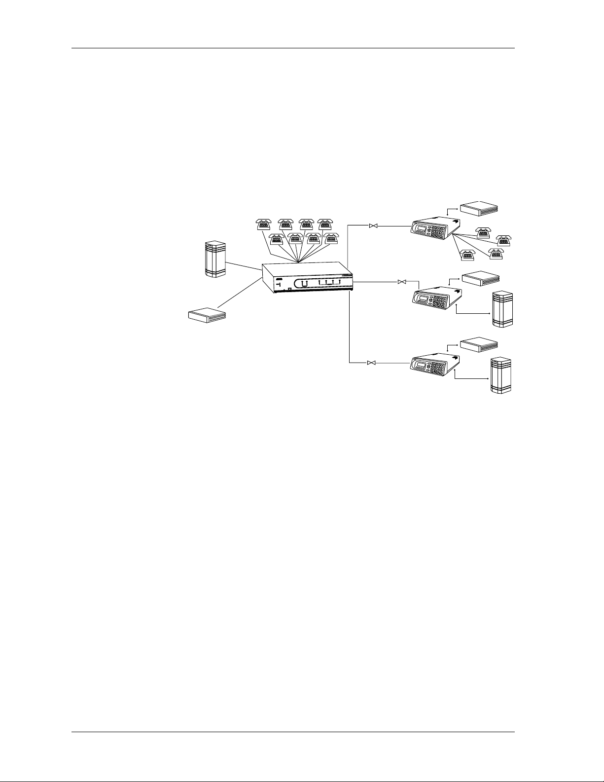
Chapter 1. Introduction
Access Router
As an Access Router, the ATLAS 550 combines the functions of a T1 CSU/
DSU, an intelligent channel bank, a T1 Multiplexer, and DACS into a single
platform. The ATLAS 550 is ideal for point-to-point configurations or access
to public networks. For optimization of existing equipment and network resources, the ATLAS 550 can support a variety of data and analog voice applications (see Figure 1-1 ). The Access Router also supportsawiderange of
data applications including T1 “drop and insert,” channel grooming, and
wide area data transport.
Frame Relay/Router
FracT1
Router
TSU 100e
0
5
5
S
A
L
AT
PBX
4
3
2
1
2
1
S
U
AT
T
S
K
O
K
O
E
N
I
L
N
R
E
W
O
P
M
E
T
S
Y
S
T
E
N
R
E
H
T
E
E
T
O
M
E
R
O
C
A
O
T
S
E
T
T
S
E
T
T
S
E
T
R
O
R
R
E
S
E
L
U
R
D
O
O
R
R
M
E
M
R
A
L
A
M
R
A
L
A
K
R
O
W
T
E
N
T
F
A
R
C
FracT1
Router
ATLAS 550 using
an external router.
Router
FracT1
TSU 100e
PBX
Router
TSU 100e
PBX
Figure 1-1. Point-to-Point Circuit with External Routers
The Frame Relay/Router features enable the Access Router to act as a voice/
dataFRAD, a framerelayswitch,andanIProuter in addition toacting asan
available bandwidth manager and a switch application.
Frame Relay
Frame relay is a packet-switched service that allows efficient transfer of
bursty traffic in a WAN environment. It offers lower-cost data transfer
when compared to typical point-to-point applications. Using virtual connections within the frame relay network and combining those into a single
physical connection at each location result in lower cost. Frame relay providersuseaframerelayswitchtoroutethedataoneachvirtualcircuitto
the appropriate destination. Figures 1-1 and 1-2 illustrate a conversion from
a typical point-to-point application to a frame relayapplication.
1-2 ATLAS 550 User Manual 61200305L1-1
Page 33

Chapter 1. Introduction
FracT1
Router
TSU 100e
PBX
ATLAS 550
R
E
W
O
P
M
E
T
S
Y
S
T
E
N
R
E
H
T
E
E
T
O
M
E
R
T
F
A
R
C
O
C
A
T1
0
5
5
S
A
L
AT
4
3
2
1
2
1
S
U
T
A
T
S
K
O
K
O
E
N
I
L
N
O
T
S
E
T
T
S
E
T
T
S
E
T
R
O
R
R
E
S
E
L
U
R
D
O
O
R
R
M
E
RM
LA
A
M
R
A
L
A
K
R
O
W
T
E
N
Frame
Relay
FracT1
Router
TSU 100e
Router
FracT1
PBX
Router
TSU 100e
PBX
Figure 1-2. Frame Relay Circuit
Router
The ATLAS 550 router uses theEthernet port to transmit local area network
(LAN) traffic over the wide area network (WAN) to a remote LAN. By integrating the router into the network access device, you benefit from the cost
savings of not requiring an external router. Figure 1-1 and Figure 1-3 illustrate a conversion from an application with external routers to one using
integral routers within ADTRAN products.
Access Switch
L
A
N
FracT1
PC
TSU 100e
w/ router module
L
A
N
PC
L
A
N
PBX
PC
PBX
PBX
ATLAS 550
R
E
W
O
P
M
E
T
S
Y
S
T
E
N
R
E
H
T
E
E
T
O
M
E
R
O
C
A
L
A
N
T1
ATLAS550
4
3
2
1
2
1
S
U
AT
T
S
K
O
K
O
E
N
I
L
N
O
T
S
E
T
T
S
E
T
T
S
E
T
R
O
R
R
E
S
E
L
U
R
D
O
O
R
R
M
E
M
R
A
L
A
M
R
A
L
A
K
R
O
W
T
E
N
T
F
A
R
C
Frame
Relay
FracT1
TSU 100e
w/ router module
PC
FracT1
TSU 100e
w/ router module
Figure 1-3. Frame Relay Circuit with Internal Routers
The ATLAS 550 includes an advanced access architecture for switching
dialup calls to specific ports or DS0s. As an access switch functioning in
user-to-user network and user-to-user mode, ATLAS 550 consolidates
multiple basic rate ISDN (BRI) connections onto T1/PRI access lines.
Additionally, BRI-to-BRI, BRI-to-PRI, and PRI-to-PRI switching are
supported. T he ATLAS 550 also converts between ISDN D channel (PRI or
61200305L1-1 ATLAS 550 User Manual 1-3
Page 34

Chapter 1. Introduction
BRI) and T1 Robbed Bit Signaling (RBS) giving you the flexibility to get the
speed and reliability of ISDN, while preserving your investment in nonISDN equipment. AMI and B8ZS line coding provides interoperability with
legacy equipment (see Figure 1-4 ). For network optimization, when
bandwidthis not being used for switched applications such as video
conferencing, switched connection mapping dynamically allocates
bandwidth to the PBX for voice traffic. Call Filtering allows you to program
the call types that will be answered and/or originated on a per-user basis.
T1 RBS D4 AMI
T1 RBS ESF B8ZS
Additional Applications
T1 PRI
T1 PRI
FXS FXS FXS FXS
FXS FXS FXS FXS
POWER
SYSTEM
ETHERNET
REMOTE
ACO
OK
ONLINE
TEST
TEST
ERROR
ALARM
CRAFT
TEST
ERROR
ALARM
NETWORK
MODULES
ATLAS 550
4
3
2
1
2
1
OK
STATUS
BRI
BRI
BRI
BRI
Figure 1-4. The Access Switch
The following sections describe additional applications using the ATLAS
550.
Dedicated and Switched Connection Maps in a Single Platform
The ATLAS550allocatesdedicatedbandwidthaccordingto any of up tofive
unique connection maps. Any DS0 on any T1 circuit can be mapped to any
other DS0 on up to four T1 circuits in the system. Dedicated connection
maps can be manually invoked or automatically implemented based on the
time of day and day of the week.
Additionally, the ATLAS 550 can be configured to switch dialup callsto specific ports or DS0s based on the number that is dialed. Switched connection
mapping is supported fordialupcallsplacedoveranalog/digitalvoicebasic
rate ISDN (BRI) or primary rate ISDN (PRI).
WAN Overbooking
The WAN Overbooking feature of the ATLAS 550 allows you to oversubscribe switched bandwidth for situations where simultaneous access to the
network by every subscriber is not required. WAN Overbooking reduces
telecommunications expenses while still giving your subscriber base the required connectivity. Local subscriber-to-subscriber connections are made
without accessing the network at all, resulting in even more efficient use of
wide area bandwidth.
Digital Access Cross-Connect System (DACS)
Inherent in the ATLAS 550 architecture is the ability to cross connect, or
DACS, four T1circuits. DACSing allows the assignment and redistribution,
orgrooming,ofany DS0onanyT1 circuitto any otherDS0 onanyof thefour
T1 circuits in the system. For optimizing network resources,any of five dedicated connection maps can be invoked manually or automatically, based on
thetimeofdayanddayoftheweek.
1-4 ATLAS 550 User Manual 61200305L1-1
Page 35

Flexible Network Management and Maintainability
Several network management methods are available for the ATLAS 550, including SNMPsupport.VT-100and Telnet are also offered,provingdetailed
system configuration through an easy-to-use menu system. The terminal interface is secured bysix levels of password protection with varying degrees
of management privileges. The terminal interface is accessed locally or remotely by using either the controlport, the CRAFT port, or the Ethernet interface. The Ethernet interface on the Base Unit provides a connection at
10 MBS or 100 MBS.
Userconfigurations can bepreservedinnonvolatilememoryandduplicated
for managing multiple ATLAS 550 implementations. ATLAS 550 also supports flash upgrades for future enhancements. You can remotely download
software using TFTP or XMODEM.
The ATLAS 550 front panel contains an extensive array of LEDs for alarm
and status information pertaining to thesystemandtheindividualmodules.
Several test capabilities allow you to diagnose the health of your T1, PRI, or
BRI circuits without additional test equipment. Tests include local, remote,
and V.54 loopbacks usingthe511,QRSS,allzeros,andallonestestpatterns.
StandardBantamtestjackslocated on the ATLAS 550 networkmodulesalso
allow you to use external test equipment to monitor traffic.
Chapter 1. Introduction
ATLAS 550 FEATURES
Configuration and Management
•VT-100Emulation
• SNMP, per MIB II (RFC1213), DS1 MIB (RFC1406), and ADTRAN private MIBs
•Telnet
• Six levels of password protection and privileges
Software Upgrade
•Flashmemory
•TFTPdownload
•XMODEMviacontrolport
Signaling Support
•ISDNDChannel
• Robbedbit,E&M,GroundStart,LoopStart
• Convert between Robbed Bit Signaling and ISDN D Channel
• Direct Inward Dialing
ISDN Switch Types
• 5ESS™, DMS-100™, National ISDN, 4ESS™
61200305L1-1 ATLAS 550 User Manual 1-5
Page 36

Chapter 1. Introduction
Dedicated Connection Maps
• Up to five connection maps
• Time of day/day of week configurable
• Preserves signaling through cross-connect
• No effect on nonconfigured channels
Switched Connection Maps
• Inbound and outbound call filtering and blocking
Testing
• Local and remote: payload/line, V.54
• Patterns: 511, QRSS, all ones, all zeros
Performance Monitoring
• Reports: Informationstoredfor last 24 hours in 15 minute increments
• Performance statistics per TR54016, T1.403, RFC1406
• Alarm reporting per TR54016, T1.403
Frame Relay/Integral Router
• Routes Internet Protocol (IP)trafficbetweenapublicorprivateframerelay network and the Ethernet port.
• Concentrates IP traffic from a public or private frame relay network to
one or more serial ports (V.35). The protocol passed over the serial port
is frame relay.
• Passes Systems Network Architecture (SNA), Bisync, and other legacy
protocols between a publicor private frame relay networkand an external DTE running frame relay to ATLAS.
• Performs voice compression/decompression (G.723.1) and interfaces to
either a Private Branch Exchange (PBX) or the Public Switched Telephone Network (PSTN). (This feature requires an additional option
module, the VCOM Module—P/N 1200312Lx.)
1-6 ATLAS 550 User Manual 61200305L1-1
Page 37

Chapter 2
Installation
This chapter discussestheinstallation processandtheATLAS550rearpanel
design.
INSPECTING THE ADTRAN SHIPMENT
Before installing the ATLAS 550, carefully inspect the ATLAS 550 Base Unit
for shipping damage. If you suspect damage, file a claim immediately with
the carrier and then contact ADTRAN Technical Support (see the last page
of this manual). If possible, keep the original shipping container for returningtheATLAS550forrepairorforverificationofdamageduringshipment.
Contents of ADTRAN Sh ipments
Your ADTRAN shipment includes the following items:
• The ATLAS 550 Base Unit
•TheATLAS550User Manual
• AC Power cord - ADTRAN P/N 3127031
• Network cable (1) - ADTRAN P/N 3125M008
• Rackmount brackets and screws
• RJ-45—DB-25 adapter (1 for modem connection)
• RJ-45 control port cable (1) - ADTRAN P/N 3127004
• RJ-45—DB-9 adapter (1)
• ADTRAN Utilities diskettes (3)
Customers must supply the Ethernet cable.
61200305L1-1 ATLAS 550 User Manual 2-1
Page 38

Chapter 2. Installation
GROUNDING INSTRUCTIONS
This section provides grounding instruction information from the Underwriters'LaboratoryUL 1950 Standard for Safety of Information Technology
Equipment Including Electrical Business Equipment, of July 28, 1995.
An equipment grounding conductor that isnot smaller in size than the ungrounded branch-circuit supply conductors is to be installed as part of the
circuit that supplies the product or system. Bare, covered, or insulated
grounding conductors are acceptable. Individually covered or insulated
equipment groundingconductors shall have a continuous outer finish that
is either green, or green with one or more yellow stripes. The equipment
grounding conductor is to be connected toground at the service equipment.
The attachment-plug receptacles in the vicinity of the product or system are
all to be of a grounding type, and the equipment grounding conductors serving these receptacles are to be connected to earth ground at the service
equipment.
A supplementary equipment grounding conductor shall be installed between theproductorsystemandgroundthatis in addition to the equipment
grounding conductor in the power supply cord.
The supplementary equipment groundingconductor shall not be smallerin
size than the ungrounded branch-circuit supply conductor s. The supplementary equipmentgrounding conductorshallbeconnectedtotheproduct
at the terminal provided, and shall be connected to ground in a manner that
will retain the ground connection when the product is unplugged from the
receptacle. The connection to ground of the supplementary equipment
grounding conductor shall be in compliance with the rules for terminating
bonding jumpers at Part K or Article 250 of the National Electrical Code,
ANSI/NFPA 70. Termination of the supplementary equipment grounding
conductor is permittedto bemadetobuildingsteel,toametalelectricalraceway system, or to any grounded item that is p ermanently and reliably connected to the electrical service equipment ground.
The supplemental grounding conductor shall be connected to the equipment using a number 8 ring terminal and should be fastenedto the grounding lug provided on the rear panel of the equipment. The ring terminal
should be installed using the appropriate crimping tool (AMP P/N 59250
T-EAD Crimping Tool or equivalent.)
2-2 ATLAS 550 User Manual 61200305L1-1
Page 39

SUPPLYING POWER TO THE UNIT
The AC powered ATLAS 550 comes equipped with a detachable 8-foot power cord with a 3-prong plug for connectingto a grounded powerreceptacle.
As shipped, the ATLAS 550 isset to factory default conditions. After installing the Base Unit and any option modules, the ATLAS 550 is ready for power-up. To power-up the unit, ensure that the unitisproperlyconnectedtoan
appropriate power source and turn on the unit using the on/off switch on
the rear panel.
• This unit shall be installed in accordance with Article 400 and
364.8 of the NEC NFPA 70 when installed outside of a Restricted
Access Location (i.e., central office, behind a locked door, service
personnel only area).
• Power to theATLAS550 must be from a grounded90-240 VAC,
50/60 Hz source.
• The power receptacle uses double-pole, neutral fusing.
• Maximum recommended ambient operating temperature is 40
Chapter 2. Installation
o
C.
MOUNTING OPTIONS
The ATLAS 550 Base Unit may be installed for tabletop,19-inch or 23-inch
rackmount, or wall-mount configuration. ADTRAN includes 19-inch rackmount ears with the Base Unit (23-inch rackmount earsare sold separately).
For a rackmount installation, the ATLAS 550 Base Unit allows flush-face
mount, face-forward mount,center mount, and rearmount. The rackmount
ears may also be turned face down for wall-mounting. When wall-mounted,
the ATLAS 550 Base Unit may be installed with either side up and the front
and rear panelsfacing sideways.
Be careful not to upset the stability of the equipment mounting rack
when installing this product.
REVIEWING THE REAR PANEL DESIGN
The ATLAS 550 rear panel contains four slots for housing option modules
which provide avariety of additional resources and data ports. All slots are
functionally identical. The ATLAS 550 also contains two slots for housing
network interface modules (see Figure 2-1 on page 2-4).
61200305L1-1 ATLAS 550 User Manual 2-3
Page 40

Chapter 2. Installation
Network 1
RJ-48C
Connection
Port
1
2
COVEREDWITH BLANK PANELS
ALLEMPTY SLOTS MUSTBE
T1NETWORK MODULE
Network 1
DB-15
NETWORK 1 NETWORK 2
NETWORK
MON
NETWORK
IN
IN
OUT
OUT
TEST
Bantam
Test Jacks
500Series
Connection
Port
Control/Chain In Port
The Control/Chain In port (EIA-232) connects to a computer or modem or
to another ATLAS 550 Base Unit.Thecontrol port input provides the following functions:
Blank Panel
Covering an
Unused Option Slot
3
4
Blank Panel
Covering an
Unused Network Slot
RJ-48C
Ethernet
10/100BaseT
Connection
Port
Figure 2-1. ATLAS 550 Rear Panel
Supplemental
Earth
Ground Lug
OI
90-240VAC,2A, 50/60Hz
ETHERNET
FUSERATING: 2A/250V SLO-BLO
CONTROL
IN OUT
Control/
Chain
In
Power
Switch
OI
WITHSAME TYPE ANDRATING OF FUSE.
CAUTION:FOR CONTINUED PROTECTION
AGAINSTRISK OF FIRE,REPLACE ONLY
AC P ower
Receptacle
RELAY
ALARM
Alarm Relay
Connection
NCNOCOM
GND
MON
External Alarm Relay
Monitor Connection
Control/
Chain
Out
• Accepts EIA-232 input from a PC or a modem for controlling the ATLAS
550.
• Operates at 2400, 9600, 19200, or 38400 bps.
• Acts as input for either PC control or a chained connection.
• Acts as an interface for flash memory software downloads using
XMODEM.
The Control/Chain In connection follows, and Table 2-1 shows the pinout.
Connector type RJ-48C
Part number AMP# 555164-2
Table 2-1. Control/Chain In Pinout
PIN NAME DESCRIPTION
1 GND Ground - connected to unit chassis
2 RTS Request to send - flow control
3 RXDATA Data received by the ATLAS 550
4 DTR Data terminal ready
5 TXDATA Data transmitted by the ATLAS 550
6 CD Carrier detect
7UNUSED—
8 CTS Cleartosend-flowcontrol
2-4 ATLAS 550 User Manual 61200305L1-1
Page 41

Control/Chain Out Port
TheControl/ChainOutport (RJ-48C)connectstoanother ATLAS550Chain
In connector. The Control/Chain Out port output provides the following:
• EIA-232 output to chain c ontrol to other ADTRAN equipment, such as
a TSU 120.
• 2400, 9600, 19200, or 38400 bps operation
• Automatic setup; no user input required
The Control/Chain Out connection follows, and Table2-2 shows the pinout.
Connector type RJ-48C
Part number AMP# 555164-2
PIN NAME DESCRIPTION
1 GND Ground -connected to unit chassis. Connects to GND
Chapter 2. Installation
Table 2-2. Control/Chain Out Pinout
of next unit.
6,7,8 UNUSED —
Ethernet Co nnection
The Ethernet port (RJ-48C) provides a 10/100BaseT Ethernet LAN connection, which is used for TFTP, SNMP, and Telnet connection. The network
connection follows, and Table 2-3 shows the pinout.
Connector type (USOC) RJ-48C
Part number AMP# 555164-2
2UNUSED—
3 TX DATA Data transmitted to chained units by theATLAS 550.
Connects to RX DATA of the next unit.
4UNUSED—
5 RX DATA Data received from chained units by the ATLAS 550.
Connects to TX DATA of the next unit.
Table 2-3. Ethernet Pinout
PIN NAME DESCRIPTION
1 TX1 Transmit Positive
2 TX2 Transmit Negative
3 RX1 Receive Positive
4, 5, UNUSED —
6 RX2 Receive Negative
7, 8 UNUSED —
61200305L1-1 ATLAS 550 User Manual 2-5
Page 42

Chapter 2. Installation
Alarm Relay Connection
This connection alerts the user when a selected alarm condition exists. The
four-pin, removable terminal block connects with external wiring. To make
the appropriate connections, remove the block, connect wiring as needed,
and return the terminal block to the connector socket. Clear the alarm condition bypressingtheAlarmCut-Off(ACO)switchlocatedonthefontpanel
of the ATLAS 550.
Table 2-4 shows the pinout for the Alarm Relay connector.
Pin Name Description
1 Normally Closed (NC) Opens when a selected alarm condition
After the appropriate connections have beenmade, tighten the
screws using a flathead screwdriver before reinserting the terminal
block into the rear panel of the ATLAS 550.
Table 2-4. Alarm Relay Connector Pinout
is present.
2 Normally Open (NO) Closes when a selected alarm condition
is present.
3 Common (COM) Common connection betweenexternal
circuitry and NC or NO terminal.
4 Chassis Ground (GND)
External Alarm Relay Monitor Connection
This connection alerts the user when a selected external alarmcondition exists. This connection couldbeusedto monitor a UPS with dry contacts or another ATLAS 550.The two-pin, removable terminal block connects with
external wiring. To make the appropriate connections, remove the block,
connect wiring as needed, and return the terminal block to the connector
socket. Clear the alarm conditionby pressing the ACO switch located on the
front panel of the ATLAS 550.
After the appropriate connections have been made, tighten the
screws using a flathead screwdriver before reinserting the terminal
block into the rear panel of the ATLAS 550.
2-6 ATLAS 550 User Manual 61200305L1-1
Page 43

Table 2-5 shows the pinout for the External Alarm Relay connector.
Pin Name Description
Network Connection
The ATLAS 550 provides two Network Interface Slots that allow different
types of interfaces to be used. Currently only a T1 Network Interface is available. In the remainder of this manual, discussions about the Network Interface Module refer to the T1 Network Interface Module. The T1 Network
Interface (NI) port complies with the applicable ANSI and AT&T
dards. The T1 Network Interface Module provides the following functions:
•AMIorB8ZScoding
• Manual line build-out
•D4orESFframing
• Network performance monitoring and reporting
• Test loopbacks with QRSS generation and checking
• Extensive self-testing
Chapter 2. Installation
Table 2-5. External Relay Monitor Connector Pinout
1 Alarm Out Outputs EIA-232 level signal for connection to external
alarm contacts.
2 Alarm In Monitors signal coming from external alarm contacts.
®
stan-
The network connections follow, with the pinouts shown in Table 2-6 and
Table 2-7 on page 2-8.
Connector type (USOC) RJ-48C
Part number AMP# 555164-2
Table 2-6. Network RJ-48C Pinout
PIN NAME DESCRIPTION
1 R1 RXDATA-RING Receive data from the network
2 T1 RXDATA-TIP Receive data from the network
3 UNUSED —
4 R TXDATA-RING Transmit data toward the network
5 T TXDATA-TIP Transmit data toward the network
6, 7, 8 UNUSED —
61200305L1-1 ATLAS 550 User Manual 2-7
Page 44

Chapter 2. Installation
Connector type 15-pin Male D-connector
Part number AMP# 74784-12
Table 2-7. Network Interface 15-pin Male D-connector Pinout
PIN NAME DESCRIPTION
1 T TXDATA-TIP Transmit data toward the network
2 UNUSED
3 T1 RXDATA-TIP Receive data from the network
4, 5, 6, 7 UNUSED
8 FG FRAME GROUND Grounded to chassis
9 R TXDATA-RING Transmit data toward the network
10 UNUSED
11 R1 RXDATA-RING Receive data from the network
12, 13, 14 UNUSED
15 FG FRAME GROUND Grounded to chassis
Test Interface
ETWORKIN
The N
for the incoming T1. Byconnecting test equipment to these jacks, the T1 connection breaksandthetest equipment terminates the incoming T1.TheMON
I
N
and OUTBantam test jacks provide a bridged access jack for nonintrusive
monitoring of the incoming T1. When connected to this jack, configure the
test equipment for bridged termination.
Frame Relay Specifications
• Packet throughput at 4000 pkts/sec
• Management signaling interfaces
- UNI (user-to-network interface)
- NNI (network-to-network interface)
• Management signaling types
- ANSI T 1.617-D (Annex D)
- ITU-T Q.933-A (Annex A)
- LMI (Group of four)
-Auto
• Encapsulation - RFC 1490 for IP andLLC2
• PVC support - 300 PVCs
and OUTBantam test jacks provide intrusive test capability
2-8 ATLAS 550 User Manual 61200305L1-1
Page 45

• Congestion control
- FECN / BECN
- Discard eligible (DE)
• Quality of service (QOS) - Prioritization on a per-PVC basis
• Testing (ADTRAN proprietary)
-PVCloopback
- Round trip delay measurement
• SNMP support -RFC 1315
IP Router Specifications
• Route discovery
-RIPV1
-RIPV2
-ICMP
-ARP
-IARP
-UDPRelay
• Virtual connections supported - 100 PVCs
• SNMP support - MIB II
Chapter 2. Installation
Option Slots
Figure 2-2 showsthe option slot numberingdesignation as viewed from the
rear of the ATLAS 550. The functionally identical option slots only accept
ATLAS 550 option modules.
SLOT 1
SLOT 2
Network Slot 1
Figure 2-2. ATLAS 550 Slot Designation (Rear Panel)
INSTALLING OPTION MODULES
After installing the ATLAS 550 Base Unit and connecting the required cables, you can install your choice of option modules. Instructions for installing option modules are given in the user manuals for the chosen modules.
SLOT 3
SLOT 4
Network Slot 2
61200305L1-1 ATLAS 550 User Manual 2-9
Page 46

Chapter 2. Installation
2-10 ATLAS 550 UserManual 61200305L1-1
Page 47

Chapter 3
Operation
OVERVIEW
To fully operate the ATLAS 550, you must connect to theterminalmenususing VT-100 terminal emulation or a Telnet session. The following sections
provide an overview of these methods of operating the ATLAS 550.
USING THE TERMINAL MENUS
The terminal menu provides the primary means of monitoring and configuring the ATLAS 550. The terminal menu interface uses the full capabilities
of the VT-100 terminal to provide the quickest and most intuitive operation
possible. (AccesstheterminalmenubyusingaVT-100 terminal or acomputer running VT-100 terminal-emulation software.) To receive the full benefit
of the terminal menu interface, you should use a fully VT-100compatible client. TheADTRANUtilitiesfloppydisks (thatyoucan install onaPC)contain
both a VT-100 client and a customized Telnet program. See ADTRAN Utili-
ties on page 14-1 for details on the available programs.
The three basic connection methods supported by the ATLAS 550 are a direct connection through the EIA-232 Control/Chain In port (located on the
rear panel),adirectconnectionthroughthe EIA-232CRAFTport(locatedon
the front panel), and a Telnet session. The following sections describe using
VT-100 terminal emulation (for either of the two EIA-232 ports) and establishing a Telnet session.
Using VT-100 Terminal Emulation
You can accessthe ATLAS 550 terminalmenu, using VT-100 terminal emulation, from either the Control/Chain In port on the rear panel or the CRAFT
port on the front panel. Both of theseportsprovidean EIA-232 serial connection. The following Step/Action table provides instructions for setting up
the ATLAS 550 for VT-100 terminal mode.
61200305L1-1 ATLAS 550 User Manual 3-1
Page 48

Chapter 3. Operation
Instructions for Setting Up an ATLAS 550 for VT-100 Terminal Mode
Step Action
1 Set the baud rate on the VT-100 terminal to 9600 baud (8/N/1).
Use the ADTRAN-provided VT-100 terminal adapter to connect
the COM port of a VT-100 compatible terminal, or equivalent, to
the eight-pin modular jack labeled
2
CONTROL/CHAIN IN
on the
rear panel or labeled CRAFT on the front panel.
This connection provides both local and remote configuration.
Press Enter repeatedlyon thekeyboard until the L
3
requiring a password appears.
OGIN
menu
4 Press Ctrl-R to refresh the display, if necessary.
When you begin the VT-100 session, you will be prompted for a password.
The default password is password (which is a Level 0 superuser password).
You can change this password using the A
CCESSPASSWORDS
option, which
is only accessible through the terminal menu. See Access Passwords on page
6-15 for details. After your password is accepted, define the IP Address of
the ATLAS 550 to which you want to connect. The following Step/Action
chart describes this process.
Instructions for Defining the IP Address
Step Action
Obtain an IP address f or the ATLAS 550 from your LAN
1
administrator.
Use the ADTRAN-provided VT-100 terminal adapter to connect
the COM port of a VT-100 compatible terminal, or equivalent, to
the eight-pin modular jack labeled CONTROL/CHAIN IN on the
2
rear panel or labeled CRAFT on the front panel.
This connection provides both local and remote configuration.
Press Enter repeatedlyon thekeyboard until the L
3
appears. Enter y our password.
When the terminal menu opens, navigate thefollowing path:
4
ATLAS 550 /S
YSTEMCONFIG/ETHERNET PORT
OGIN
/IPA
menu
DDRESS
5 Key in the entire IP address, and then press Enter.
You will need a default gateway if the LAN contains multiple
segments. Contact your LAN administrator for the appropriate
address.
3-2 ATLAS 550 User Manual 61200305L1-1
Page 49

USING TELNET
Starting a Telnet Session
Chapter 3. Operation
To connect to the ATLAS 550 via Telnet, you must define the IP address, set
the subnet mask, and, typically, set the default gateway IP address.
You must define the IP address before attempting to connect via
Telnet. See Using VT-100 Terminal Emulation on page 3-1 for
details on defining the IP address.
You will need a default gateway if the LAN contains multiple
segments. Contact your LAN administrator for the appropriate
address.
When you begin the Telnet session, you will be prompted for a password.
The default password is password (which is a Level 0 superuser password).
You can change this password using the A
CCESSPASSWORDS
option, which
is only accessible through theterminal menus. See AccessPasswordson page
6-15 for details. The Telnet session will time out and display the Login
prompt after apredefinedtimethatissetinthe S
ESSIONTIMEOUT
option(see
Session Timeout on page 6-9 for details).
Use the MAXT
ELNETSESSIONS
option to define the number of
Telnet sessions that can be active at one time (see Max Telnet
Sessions on page 6-9 for details).
Microsoft Telnet version 1.0 does not implement full VT-100
emulation. However, many commercial Telnet clients for Microsoft
Windows exist which fully implement VT-100. In addition, a
freeware client, recommended foroptimum performance, comes with
the ATLAS 550. See VT-100 Utility on page 14-8 for details.
61200305L1-1 ATLAS 550 User Manual 3-3
Page 50

Chapter 3. Operation
3-4 ATLAS 550 User Manual 61200305L1-1
Page 51

Chapter 4
OVERVIEW
Using the Front Panel
The front panel contains the AlarmCut-off (ACO) switch, the CRAFT port,
and the controller and module status LEDs. The LEDs provide visual information about the ATLAS 550 BaseUnitand any option module that may be
installed. Figure 4-1 identifies the ACO switch, the CRAFT port, and the
LEDs.
POWER
SYSTEM
ETHERNET
REMOTE
ACO
Controller
Status
LEDs
Alarm
Cut-off
Switch
ACO SWITCH
CRAFT
Port
Network Module
Status LEDs
1 2
OK
TEST
TEST
ERROR
ERROR
ALARM
ALARM
NETWORK
1 2 3 4
OK
STATUS
ONLINE
TEST
Option Module
Slot Numbers
Module Status LEDsCRAFT
MODULES
Figure 4-1. ATLAS 550 Front Panel Layout
The ACO switch deactivates (clears) the Alarm Relay, located on the rear
panel of the ATLAS 550, after an alarm condition has occurred.If an alarm
condition is corrected and then reoccurs, the Alarm Relay will re-energize
(see also ACO Switch in Table 4-2 on page 4-3).
ATLAS 550
61200305L1-1 ATLAS 550 User Manual 4-1
Page 52

Chapter 4. Using the Front Panel
CRAFT PORT
Use the CRAFT port to configurethesystemviaanEIA-232connection.The
CRAFT port provides the same functions and operations as the Control In
port located on the rear panel of the ATLAS 550. The connector type is
shown below, and Table 4-1 gives the CRAFT port pinout (see also CRAFT
Port on page 4-3 in Table 4-2).
Connector type RJ-48C
Part number AMP# 555164-2
Table 4-1. CRAFT Port Pinout
PIN NAME DESCRIPTION
1 GND Ground - connected to unit chassis
2 RTS Request to send - flow control
3 RXDATA Data received by the ATLAS 550
4 DTR Data terminal ready
FRONT PANEL L ED S
With the ATLAS 550 powered-up, the front panel LEDs provide visual information about the status of the ATLAS 550 and any option modules that
may be installed. Table 4-2 on page 4-3 provides a brief description of the
front panel features, and Table 4-3 on page 4-4 provides detailed information about the LEDs.
5 TXDATA Data transmitted by the ATLAS 550
6 CD Carrier detect
7UNUSED —
8 CTS Clear to send - flow control
4-2 ATLAS 550 User Manual 61200305L1-1
Page 53

Chapter 4. Using theFront Panel
Table 4-2. ATLAS 550 Front Panel Description
Feature Description
Controller Status LEDs Displays thegeneral status of the entire ATLAS 550. (See also Table4-3
on page 4-4.)
Power Indicates the unit is on or off.
System Indicates the status of the system.
Ethernet Indicates the status of the ethernet port.
Remote Indicates whether a user is logged into the unit.
Network Module LEDs Displays the status of the network interface. (See also Table 4-3.) All
LEDs are off if no network module isinstalled.
OK Indicates that the network interface is operating correctly.
Test Indicates that the network interface is in a test mode.
Error Blinks to indicate the occurrence of error events.
Alarm Indicates an alarm condition on the network interface.
Option Module LEDs Displaysby row the operational condition of each module installed in the
option slots. (See also Table 4-3 on page 4-4.) All LEDs will be off if no
option module is installed.
Status Indicates the operational condition of modules installed in the option
slots.
Online Indicates whether the module isavailablefor use or is currently in use.If
the module is manually taken offline, this LED is turned off.
Test Indicates that one or more ports within a module are in test.
ACO Switch Clears the Alarm Relay connection located on the rear panel of the
ATLAS 550.
CRAFT Port Allows the ATLAS 550 to connect to a computer or modem using the
CRAFT port (an EIA-232 port).
61200305L1-1 ATLAS 550 User Manual 4-3
Page 54

Chapter 4. Using the Front Panel
Table 4-3. ATLAS 550 LEDs
For these LEDs... This color l ight... Indicates that...
Power Green The unit is on.
Off The unit is off.
Ethernet Green (solid) Physical link is up.
Green (flashing) Indicates activity on the LAN.
Off Physical link is down - no Ethernet connection.
Remote Yellow Indicates a user is logged in the system via Control/
Craft port or via Ethernet.
Off No one is logged into the system.
System Green (solid) No diagnosed system faults were found.
Green (fast blink) Flash download is in progress.
Yellow (solid) A fault was diagnosed, but the condition no longer
exists. The condition will be recorded in the system
log.
Network Module
Status
Red (solid) An error condition with either the power supply or the
temperature is present.
Red (fast blink) A fatal error occurred during flash download.
Off P ower is not currently supplied to the system.
OK (green) The network interface is operating normally with error-
free operation. If the interface experiences alarms, the
OK LED remains off.
Test (yellow) The interface is operating in a test mode. Thisincludes
a self-test, a test pattern, or a test loopback. When
illuminated, this LED also indicates that normal data
flow is not occurring in the module ports.
Error (flashing red) Indicates an error such as BPV (bipolar violation),
OOF (out of frame), or CRC (cyclic redundancy
check).
Alarm (red) An alarm condition has been detected. When the
alarm condition is no longer valid, the OK LED
illuminates. To view an alar m condition, select the
active alarm menu item. If the alarm conditions have
been corrected, you can view the alarm which caused
the activation of the A
LARM
LED in the system log.
4-4 ATLAS 550 User Manual 61200305L1-1
Page 55

Chapter 4. Using theFront Panel
Table 4-3. ATLAS 550 LEDs (Continued)
For these LEDs... This color light... Indicates that...
Module Status Green (solid) One or both modules (in the case of a Resource
Module) are OK.
Green (fast blink) • One or both modules (in the case of a Resource
Module) have been set offline by the user.
• One or both modules (in the case of a Resource
Module) have invalid flash memory.
Green (slow blink) One module has been set offline or has invalid flash
memory.
Red (solid) One module failed its selftest.
Red (fast blink) One module has no response, has been removed, or
is not supported.
Red (slow blink) One module is not ready.
Off No module occupies the slot.
Module Online Green (solid) One or both modules (in the case of a Resource
Module) have an active connection.
Green (fast blink) One module has invalid flash memory or is
downloading firmware.
Green (slow blink) Only one module has an active connection.
Module Test Yellow (solid) One module is in a test mode.
61200305L1-1 ATLAS 550 User Manual 4-5
Page 56

Chapter 4. Using the Front Panel
4-6 ATLAS 550 User Manual 61200305L1-1
Page 57

Chapter 5
Navigating the Terminal Menus
TERMINAL MENUS WINDOW
The ATLAS 550 uses a multilevel menu structure that contains both menu
items and data fields. All menuitemsand data fields display in the term inal
menu window, through which youhavecomplete control oftheATLAS 550
(see Figure 5-1).
Menu Path
Sys
Slot Status
Tool Tip
Viewing the Menus
You can view the terminal menu in two ways: with fields and submenus displaying horizontally across the right pane or with fields and submenus displaying vertically downthe right pane. Viewing submenus vertically rather
than horizontally allows you to see information at a glance rather than
scrolling horizontally across the window. To change the view, move your
cursor to an index number and press
modules, move the cursor up and down overthe list ofmodules. Figure 5-2
on page 5-2 shows the two views for the M
Extended
Help
Figure 5-1. Top-level Terminal Menu Window
. Toviewinformationabout other
Enter
ODULES
Field and submenu names may vary slightly in the twoviews.
Navigation
Help
menu.
System
Time
61200305L1-1 ATLAS 550 User Manual 5-1
Page 58
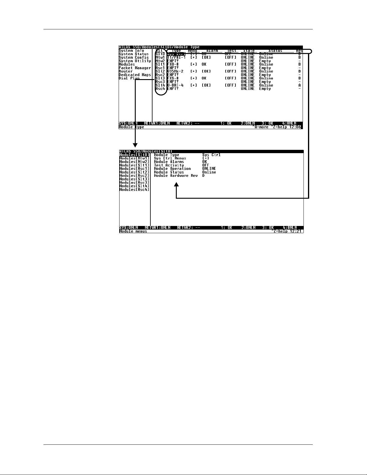
Chapter 5. Navigating the Terminal Menus
Slots Display in
Left Pane
Menu Path
Window Panes
Fields and Submenus Display
In Vertical List
(Note change in names.)
Figure 5-2. Two Views of the Same Menu
The top line of the terminal menu window, the menu path, showsthe session’s current position (path) in the menu structure. For example, in Figure
5-1 on page 5-1 the cursor is on the S
ULES
menu; therefore, the menu path reads ATLAS 550/M
ODULETYPE
M
.
LOT0MODULETYPE
field of the M
ODULES[SLOT
OD
0]/
When you first start a terminal menu session, the terminal menu window is
divided into left and right panes. The left pane shows the list of available
submenus, while the right pane shows the contents ofthe currently selected
submenu.
-
Window Pane Navigation
Use the followingcharttoassist you in moving betweenandwithinthetwo
window panes.
5-2 ATLAS 550 User Manual 61200305L1-1
Page 59

To move... Press one of these keys...
From left pane to right pane Tab
From rightpane to left pane Tab
Within each pane Up arrow
Right Window Pane Notation
The right window pane shows the contents of the currently selected menu.
These contents can include both submenu items and data fields. Some submenuscontainadditionalsubmenusandsomedatafields containadditional
data fields. The following chart explains the notation used to identify these
additional items.
Chapter 5. Navigating the Terminal Menus
Enter
Left arrow
Right arrow
Escape
Left arrow
Right arrow
Down arrow
Left arrow
Right arrow
This notation... Means that...
[+] More items are available when selected.
[DATA] More items are available when selected.
<+> An action is to be taken, such as activating a test.
Highlighted menu item You can enter data in this field.
Underlined field The field contains read-only information.
Additional Terminal Menu Window Features
The following features are located across the bottom of the window:
Sys
Describes the status of the ATLAS 550 base unit.
Tool Tip
Provides a brief description of the currently selected (highlighted) field.
Slot Status
Displays status information, such as OK, WARN (warning), or ALRM
(alarm), about slots 1 through 4.
61200305L1-1 ATLAS 550 User Manual 5-3
Page 60

Chapter 5. Navigating the Terminal Menus
Extended Help
) Displays information about selected commands (see Figure 5-3).
Ctrl-A
(
Navigation Help
(
) Lists characters used for navigating the terminal menu (see Figure 5-
Ctrl-Z
4). See also the section, Moving through the Menus on page 5-5.
Figure 5-3. Sample Extended Help Window
Figure 5-4. Navigation Help Window
System Time
Displays the current time. See CurrentTime/Date(24h) on page 6-3 for details
on editing the time.
NAVIGATING USING THE KEYBOARD KEYS
You can use various keystrokes to move through the terminal menu, to manage a terminal menu session, and to configure the system. Press
tivate a pop-up screen listing the navigation keystrokes.
Ctrl-Z
to ac-
5-4 ATLAS 550 User Manual 61200305L1-1
Page 61

Chapter 5. Navigating the Terminal Menus
Moving through the Menus
To do this... Press this key...
Return to the home screen. H
Jump between two menu items.
Press
the main screen.
Go to another menu item, press
displayed the first time you pressed
PressJanytime you want to jump between these items.
Select items. Arrows
Edit a selected menu item. Enter
Cancel an edit. Escape
Close pop-up help screens. Escape
Move between the left and right panes. Tab
Move to the top of a screen. A
Move to the bottom of a screen. Z
Ascend one menu level. Backspace
while the cursor is located on a menu item, and you jump back to
J
, and you jump back to thescreen thatwas
J
J.
J
Arrows
Session Management Keystrokes
To do this... Press this...
Log out of a session. Ctrl-L
Invalidate the password entry and return to the login screen. Ctrl-S
Refresh the screen.
To save time, only the portion of the screen that has changed is
refreshed. This option should only benecessary if the display picks up
incorrect characters.
61200305L1-1 ATLAS 550 User Manual 5-5
Ctrl-R
Page 62

Chapter 5. Navigating the Terminal Menus
Configuration Keystrokes
To do this... Press this key...
Restore factory default settings.
This setting restores the factory defaults based on the locationof the cursor. If
thecursorisonamoduleline(intheM
ODULES
menu), then only the selected
module is updated to factory defaults.
Copy selected items to the clipboard.
The amount of information you can copy depends on the cursor location when
you press
:
C
If the cursor is over an editable field, only that item is copied.
If the cursor is over the index number of a list, then all of the items in the row
of the list are copied. For example, if the cursor is over the S
the M
ODULES
screen, all of the information associated with the slot is
LOT
# field in
copied.
Paste the item stored on the clipboard.
Information to be pasted must be compatible with the intended field.You
must confirm all pastes—except those to a single editable field.
Increment the value of certain types of fields by one, when you paste
information into those fields.
Decrement the value of certain types of fields by one, when you paste
information into those fields.
F
C
P
>
<
Insert a new list item.
Forexample,toaddanewitemtotheD
while the cursor is on an index number.
I
Delete a list item.
For example, to delete an item from the D
press
while the index number is active (highlighted).
D
Getting Help
The bottom line of the terminal menu window contains context-sensitive
help information. When the cursor is positioned over a set of configuration
items, a help message (tool tip) displays, when available, providing a description of the set. If more detailed help is available for a particular field,
displaysat the bottomofthe window. Whenyoupress
screen displays additional information a bout the field.
Press
Ctrl-Z
ing the terminal menu.
I
EDICATEDMAP
connection list, press
D
EDICATEDMAP
connection list,
Ctrl-A,
^A
apop-uphelp
to activate a help screen that displays thekeystrokes for navigat-
5-6 ATLAS 550 User Manual 61200305L1-1
Page 63

Chapter 6
System Control Terminal Menus
OVERVIEW
The terminal menu is the access point to all other operations. Each terminal
menu item hasseveralfunctionsandsubmenusthatidentifyandprovideaccess to specific operations and parameters. Use the chart below to help you
select the appropriate terminal menu.
To do this... Go to this menu...
Review and monitor general system information for the ATLAS 550.
Review and monitor system status for the ATLAS 550.
Set up the operational configurationfor the ATLAS550.
Update settings, transfer files, perform system diagnostics, and
reboot the ATLAS 550.
Review and configure settings for each installed module, including
the ATLAS 550 Base Unit.
Define and configure all layer 2connections includingFrame Relay
endpoints.
Define, configure, and monitor all ATLAS 550 Router functions.
Assign dedicated connections between any two ports in the
ATLAS 550.
Set global ATLAS 550 switch parameters or set individual
parameters for each port in ATLAS 550 that handles a switched
call.
System Info
System Status
System Config
System Utility
Modules
Pac ket Manager
Router
Dedicated Maps
Dial Plan
on page 6-2.
on page 6-17.
on page 7-1.
on page 9-1.
on page 11-1.
on page 6-3.
on page 6-8.
on page 8-1.
on page 10-1.
61200305L1-1 ATLAS 550 User Manual 6-1
Page 64

Chapter 6. System Control TerminalMenus
SECURITY LEVELS
Toeditterminalmenuitems,youmusthaveapasswordandthe appropriate
securitylevel.Table 6-1 describes thesixsecuritylevels.See Access Passwords
on page 6-15 for additional information on working with passwords.
Security Level Description
5 Read-only permission for all menu items—minimum
4 Read permission for all menu items and permission to
3 Access to all commands except passwords, flash
2 Access to all commands except passwords, flash
1 Access to all commands except passwords.
Table 6-1. Password Security Levels
rights.
use test commands.
download, authentication methods, and interface
configurations.
download, and authentication methods.
S
YSTEMINFO
0 Permission to edit every menu item, including creating
and editing passwords—maximum rights.
YSTEMINFO
The S
data fields for editing information. Figure 6-1 displays the submenus that
are available when you select this menu item.
menu provides basic information about theunit as well as
Figure 6-1. System Information Menu
SYSTEM NAME
6-2 ATLAS 550 User Manual 61200305L1-1
Write security: 3; Read security: 5
Providesa user-configurable text string for the name of the ATLAS 550.
This name can help you distinguish between differentinstallations. You can
enter up to 40 alpha-numeric characters in this field, including spaces and
special characters (such as an underbar).
Page 65

Chapter 6. System Control Terminal Menus
SYSTEM LOCATION
SYSTEM CONTACT
FIRMWARE REVISION
SYSTEM UPTIME
STARTUP MODE
Write security: 3; Read security:5
Provides a user-configurable text string for the location of the ATLAS 550.
This field is to help you keep track of the actual physical location of the
unit. You can enter up to 40 alphanumeric characters in this field, including
spaces and special characters (such as an underbar).
Write security: 3; Read security: 5
Provides a user-configurable text string for a contact name. You can use this
field to enter the name, phone number,or email address of a person responsible for the ATLAS 550 system. You can enter up to 40 alpha-numeric characters in this field, including spaces and special characters (such as an
underbar).
Read security: 5
Displays the current firmware revision level of the controller.
Read security: 5
Displays the length of time the ATLAS 550 system has been running. Each
time you reset the system, this value resets to 0days, 0 hours, 0 minutes and
0seconds.
Read security: 5
Displays details about the last system startup.
CURRENTTIME/DATE
(24H)
INSTALLED MEMORY
SERIAL NUMBER
BOOT ROM REV
S
YSTEMSTATUS
Write security: 3; Read security: 5
Displays the current date and time, including
seconds. To edit this field, place the cursor on the
field and press
24-hour format (such as 23:25:30 for 11:00 pm, 25 minutes and 30 seconds),
and the date in mm-dd-yyyy format (for example, 11-05-1999). Press
when you are finished.
Read security: 5
Displays the type and amount of memory in use (including Flash memory
and DRAM).
Read security: 5
Displays the serial number for the unit. The serial number of the
ATLAS 550 will automatically display in this field.
Read security: 5
Displays the boot ROM revision.
YSTEMSTATUS
The S
Figure6-2on page 6-4 showsthesubmenu functionsavailableintheS
TATUS
S
menu.
. Then, enter the time in a
Enter
menu provides information on the status of the unit.
Enter
YSTEM
61200305L1-1 ATLAS 550 User Manual 6-3
Page 66

Chapter 6. System Control TerminalMenus
Figure 6-2. System Status Menu
EVENT LOG
IME
T
AT
C
RC
S
LOT
S
ORT
P
Read security: 5
Displays the last 350 warning or failure messages sent—including the day,
date, and priority of the message. The most recent messages display at the
top of the list. The following read-only fields are available to review:
Displaysthe date (inmm/ddformat) and thetime(in hh:mm:ssformat)that
the event occurred.
Category(CAT) displays theseverityoftheevent.Thepossible categories are
RITICAL
C
which types of errors you want the system to log with the E
, M
AJOR
, M
INOR
, W
ARNING
, N
ORMAL
,andI
NFO
. You can specify
VENTLOGGING
option. See Event Logging on page 6-14 for details.
Displays the type of event.
Displays the slot numberinwhich the event occurred. If thisfield displays a
dash (-), the event occurred in the ATLA S550 base unit.
Displays the port in which the event occurred.
VENT
E
ESCRIPTION
D
6-4 ATLAS 550 User Manual 61200305L1-1
Displays a description of the event.
Page 67

Chapter 6. System Control Terminal Menus
CLEAR SYSTEM
EVENT LOG
ETHERNET PORT
Write security: 3; Read security: 5
Clears the event log. When you select the command, the followingprompt
displays: This will clear the entire event log. Confirm (y/n). Select
log or
Read security: 5
Displays status information about the Ethernet port. An asterisk (*) indicates activity for the item. The following read-only fields are available to
review:
I/F S
T
R
to exit the command.
N
If you clear the event log, you cannot retrieve the data.
TATUS
XFRAMES
XFRAMES
Indicates the current status of the Ethernet port.
Indicates the number of frames transmitted from the
Ethernet port since system startup.
Indicates the number of frames received on the Ethernet
port since system startup.
to clear the
Y
CLEAR SYSTEM LED
SYSTEM
TEMPERATURE
ALARMS
SYSTEM POWER
ALARMS
SYSTEM TIMING
SOURCE
THERNETRATE
E
Write security: 3; Read security: 5
Changes the color of the system LED on the front panel from yellow (indicating a previous error) to green (OK). The system LED turns red if the
ATLAS 550 detects a major system failure. If the failure condition clears, the
LEDturnsyellowandremainsyellowtowarnofthepastfailure.
Read security: 5
Indicates that the internal temperature of the unit has
exceeded normal operating limits. The two thresholds
indicate that the internal temperature is greater than 70
o
than 85
in the Event Log but no other action will be taken.
Read security: 5
Indicates that the -58 V and/or -24 V power supplies
are not functional. These power supplies are continuously monitored to determine failures. If one of these supplies fails, a message will be placed in the E
Read security: 5
Indicates which timing source (primary or backup) is currently being used
by ATLAS 550 and if ATLAS 550 is locked onto thissource. If the display
does not indicate locked, the ATLAS 550 does not have a valid source of
timing and cannot reliably transfer data. Review the current setting for system timing source in the S
on page 6-8 and Backup Timing Source on page 6-8 for details.
C. If one of these thresholds is exceeded, a warning will be placed
Indicates the data rate on the Ethernet port.
o
Cand/orgreater
VENTLOG
YSTEMCONFIG
(see also Event Log on page 6-4).
menu. See Primary Timing Source
61200305L1-1 ATLAS 550 User Manual 6-5
Page 68

Chapter 6. System Control TerminalMenus
RESOURCE USAGE
ATATABLES
D
Read security: 5
Indicates resource use (ANALOG
IGITAL
D
). Data displayed in this table is dependent on the Atlas 550 configu-
AILEDDIGITAL
, N
ACKETVOICE
, P
WITCHED
, S
ration.
One HDLC resource is used by each PRI or each Packet Endpoint.
Tracks resource usage for dynamic resources throughout the system and
presents the information in a table format.
ESOURCETYPE
R
Displays the system resources list.
URRENT
C
Shows the number of resources available (not in use) and the total number
of resources. If a resource is taken offline, it is not included in the total.
VERAGE
A
Shows the average number of resources available since the stati stics were
last reset.
ONFIGURATION
C
INIMUM
M
Shows the fewest number of resources availablesince the last reset.
ZERO)AVAILABLE
0(
Provides a count of the number of times the quantity of available resources
reached 0.
OURLYDATA
H
Shows availability information by hour for a 24-hour period.
ESET
R
Write security: 4; Read security: 5
Activates the reset of all accumulated availability statistics.
Configures the statistics displayed under data tables.
ISPLAYFORMT
D
Selects the statistics displayformat—R
ESETMODE
R
AWDATA
or %.
Write security: 4; Read security: 5
Selects the mode for resetting statistics—MA NUAL
, D
AILY
,orW
EEKLY
.
6-6 ATLAS 550 User Manual 61200305L1-1
Page 69

Chapter 6. System Control Terminal Menus
RUNKUSAGE
T
Read security: 5
Indicates trunk use:
(N
ETTERM
ATATABLES
D
PRI, NETT
ERM
RBS; U
SERTERM
PRI, U
SERTERM
RBS).
T racks resource usage for dynamic resources throughout the system and
presents the information in a table format.
RUNKTYPE
T
URRENT
C
Displays the system trunk list.
Shows the number of trunks available (not in use) and
the total number of trunks. If a trunk is taken offline, it
is not included in the total.
VERAGE
A
Shows the average number of trunks availablesincethe
statistics were last reset.
INIMUM
M
Shows the fewest number of trunks available since the
last reset.
ZERO
0(
AVAILABLE
S
R
)
LT/PRT
ESET
Providesa countof the numberof timesthequantityof
available trunks reached 0.
Displays data tables for a specific port.
Write security: 4, Read security: 5
Resets all accumulated availability statistics.
CHAIN PORT SIGNAL
LEADS
CHAIN PORT TX
BYTES
ONFIGURATION
C
Configures the statistics displayed under data tables.
ISPLAYFORMT
D
ESETMODE
R
Selects the statistics display format—R
Write security: 4; Read security: 5
Selects the mode for resetting statistics—MANUAL
D
AILY
,orW
EEKLY
.
AWDATA
or %.
,
Read security: 5
Displays the state of the following options (these fields are read-only). An
asterisk (*) indicates activity for the item.
RTS Request to send.
CTS Clear to send.
DTR Data terminal ready.
DCD Data carrier detect.
Read security: 5
Displays the number of transmitted data bytes.
61200305L1-1 ATLAS 550 User Manual 6-7
Page 70

Chapter 6. System Control TerminalMenus
CHAIN PORT RX
BYTES
CHAIN PORT
OVERRUN ERRS
CHAIN PORT
FRAMING ERRS
CLEAR CHAIN PORT
COUNTRS
S
YSTEMCONFIG
Read security: 5
Displays the number of received data bytes.
Read security: 5
Displays the number of overrun errors.
Read security: 5
Displays the number of received framing errors.
Clears all chain port counters. Press Y to activate this command.
YSTEMCONFIG
The S
configuration. Figure 6-3 shows the items included in this menu.
menu allows you to set up the ATLAS 550 operational
PRIMARY TIMING
SOURCE
BACKUP TIMING
SOURCE
ADLP ADDRESS
Figure 6-3. System Configuration Menu
Write security: 3; Read security: 5
Selects the primary timing source. Select
either
INTERNAL
installed modules.
Write security: 3; Read security: 5
Selects the secondary timing source. You can select either
port from one of the installed modules. ATLAS 550 uses the backup timing
source if the primary timing source goes into alarm. The B
OURCE
S
Write security: 2; Read security: 5
Shows the system ADTRANData Link Layer Protocol (ADLP) address for
connecting remote devices to managementsoftware.The allowable range is
between 2 and 65520. Enter a value not used by any other ADTRAN units
controlled by the management software.
should be different from the P
or a port from one of the
RIMARYTIMINGSOURCE
INTERNAL
ACKUPTIMING
or a
.
6-8 ATLAS 550 User Manual 61200305L1-1
Page 71

Chapter 6. System Control Terminal Menus
SESSION TIMEOUT
MAX TELNET
SESSIONS
ETHERNET PORT
ORTNAME
P
DDRESS
IP A
Write security: 3; Read security: 5
Definesthenumberofsecondstheterminal sessionmustremain idle before
the session times out. You can enter zero to deactivate this option (the session will never time out).
Write security: 3; Read security: 5
Defines the maximum number of Telnet sessions that can be active at the
same time. Enter a number between 0 and 100 in this field.
If you enter zeroin this field, you will not be ableto use Telnet. Only
enter zero if you want to completely lock outTelnet access.
Write security: 2; Read security: 5
Provides a way to configure various settings for the Ethernet port. The following options are available for review and editing:
Defines the name of the Ethernet port. You can leave this field blank.
Lists the address assigned to the base Ethernet port. This address is composed of four decimal numbers, each in the range of 0 to 255, separated by
periods. This value is set to 0.0.0.0 by default.The IP address is usedfor the
Ethernet interface. Obtain the correct IP address from your LAN administrator.
D
EFAULT
ATEWAY
G
S
UBNETMASK
MAC A
DDRESS
Defines or changes the default gateway. Enter the default gateway address
by entering a decimal number into the appropriate field and then pressing
to move to the next field. You will need a default gateway if the LAN
Enter
containsmultiplesegments.Thisaddressiscomposedoffourdecimalnumbers, each in the range of 0 to 255, separated by periods. This value is set to
0.0.0.0 by default. Contact your LAN administrator for theappropriate address.
Defineswhichpartof a destinationIPaddress containsthe networknumber.
This address is composed of four decimal numbers, eachinthe range of 0 to
255, separated by periods. Thisvalue is set to 0.0.0.0 by default. This part of
the destination IP address is used along with the ATLAS 550 IP address to
determine which nodes must be reached through the default IP gateway.
Displays the system Ethernet Media Access Control (MAC) address. This
field is read-only.
61200305L1-1 ATLAS 550 User Manual 6-9
Page 72

Chapter 6. System Control TerminalMenus
THERNET
E
PEED
S
CHAIN PORT
ORTNAME
P
ORTTYPE
P
ORTSPEED
P
Write security: 3; Read security:5
Defines the data rate on the Ethernet interface. Choose from 10 M
UTO
10/100. Whenthe unit is set for A
A
UTO
10/100 the ATLAS 550 auto
detects the data rate of the LAN and set itself to that rate, either10 M
BPS
100 M
.
BPS
or
BPS
or
Write security: 2; Read security: 5
Accepts input for configuring the ChainIn port.
Write security: 2; Read security: 5
Definesthenameofthechainport. Typeinanalpha-numeric name up to 57
characters long. The name can include spaces and special characters.
Write security: 2; Read security: 5
Specifieswhether you use DIRECT
or D
IAL
mode.
Write security: 2; Read security: 5
Specifies the baud rate of the port. Select either 2400, 9600, 19200,or 38400.
If you are using D
IAL
for P
ORTTYPE
, ensure that the P
ORTSPEED
setting
matches the modem baud rate.
SNMP
ODEM
M
NITIALIZATION
I
TRING
S
NITIALIZE
I
ODEM
M
LOWCONTROL
F
SNMP A
CCESS
Write security: 2; Read security: 5
Specifies the initialization string for a modem. Refer to your modem documentation for acceptable initialization strings.
Write security: 4; Read security: 5
Sends the Modem Initialization string to the modem. When you select this
command, the following message displays: Please verify a modem is connected
to the chain port before continuing. Confirm (y/n). Ensure that a modem i s connected before selecting
.
Y
Write security: 2; Read security: 5
Sets the flow control for the Chain In port. You may configure the Chain In
port flow control for OFF or H/W (hardware).
Write security: 3; Read security: 5
Provides a way to configure SNMP access for the ATLAS 550. For detailed
information on SNMP, refer to SNMP Management on page 13-1. The following options are available for review and editing:
Write security: 3; Read security: 5
Defines whether SNMP access to the ATLAS 550 is enabled or disabled.
Select the appropriate option.
6-10 ATLAS 550 UserManual 61200305L1-1
Page 73

Chapter 6. System Control Terminal Menus
SNMP
OMMUNITIES
C
RAP
T
RANSMISSION
T
UTHENTRAP
A
RANSMISSION
T
Write security: 3; Read security: 5
Defines SNMP manager(s) characteristics as follows:
DDRESS
IP A
Specifies the IP address of the network manager.
RIVILEGES
P
Defines GET(read-only) and G
ETNAME
G
ET/SET
(read and write) privileges.
Defines the community name for GETaccess. This value must match the
ET
name defined on the network management station. P
G
UBLIC
is the
default name.
ETNAME
S
Defines the community name for SETaccess. This value must matcheither
the G
ET
or SETname defined on the network management station. P
UBLIC
is the default name.
Write security: 2; Read security: 5
Enables and disables SNMP trap transmission.
Write security: 3; Read security: 5
Enables and disables the authentication failure trap.
RAPS
T
ESTINATION
D
Read security: 5
Defines the destination for SNMP traps as follows:
DDRESS
IP A
Write security: 3; Read security: 5
Identifies the IP address to which the network manager sends traps.
OMMUNITY
C
Write security: 3; Read security: 5
Defines the community name for trap destinations. This name must match
the community name defined at the network management station.
RAPFILTERING
T
Write security: 2; Read security: 5
Sets the minimum severity level required for a system event to generate an
SNMP trap. If a trap event occurs and if the trap’s severity level is equal to
or more severe than the trap type’s current threshold setting, that event is
sent as an SNMP trap. (Refer to the ATLAS 550 MIB for a listing of all traps
and their severity levels.) You can set the following threshold levels for the
available selections: D
MAL
TATIONTYPE
S
,andI
NFO
.
ISABLED,CRITICAL,MAJOR,MINOR,WARNING,NOR
-
Write security: 3; Read security: 5
To deliver the SNMP trap packet with the COMMUNITY
define the STATION
T
YPE
as N
ORMAL
.IfyouareusingT-WatchPRO,define
N
AME
unchanged,
61200305L1-1 ATLAS 550 User Manual 6-11
Page 74

Chapter 6. System Control TerminalMenus
URRENT
DS1 C
ERF
P
HRESHOLDS
T
the S
TATIONTYPE
as T-W
ATCHMGMT
and append the C
OMMUNITYNAME
with
“.ADLP ADDRESS.” Within the SNMP trap packet, this field is automatically updated before it is sent to the management station.
Write security: 2; Read security: 5
Defines performance threshold values for DS1 Line and Path statistics
recorded in a 15-minute interval. If a statistic value exceeds its threshold
value, then the corresponding Alert Trap will be sent if the alert event is
armed and Alert Traps are enabled. These thresholds apply to all DS1 interfaces in the system.
C
URRENT
ES T
HRSH
The DS1 performance monitor Threshold Value for the Current 15 minute
Errored Seconds (ES) parameter. The d efault value is 65 for an approximate
BER level of 10E-5.
URRENT
C
SES T
HRSH
The DS1 performance monitor Threshold Value for the Current 15 minute
Severely Errored Seconds (SES) parameter. The default value is 10 for an
approximate BER level of 10E-5.
URRENT
C
SEFS T
HRSH
The DS1 performance monitor Threshold Value for the Current 15 minute
Severely Errored Framing Seconds (SEFS) parameter. The default value is 2
for an approximate BER level of 10E-5.
URRENT
C
UAS T
HRSH
The DS1 performance monitor Threshold Value for the Current 15 minute
Unavailable Seconds (UAS) parameter. The default value is 10 for an
approximate BER level of 10E-5.
URRENT
C
CSS T
HRSH
The DS1 performance monitor Threshold Value for the Current 15 minute
Controlled Slip Seconds (CSS) parameter. The default value is 1 for an
approximate BER level of 10E-5.
URRENT
C
PCV T
HRSH
(D4)
The DS1 performance monitor Threshold Value for the Current 15 minute
PathCodeViolation(PCV)parameter,whentheLineTypeisSuperFrame
(AT&T D4 format) DS1. The default value is 72 Framing errors for an
approximate BER level of 10E-5.
URRENT
C
PCV T
HRSH
(ESF)
The DS1 performance monitor Threshold Value for the Current 15 minute
Path Code Violations (PCV) parameter, when the Line Type is Extended
Super Frame (ESF) DS1. The default value is 13,296 CRC errors for an
approximate BER level of 10E-5.
URRENT
C
LES T
HRSH
The DS1 performance monitor Threshold Value for the Current 15 minute
Line Errored Seconds (LES) parameter. The default value is 65 for an
approximate BER level of 10E-5.
6-12 ATLAS 550 UserManual 61200305L1-1
Page 75

Chapter 6. System Control Terminal Menus
OTAL
DS1 T
URRENTPERF
C
HRESHOLD
T
URRENT
C
LCV T
HRSH
The DS1 performance monitor Threshold Value for the Current 15 minute
Line Code Violations (LCV) parameter. The default value is 13,340 for an
approximate BER level of 10E-5.
Write security: 2; Read security: 5
Defines performance threshold values for DS1 Line and Path statistics. If a
statistic value exceeds its threshold value, then the corresponding Alert
Trap will be sent if the alert event is armed and Alert Taps are enabled.
These threshold values apply to all DS1 interfaces in the system.
OTAL
T
ES T
HRSH
The DS1 performance monitor Threshold Value for the Total Errored Seconds (ES) parameter. The default value is 648for an approximate BER level
of 10E-5.
OTAL
T
SES T
HRSH
The DS1 performance monitor Threshold Value for the Total Severely
Errored Seconds (SES) parameter. The default value is 100 for an approximate BER level of 10E-5.
OTAL
T
SEFS T
HRSH
The DS1 performance monitor Threshold Value for the Total Severely
Errored Framing Seconds (SEFS) parameter. The default value is 17 for an
approximate BER level of 10E-5.
OTAL
T
UAS T
HRSH
The DS1 performance monitor Threshold Value for the Total Unavailable
Seconds (UAS) parameter. The default value is 10 for an approximate BER
level of 10E-5.
OTAL
T
CSS T
HRSH
The DS1 performance monitor Threshold Value for the Total Controlled Slip
Seconds (SES) parameter. The default value is 4 for an approximate BER
level of 10E-5.
OTAL
T
PCV T
HRSH
(D4)
The DS1 performance monitor Threshold Value for the Total Path Code Violations(PCV)parameter,whentheLineTypeisSuperFrame(AT&TD4format) DS1. The default value is 691 Framing Errors for an approximate BER
level of 10E-5.
OTAL
T
PCV T
HRSH
(ESF)
The DS1 performance monitor Threshold Value for the Total Path Code Violations (PCV) parameter, when the Line Type is Extended Super Frame
(ESF) DS1. The default value is 132,960CRC errors for an approximate BER
level of 10E-5.
OTAL
T
LES T
HRSH
The DS1 performance monitor Threshold Value for the Total Line Errored
Seconds (LES) parameter. The default value is 648 for an approximate BER
level of 10E-5.
61200305L1-1 ATLAS 550 User Manual 6-13
Page 76

Chapter 6. System Control TerminalMenus
EVENT LOGGING
SYSLOG SETUP
RANSMISSION
T
OST
H
IP
DDRESS
A
OTAL
T
LCV T
HRSH
The DS1 performance monitor Threshold Value for the Current 15 minute
Line Code Violations (LCV) parameter. The default value is 133,400 for an
approximate BER level of 10E-5.
Write security: 3; Read security: 5
Sets the system event severity level threshold for each of the ATLAS 550
system event types. Whenevera system event occurs,that event is logged if
the event’s severity level is equal to or more severe than the event type’s
current threshold setting. See System Event Logging on page A-1 for detailed
information on the system events.
Write security: 3; Read security: 5
Configures the ATLAS 550 Syslog client for use with a Syslog server (supplied on ADTRAN/Utility disk or available on most UNIX platforms).
Enables or disables the transmission of log events to the external Syslog
server.
ListstheIPaddressofthe externalserverthatisrunning theSysloghostdaemon.
OSTFACILITY
H
REAL TIME CLOCK
URRENTTIME
C
ATE
D
A
UTODAYLIGHT
AVINGS
S
Specifies the facilitydestination of log events. Facilities are
locatedonthehostandaremanagedbytheSysloghost
daemon running on either a UNIX machine or a PC.
Write security: 3; Read security: 5
Provides access to the following two options that you can review and edit:
Displays the current date and time, including sec-
/
onds. To edit this field, enter the time in 24-hour
format (such as 23:13:47for11pm, 13 minutesand
47 seconds), and enter the date in mm-dd-yyyy format (for example,
11-08-1999).
When enabled,automatically updates the time anddatewhenDaylightSavings Time starts and, also, when Standard Time starts.
6-14 ATLAS 550 UserManual 61200305L1-1
Page 77
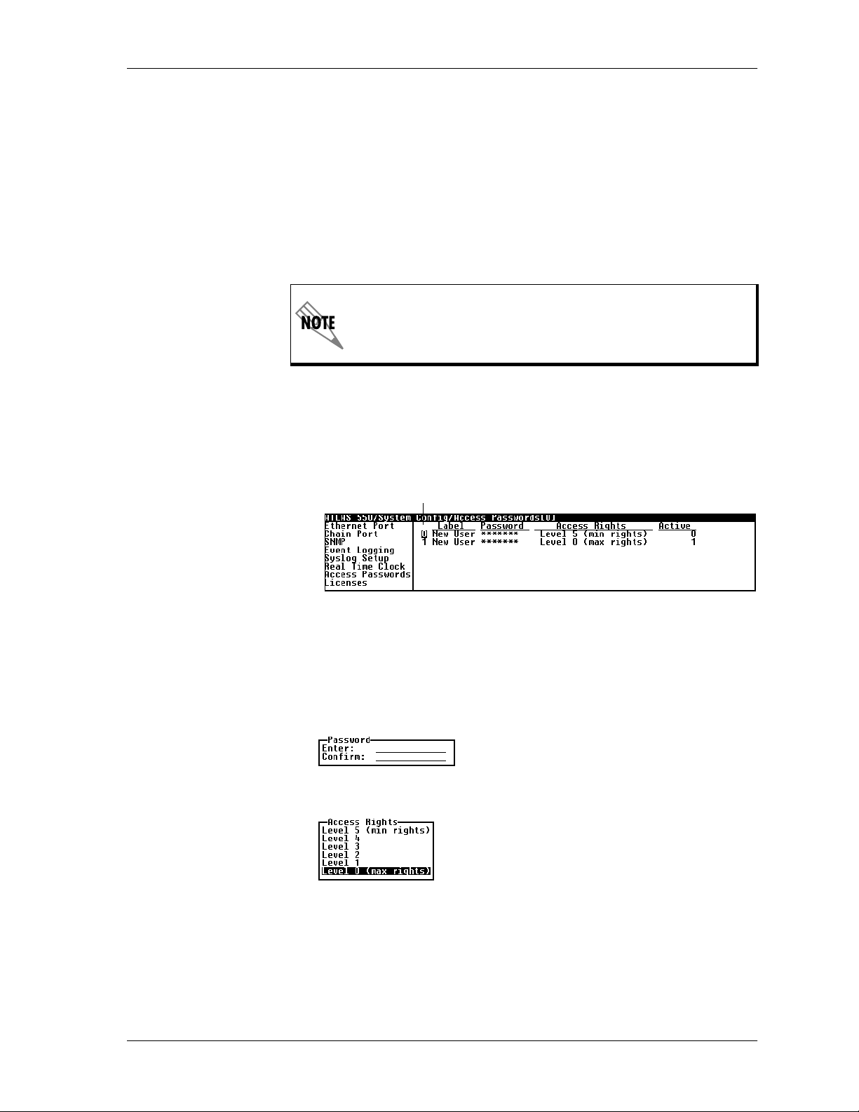
Chapter 6. System Control Terminal Menus
ACCESS
PASSWORDS
Instructions for Adding/Deleting Passwords
Write security: 0; Read security: 5
Provides a way to edit passwords and, also, to add new users and passwords. All menu items are protected by passwords of varying security levels. By assigning different passwords to different security levels, the
ATLAS 550 system administrator can control which users can change various menu items.
You can assign multiple passwords at the same access level. This way, different users with the same access privileges can have different passwords.
Table 6-1 on page 6-2 describes each of the six password security levels.
Passwords are case-sensitive.
Figure 6-4 shows the menu for addingand deleting passwords. The instructions follow.
Index Numbers
Figure 6-4. Menu for Adding/Deleting Passwords
Adding New Passwords
1. To add a new password,position the cursor over the index number 0
and press I.
2. Enter and confirm the new password.
3. Assign access rights (see also Table 6-1 on page 6-2).
Deleting Passwords
To delete a password, positionthe cursor over the index number of the password to be deleted and press D.
61200305L1-1 ATLAS 550 User Manual 6-15
Page 78

Chapter 6. System Control TerminalMenus
If you lose or forget theATLAS 550 system administrator password,
contact ADTRAN technical support (see last page of this manual)
for help in resetting the password.
ABEL
L
ASSWORD
P
CCESSRIGHTS
A
CTIVE
A
Write security: 0; Read security: 5
Defines a user name.
Write security: 0; Read security: 5
Allows you to change the password (the default password is
password
).
The current password displays as a series of asterisks (********). The password can contain up to 12 alphanumeric characters. Youcan also use spaces
and special characters in the password. Remember, passwords are case-sensitive.
Instructions for Changing Passwords
1. Select the P
2. Type the new password in the E
3. Type the new password again in the C
ASSWORD
field—a new P
NTER
ASSWORD
field.
ONFIRM
field displays.
field.
Write security: 0; Read security: 5
Defines the password level for the corresponding label. You can select from
six different password levels (see also Table 6-1 on page 6-2).
Write security: 0; Read security: 5
Displays the number of users for each label that are currently logged into
the system.
LICENSES
Write security: 0; Read security: 0
Provides menus to enable the optional ATLAS 550 feature upgrades.
EATURE
F
ICENSEKEY
L
ERIALNUMBER
S
IC CNT
L
Names the ATLAS 550 feature upgrade.
Displays the license key of the feature upgrade.
Displays the serial number of the feature upgrade.
Displays the number of instances of the feature that the license provides.
This field may not be applicable for a given feature—if it is not, this field is
blank.
6-16 ATLAS 550 UserManual 61200305L1-1
Page 79

Chapter 6. System Control Terminal Menus
TATUS
S
ALARM RELAY
RESET
ALARM RELAY
THRESHOLD
S
YSTEMUTILITY
Reflects the status, Permanent or Temporary, of the feature upgrade license
key.
Write security: 3; Read security: 5
Clears the Alarm Relay located on the rear panel of the ATLAS 550.
Write security: 3; Read security: 5
Defines which threshold sets the Alarm Relay. If an alarm occurs that is
greater than or equal to the threshold selected, the Alarm Relay will set.
These thresholds include, in descending order of importance, C
AJOR
M
set for M
Alarm Relay. However, setting the threshold to N
, M
INOR
AJOR
, W
ARNING
,andN
ORMAL
.Asanexample,ifthethresholdis
, then ALL Major alarms and ALL critical alarms will set the
ORMAL
RITICAL
will not set the
,
Alarm Relay for Normal events. No Normal events set the Alarm Relay.
Use the S
YSTEMUTILITY
menu to view andset the systemparametersshown
in Figure 6-5 .
Figure 6-5. System Utility Menu
UPDATE FIRMWARE
Write security: 1; Read security: 5
Updates firmware when ATLAS 550 enhancements are released. Two transfer methods are available for use in updating any modules that contain
Flash memory—including the ATLAS 550 system controller.
The first transfer method uses the ATLA S550 serial Control/Chain In port
of the system controller and XMODEM protocol. For detailed information
onhowtoupdatefirmwareusingthismethod,seeXMODEM Firmware Up-
dates on page 12-1.
The second transfer method uses the ATLAS 550 built-in Ethernet port of the
system controller and TFTP (Trivial File Transfer Protocol). For detailed information onhowtoupdatefirmwareusingthis method, see TFTP Firmware
Updates on page 12-3.
61200305L1-1 ATLAS 550 User Manual 6-17
Page 80

Chapter 6. System Control TerminalMenus
The available update options vary depending on whether you
select S
A
LOT
LLMODULES OF ATYPE
0, S
LOTS
1 through 4, R
ESOURCE
1through 4 or
.
ODULESLOT
M
ODULETYPE
M
RANSFER
T
ETHOD
M
Write security: 1; Read security: 5
Displays the slot youselect for firmware updating.
When this option first appears,
None Selected
displays. When you move the cursor to this field and
press
select S
through 4 or A
LLMODULES OF ATYPE
A
, a dialog box opens, allowing you to
Enter
LOT
0 through S
LLMODULES OF ATYPE
LOT
4, R
ESOURCE
is useful if several identical modules are installed
1
.
in the ATLAS 550.
Write security: 1; Read security: 5
ReflectsthemoduletypeselectedinM
only field; however, if you selected A
ODULESLOT
LLMODULES OF ATYPE
.Thisisnormallyaread-
,youmust
select a particular module type to update all modules of that type. The
selections only include upgradable modules.
Write security: 1; Read security: 5
Lists the two transfer methods for updating firmware:XMODEM and TFTP,
after selecting a module slot. XMODEM transfers files by connecting to a
communications program that supports XMODEM uploads to the terminal
interface. TFTP transfers files by specifying an appropriate server address
and filename:
TFTP S
ERVER
IP A
DDRESS
Write security: 1; Read security: 5
ConfigurestheIPaddressoftheTFTPServeronwhichtheupdatefile
resides. ATLAS 550 uses this field to locate the network server on which the
update file resides.
TFTP S
ERVERFILENAME
Write security: 1; Read security: 5
Identifies the name ofthe update file toretrievefromthe TFTPServer. Enter
the full path name and filename for the file.
ESTART
R
CHEDULE
S
Write security: 1; Read security: 5
Indicates when to restart the updated module to invoke the new code, after
selecting a module slot. The two options include R
FTERUPDATE
A
ESTARTIMMEDIATELYAFTERUPDATE
R
ESTART ATSPECIFIEDDATE ANDTIME
and R
ESTARTIMMEDIATELY
.
Automatically restarts the module immediately after the update is complete.
6-18 ATLAS 550 UserManual 61200305L1-1
Page 81

Chapter 6. System Control Terminal Menus
ESTART ATSPECIFIEDDATE ANDTIME
R
Lets you specify a date and time to automatically restart the updated module. (When you select this option, a new field called R
IME
displays below the current field.)
T
ESTARTDATE ANDTIME
R
ESTARTDATE AND
Write security: 1; Read security: 5
Defines the date and time to restart the system. Enter the time using a 24-hour format
(i.e., 23:25:30 fo r 11
PM
, 25 minutes, 30 seconds). Enter t he date in mm-
dd-yyyy format (i.e., 11-08-1999).
ESTART ATSPECIFIEDDATE ANDTIME
R
is only available for the
System Controller— not for modules residing in expansion slots,
since they are unable to maintain normal operation during the
update process.
URRENT
C
PDATESTATUS
U
Read security: 5
Indicates progress or problems encountered during the current update process. The field displays I
DLE
if no update is in progress or when the update
is successfully completed. At the end of asuccessful update, the contents of
this field are copied into P
Ifyouareupdatingseveralmodulesatthesametime(ifM
to ALL
ODULES OF ATYPE
M
REVIOUSUPDATESTATUS
), this option displays
[+]
.
ODULESLOT
is set
, indicatingthisfield con-
tains submenu items. The following submenus display:
LT
S
YPE
T
URRENT
C
TATUS
S
REVIOUS
P
TATUS
S
REVIOUSTIME
P
Indicates the slot number.
Defines the type of module for each slot.
Indicates t he status of the current update.
Indicates the status of the previous update.
Indicates t he time of the previous update.
During the TFTP upload process, various status messages are provided in
URRENTUPDATESTATUS
C
(see Table 12-1 on page 12-5).
REVIOUS
P
PDATESTATUS
U
Read security: 5
Displays the status of the previous update,after selecting a module slot. If a
firmware update has not been attempted for a particular slot, this field
reads
Has not been attempted.
Module Update Complete.
Following a successful update, the field reads
If an update was unsuccessful, the appropriate
error message displays.
61200305L1-1 ATLAS 550 User Manual 6-19
Page 82

Chapter 6. System Control TerminalMenus
EGIN
B
IRMWARE
F
PDATE
U
UPDATE STATUS
CONFIG TRANSFER
Write security: 1; Read security: 5
Begins updating the firmware for the selected modules. To start this action,
enter
to begin or enterNto cancel. You can also cancel the operation after
Y
the update has begun. For XMODEM updates, cancel theprocess via the
terminal emulation software (consult your documentation for information
on how to do this). For TFTP updates, you can cancel the process by selecting C
ANCELUPDATE
from this field.
Read security: 5
Displays the status of the current firmware update. These fields are identical to those defined earlier in Current Update Status.
Write security: 3; Read security: 5
Used only with TFTP transfers. Sends a file containing the ATLAS 550 configuration to a file on a TFTP Server using the TFTP protocol through the
Ethernet port. C
ONFIGTRANSFER
also lets you save the ATLAS 550 configu-
ration as a backup file, so you can use the same configuration with multiple
ATLAS 550 units. In addition, C
ONFIGTRANSFER
can retrieve a configura-
tion file from a TFTP Server.
To support these transfers, ADTRAN delivers a TFTP program with
ATLAS 550 called TFTP Server. You can configure any PC running Microsoft
Windows with this software, and store a configuration file. See TFTP Server
Utility on page 14-10 for details on how to use TFTP Server.
T
RANSFER
ETHOD
M
TFTP S
DDRESS
IP A
TFTP S
ILENAME
F
ERVER
ERVER
Before using C
ONFIGTRANSFER
, the ATLAS 550 should have a
valid IP address, subnet mask, and default gateway (if required),
and should be connected to an Ethernet network.
Only one configuration transfer session (upload or download) can be active
at a time. TheTCP/IP parameters are not savedor overwritten as part ofan
ATLAS 550 unit’s transferred configuration; this way, identical configurations can be sent to multiple units.
Write security: 3; Read security: 5
Displays the method used to transfer the configuration file to or from a
server.Currently,youmustuseTFTP.
Write security: 3; Read security: 5
Specifies the IP address of the TFTP Server. Get this number from your system administrator.
Write security: 3; Read security: 5
Defines the name of the configuration file that you transfer to or retrieve
fromtheTFTPServer.Thedefaultnameis
Atlas550.cfg
,butyoucanedit
this name.
6-20 ATLAS 550 UserManual 61200305L1-1
Page 83

Chapter 6. System Control Terminal Menus
URRENT
C
RANSFER
T
TATUS
S
REVIOUS
P
RANSFER
T
TATUS
S
OAD ANDUSE
L
ONFIG
C
AVECONFIG
S
EMOTELY
R
Read security: 5
Indicates the current status of the update.
Read security: 5
Indicates the status of the previousupdate.
Write security: 3; Read security: 5
Retrieves the configuration file specified in the
from the server. To start this command, enter
If you execute L
OAD ANDUSECONFIG
Y
the configuration file, reboots, then restarts using the new
configuration.
Write security: 3; Read security: 5
Saves the configuration file specified in TFTP S
server identified in TFTP S
to begin or enterNto cancel.
Y
ERVER
IP A
DDRESS
. To start this command, enter
TFTP Server Filename
field
to begin or enterNto cancel.
, the ATLAS 550 retrieves
ERVERFILENAME
to the
SYSTEM UTILIZATION
SYSTEM SELFTEST
Before using this command, you must have identified a valid TFTP
Server in TFTP S
ERVER
IP A
DDRESS
.
Write security: 0; Read security: 0
Displays statistics related to the ATLAS 550 internal operating system.
Please check with ADTRAN Technical Support before attempting to use
this menu.
Write security: 3; Read security: 5
Initiates a system self-test. The self-test consists of memory tests and data
integrity tests for each installed module.
Self-tests disrupt data flow.
61200305L1-1 ATLAS 550 User Manual 6-21
Page 84

Chapter 6. System Control TerminalMenus
ELFTEST
S
ELECTED
S
ESTS
T
URRENTTEST
C
TATUS
S
URRENTSLOT
C
ORT
P
IEWSELFTEST
V
OG
L
Write security: 3; Read security: 5
Runs system-wide Self-test, Memory, Flash, Bootrom, and PortTests. These
tests are disruptive to all data traffic; therefore, do not run these tests on a
unit unless data interruptions are acceptable. To confirm self-test activation,
press
; to cancel the self-test, pressN.
Y
Write security: 3; Read security: 5
Allows the user to select a system-wide test or an individual card test.
Choose from ALL TESTS, S
LOT:SLT0SYSCTRL
,oranyotherinstalled
option/network module.
Read security: 5
Displays which partof S
ELFTEST
is currently being run. See View Selftest Log
on page 6-22 for details on individual tests.
Read security: 5
/
Displays slot and port of the subsystem currently being tested.
Read security: 5
Displays time-stamped log of the tests conducted and the Pass/Fail results.
Self-tests verify data integrity and processor control to each port. Each port
is looped back and a data pattern is sent and tested. Theresult of the selftest on each installed port is listed with Pass/Fail results. Figure 6-6 shows
a typical test log.
Figure 6-6. View Self-test Log
The self-test log includes the following fields.:
I
DX
IME
T
L
S
T
P
VENT
E
ESULT
R
6-22 ATLAS 550 UserManual 61200305L1-1
Index number of the log.
Time and date of the log entry.
ATLAS 550 slot number.
ATLAS 550 port number.
Event description.
Shows Pass/Fail results.
Page 85

Chapter 6. System Control Terminal Menus
Table 6-2 lists the tests associated with the system controller.
Table 6-2. System Controller Tests
This event... Logs this result...
F
LASH
Verifies flash memory checksum.
PING
LEARSELF
C
TESTLOG
OOTROM
B
Verifies boot ROM checksum.
DSP RAM Verifies memory associated with the DSP.
RTC RAM Verifies memory associated with the real time clock.
TDM RAM
Verifies memory associated with mapping TDM bandwidth.
DRAM Verifies dynamic RAM used for program execution.
HDLC Verifies each HDLC controller used for frame relay or PRI.
Write security: 3; Read security: 5
-
Clears the self-test log.
Write security: 5; Read security: 5
Allows you to send pings (Internet Control Message Protocol (ICMP)
requests) to devices accessible via the network.
Only one ping session can be active at a time.
IP A
OUNT
C
IZE
S
IMEOUT
T
DDRESS
Write security: 5; Read security: 5
Specifies the IP address to ping.
Write security: 5; Read security: 5
Specifies the number of pings to send. The default number of tries is 4,and
the maximum value is 99.
Write security: 5; Read security: 5
Specifies the size in bytes of the data portion of the ping request. The
default value is 64 bytes, and the maximum size is 1024 bytes.
Write security: 5; Read security: 5
Specifies the time in milliseconds to wait for the ping reply before timing
out. The default timeout value is three seconds, and the maximum timeout
value is ten seconds.
61200305L1-1 ATLAS 550 User Manual 6-23
Page 86

Chapter 6. System Control TerminalMenus
OUND TRIP MIN
R
OUND TRIP AVG
R
OUND TRIP MAX
R
XSTATS
T
ESETSTATS
R
Read security: 5
Displays the minimum round trip time of the ping request/reply of the current set of pings.
Read security: 5
Displays the average round trip time of the ping request/reply of the current set of pings.
Read security: 5
Displays the maximum round trip time of the ping request/reply of the current set of pings.
Read security: 5
Displays the number of ping requests transmitted (
ping replies received (
n
LOST
).
lost (
n
RXED
) and the number of ping requests that were
TXED
), the number of
n
Write security: 5; Read security: 5
Resets all ping statistics to zero. If the ping client is active, this menu will
stop it.
TART/STOP
S
REBOOT SYSTEM
FACTORY DEFAULT
SYSTEM
Write security: 5; Read security: 5
If the ping client is currently idle, this menu sends pings to the specified
address. If the ping client is active, the menu stops sending pings.
Write security: 0; Read security: 0
Reboots the ATLAS 550. When you select this command, the following message displays: **WARNING ** This will reboot the entire system! Press
reboot the system, or
to exit the command.
N
to
Y
Write security: 0; Read security: 0
Resets the entire system to the factory default settings.To reset the system,
press
; to cancelthis command, pressN.
Y
6-24 ATLAS 550 UserManual 61200305L1-1
Page 87

Chapter 7
OVERVIEW
Module Terminal Menus
The controller board (slot 0) has two network interface slots. This chapter
only describes the module options available for the T1/PRI network
interface module. Individual option module menus are described in the
applicable module manuals.
The ATLAS 550 system controller automatically detects the presence of
modules when they are installed in the system. To view the menus for the
installed modules via the terminal menu, use the arrow keys to scroll to the
appropriate M
options in avertical mode, move thecursor to a slot number and press
on the keyboard.
ODULES
menu and press
. If you prefer to view these
Enter
Enter
M
ODULES
ODULES
The M
menu options that allow you to configure and control the installed option
modules, as well as the network ports.
main menu (see Figure 7-1) provides status information and
Figure 7-1. Modules Menu
61200305L1-1 ATLAS 550 User Manual 7-1
Page 88

Chapter 7. Module Terminal Menus
SLT
TYPE
Read security: 5
Identifies the slot number. Slot 0 refersto the ATLAS 550 Base Unit.
The ATLAS 550 has three types of slots: network slots, option module slots,
and resource module slots. The two network slots aredesignated N
TW
2. The four option moduleslotsaredesignated SLT1 through 4,andthe
N
four resource module slots are designated R
SC
1 through 4.
TW
1 and
Resource modules are installed onto any option module, but not onto network modules.
Write security: 3; Read security: 5
Displays the type of module actually installed in the slot or the type of
module you plan to install in the slot. TheATLAS 550 automatically detects
thetypeofmoduleinstalledineachslot,andtheT
YPE
field automatically
defaults to the installed module type. You can also use this field to preconfigure a unit before actually installing modules by specifying the module
that you want to install in each slot.
To use this option, navigate to the fieldyouwant to edit and press
Enter
.For
empty slots, a list of all the available module types displays. Select the one
you want and it displays in the T
with a module, you can only set this field to E
YPE
field. If this field is already configured
MPTY
.
MENU
ALARM
TEST
YPE
T
automatically displays the name of an installed module. If
you want to preconfigure the slot for a different type of module,
you must set this field to E
MPTY
before selecting another module
type.
Displays additional status and configuration menus for the ATLAS 550 or
selected module. To access the submenus for this item, use the arrow keys to
scroll to the M
ENU
column for the module you want to edit, and press
Enter
For detailed information on each submenu item, seeModules Menu
(T1Network Interface Module) on page 7-3.
Read security: 5
Displays an alarm conditionon the ATLAS 550 or selected module. To
access this menu, use the arrow keys and move to the A
then press
Enter
.
LARM
menu and
Read security: 5
Displays the type of test the ATLAS 550 or selected module is executing. To
initiate a test, select the M
ENU/TEST
option and then press
Enter
.Younow
have access to the screen that allows you to set up and initiate tests. See Tes t
on page 7-7 for details.
.
STATE
Read security: 5
Displays whether the ATLAS 550 or selected module is online or offline.
Even though a module is physically installed, it must be markedO
NLINE
for
it to be considered an available resource. This field allows an installed mod-
7-2 ATLAS 550 User Manual 61200305L1-1
Page 89

Chapter 7. Module Terminal Menus
STATUS
ule to be marked O
If you choose O
display O
FFLINE
FFLINE
, which may be useful in systemtroubleshooting.
FFLINE
, the module will not be in alarm condition, but will
.
Once a moduleisinstalled, S
TATE
must be set to O
NLINE
ATLAS 550 touse the module forany data bandwidth.O
for the
NLINE
is the default setting.
Read security: 5
Displays status information on the ATLAS 550 ports and other installed
modulesasfollows:
NLINE
O
The module is enabled and is responding to the system
controller’s status polls. Thisisthenormalresponseofthe
system.
ORESPONSE
N
Themoduleisenabledbutisnotrespondingtothe
system controller’s status polls. This response indicates a
problem in the system or that the module is not installed.
MPTY
E
The system controller has not detected the presence of a
module in the system, nor has a module been manually
enabled for this option slot.
FFLINE
O
The module is installed but has been taken offline by a
user. The module is still responding to controller polls.
REV
FFLINE/NO
O
ESPONSE
R
OT
N
UPPORTED
S
Read security: 5
The module is installed but has been taken offline by a
user. The module is not responding to polls.
Themoduleisnotsupportedbythecurrentsystem
configuration.
Displays the hardware revision of the ATLAS 550 and other installed modules.
Modules Menu (T1Network Interface Module)
This section provides detailed information on the M
menus. M
tus of various options, change theconfigurationforgeneral parameters, and
initiate tests. This section only describes the menu options for the T1 Network Interface Module. For detailsonmenu options for other modules, refer
totheappropriatemodulemanuals.
To configure the T1 Network Interface Module in the Dial Plan, use the descriptions provided for the Dual T1/PRI Module (see page 11-10).
ENU
provides access to commands that allow you to review the sta-
ODULES/MENU
sub-
61200305L1-1 ATLAS 550 User Manual 7-3
Page 90

Chapter 7. Module Terminal Menus
NFO
I
LARMSTATUS
A
Read security: 5
Displays general information about the T1/PRI network interface module
as follows:
ARTNUMBER
P
ERIALNUMBER
S
SSEMBLY
A
EVISION
R
Displays the part number of the T1/PRI network interface.
Displays the module’s serial number.
Displays the assembly revision.
Read security: 5
Displays any active alarms as follows:
RT
P
Displays the port number. The T1/PRI Network Interface
Module is a single-port device.
LARMS
A
Displays the al arm type. Table 7-1 describeseach alarm type.
Table 7-1. Alarm Types
LOS (Loss of Signal) No signal detected on port interface.
DS0 S
TATUS
RED (Red Alarm) Not able to frame data received on the port.
Alternately referred to as Out of Frame (OOF).
YELLOW (Yellow Alarm) Remote alarm indicator (RAI) being re-
ceived on port.
B
LUE
(Blue Alarm) Receiving unframed all ones from the port
alarm indicator signal (AIS).
DS0 A
XLEVEL
R
LARM
At least one DS0 channel is in alarm.
(Receive Level) Indicates the strength of the signal re-
ceived on the port.
Read security: 5
Indicates usage on a DS0 basis for each port as follows.
* Inactive
A Active call on this DS0
D Active D channel DS0
M Maintenance DS0
N Dedicated DS0
O Off-hook detected
R Ringing detected
7-4 ATLAS 550 User Manual 61200305L1-1
Page 91

Chapter 7. Module Terminal Menus
LARMS
DS0 A
IGSTATUS
S
ERFORMANCE
P
URR
C
Read security: 5
Indicates DS0 alarm as follows:
- No alarm DS0
D D channel alarm (ISDN)
F Frame alarm (packet)
T TBOP alarm (packet)
Read security: 5
Displays the A/B signaling bits for Rx and Tx DS0s.
Write security: 3; Read security: 5
:
Theperformancefields–eithercurrent,15minutetotal,or24hourtotal–
provide status on key performance measures as specified in ANSI T1.403
and AT&T TR54016 for the T1/PRI port as follows:
RT
P
LR
C
Displays the port number.
Clears information for the selected port. Press
Enter
when the
cursor is over this field to clear the data.
ES An ES is a second with one or more error events or one or more
Out Of Frame events or one or more Controlled Slips.
ERFORMANCE
P
IN
15 M
BES Bursty Errored Seconds. A BES is a second with more than one,
but less than 320 error events.
SES Severely Errored Seconds. An SES is a second with 320 or more
error events or one or more Out Of Frame events.
SEFS Severely Errored Frame Seconds.
LOFC Loss of Frame Count.
CSS Controlled Slip Seconds.
UAS Unavailable Seconds.
LCV Line Code Violations.
PCV Path Code Violations.
LES Line Errored Seconds.
Write security: 3; Read security: 5
:
In the P
ERFORMANCE15MIN
menu, the performance data for the previous
15 minute window is stored. Refer to Performance: Curr on page 7-5 for a
detailed description.
ERFORMANCE
P
R
24 H
Write security: 3; Read security: 5
:
Stores the performance data for the previous 24-hour window. Refer to Performance: Curr on page 7-5 for a detailed description.
61200305L1-1 ATLAS 550 User Manual 7-5
Page 92

Chapter 7. Module Terminal Menus
ONFIGURATION
C
All of these configurable parameters depend on whether theport is connected to a Primary RateISDN circuit or a Channelized T1 circuit—dedicated or
switched.
RT
P
Read security: 5
Identifies the port number.
ORTNAME
P
Write security: 3; Read security: 5
Accepts any alphanumeric name up to 16 characters long to uniquely identify each port.
RAME
F
Write security: 2; Read security: 5
Matches the frame format of the circuit to whichit is connected(available
from the network supplier).
ODE
C
Write security: 2; Read security: 5
Matches the line code of the circuit to which itis connected (available from
the network supplier).
XYELLOW
T
Write security: 3; Read security: 5
Enables and disables yellow alarm transmissions.
X
T
PRM
S
Write security: 3; Read security: 5
Enables and disables PRM data transmissions on the facility data link
(FDL). The PRM data continues to be collected even if T
X
PRM
S
is disabled
(possible only with ESF format).
LBO
Write security: 2; Read security: 5
Depends on whether the circuit is provisioned for DS1 by the telephone
company.
CCEPT
LB A
Write security: 3; Read security: 5
Sets unit to accept orreject the in-band loop up and loop down codes as
defined in ANSI T1.403. This is a line loopback.
ULSEDENSITY
P
Write security: 3; Read security: 5
When O
N
, the ATLAS 550 monitors for o nes (1s) density violations and
inserts a one (1) when needed to maintain ones at 12.5%.
7-6 ATLAS 550 User Manual 61200305L1-1
Page 93

Chapter 7. Module Terminal Menus
T
EST
Initiates different types of tests and displays test results.
These T
RT
P
EST
commands temporarily disrupt service.
Identifies the port number.
OC
LB
L
Write security: 4; Read security: 5
Causes loopback on near-end port. (Local Loopback)
INE
L
AYLD
P
EMOTE
R
Metallic loopback.
Payload loopback framing and clocking are regenerated.
LB
Write security: 4; Read security: 5
Sends a loopback code to a remote CSU.
ANSI FDL L
ANSI FDL P
INE
YLD
Sends ANSI line loopback code. Requires ESF mode.
Sends ANSI payloadloopback code. Requires ESF
mode.
ATT I
ATTERN
P
NBANDLINE
Sends line loopback using inband code.
Write security: 4; Read security: 5
Specifies the test pattern to be transmitted out the port.
LL ONES
A
LL ZEROS
A
Framed ones
Framed zeros
QRSS Pseudorandom pattern with suppression of excess zeros
QRSS/RLB R
ESULTS
Read security: 5
(Remote Test Pattern Results) Suppresses excess zeros—indication of sync
and errors of received data pattern.
LR
C
Write security: 3; Read security: 5
(Test Pattern Results Clear) Clears current error counters on test pattern
results menu.
NJ
I
Write security: 3; Read security: 5
(Test Pattern Error Inject) Injects errors into transmitted test pattern.
61200305L1-1 ATLAS 550 User Manual 7-7
Page 94

Chapter 7. Module Terminal Menus
7-8 ATLAS 550 User Manual 61200305L1-1
Page 95

Chapter 8
Packet Manager
OVERVIEW
ACKETMANAGER
The P
points. A packet endpoint is a virtual port within the ATLAS 550 into which
aspecifiedphysical port (a T1 or an Nx56/64) terminates its data for further
routing by the system. All packet services, including the ATLAS 550 frame
relay, must have defined packet endpoints.
Your frame relay provider furnishes specific information on defining the
packet endpoint. This information includes signaling type (Annex A,
Annex D, or LMI) and definitions for all active PVCs. The P
submenu map connects protocols from packet endpoint to packet endpoint.
In addition to defining packet endpoints, you must also configure the physical port before it can run frame relay (see also Chapter 10, Dedicated Maps
and Chapter 11, Dial Plan).
PACKET MANAGER MENUS
menu contains submenus that define packet end-
ACKETCNCTS
ACKETMANAGER
The P
layer 2 connections, including frame relay endpoints. These submenus, discussed in this chapter, include P
S
ORT
,andF
RAMERELAY
menus(seeFigure8-1)defineandconfigureall
ACKETENDPNTS
IQ. Seealso,themenutreeinFigure8-2onpage8-2.
Figure 8-1. Packet Manager Menu
ACKETCNCTS
, P
, C
NCTS
61200305L1-1 ATLAS 550 User Manual 8-1
Page 96

Chapter 8. Packet Manager
Status Sig Role Link Stats Name State Changes
Performance Rx Pckts Full Status Rx
Packet
Endpnts
Config User Bad Event Threshold (N392)
Endpnt Name Endpnt Name Tx Pckts
Prot Protocol Rx Pckts
Sig Type DLCI Signaling Errors
Sig State Sublink Stats State Signaling Timeout
Current Port Tx Pckts Full Status Tx
Statistics Link Integrity Status Tx
Signaling Role Link Integrity Status Rx
Signaling Type Clear Counters
Endpnt Name User Poll Timer (T391)
Protocol User Polls Per Status (N391)
Config User Event Window Size(N393)
Net Poll Timer (T391)
Net Poll Response Timeout (T392)
Net Polls PerStatus (N391)
Net Bad Events Threshold (N392)
Net Event Window Size(N393)
Sublinks DLCI In-band Sequence Number
Test Burst React to BECN
Endpnt Count
Endpnts Sort
PacketCncts Sublink Duration Avg Rx Thru
To Pkt Endpt/Sublink Avg Tx Thru Avg Rx Thru
Cncts Sort From Pkt Endpt/Sublink Max Tx Util% Max Rx Util%
Connection Protocol Avg Tx Util% Avg Rx Util%
Off Port UA Time Tx Frames
Enable IQ Stats Signal Error Max Tx Thru
Port Enables
Frame Relay IQ
Config Max Days Async Status Rx BECN
View IQ Statistics Interval/Day Aborts Rx DE
Usage QOS Remote FECN Notification
Endpt Name Config Drop DE Packets when overloaded
Protocol Fragmentation Threshold
Sublink Name Rx Frames Fragmentation Size
From: PEP Test Max Rx Thru Diagnostic Mode
To: PEP Results Max Rx Util%
Sublink Avg Rx Util%
Protocol Tx Frames Rx Frames
Config Tx Bytes Rx Bytes
Name Sig State Chg Max Tx Util%
Enable Rx Full Stat Avg Tx Util%
All Sublinks Tx Full Stat PVC IA Time
Sublinks Current PIV Rx LI only Rx FECN
Sublink Min Tx Frame
Name
DLCI Rx Bytes DLCI State
Max Tx Thru Max Rx Thru
SigDownTime TxBytes
Signal T/O Avg Tx Thru
Interval Period Tx LI only Tx FECN
Max Intervals Discard Frame Tx BECN
CRC Error Tx DE
Octet Align Rx CR
Length Error Tx CR
EA Violation Lost Frames
Inactive DLCI Rmt Lost Frms
Invalid DLCI Rx Burst Sec
Tx Burst Sec
Min Rx Frame
Max Rx Frame
Avg Rx Frame
MaxTxFrame
Avg Tx Frame
Min Frame Dly
Max Frame Dly
Avg Frame Dly
PVC State Change
Figure 8-2. Packet Manager Menu Tree
8-2 ATLAS 550 User Manual 61200305L1-1
Page 97

Chapter 8. Packet Manager
P
ACKETENDPNTS
STATUS
NDPNTNAME
E
ROT
P
S
IGROLE
ACKETENDPNTS
The P
Submenus include S
NDPNTSSORT
and E
TATUS
S
submenus display the status of each packet endpoint including the
packet endpoint name (E
ing role (S
TATE
S
IGROLE
), and the connections (C
menu defines, monitors, and tests a packet endpoint.
TATUS
ERFORMANCE
, P
, C
ONFIG
, T
EST
, E
NDPNTCOUNT
.
NDPNTNAME
), the protocol type (P
), the signaling type (S
URRENTPORT
IGTYPE
), the signaling state (S
). The following sections dis-
ROT
), the signal-
,
IG
cuss each of these fields.
Read Security: 5
Displays the packet endpoint name as defined in the P
ONFIGMENU
C
(also see Config on page 8-6).
ACKETENDPNTS
/
Read Security: 5
Displays the layer 2 protocol that this packet endpoint terminates. FRindicates that this packet endpoint is configured for frame relay. TBOP indicates that this packet endpoint is configured for Transparent Bit Oriented
Protocol (TBOP).
Read Security: 5
IGTYPE
S
Displays the frame relay signaling role for this packet endpoint. The
selections include O
FF
O
FF
NKNOWN
, U
ETWORK
, N
, U
SER
,andB
OTH
.
Indicates that the endpoint is configured so that it does not use signaling.
NKNOWN
U
Indicates that the endpoint is configured to auto-detect the role, but has not
yet done so.
ETWORK
N
Indicates that the endpoint is acting as the network end of a UNI link.
SER
U
Indicates that the endpoint is acting as one end of a UNI link.
OTH
B
Indicates that the endpoint is acting as one end of an NNI link.
Read Security: 5
Displays the frame relay signaling type used on this packet endpoint. Selections include U
NKNOWN
U
NKNOWN
, A
NNEX
A, A
NNEX
D,andLMI.
Indicates that the endpoint is configured to auto-detect the signaling standardtouse,buthasnotyetdoneso.
61200305L1-1 ATLAS 550 User Manual 8-3
Page 98

Chapter 8. Packet Manager
NNEX
A
A
TheendpointissignalingusingITU-TQ.933-A.
NNEX
A
D
TheendpointissignalingusingANSIT1.617-D.
LMI
The endpoint is signaling using Group of Four LMI specification.
IGSTATE
S
URRENTPORT
C
PERFORMANCE
NDPNTNAME
E
ROTOCOL
P
Read Security: 5
Indicates the current condition (i.e., active frame relay signaling) of this
packet endpoint, as defined by the frame relay configuration settings. This
field is either A
CTIVE
or I
NACTIVE
.
Read Security: 5
Displays the connections for the packet endpoint. The letter
indicates that this packet endpoint is used in the P
ACKETCNCTS
U
in this field
map (also
see Packet Cncts on page 8-13). The remainder of the field indicatesthe
physical port to which this packet endpoint is connected, as defined in the
D
EDICATEDMAP
(also see Dedicated Maps on page 10-1). If the port is a chan-
nelized interface such as a T1, the DS0 assignment is also provided.
Displays performance information for each packet endpoint including E
PNTNAME
(endpoint name), P
ROTOCOL
INKSTATS
, L
,andS
UBLINKSTATS
ND
.
Read Security: 5
Displays the packet endpoint name as defined in PACKET
NDPNTS/CONFIG
E
(also see Config on page 8-6).
Read Security: 5
Displays the layer 2 protocol that this packet endpoint terminates as
defined in P
ACKETENDPNTS/CONFIG
(also see Configon page 8-6).
-
INKSTATS
L
Read Security: 5
Displays layer 2 performance statistics. This field is dependent on the type
of protocol (Frame Relay or TBOP) selected in P
ACKETENDPNTS/CONFIG
(also see Config on page 8-6).
Frame Relay Statistics
These fields reflect the total count since last cleared:
XPACKETS
T
Total number of frame relay packets transmitted through th is packet endpoint, including both user data (on all PVCs) and signaling.
XPACKETS
R
Total number of frame relay packetsreceived through this packet e ndpoint
(on all PVCs).
8-4 ATLAS 550 User Manual 61200305L1-1
Page 99

Chapter 8. Packet Manager
TATECHANGES
S
Totalnumber of times thatframerelaysignalinghas gone activeorinactive.
IGNALINGERRORS
S
Total number of signaling frames received with PVC signaling protocol violations.
IGNALINGTIMEOUTS
S
Number of times signaling polls were not received in the time specified in
T391 in the P
ULLSTATUSTX
F
ACKETENDPNTS/CONFIG
menu (also see Config on page 8-6).
Number of full status polls transmitted by this packet endpoint.
ULLSTATUSRX
F
Number of full status polls received by this packet endpoint.
INKINTEGRITYSTATUSTX
L
Number of link integrity polls transmitted by this packet endpoint.
INKINTEGRITYSTATUSRX
L
Number of link integrity polls received by this packet endpoint.
UBLINKSTATS
S
LEARCOUNTERS
C
Clears all values in this submenu.
TBOP Statistics
These statistics reflect the total count since last cleared:
XPACKETS
T
Displays the total number of HDLC packets transmitted through this
packet endpoint.
XPACKETS
R
Displays the total number of HDLC packets received through this
packet endpoint.
LEARCOUNTERS
C
Clears all values in this submenu.
Read Security: 5
Displays frame relay performance statistics for supported packet endpoint
sublinks. These statistics fields reflect the total count since last cleared.
AME
N
User-defined name of a sublink (PVC).
DLCI
DLCI for sublink as defined in P
ACKETENDPNTS/CONFIG
(also see Config on
page 8-6).
TATE
S
Indicates if this particularsublink (PVC) has been definedas active by a full
status poll.
61200305L1-1 ATLAS 550 User Manual 8-5
Page 100

Chapter 8. Packet Manager
P
U
PVC is up (active).
OWN
D
PVC is down (inactive).
XPCKTS
T
Total number of frame relay user data packets transmitted over this PVC.
XPCKTS
R
Total number of frame relay user data packets received over this PVC.
TATISTICS
S
Providesadditional information, as follows, on the individual sublink:
CONFIG
NDPNTNAME
E
BECN C
OUNT
TotalnumberofBECNbitsreceivedonthisPVC.
ISCARDCOUNT
DE D
Total number of Discard Eligible bits that have been received on this
PVC.
FECN C
OUNT
Total number of FECN bits received on this PVC.
ESETCOUNTERS
R
Resets all sublink counters.
Creates and configures packet endpoints.
One HDLC resourceis used by each PRI or each PacketEndpoint.
Write Security: 3; Read Security: 5
Simplifies configuration with user-definable names such as the name of the
frame relay provider or the circuit ID.
ROTOCOL
P
Write Security: 3; Read Security: 5
Defines the protocol operating on this port. F
RAMERELAY
configures this
packet endpoint to frame relay. TBOP configures this packet endpoint as
transparent bit oriented protocol.
ONFIG
C
Write Security: 3; Read Security: 5
Displaysthe configuration for thispacketendpoint. This menu isprotocoldependent. TBOP requires no configuration.
IGNALINGROLE
S
Defines whether this packet endpoint acts as the network or user sideof the
UNI or as an NNI.
8-6 ATLAS 550 User Manual 61200305L1-1
 Loading...