

Page 1

ATLAS Frame Relay
User Manual
Part Number 1200263L1-1
61200263L1-1.1D
May 2000
Page 2

901 Explorer Boulevard
P.O. Box 140000
Huntsville, AL 35814-4000
(256) 963-8000
© 2000 ADTRAN, Inc.
All Rights Reserved.
Printed in U.S.A.
Page 3

Table of Contents
ListofFigures ..........................................................................vii
ListofTables...........................................................................xi
Chapter1 IntroducingATLASFrameRelay..............................................1-1
FrameRelayOverview.................................................................. 1-1
FrameRelayFeatures ................................................................... 1-2
Specifications ..........................................................................1-2
Chapter2 TechnologyOverview ....................................................... 2-1
OSIModel ............................................................................2-1
Example1: OSIModelRelatedtoProcessofMailingaLetter.................................2-2
Example2: OSIModelRelatedtoProcessofMovingDataPacket.............................2-3
FrameRelay ...........................................................................2-3
VirtualCircuits.....................................................................2-3
PVCPhysicalConnections........................................................ 2-4
DataLinkConnectionIdentifier(DLCI)................................................ 2-5
User-to-NetworkInterface ........................................................... 2-5
LocalManagementInterface(LMI) ................................................2-6
AnnexAandAnnexD...........................................................2-6
CommittedInformationRate(CIR).................................................... 2-6
ManagingNetworkCongestion....................................................... 2-7
TBOP................................................................................. 2-8
PPP ..................................................................................2-8
LinkControlProtocol................................................................2-8
NetworkControlProtocols...........................................................2-8
Chapter3 EnablingFrameRelay .......................................................3-1
InstallingtheTemporaryLicenseKey..................................................... 3-2
ObtainingthePermanentLicenseKey ....................................................3-2
InstallingthePermanentLicenseKey ..................................................... 3-3
61200263L1-1.1 ATLAS Frame Relay User Manual iii
Page 4

Table of Contents
Chapter 4 Defining Packet Endpoints. . . . . . . . . . . . . . . . . . . . . . . . . . . . . . . . . . . . . . . . . . . . . . . . . . . . 4-1
Overview..............................................................................4-1
Passwords .............................................................................4-1
NavigatingtheTerminalMenus ..........................................................4-1
ThePacketManagerMenu ...............................................................4-2
PacketEndpnts .........................................................................4-2
Status..............................................................................4-2
EndpntName ...................................................................4-2
Prot............................................................................4-3
SigRole.........................................................................4-3
SigType........................................................................4-3
Active(FrameRelay).............................................................4-3
Active(PPP).....................................................................4-3
CurrentPort.....................................................................4-4
Performance........................................................................4-5
EndpntName ...................................................................4-5
Protocol ........................................................................4-5
LinkStats(FrameRelay)..........................................................4-5
LinkStats(TBOP)................................................................4-6
LinkStats(PPP)..................................................................4-7
SublinkStats ....................................................................4-8
Config .............................................................................4-9
EndpntName ...................................................................4-9
Protocol ........................................................................4-9
Config..........................................................................4-9
ChoosingtheSignalingRoleforBackupLinks ..................................4-11
Sublinks.......................................................................4-15
SublinksExample...............................................................4-18
Usage .........................................................................4-19
Test...............................................................................4-19
EndpntName ..................................................................4-19
Protocol .......................................................................4-19
Sublink........................................................................4-20
EndpntCount......................................................................4-21
EndpntsSort.......................................................................4-21
PacketCncts ..........................................................................4-22
From:PEP.........................................................................4-22
Sublink............................................................................4-22
To:PEP............................................................................4-22
Sublink............................................................................4-22
Protocol...........................................................................4-23
Config ............................................................................4-23
Conflict........................................................................4-23
From..........................................................................4-23
To.............................................................................4-23
CnctsSort.............................................................................4-23
FrameRelayIQ........................................................................4-23
Chapter5 ConnectingPacketEndpoints.................................................5-1
DedicatedMaps ........................................................................5-1
DialPlan ..............................................................................5-1
iv ATLAS Frame Relay User Manual 61200263L1-1.1
Page 5

Table of Contents
PktEndpt .......................................................................... 5-2
Slot/Svc........................................................................5-2
Prt/PEP........................................................................5-2
Sig.............................................................................5-2
In#Accept ...................................................................... 5-2
Out#Rej........................................................................5-2
IfceConfig......................................................................5-2
PktVoice...........................................................................5-6
Slot/Svc........................................................................5-6
Prt/PEP........................................................................5-6
Sig.............................................................................5-6
In#Accept ...................................................................... 5-6
Out#Rej........................................................................5-6
IfceConfig......................................................................5-6
CallerID....................................................................... 5-7
SourceID....................................................................... 5-7
NetworkTerm...................................................................... 5-8
DIDDigitsTransferred...........................................................5-8
DIDPrefix...................................................................... 5-8
TrunkNumber.................................................................. 5-8
UserTerm .........................................................................5-8
DIDDigitsTransferred...........................................................5-8
CallerIDNumber............................................................... 5-8
SourceID....................................................................... 5-8
Chapter6 FrameRelayConfigurationExamples..........................................6-1
Example1: IPRoutingNetwork—ATLASastheCentral-SiteRouter..........................6-2
Example2: IPRoutingNetwork—ExternalRouters.........................................6-4
Example3: PrivateFrameRelayNetwork—ATLASCentral-SiteRouter.......................6-6
Example4: PublicFrameRelayNetwork—IPDataandPacketVoice..........................6-8
Example5: PrivateFrameRelayNetwork—PacketVoice...................................6-10
Example6: IPRoutingNetworkwithDialBackup.........................................6-13
Example7: PrivateframerelayNetworkwithDedicatedBackup............................6-17
Example8: IPRoutingUsingPPP.......................................................6-20
Chapter7 UsingFrameRelayIQ ....................................................... 7-1
FrameRelayIQ ........................................................................ 7-1
EnableIQStats .....................................................................7-1
PortEnables........................................................................7-1
Name..........................................................................7-1
EnablePort..................................................................... 7-2
AllSublinks .................................................................... 7-2
Sublinks........................................................................ 7-2
Config.............................................................................7-2
CurrentPIVs.................................................................... 7-2
IntervalPeriod.................................................................. 7-2
MaxDays ......................................................................7-2
MaxIntervals...................................................................7-2
ViewIQStatistics................................................................... 7-3
61200263L1-1.1 ATLAS Frame Relay User Manual v
Page 6

Table of Contents
Interval/Day(Link).............................................................7-3
Sublink.........................................................................7-5
AppendixA Troubleshooting..........................................................A-1
AppendixB Glossary ................................................................. B-1
Index..............................................................................Index-1
vi ATLAS Frame Relay User Manual 61200263L1-1.1
Page 7

List of Figures
Figure1-1. TypicalPoint-to-PointCircuit................................................1-1
Figure1-2. FrameRelayCircuit........................................................ 1-2
Figure2-1. ThreeVirtualCircuitsinOnePhysicalCircuit..................................2-4
Figure2-2. FrameRelayNetworkusingVirtualCircuits................................... 2-4
Figure2-3. NetworkUsingDLCIAssignments...........................................2-5
Figure2-4. NetworkCongestionandFlowControl....................................... 2-7
Figure4-1. PacketManagerMenu...................................................... 4-2
Figure4-2. StatusMenuTree .......................................................... 4-2
Figure4-3. PerformanceMenuTree .................................................... 4-5
Figure4-4. FrameRelayLinkStatsMenuTree ...........................................4-5
Figure4-5. TBOPLinkStatsMenuTree................................................. 4-6
Figure4-6. PPPLinkStatsMenuTree................................................... 4-7
Figure4-7. FrameRelaySublinkStatsMenuTree......................................... 4-8
Figure4-8. ConfigMenuTree.......................................................... 4-9
Figure4-9. Config/ConfigMenuTree(FrameRelay).....................................4-10
Figure4-10. Config/ConfigMenuTree(PPP)............................................ 4-13
Figure4-11. SublinksMenuTree....................................................... 4-15
Figure4-12. TestMenuTree...........................................................4-19
Figure4-13. EndpntCountMenuTree..................................................4-21
Figure4-14. EndpntsSortMenuTree................................................... 4-21
Figure4-15. PacketConnectsMenu.....................................................4-22
Figure4-16. CnctsSortMenu.......................................................... 4-23
Figure5-1. DedicatedMapsMenu...................................................... 5-1
Figure5-2. DialPlanMenu............................................................5-1
Figure5-3. Port/PEPOptionsintheDialPlan ...........................................5-2
Figure5-4. PacketLinkInterfaceConfiguration..........................................5-3
Figure5-5. PacketLinkInterfaceConfigurationwithFRBackupSupport.................... 5-3
Figure5-6. PacketLinkGROUPInterfaceConfiguration................................... 5-3
Figure5-7. CallRoutingTableforRoutingUsingIncomingNumber........................5-5
Figure5-8. CallRoutingTableforRoutingUsingCallPartyNumber .......................5-5
Figure5-9. CallRoutingTableforRoutingUsingDBUHandshake .........................5-5
Figure5-10. PacketSwitchedVoiceOptions ..............................................5-6
Figure5-11. InterfaceConfigurationPanel................................................5-6
Figure6-1. ATLAStoSupportPacketDataConfiguration................................. 6-1
61200263L1-1.1 ATLAS Frame Relay User Manual vii
Page 8

List of Figures
Figure6-2. IPRoutingNetworkwithATLASastheCentral-SiteRouter......................6-2
Figure6-3. MenuforCreatingPacketEndpoints..........................................6-2
Figure6-4. MenuforCreatingSublinksorDLCIs.........................................6-2
Figure6-5. MenuforConnectingIPTraffictoInternalRouter...............................6-3
Figure6-6. MenuforAttachingPacketEndpointtoPhysicalInterface .......................6-3
Figure6-7. IPNetworkWithExternalRouters............................................6-4
Figure6-8. MenuforCreatingthePacketEndpoints.......................................6-4
Figure6-9. MenuforConfiguringPacketEndpoints(1)Sublinks............................6-5
Figure6-10. MenuforConfiguringPacketEndpoints(2)Sublinks............................6-5
Figure6-11. MenuforMakingthePacketConnections......................................6-5
Figure6-12. MenuforConnectingPacketEndpointstoPhysicalPort.........................6-5
Figure6-13. PrivateFrameRelayNetwork—ATLASCentral-SiteRouter......................6-6
Figure6-14. MenuforCreatingPacketEndpoints..........................................6-6
Figure6-15. MenuforCreatingSublinks..................................................6-6
Figure6-16. MenuforConnectingPacketEndpoints........................................6-7
Figure6-17. MenuforConnectingPacketEndpointtoPhysicalInterface......................6-7
Figure6-18. PublicFrameRelayNetwork.................................................6-8
Figure6-19. MenuforCreatingPacketEndpoint...........................................6-8
Figure6-20. MenuforConfiguringSublinks...............................................6-9
Figure6-21. MenuforConnectingPacketData.............................................6-9
Figure6-22. MenuforConfiguringDialPlan..............................................6-9
Figure6-23. MenuforConnectingPacketEndpoints........................................6-9
Figure6-24. PrivateFrameRelayNetworkUsingCompressedVoice ........................6-10
Figure6-25. MenuforCreatingPacketEndpoints.........................................6-10
Figure6-26. MenuforConfiguringSublinks..............................................6-11
Figure6-27. MenuforConnectingtheTBOPEndpoints....................................6-11
Figure6-28. MenuforConnectingPacketEndpointstoPhysicalLinks.......................6-11
Figure6-29. ConnectingPBXDS0toFrameRelayEndpoint................................6-12
Figure6-30. ConnectingFREndpointtoFRPrivateNetwork...............................6-12
Figure6-31. IPRoutingNetworkwithDialBackup........................................6-13
Figure6-32. MenuforCreatingthePacketEndpoints......................................6-13
Figure6-33. MenuforConfiguringPacketEndpoint1(Server)Sublinks......................6-14
Figure 6-34. Menu for Configuring Packet Endpoint 2
(XYZNetwork)Sublinks....................................................6-14
Figure 6-35. Menu for Configuring Packet Endpoint 3
(ChicagoBackup)Sublink ..................................................6-14
Figure 6-36. Menu for Configuring Packet Endpoint 4
(NewYorkBackup)Sublink.................................................6-14
Figure 6-37. Menu for Configuring Packet Endpoint 5
(BostonBackup)Sublink....................................................6-14
Figure6-38. MenuforConfiguringBackupSublink1......................................6-15
Figure6-39. MenuforMakingthePacketConnections.....................................6-15
Figure6-40. MenuforConnectingPacketEndpointstoPhysicalPort........................6-15
Figure6-41. MenuforAddingBackupPacketEndpointstotheDialPlan.....................6-16
viii ATLAS Frame Relay User Manual 61200263L1-1.1
Page 9

List of Figures
Figure 6-42. Menu for Configuringthe Switched Packet Endpoint
InterfaceConfiguration.................................................... 6-16
Figure6-43. MenuforConfiguringthePRIConnectionstothePSTN........................6-16
Figure6-44. PrivateFrameRelayNetworkwithDedicatedBackup.........................6-17
Figure6-45. MenuforCreatingPacketEndpoints ........................................ 6-17
Figure6-46. MenuforConfiguringSublinks.............................................6-18
Figure6-47. MenuforConfiguringSublinks.............................................6-18
Figure6-48. MenuforConfiguringBackupVoiceSublink .................................6-18
Figure6-49. MenuforConfiguringBackupSignalingSublink.............................. 6-18
Figure6-50. MenuforMakingthePacketConnections.................................... 6-19
Figure6-51. MenuforConnectingPacketEndpointstoPhysicalPorts....................... 6-19
Figure6-52. MenuforConnectingPacketEndpointstoPhysicalPorts....................... 6-19
Figure6-53. PrivateFrameRelayNetworkwithDedicatedBackup.........................6-20
Figure6-54. MenuforCreatingPacketEndpoints ........................................ 6-20
Figure6-55. MenuforConfiguringSublinks.............................................6-20
Figure6-56. MenuforConfiguringSublinks.............................................6-21
Figure6-57. MenuforConfiguringBackupVoiceSublink .................................6-21
Figure6-58. MenuforMakingthePacketConnections.................................... 6-21
Figure6-59. MenuforConnectingPacketEndpointstoPhysicalPorts....................... 6-21
Figure7-1. FrameRelayIQMenus .....................................................7-1
Figure7-2. ViewIQStatisticsMenuTree................................................ 7-3
61200263L1-1.1 ATLAS Frame Relay User Manual ix
Page 10

List of Figures
x ATLAS Frame Relay User Manual 61200263L1-1.1
Page 11

List of Tables
Table1-1. FrameRelaySpecifications....................................................1-3
Table2-1. Seven-LayerOSIModel....................................................... 2-1
Table2-2. LMI(GroupofFour)DLCIAssignments........................................2-6
Table2-3. AnnexAandAnnexDDLCIAssignments...................................... 2-6
Table4-1. SuggestedFragmentationValuesBasedonthePVCCIR.........................4-16
61200263L1-1.1 ATLAS Frame Relay User Manual xi
Page 12

List of Tables
xii ATLAS Frame Relay User Manual 61200263L1-1.1
Page 13
Chapter 1
Introducing ATLAS Frame
Relay
FRAME RELAY OVERVIEW
Frame relay is a packet-switched service that allows efficient transfer of
bursty trafficinawidearea network (WAN) environment (see also Frame Re-
lay on page 2-3). It offers lower-cost data transfer, when compared to typical
point-to-point applications, by using virtual connections within the frame
relay network and by combining those connections into a single physical
connection at each location. Frame relay providers use a frame relay switch
to route the data on each virtual circuit to the appropriate destination.
Figure 1-1 and Figure 1-2 illustrate a conversion from a typical point-topoint application to a frame relay application.
Router
Router
PBX
Long Haul DDS
PBX
DDS
DDS
Figure 1-1. Typical Point-to-Point Circuit
Router
PBX
Router
PBX
61200263L1-1.1 ATLAS Frame Relay User Manual 1-1
Page 14
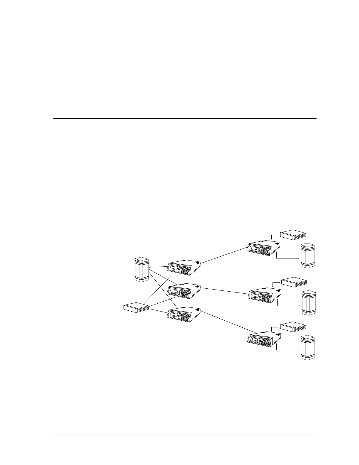
Chapter 1. Introducing ATLAS FrameRelay
Router
PBX
Router
PBX
Router
PBX
PBX
ATLAS800
Router
PLUS
T1
Fr ame
Relay
DDS
DDS
DDS
Figure 1-2. Frame Relay Circuit
The ATLAS Frame Relay/Router option allows the ATLAS series of Integrated Access Devices to act as a voice/data frame relay access device
(FRAD), a private network frame relay switch, a frame relay concentrator,
and an internal IP router. In addition, the ATLAS Frame Relay/Router option manages currently available bandwidth and switching applications.
FRAME RELAY FEATURES
The Frame Relay/Router option provides the following functions:
• Routes Internet Protocol(IP)trafficbetweenapublic or private framerelay network and the integral 10BaseT Ethernet port.
• Concentrates IP traffic from a public or private frame relay network to
one or more serial ports (V.35). The protocol passed over the serial port
is frame relay.
• Passes Systems Network Architecture (SNA), Bisync, and other legacy
protocols between a public or private frame relay network and an external DTE running frame relay to ATLAS. (May require the HDLC Module—P/N 1200222L1.)
• Performs voice compression/decompression (G.723.1)and interfaces to
either a Private Branch Exchange (PBX) or the Public Switched Telephone Network (PSTN). (This feature requires an additional option
module, the VCOM Module—P/N 1200221L1.)
SPECIFICATIONS
Table 1-1 lists the specifications for the frame relay features.
1-2 ATLAS Frame Relay User Manual 61200263L1-1.1
Page 15

Option Feature Specification
Frame Relay
Chapter 1. Introducing ATLAS Frame Relay
Table 1-1. Frame Relay Specifications
Packet throughput 7000 pkts/sec (minimum)
IP Routing
Management signaling
interfaces
UNI (user and network)
NNI
Management signaling types ANSI T1.617-D (Annex D)
ITU-T Q.933-A (Annex A)
LMI (Group of four)
Auto
Encapsulation RFC 1490 for IP and LLC2
PVC support 1000 PVCs
Congestion control FECN / BECN
Discard eligible (DE)
Quality of service (QOS) Prioritization on a per-PVC basis
Testing (ADTRAN proprietary) PVC loopback
Round trip delay measurement
SNMP support RFC 1315
Route discovery RIP V1
Voice Compression
RIP V2
ICMP
ARP
IARP
UDP Relay
OSPF
Virtual connections supported 100 PVCs
SNMP support MIB II
Algorithm G.723.1 or Netcoder (proprietary)
Number of channels supported Up to 64 compression channels
PCM coding MU-Law, A-Law (future)
Fax support 9600 bps
DTMF generation and
TIA 464A
detection
61200263L1-1.1 ATLAS Frame RelayUser Manual 1-3
Page 16

Chapter 1. Introducing ATLAS FrameRelay
1-4 ATLAS Frame Relay User Manual 61200263L1-1.1
Page 17

Chapter 2
OSI MODEL
Technology Overview
This chapter discusses the OSI Model, Frame Relay Protocol, and Transparent Bit Oriented Protocol (TBOP).
The Open Systems Interconnection (OSI) model is an internationally accepted standard forcommunication between multiple vendors’ communication
equipment. It relies on a seven-layer model to allow communication between communication equipment. Table 2-1 describes these layers.
Table 2-1. Seven-Layer OSI Model
Layer Title Description
Layer 7 Application Contains functions for end-user services. These
include FTP, remote file access, andnetwork
management. This is not the application, but the
interface.
Layer 6 Presentation Provides transparent communication by creating
code and syntax compatibility between systems.
Layer 5 Session Takes care of the communication facility
providedby the transport layer (layer 4). Allows
sessions to be established, recovered, and
terminated.
Layer 4 Transport Provides some error correction and end-to-end
flow control. Also decides best routefor the
information being transmitted.
Layer 3 Network Determines the method for transmitting data and
also deals with routing the data between
networks. Moves data based on addressing.
Layer 2 Data Link Deals with procedures and protocols for
controlling the transmission line. Provides some
error detection and correction.
Layer 1 Physical Deals with the electrical, mechanical, and
functional control of sending data over the
transmission lines.
61200263L1-1.1 ATLAS Frame Relay User Manual 2-1
Page 18

Chapter 2. Technology Overview
By definingstandardinterfacesbetweeneachof the seven layers, an individual layer only has to know about the interface to the layer above, to the layer
below, and to the same layer on the other end of the network. This interface
definition simplifies the process of networking.
TheRouterandFrameRelaysoftwareinATLASinvolveslayer3andlayer2
data processing. The OSI model is not limited to digital data networks, but
canbeextendedtosuchnetworksastheU.S.PostalService.Theexamples
belowshouldclarifytherolesofthefirstthreelayersandhowtheyinterface
with each other. Example 1 relates the OSI model to the process of mailing a
letter.
Example 1: OSI Model Related to Process of Mailing a Letter
Upper Layers Letters and Advertisements
Layer 3 Network Envelopes and Boxes
Layer 2 Data Link Mailbags
Layer 1 Physical Planes and Trucks
Send Process Receive Process
Person A writes a letter. Upper Layers Person B reads the letter.
Person A placesthe letter in
an envelope, addresses it to
person B, and puts envelope
in mailbox.
The envelope is collected
from mailbox and placed
into a mailbag destined for
post office B.
A truck takes the mailbag
and drives to post office B.
Since the postal service specifies how mail is t ransferred betweenlayers,the
person addressing the letter only needs to know the address of the person
receiving the letter to pass the letter down to the next layer. The letter writer
has no knowledge of the details of mailbags and moving letters between
post offices, but knows to place the letter in the mailbox so that the post office delivers the letter to the reader. The lower layers have no knowledge of
the letter, but take responsibility for getting it to the appropriate location.
Layer 3
Layer 2
Layer 1
Roads and
Interstates
Person B opens envelope
and removes the letter.
The mailbag is opened and
the en velope is placed in
person B’s post office box.
The truck delivers the
mailbag to post office B.
2-2 ATLAS Frame Relay User Manual 61200263L1-1.1
Page 19

Chapter 2. Technology Overview
Example 2: OSI Model Related to Process of Moving Data
Packet
A more typical example of the OSI model involves moving a data packet
across an IP network.
Upper Layers E-mail message
Layer 3 Network - IP/IPX
Layer 2 Data Link - FrameRelay/PPP
Layer 1 Physical - T1/DDS
Send Process Receive Process
Creates a data packet. Upper Layers Data packet is processed.
FRAME RELAY
Wraps the data in an IP
packet, specifies the IP
address of the far end
computer,anddetermines the
appropriate route.
TheIPpacketisplacedinside
aframerelaypacketwiththe
appropriate DLCI and placed
on the correct DS-1.
The frame relaypacket is
placed in the appropriate
DS0s.
Frame relay is one of several layer 2 (data link)protocolsthattransportdata
across a serial data network. These protocols also include Point-to-Point Protocol (PPP) and High-level Data Link Connection Protocol (HDLC). Frame
relay networks are composed of virtual circuits that connect customer locations. To reduce a customer’s overall monthly connection, multiple virtual
circuits could be delivered to the customer’s location over a single physical
connection.
Layer 3
Layer 2
Layer 1
LEC and IXC
The IP wrapper is
removed and the data is
then passed to the upper
layers.
The frame packet is
unwrapped and the IP
packet is sent to layer 3.
The frame relaypacket is
removed and passed to
layer 2.
Virtual Circuits
Virtual circuits can be either permanent (PVC) or switched (SVC). PVC
bandwidths are determined when the circuit is ordered from the frame relay
provider. PVCs are always active, even when no data is being transmitted.
SVC bandwidths are created and used only when needed and allow for negotiation of the bandwidth parameters during the circuit setup. SVCs are
currently unavailable from most frame relay providers, and ATLAS only
supports PVCs.
61200263L1-1.1 ATLAS Frame RelayUser Manual 2-3
Page 20
Chapter 2. Technology Overview
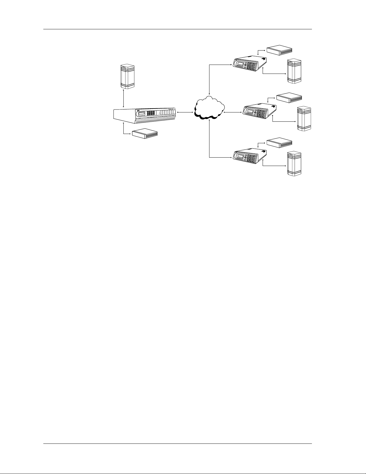
PVC Physical Connections
Figure 2-1 illustrates three PVCs being delivered over one physical circuit.
The frame relay switch within the frame relay provider’s circuit makes a
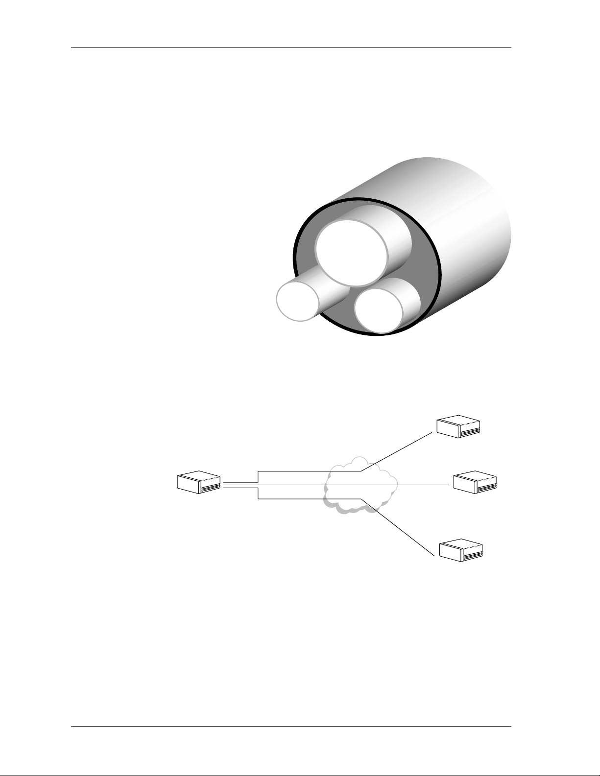
physical connection for each PVC. Each of the PVCs could connect to a different physical location at the other endofthe circuit. Figure 2-2 illustrates a
frame relay network topology.
PVC Z
32 kbps
PVC X
768 kbps
PVC Y
128 kbps
A
FrameRelay/Router
Figure 2-1. Three Virtual Circuits in One Physical Circuit
B
FrameRelay
Network
Virtual circuit X
Virtual circuitY
Virtual circuit Z
FrameRelay/Router
C
FrameRelay/Router
D
FrameRelay/Router
Figure 2-2. Frame Relay Network using Virtual Circuits
2-4 ATLAS Frame Relay User Manual 61200263L1-1.1
Page 21
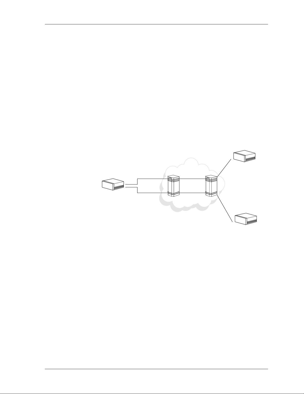
Data Link Connection Identifier (DLCI)
An address called a Data Link Connection Identifier (DLCI) uniquely identifies each of the virtual circuits in the frame relay network. A DLCI does not
address the equipment at the far end of the virtualcircuit, but addresses the
next piece of frame relay equipment within the network. The next piece of
frame relayequipment nowbecomesresponsiblefortransportingallframes
from the incoming port to the appropriate outgoing port.
Figure 2-3 illustrates a network using DLCI assignments. In this example,
the router at site A sends a frame packet to site B, by placing the data on
DLCI 100. Knowingthat all packets coming in DLCI 100 must go out DLCI
225, Frame Relay Switch A places the packets on DLCI 225 and sends them
out to Frame Relay Switch B. Frame Relay Switch B then takes the frame
packets from DLCI 225 and places them on DLCI 35 for delivery to the site
B router. From this example, you can see that each piece of frame relay
equipment only knows about the DLCIs local to it. Hence, you will hear
“DLCIs only have local significance.”
Chapter 2. Technology Overview
B
A
FrameRelay/Router
User-to-Network Interface
The interface between the customer and the frame relay switch is called the
User-to-Network Interface (UNI). Three different types of signaling can
transmit across this interface: LMI (Group of Four), Annex A
(ITU-T Q.933-A), and Annex D (ANSI T1.617-D). Unfortunately, due to signaling differences among the three types, they are incompatible with one another, and DLCI assignments vary among the three types. Tables 2-2 and
2-3 give the assignments for the three types.
DLCI 100
DLCI 200
FrameRelay/Router
FrameRelay
Switch A
DLCI 225
DLCI 650
FrameRelay
Switch B
DLCI 35
DLCI 501
C
FrameRelay/Router
Figure 2-3. Network Using DLCI Assignments
61200263L1-1.1 ATLAS Frame RelayUser Manual 2-5
Page 22

Chapter 2. Technology Overview
Local Management Interface (LMI)
LMI is the standard published by the Frame Relay Consortium in 1990 to
create a defined interface on the UNI. The Consortium, composed of Cisco
Systems,DEC,Nortel,andStrataCom, is commonlyreferredtoas the Group
of Four.
Annex A and Annex D
The International Telecommunications Union Telecommunication StandardizationSector(ITU-T) adoptedAnnexAa s the interface standardforinternational frame relay applications. The American National Standards
Institute(ANSI) modified theFrameRelayConsortium’sinterface specification and ratified it as Annex D—an interface standard for the United States.
Table 2-2. LMI (Group of Four) DLCI Assignments
DLCI Use
0 Call control signaling channel.
1-15 Reserved for future use.
16-1007 Available for customer data.
1008-1022 Reserved for future use.
1023 LMI channel.
Committed Information Rate (CIR)
Customers can order a circuit with a guaranteed amount of bandwidth for
their virtual connections. This amount is called the Committed Information
Rate (CIR), and it defines how muchbandwidth the customer is guaranteed
during normal network operation. Any data transmitted above this purchased rate is discard eligible (DE) by the network. That is, this data can be
discarded in the event of network congestion.
TheCIRcanbethoughtofasthesizeofthevirtualconnectionfromendto
end. The CIR canbe purchased in different increments up to the wire speed
of the slowest link. For example, if the circuit in Figure 2-3 had T1 access
fromsiteAtotheframerelaynetworkanda56-kbpsDDSlinefromsiteBto
the frame relay network, the largest CIR available for purchase would be
Table 2-3. Annex A and Annex D DLCI Assignments
DLCI Use
0 Carries frame relay signaling (LMI channel).
1-15 Reserved for future use.
16-991 Available for customer data.
992-1007 Management DLCIs for layer 2.
1008-1022 Reserved for future use.
1023 Higher layer protocol communication channel.
2-6 ATLAS Frame Relay User Manual 61200263L1-1.1
Page 23
56k. Although data could burst from site A to the frame relay network at the
full T1 speed of 1.536 Mbps, it would queue up in the frame relay network
until it could be sent across the 56-kbps DDS circuit. This queue could cause
network congestion.
Managing Network Congestion
If congestion becomes a problem within the network due to excessive data
being delivered fromoneofthesites, theframerelayswitchattemptstoflow
control the data by sending bits that notify networkdevices that transmissions in the opposite direction are congested. These bits are called Backward
Explicit Congestion Notification (BECN) and Forward Explicit Congestion
Notification (FECN).
Forexample,ifa frame relayswitchbeginsto experience congestion, itsends
the upstreamsiteaFECNand the downstream site aBECN.Thisnotification
indicates to the frame relay equipment that the frame relay switch is experiencingdifficultyandthat the framerelay device shouldbegin to flowcontrol
its traffic.
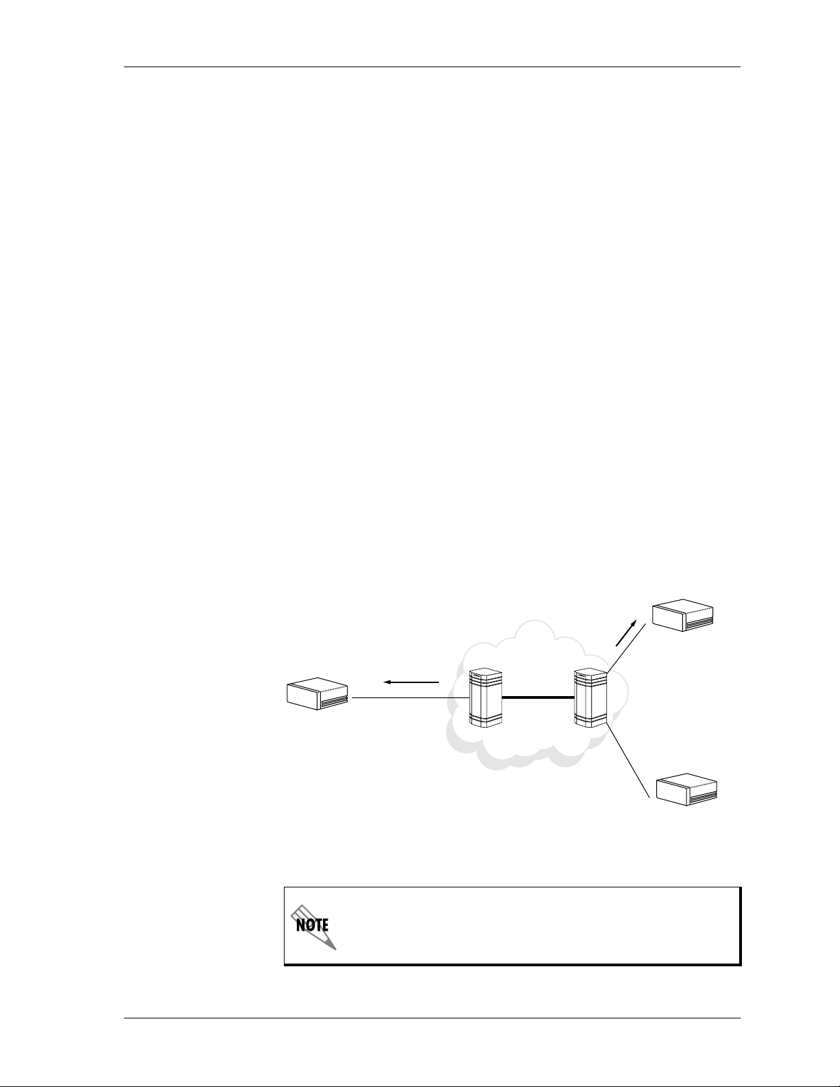
Figure 2-4 shows an example of FECN and BECN messagesbeing transmitted to the frame relayequipment when congestion occurs. Both ends are notified that congestion isoccurringwithintheswitch.Youmightwonderwhy
the receiving end should receive notification of congestion and then flow
control its data when the other end is causing the problem by sending large
amountsofdata.Flowcontrol is used by thereceivingendsothatupper layer acknowledgments from the destination slow down, thereby reducing the
amount of data being transmitted from the source.
Chapter 2. Technology Overview
Data Source
FrameRelay/
Router
Data Destination
N
C
FE
FrameRelay/Router
Switch Congestion
BECN
Frame
Switch
Frame
Switch
FrameRelay/Router
Figure 2-4. Network Congestion and Flow Control
This overview is not intended to beall inclusive of the operation of
a frame relay network. It is intended to help simplify the frame
relay configuration within ATLAS.
61200263L1-1.1 ATLAS Frame RelayUser Manual 2-7
Page 24

Chapter 2. Technology Overview
TBOP
Transparent Bit Oriented Protocol (TBOP) is an ADTRAN-proprietary
protocol that is used to transmit HDLC-formatted traffic across the frame
relay network. TBOP allows the transportation of protocols “unknown” to
ATLAS to be encapsulated in frame relay and sent to a remote location via
frame relay. This protocol can be useful in transporting other vendors’
proprietary protocols across the WAN.
ATLAS accepts HDLC-formatted data on one of the V.35 or T1 ports and
forwards that data across a frame relay network to another ATLAS or an
ADTRAN frame relay device (for instance, if ATLAS is communicating with
an IQ product).
PPP
The Point-to-Point Protocol, PPP, is the Internet standard for the transmission of IPpacketsoverseriallines. PPP is not confined to serial links though;
it runs on async or sync lines. PPP is also a multi-protocol transport mechanism. This means that PPP transports several differenttypes of other protocols: IP, IPX, Appletalk, Bridged Ethernet, etc. All of these protocols can be
transported at the same time. There are various compression protocols to increase the transmission rate of the link. The ATLAS only supports the IP
protocol over dedicated links. As per RFC 1661, PPP comprises three main
components:
1. A method for encapsulating multi-protocol datagrams.
2. A Link ControlProtocol(LCP)forestablishing,configuring, and testing
the data-link connection.
3. A family of Network Control Protocols (NCPs) for establishing and
configuring different network-layerprotocols (such as IP).
Link Control Protocol
To be portable to a wide variety of environments, PPP provides an LCP. The
LCP is used to automatically agree upon the encapsulation format o ptions,
handle varying limits on sizes of packets, detect a looped-back link and other common misconfiguration errors, and terminate the link. Other optional
facilities provided are authentication of the identity of its peer on the link,
and determination of when a link is functioning properly and when it is failing.
Network Control Protocols
Point-to-Point links tend to exacerbate many problems with the current
family of network protocols. For instance, assignment and management of
IP addresses, which is a problem even in LAN environments, is especially
difficult over circuit-switched point-to-point links (such as dial-up modem
servers).Theseproblems are handledbyafamily ofNCPs,andeach manage
the specific needs required by their respective network-layer protocols.
2-8 ATLAS Frame Relay User Manual 61200263L1-1.1
Page 25
Chapter 3
Enabling Frame Relay
The Frame Relay upgrade for the ATLAS 800
• ATLAS Software Activation Request Fax Form
• ATLAS Frame Relay User Manual
• Alphanumeric temporary license key
The temporary license key enables the Frame Relay software for 30 continu-
ous days of operation. Within this 30-day period, you must fax the registration sheet to ADTRAN with the upgraded unit’s serial number. A unique,
permanent software key for the upgradedATLAS is then faxed back to you.
If a permanent license key is not installed within 30 days, the Frame
Relay portion of ATLAS will cease operation.
If a temporary license key expires before the permanent license key is
installed, the system willreboot and all frame relay configuration
will be lost.
PLUS
includes the following:
61200263L1-1.1 ATLAS Frame Relay User Manual 3-1
Page 26
Chapter 3. Enabling Frame Relay
INSTALLING THE TEMPORARY LICENSE KEY
Instructions for Installing the Temporary License Key
Step Action
1 Select S
2 Select L
3 Select F
Under L
4
license for 30 days.
Enter the serial number on the registration sheet into the S
5
N
UMBER
YSTEMCONFIG
ICENSES
RAMERELAY
ICENSECODE
from S
field.
from the ATLAS main menu.
YSTEMCONFIG
.
, enter F
RAMERELAY
After installing the temporary license key, you must reboot the
system to enable Frame Relay. ATLAS will automatically prompt
for a reboot when a Frame Relay license key is installed.
OBTAINING THE PERMANENT LICENSE KEY
To obtain a permanent license key, complete the Fax Form and fax it to
ADTRAN at (256) 963-8030.
.
to enable thetemporary
ERIAL
Instructions for Completing the Fax Form
Step Action
a
Telnet
from S
1
S
F
Revision
Find the product number located on the outside of the unit, and
2
enter it into the field
Optional:
information to ADTRAN about how you are using the
3
ATLAS 800
a. A Telnet utility is provided on the ADTRAN Utilities diskettes that come with
the ATLAS 800
to your ATLAS unit and locate the following information
YSTEMINFO
ERIALNUMBER
IRMWAREREVISION
:
: Enter into the field
: Enter into the field
System Serial Number
ATLAS Chassis Software
.
ATLAS Chassis Part Number.
Fill in
PLUS
PLUS
unit. See the
Application Used (Optional)
.
ATLAS User Manual
. This field provides
for instructions.
.
3-2 ATLAS Frame Relay User Manual 61200263L1-1.1
Page 27
INSTALLING THE PERMANENT LICENSE KEY
Instructions for Installing the Permanent License Key
Step Action
Chapter 3. Enabling Frame Relay
1 Select S
2 Select L
3 Select F
Enter the license key faxed from ADTRAN into the L
4
field.
Enter the serial number faxed from ADTRAN into the S
5
N
Continuously press the left arrow key until you see a message
6
asking to confirm the change. Enter Y.
End the Telnet session and reconnect to the unit. The S
7
under S
YSTEMCONFIG
ICENSES
RAMERELAY
UMBER
field.
YSTEMCONFIG/LICENSES
from S
from the ATLAS main menu.
YSTEMCONFIG
.
.
now reads P
ERMANENT
If the frame relay featurewas not previously enabled, the system will
automatically reboot to enable the new feature.
ICENSECODE
ERIAL
TATUS
field
.
If a temporary key expires before the permanent key is installed, the
system will automatically reboot, and all frame relay configuration
will be lost.
61200263L1-1.1 ATLAS Frame RelayUser Manual 3-3
Page 28

Chapter 3. Enabling Frame Relay
3-4 ATLAS Frame Relay User Manual 61200263L1-1.1
Page 29

Chapter 4
OVERVIEW
Defining Packet Endpoints
A packet endpoint is a virtual port within ATLAS into which a specified
physical port (a T1 or an Nx56/64) terminates its data for furth er routing by
the system. All packet services, including frame relay or PPP, must have defined packet endpoints. The P
used to define packet endpoints.
Your frame relay provider furnishes specific information on defining the
packet endpoint. This information includes signaling type (Annex A,
Annex D, or LMI) and definitions for all active PVCs. The P
submenu map connects protocols from packet endpointto packet endpoint.
For PPP, the only information needed is IP address and user name/password.
In addition to defining packet endpoints, you must also configure the physical port before it can run frame relay (see Chapter 5).
For a detailedlook at configuring frame relay connections, refer to Chapter
6, Frame R elay ConfigurationExamples.
ACKETMANAGER
menu contains submenus
ACKETCNCTS
PASSWORDS
You must have the appropriate password leveltoedit items using the terminal menu. Security level 1 users can view and edit every available field. Security level 5 users can view any field, but they cannot edit. (See the section
Access Passwords in the ATLAS 800
on working with passwords.)
PLUS
UserManualfordetailed information
NAVIGATING THE TERMINAL MENUS
ATLAS uses hierarchical menus to access all of its features. All menus display in the terminal window. The top-most menu level (in this case, the
P
ACKETMANAGER
NCTSSORT
C
fer to the ATLAS 800
navigate through the terminal menu.
61200263L1-1.1 ATLAS Frame Relay User Manual 4-1
) leads to submenus (P
RAMERELAY
,andF
PLUS
User Manual for detailed instructions on how to
IQ) which are grouped by functionality.Re-
ACKETENDPNTS
ACKETCNCTS
, P
,
Page 30
Chapter 4. Defining Packet Endpoints
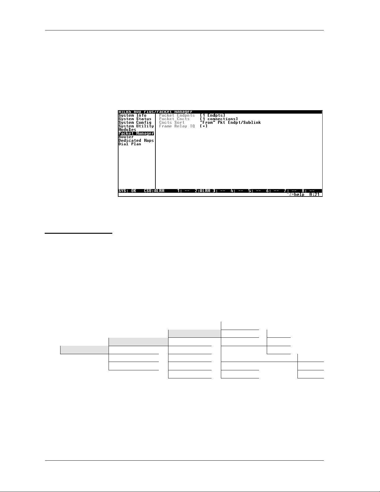
THE PACKET MANAGER MENU
ACKETMANAGER
The P
layer 2 connections, including frame relay endpoints. These submenus, discussed in this chapter, include P
ORT
.TheF
S
discussed separately in Chapter 6.
RAMERELAY
submenus (see Figure 4-1) define and configure all
ACKETENDPNTS
ACKETCNCTS
, P
,andC
NCTS
IQ sub menu provides frame relay statistics and is
Figure 4-1. Packet Manager Menu
P
ACKETENDPNTS
STATUS
Packet Endpnts Performance Sig Role Network
Packet Manager Packet Cncts Config Both
Cncts Sort Test Sig Type AnnexA
Frame Relay IQ Endpnt Count Active AnnexD
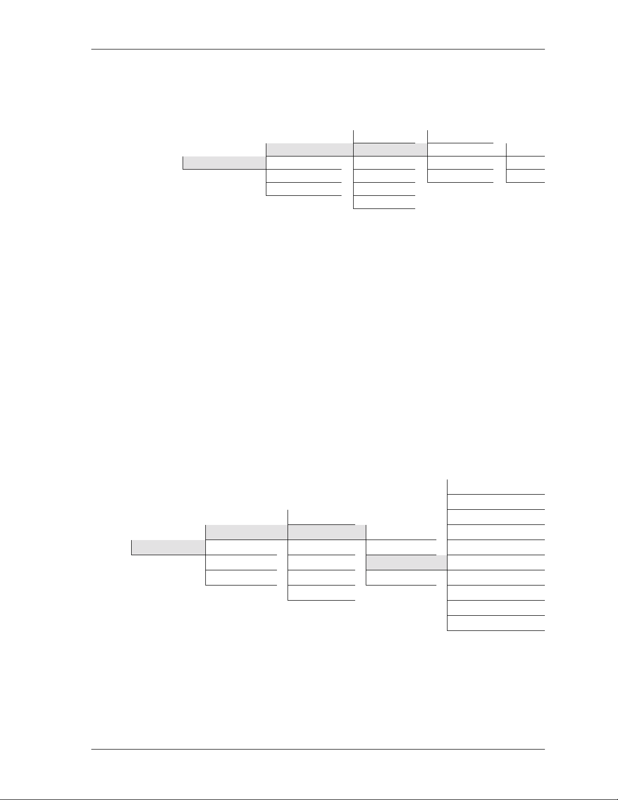
ACKETENDPNTS
The P
Submenus include S
NDPNTSSORT
and E
TATUS
S
submenus display the status of each packet endpoint including the
packet endpoint name (E
ing role (S
TIVE
IGROLE
), and the connections (C
menu defines, monitors, and tests a packet endpoint.
TATUS
ERFORMANCE
, P
.
NDPNTNAME
), the signaling type (S
URRENTPORT
), the protocol type (P
IGTYPE
each of these fields. Figure 4-2 shows the S
Endpnt Name
Status Prot User
Endpnts Sort Current Port LMI
ONFIG
, C
). The following sections discuss
TATUS
EST
, T
NDPNTCOUNT
, E
ROT
), the signal-
), the signaling activity (A
menu tree.
,
C
-
Figure 4-2. Status Menu Tree
NDPNTNAME
E
4-2 ATLAS Frame Relay User Manual 61200263L1-1.1
Read Security: 5
Displays the packet endpoint name as defined in the P
ONFIGMENU
C
(also see Config on page 4-9).
ACKETENDPNTS
/
Page 31

Chapter 4. Defining Packet Endpoints
ROT
P
S
IGROLE
IGTYPE
S
Read Security: 5
Displays the layer 2 protocol that this packet endpoint terminates. FR indicates that this packet endpoint is configured for frame relay. TBOP indicates that this packet endpoint is configured for Transparent Bit Oriented
Protocol (TBOP). PPP indicatesthispacketendpointisconfiguredforthe
Point-to-Point Protocol.
Read Security: 5
Displays the frame relay signaling role for this packet endpoint. The following options indicate the signaling role this packet endpoint is performing.
These settings are not applicable for PPP.
U
SER
Indicates user side of the User to Network Interface (UNI).
N
ETWORK
Indicates netwo rk side of the UNI interface.
B
OTH
Indicates that the packet endpoint is operating in Network-to-Netw ork
Interface (NNI) mode.
Read Security: 5
Displays the frame relay signaling type used on this packet endpoint. These
settings are not applicable for PPP.
CTIVE(FRAME
A
ELAY
R
)
A
CTIVE
(PPP) This indicates the status of the PPP negotiation.
A
NNEX
A
Signaling using ITU-T Q.933-A.
NNEX
A
D
Signaling using ANSI T1.617-D.
LMI
Signaling using Group of Four.
Read Security: 5
Indicates that there is active frame relay signaling on this packet endpoint.
The packet endpoint must be defined by the frame relay configuration settings to show active frame relay signaling.
NITIAL
I
This is the first state of the LCP negotiation. This will usually go directly to
the starting state to start the PPP negotiation, unless the packet endpoint
has not been tied to a physical port in the dedicated maps.
S
TARTING
This packet endpoint is in this state when the physical line is down.
61200263L1-1.1 ATLAS Frame RelayUser Manual 4-3
Page 32

Chapter 4. Defining Packet Endpoints
REQ-S
This packet endpoint is in this state when an LCP configuration request has
been sent to the peer.
CK-RCVD
A
This packet endpoint is in this state when we have received an "acknowledge" from the peer for our configuration request.
CKSENT
A
This packet endpoint is in this state when we have acknowledged the
peer’s configuration request and he has not acknowledged us.
PENED
O
This packet endpoint is in this state when LCP negotiation has finished;
authentication, if enabled, is occurring now.
LOSING
C
This packet endpoint is in this state when we have sent the peer a "terminate" request and are waiting for the peer’s acknowledgement.
LOSED
C
This packet endpoint is in this state when we have received the peer’s
acknowledgement to our terminate request; this will go to the initial state.
ENT
URRENTPORT
C
TOPPING
S
This packet endpoint is in this state when we have received a terminate
request from the peer.
TOPPED
S
This packet endpoint is in this state when we have acknowledged the
peer’s terminate request.
OTCONNECTED
N
This packet endpoint is in this state when the packet link has not yet been
connected to the router.
Read Security: 5
Displays the connections for the packet endpoint. The letter
indicates that this packet endpoint is used in the P
ACKETCNCTS
U
in this field
map (also
see Packet Cncts on page 4-22). The remainder of the fieldindicates the
physical port to which this packet endpoint is connected, as defined in the
D
EDICATEDMAP
(also see Dedicated Maps on page 5-1). If the port is a chan-
nelized interface such as a T1, the DS0 assignment is also provided.
4-4 ATLAS Frame Relay User Manual 61200263L1-1.1
Page 33
Chapter 4. Defining Packet Endpoints
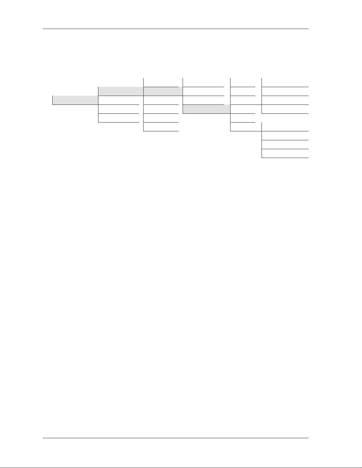
PERFORMANCE
NDPNTNAME
E
ROTOCOL
P
Displays performance information for each packet endpoint including E
PNTNAME
(endpointname),P
ROTOCOL
INKSTATS
, L
,andS
UBLINKSTATS
themenutreeinFigure4-3).
Status Endpnt Name
Packet Endpnts Performance Protocol FR
Packet Manager Packet Cncts Config Link Stats TBOP
Cncts Sort Test Sublink Stats PPP
Frame Relay IQ Endpnt Count
Endpnts Sort
Figure 4-3. Performance Menu Tree
Read Security: 5
Displays the packet endpoint name as defined in PACKET
NDPNTS/CONFIG
E
(also see Config on page 4-9).
Read Security: 5
Displays the layer 2 protocol that this packet endpoint terminates as
defined in P
ACKETENDPNTS/CONFIG
(also see Config on page 4-9).
ND
(see
-
INKSTATS
L
RAMERELAY
(F
Read Security: 5
This field is dependent on the type of protocol selected inP
)
ONFIG
C
(also see Config on page 4-9).Displayslayer2 performance statistics
ACKETENDPNTS
(see Figure 4-4). The statistics fields for frame relay reflect the total count
since last cleared. Descriptions for each of these fields begin following the
menu tree.
Tx Packets
Rx Packets
Status State Changes
Packet Endpnts Performance Endpnt Name Signaling Errors
Packet Manager Packet Cncts Config Protocol Signaling Timeouts
Cncts Sort Test
Frame Relay IQ Endpnt Count Sublink Stats Full Status Rx
Endpnts Sort Link Integrity Status Tx
Link Stats (FR) Full Status Tx
Link Integrity Status Rx
Clear Counters
Figure 4-4. Frame Relay Link Stats Menu Tree
/
XPACKETS
T
Total number of frame relay packets transmitted through this packet endpoint, including both user data (on all PVCs) and signaling.
61200263L1-1.1 ATLAS Frame RelayUser Manual 4-5
Page 34

Chapter 4. Defining Packet Endpoints
ACKETS
RXP
Total number of frame relay packets received through this packet endpoint
(on all PVCs).
TATECHANGES
S
Totalnumber of times thatframerelay signalinghasgone activeorinactive.
IGNALINGERRORS
S
Total number of signaling frames received with PVC signaling protocol violations.
IGNALINGTIMEOUTS
S
Number of times signaling polls were not received in the time specified in
T391 in the P
ULLSTATUSTX
F
Number of full status polls transmitted by this packet endpoint.
ULLSTATUSRX
F
Number of full status polls received by this packet endpoint.
INKINTEGRITYSTATUSTX
L
Number of link integrity polls transmitted by this packet endpoint.
ACKETENDPNTS/CONFIG
menu (also see Config on page 4-9).
INKINTEGRITYSTATUSRX
L
Number of link integrity polls received by this packet endpoint.
LEARCOUNTERS
C
Clears all values in this submenu.
INKSTATS
L
(TBOP)
Read Security: 5
This field is dependent on the type of protocol selected inP
ONFIG
C
(also see Config on page 4-9).Displayslayer 2 performance statistics
(seethemenutreeinFigure4-5).ThestatisticsfieldsforTBOPreflectthe
total count since last cleared.
Status
Packet Endpnts Performance Endpnt Name
Packet Manager Packet Cncts Config Protocol Tx Packets
Cncts Sort Test
Frame Relay IQ Endpnt Count Sublink Stats ClearCounters
Endpnts Sort
Link Stats (TBOP) RxPackets
Figure 4-5. TBOP Link Stats Menu Tree
ACKETENDPNTS
/
XPACKETS
T
Displays the total number of HDLC packets transmitted through this
packet endpoint.
4-6 ATLAS Frame Relay User Manual 61200263L1-1.1
Page 35

Chapter 4. Defining Packet Endpoints
ACKETS
RXP
Displays the total number of HDLC packets received through this packet
endpoint.
LEARCOUNTERS
C
Clears all values in this submenu.
INKSTATS
L
(PPP)
Read Security: 5
This field is dependent on the type of protocol selected inP
ONFIG
C
(also see Config on page 4-9).Displayslayer2 performance statistics
ACKETENDPNTS
(see Figure 4-6). Descriptions for each of these fields begin following the
menu tree.
Status
Packet Endpnts Performance Endpnt Name LCP State
Packet Manager Packet Cncts Config Protocol IPCP State
Cncts Sort Test
Frame Relay IQ Endpnt Count Sublink Stats Rx Packets
Endpnts Sort Clear Counters
Link Stats (PPP) Tx Packets
Figure 4-6. PPP Link Stats Menu Tree
TATE
LCP S
This reflects the LCP layer state.
IPCP
This shows the UP if PPP IP control has negotiated successfully.
/
XPACKETS
T
Number of packets transmitted over this link.
XPACKETS
R
Number of packets received over this link.
LEARCOUNTERS
C
Resets the Tx packets and Rx packets.
61200263L1-1.1 ATLAS Frame RelayUser Manual 4-7
Page 36
Chapter 4. Defining Packet Endpoints
UBLINKSTATS
S
Read Security: 5
Displays frame relay performance statistics for supported packet endpoint
sublinks(seethemenutreeFigure4-5).Thesestatisticsfieldsreflectthe
total count since last cleared. These settings are not applicable for PPP.
Status Endpnt Name Name Up
Packet Endpnts Performance Protocol DLCI Down
Packet Manager Packet Cncts Config Link Stats State Up/Bu
Cncts Sort Test
Frame Relay IQ Endpnt Count Rx Pckts
Endpnts Sor t Statistics BECN Count
Sublink Stats Tx Pckts Down/Bu
DE Discard Count
FECN Count
Reset Counters
Figure 4-7. Frame Relay Sublink Stats Menu Tree
AME
N
User-defined name of a sublink (PVC).
DLCI
DLCI for sublink as defined in P
ACKETENDPNTS/CONFIG
(also see Config on
page 4-9).
TATE
S
Indicates if this particular sublink (PVC) has been defined as active by a full
status poll, and also indicates if the PVC is in backup mode.
P
U
PVC is up (active).
OWN
D
PVC is down (inactive).
P/BU
U
PVC is up but in backup mode.
OWN/BU
D
PVC is down and in backup mode.
XPCKTS
T
Total number of frame relay user data packets transmitted over t his PVC.
XPCKTS
R
Total number of frame relay user data packets received over this PVC.
TATISTICS
S
Providesadditional information, as follows, on the individual sublink:
BECN C
OUNT
TotalnumberofBECNbitsreceivedonthisPVC.
4-8 ATLAS Frame Relay User Manual 61200263L1-1.1
Page 37

Chapter 4. Defining Packet Endpoints
ISCARDCOUNT
DE D
Total number of Discard Eligible bits that have been received on this
PVC.
CONFIG
FECN C
OUNT
Total number of FECN bits received on this PVC.
ESETCOUNTERS
R
Resets all sublink counters.
Creates and configures packet endpoints (see the menu tree in Figure 4-8).
Status Endpnt Name
Packet Endpnts Performance Protocol Frame Relay
Packet Manager Packet Cncts Config Config TBOP
Cncts Sort Test Sublinks PPP
Frame Relay IQ Endpnt Count Usage
Endpnts Sort
Figure 4-8. Config Menu Tree
NDPNTNAME
E
Write Security: 3; Read Security: 5
Simplifies configuration with user-definable names such as the name of the
frame relay provider or the circuit ID.
ROTOCOL
P
ONFIG
C
Write Security: 3; Read Security: 5
Defines the protocol operating on this port. F
RAMERELAY
configures this
packet endpoint to frame relay. TBOP configures this packet endpoint as
transparent bit oriented protocol. PPP configures this packet endpoint as
point-to-point protocol.
Write Security: 3; Read Security: 5
Displays the configuration for this packet endpoint. This menu is protocoldependent. TBOP requires no configuration. The selections for this menu
when Frame Relay is the protocol are listed in Config (Frame Relay as proto-
col) on page 4-10 and shown in Figure 4-9 , and the selections for this menu
when PPP is the protocol are listed in Config (PPP as protocol) on page 4-13
and shown in Figure 4-9.
61200263L1-1.1 ATLAS Frame RelayUser Manual 4-9
Page 38

Chapter 4. Defining Packet Endpoints
ONFIG(FRAMERELAY AS PROTOCOL
C
)
Figure 4-9 shows the selections for this menu when Frame Relay is the protocol.
Off
Status Endpnt Name Auto
Packet Endpnts Performance Protocol Signaling Role Both
Packet Manager Packet Cncts Config Config Network
Cncts Sort Test Sublinks User
Frame Relay IQ Endpnt Count Usage
Auto
Annex A
Signaling Type AnnexD
LMI
User Poll Timer (T391)
User Polls Per Status (N391)
User Bad Event Threshold (N392)
User Event Window Size (N393)
Net PollTimer(T391) Net Poll Response Timeout (T392)
Net Polls Per Status (N391)
Net Bad Events Threshold (N392)
Net Event Window Size (N393)
NNI mode only
Figure 4-9. Config/Config Menu Tre e (Frame Relay)
IGNALINGROLE
S
Defines whether this packet endpoint acts as the network or user side of the
UNI or as an NNI.
FF
O
Use when the remote device does not support frame relay signaling.
UTO
A
Detects the role of the device on the other end of the circuit and automatically sets this packet endpoint to the appropriate value.
OTH
B
Operates in NNI mode.
ETWORK
N
Acts as the network side of the UNI interface.
SER
U
Acts as the user side of the UNI interface.
4-10 ATLAS Frame Relay User Manual 61200263L1-1.1
Page 39

Chapter 4. Defining Packet Endpoints
Choosing the Signaling Role for Bac kup Links
Carefully choose the S
IGNALINGROLE
of a packet endpoint that is configured with backup sublinks. Please note that the ADTRAN IQ and Express
families of products do NOT support frame relay signaling on the backup
sublink.
For cases where... Set
IGNALING
S
OLE
R
to...
The backup sublink is connected to a switched network (e.g.,
FF
O
ISDN DBU), and the remote device DOES NOT support frame
relay signaling.
The remote device DOES support signaling on the backup
B
OTH
sublink.
The backup sublink is a dedicated connection to the remote
B
OTH
device, and the network is Private Frame Relay.
The backup sublink is a dedicated connection to the remote
U
SER
device, and the network is Public F rame Relay.
S
IGNALINGTYPE
Controls the frame relay signaling type that operates on this packet endpoint.
UTO
A
Detects the signaling type of the device on the other end of the circuit
and sets this packetendpoint to the same signaling type.
NNEX
A
A
Transmits and responds to ITU-T Q.933-A standards.
NNEX
A
D
Transmits and responds to ANSI T1.617-D standards.
LMI
Transmits and responds to Group of Four specifications.
SERPOLLTIMER
U
(T391)
Sets the polling interval to the network in seconds.
SERPOLLSPERSTATUS
U
(N391)
Controls how many link integrity polls occur between full status polls.
SERBADEVENTTHRESHOLD
U
(N392)
Sets the number of bad polling events that will cause the link to be declared
down in N393 Polls.
61200263L1-1.1 ATLAS Frame RelayUser Manual 4-11
Page 40

Chapter 4. Defining Packet Endpoints
SEREVENTWINDOWSIZE
U
Defines the number of poll events in each moni tored window.
(N393)
If the number of polls reaches N392 in any N393period, the link
will be declared down. When N393 good polls are received, the
link will be declared active again.
ETPOLLRESPONSETIMEOUT
N
(T392)
Determines how long this packet endpoint will wait without receiving a
poll before declaring the poll bad.
Ensure that this timer is greater than the T391 on the user side of
the UNI; otherwise, erratic behavior will result.
ETPOLLSPERSTATUS
N
(N391)
Sets the number of link integrity polls before a full status is transmitted.
ETBADEVENTSTHRESHOLD
N
(N392)
Sets the number of bad polling events that will cause the link to be declared
down in N393 Polls.
ETEVENTWINDOWSIZE
N
(N393)
Defines the number of poll events in each moni tored window.
IfthenumberofbadpollsreachesN392inanyN393period,the
link will be declared down. When N393 good polls are received,
the link will be declared active again.
4-12 ATLAS Frame Relay User Manual 61200263L1-1.1
Page 41

Chapter 4. Defining Packet Endpoints
ONFIG
C
(PPP
AS PROTOCOL
)
Figure 4-10 shows the selections for this menu when Frame Relay is the
protocol.
Rx Method
Status Endpnt Name Rx Authentication
Packet Endpnts Performance Protocol Authentication Rx User Name
Packet Manager Packet Cncts Config Config Rx Password
Cncts Sort Test Sublinks Tx Method
Frame Relay IQ Endpnt Count Usage Tx User Name
Tx Password
IP Mode
Debug Log LCPDebugging
IPCP Debugging
Authentication Debugging
Unknown Protocol Debugging
Max Config
Max Timer
Max Failure
Figure 4-10. Config/Config Menu Tree (PPP)
UTHENTICATION
A
ETHOD
RXM
Thesearethemethodswewillusetoauthenticatethepeer. N
selected when you do notwant to authenticate the peer.PAP, CHAP,
EAP is selected when you will allow the peer to be authenticated with
one of the listed authentication protocols. In this case, the most secure
method will be used first (EAP,thenCHAP,thenPAP). CHAP
is selected when you will authenticate the peer only using one of the
encryptedauthenticationprotocols. EAP is selected when you will
authenticate the peer only using the EAP authentication protocol.
XAUTHENTICATION
R
This selects the different types of authentication to use to authenticate
the peer. L
OCAL
is used when you want to use the local username and
password for this port to authenticate the peer. (In the future we will
have R
R
ADIUS
XUSERNAME
, to use a radius server to authenticate the peer.)
The username we use to authenticate the peer.
XPASSWORD
R
The password we use to authenticate the peer.
ONE
OR
is
OR
EAP
61200263L1-1.1 ATLAS Frame RelayUser Manual 4-13
Page 42

Chapter 4. Defining Packet Endpoints
TXM
These are the methods that we will allow the peer to authenticate us
with. This is of use when a peer wants to do PAP just to get your password. N
the peer. PAP, CHAP, or EAP is selected when you will let the peer use
one or all of the authentication protocols. CHAP or EAP is selected
when you will let the peer use only one of the encrypted authentication
protocols. EAP is selected when you will let the peer use only the EAP
authentication protocol.
XUSERNAME
T
The username that the peer uses to authenticate us.
XPASSWORD
T
The password that the peer uses to authenticate us.
IP
ODE
M
This turns the IPCP protocol ON or OFF
EBUGLOG
D
The following events can be viewed in the event log when PPP events have
been turned to 'Info'.
ETHOD
ONE
is selected when you do not want to be authenticated by
EBUGGING
LCP D
This turns on LCP negotiation debugging.
IPCP D
EBUGGING
This turns on IPCP negotiationdebugging.
UTHENTICATIONDEBUGGING
A
This turns on authentication debugging.
NKNOWPROTOCOLDEBUGGING
U
This turns on debugging for unknown protocols.
AXCONFIG
M
This valueis the numberof unanswered configuration-requests that should
be transmitted before giving up on the negotiation. The default value is 10.
AXTIMER
M
This value is the number of seconds to wait between unanswered configuration-requests. The default value is 2 seconds.
AXFAILURE
M
Due to the nature of PPP, configuration options may not be agreed upon
between two PPP peers. This value is the number of configuration-NAK's
that should occur before an option is configuration-rejected. This allows a
connection to succeed that might otherwise fail. The default value is 5.
4-14 ATLAS Frame Relay User Manual 61200263L1-1.1
Page 43

Chapter 4. Defining Packet Endpoints
UBLINKS
S
Write Security: 3; Read Security: 5
Allows PVC creation and configurationwithina frame relay link that uses sublink DLCIs (see Figure 4-11). Sublinks are not supported in TBOPor PPP.
In-band Sequence Number
Remote FECN Notification
React to BECN
Drop DE Packets when overloaded
Fragmentation Threshold
Fragmentation Size
DLCI State
Diagnostic Mode
Status EndpntName Primary | Backup Selection
Packet Endpnts Performance Protocol Enable Backup Support
Packet Manager Packet Cncts Config Config Name Backup Packet Endpt
Cncts Sor t Test Sublinks DLCI Backup Sublink
Frame Relay IQ Endpnt Count Usage QOS Primary Packet Endpt
Endpnts Sort Config Primary Sublink
Backup Mode
Switch on Sublink Down
a. Only available when the selection is Primary. Switch on LMI Inactive
b. Only available when the select ion is Backup. Switch on Backup Active
c. Only available when the selection is Primary Backup Delay in Seconds
with BackupSupportor Backup. RestoreDelayin Seconds
a
b
c
a
a
b
Figure 4-11. Sublinks Menu Tree
AME
N
User-defined name for the DLCI.
DLCI
Local address for each PVC as assigned by the carrier.
QOS
Quality of service. These values can be used to assign a guaranteed amount
of bandwidth available for this connection. The sum of all QOS values for
the sublink should not exceed the Committed Information Rate (CIR).
ONFIG
C
Allows configuration of parameters for each DLCI.
N-BANDSEQUENCENUMBER
I
This option will not appear when D
HROUGHDIAGNOSTICPACKETS
T
. All packets on this PVC will get a num-
IAGNOSTICMODE
is set to P
ASS
bered tag so that ADTRAN IQ products can detect lost packets in the
frame relay network. Only turn this option ON if there is an ADTRAN
IQ-capable product on the other end of the PVC.
61200263L1-1.1 ATLAS Frame RelayUser Manual 4-15
Page 44

Chapter 4. Defining Packet Endpoints
EMOTE
R
FECN N
OTIFICATION
If FECN is received on the interface, a notification is sent to frame relay
equipment on other end of the PVC.
EACT TO
R
BECN
If BECN is received, traffic to the frame relay network is flowed off.
D
ROP
ACKETS WHEN OVERLOADED
DE P
If traffic congestion occurs, discard eligible (DE) packets drop.
RAGMENTATIONTHRESHOLD
F
Defines the maximum data packet size that will be transmitted without
fragmenting the data to support voice. Table 4-1 provides suggested
values based on the PVC CIR.
RAGMENTATIONSIZE
F
Defines packet size when fragmentation is active.
Table 4-1. Suggested Fragmentation Values Based on the PVC CIR
PVC
CIR
Frag
Size
Frag
Threshold
PVC
CIR
Frag
Size
Frag
Threshold
64 56 112 832 1016 2032
128 136 272 896 1096 2192
192 216 432 960 1176 2352
256 296 592 1024 1256 2512
320 376 752 1088 1336 2672
384 456 912 1152 1416 2832
448 536 1072 1216 1496 2992
512 616 1232 1280 1576 3152
576 696 1392 1344 1656 3312
640 776 1552 1408 1736 3472
704 856 1712 1472 1816 3632
768 936 1872 1536 1896 3792
DLCI S
TATE
Controlshow the state of this DLCI isreported to any packet connections within ATLAS attempting to send or receive data on this DLCI.
UTO
A
Passes the state as reported by the frame relay switch. Set DLCI
STATE
ORCE UP
F
to A
UTO
for normal operation.
This DLCI disregards the status as reported from the switch and
reports ACTIVE
to all packet endpoints within ATLAS.
ORCE DOWN
F
Reports status as D
4-16 ATLAS Frame Relay User Manual 61200263L1-1.1
OWN
to all packet endpoints within ATLAS.
Page 45

Chapter 4. Defining Packet Endpoints
IAGNOSTICMODE
D
Controls operation of PVC testing options. To allow the far end to measure delay, select E
in-band delay, select I
ous diagnostic functions, select P
CHOFAR-ENDLOOPBACKS
E
CHOFAR-ENDLOOPBACKS
N-BAND DELAYMEASUREMENT
ASS-THROUGHDIAGNOSTICPACKETS
. To continuously measure
.Toturnoffcontinu-
.
Generates and transmits a response on this DLCI to the remote
equipment if an ADTRAN proprietary diagnostic message is
received on this DLCI.
N-BANDDELAYMEASUREMENT
I
Generates a diagnostic packet to measure delay through the frame
relay network. This process requires that the equipment at the
remote site be ADTRAN IQ compatible.
ASS-THROUGHDIAGNOSTICPACKETS
P
UsedwhenATLASisactingasaframerelayswitch.Transmitsa
diagnostic packet out the packet endpoint connected to this DLCI,
if a diagnostic packet is received on this packet endpoint.
RIMARY|BACKUPSELECTION
P
Allows you to define a sublink as a primary or a backup sublink. P
MARY
defines a normal sublink and includes the menus E
ACKUPSUPPORT
B
ACKUP
B
ACKETENDPT
P
defines a backup sublink and includes the menus P
ACKUPPACKETENDPT
, B
RIMARYSUBLINK
and P
,andB
.
ACKUPSUBLINK
NABLE
RIMARY
RI
-
.
NABLEBACKUPSUPPORT
E
Visible only if the sublink type is P
menus. NO
ACKUPPACKETENDPT
B
Visible only if E
ACKUPPACKETENDPT
B
hides the backup menus.
NABLEBACKUPSUPPORT
that contains the B
tied to this sublink.
ACKUPSUBLINK
B
Visible only if E
ACKUPSUBLINK
B
RIMARYPACKETENDPT
P
Visible only if B
NDPT
E
P
that contains the P
RIMARYSUBLINK
Visible only if B
NABLEBACKUPSUPPORT
to be tied to this sublink.
ACKUP
ACKUP
is selected. Selects the P
RIMARYSUBLINK
is selected. Selects the P
be tied to this sublink.
The fields B
ON
LMI I
ELAY INSECONDS
D
RIMARY
if P
ACKUPMODE
NACTIVE
(with B
WITCH ONBACKUPACTIVE
, S
,andR
ACKUPSUPPORT
WITCH ONSUBLINKDOWN
, S
ESTOREDELAY INSECONDS
RIMARY
. YESdisplays the backup
is set to YES. Selects
ACKUPSUBLINK
is set to YES. Selects the
RIMARYPACKET
to be tied to this sublink.
RIMARYSUBLINK
ACKUP
)orB
ACKUP
, B
is enabled.
to be
WITCH
, S
display
to
61200263L1-1.1 ATLAS Frame RelayUser Manual 4-17
Page 46

Chapter 4. Defining Packet Endpoints
ACKUPMODE
B
Provides switching options.
WITCH ONSUBLINKDOWN
S
Provides switching options if the sublink goes down. Select YESto
switch to backup if the primary sublink goes down, otherwise select
N
O
UTO
A
Provides normal operation.
ORCED
F
Forces a switch to backup.
ISABLED
D
Disables backup switching.
.
Sublinks Example
WITCH ON
S
LMI I
NACTIVE
Provides switching options for LMIsignaling. Select YESto switch to
backup if LMI signaling is inactive on the primary link, otherwise select
N
O
.
WITCH ONBACKUPACTIVE
S
Provides switching options ifthe backup sublink goes active. Select Y
ES
to switch to backup if the backup sublink goes active, otherwise select
O
.
N
ACKUPDELAY INSECONDS
B
The amount of time within which any of the enabled switch criteria
must be met before service is switched to the backup circuit.
ESTOREDELAY INSECONDS
R
Theamountoftimewithinwhichthecriteriaforswitchingtobackup
are reached before service is returned to the primary circuit.
Assume the followingsublink packet endpoint is connected to the frame relay network via a full T1:
Name DLCI QOS
Atlanta 903 768
New York 805 384
San Francisco 615 384
If the PVC to San Francisco needs to transmit data, it will be able to access
the network at full T1 rates. If, at the same time, data needs to be transmitted
to the PVC to New York, the San Francisco and New York PVCs would
equally share the T1 to the frame relay provider because they have the same
QOS value. If, also at the same time, data needed to be transmitted to the
PVC to Atlanta, the T1 would be divided three ways: traffic to Atlanta gets
half of the T1, and the New York and San Francisco PVCs equally share the
remaining half of the T1, since they share the same QOS value.
4-18 ATLAS Frame Relay User Manual 61200263L1-1.1
Page 47

Chapter 4. Defining Packet Endpoints
TEST
SAGE
U
Read Security: 5
This field displays a 7-character summary of the references to this link.
Each character can be a dash (-), or it can be a character indicating the
resource represented by the character position. The character positions follow:
1 Packet connection in the first dedicated connections map.
2 Packet connection in the second dedicated connections map.
3 Packet connection in the third dedicated connections map.
4 Packet connection in the fourth dedicated connections map.
5 Packet connection in the fifth dedicated connections map.
s Switched packet connection in the dial plan.
u Used by one or more packet switch connections or packet voice entries.
Packet voice entries are in either the
D
IALPLAN
on page 5-1.
EDICATEDMAPS
D
or the
Provides menus for controlling options and settings for packet endpoints
(seethemenutreeinFigure4-12).
Name
DLCI Start
Test ContDly
Status StopTst
Packet Endpnts Performance Duration
Packet Manager Packet Cncts Config Endpt Name Echo Pkt Tx
Cncts Sort
Frame Relay IQ Endpnt Count Sublink Echo Pkt Dropped
Test Protocol EchoPkt Rx
Endpnts Sort Results Rmt Pkt Dropped
[MN/AV/MX Dly] Min Delay
Max Delay
Avg Delay
Reset Counters
Figure 4-12. Test Menu Tree
NDPNTNAME
E
Read Security: 5
Displaysthenameofthepacketendpoint.
ROTOCOL
P
Read Security: 5
Displays the protocol running on this packet endpoint.
61200263L1-1.1 ATLAS Frame RelayUser Manual 4-19
Page 48

Chapter 4. Defining Packet Endpoints
UBLINK
S
Write Security: 3; Read Security: 5
Displays test menus for the packet endpoint sublinks. The menus vary
depending on the protocol. Testing is not supported on TBOP or PPP.
AME
N
User-defined name for the DLCI.
DLCI
Local address for each PVC as assigned by the carrier.
EST
T
Shows the test mode for this PVC.
TART
S
The fixed duration that T
EST
is not running and the DLCI is not config-
ured for continuous in-band delay measurement. Tochange this option,
set D
IAGNOSTICMODE
N-BANDDELAYMEASUREMENT
to I
(also see In-Band
Delay Measurement on page 4-17).
ONTDLY
C
The fixed duration T
continuousin-band delay measurement. The following R
EST
is not running and the DLCI is configured for
ESULTS
accumulates these measurements.
TOPTST
S
The fixed duration T
EST
is running. The following D
URATION
field
shows the time remaining in the current test.
menu
URATION
D
Shows the duration in seconds for the fixed-duration test.
ESULTS
R
[MN/AV/MX DLY]
Displays the minimum, average, and maximum delay for the delay-measurement test.To display the additional test results, place the cursor over
this field and press
CHOPKTTX
E
on the keyboard. These times are in milliseconds.
Enter
Displays the total number of test packets that have been transmitted.
CHOPKTRX
E
Displays the total number of test packets that have been received.
CHOPKTDROPPED
E
Displays the total number of packets lost in the receiving direction
(traveling from the remote ADTRAN frame relay device to the ATLAS).
MTPKTDROPPED
R
Displays the total number of packets lost in the transmit direction (traveling from the ATLAS to the remote ADTRAN frame relay device).
INDELAY
M
Displays the minimum round trip delay for the current test period.
AXDELAY
M
Displays the maximum round trip delay for the current test period.
VGDELAY
A
Displays the average round trip delay for the current test.
4-20 ATLAS Frame Relay User Manual 61200263L1-1.1
Page 49

ESETCOUNTERS
R
Resets the counters.
Chapter 4. Defining Packet Endpoints
ENDPNT COUNT
ENDPNTS SORT
Read Security: 5
Displays the total number of packet endpoints configured (see the menu
tree in Figure 4-13).
Status
Packet Endpnts Performance
Packet Manager Packet Cncts Config
Cncts Sort Test
Frame Relay IQ
Endpnt Count
Endpnts Sort
Figure 4-13. Endpnt Count Menu Tree
Write Security: 3; Read Security: 5
Provides sorting options (see the menu tree in Figure 4-14). S
AME
sorts packet endpoints alphabetically by name. If you do not want to
N
sort packet endpoints, set this option to O
Packet Manager Packet Cncts Config
FF
.
Packet Endpnts Performance
Cncts Sort Test
Frame Relay IQ Endpnt Count
ORTINGBY
Status
Endpnts Sort
Figure 4-14. Endpnts Sort M enu Tree
61200263L1-1.1 ATLAS Frame RelayUser Manual 4-21
Page 50

Chapter 4. Defining Packet Endpoints
P
ACKETCNCTS
FROM: PEP
After packet endpoints are defined, they are connected in the packet connects (P
ACKETCNCTS
)map(seethemenutreeinFigure4-15).P
ACKETCNCTS
connects upper layer protocols from packet endpoint to packet endpoint.
You can think of it as a dedicated map for virtual ports rather than physical
ports.
Packet Endpnts From: PEP
Packet Manager Packet Cncts Sublink
Cncts Sort To: PEP
Frame Relay IQ Sublink
Protocol Conflict
Config From
To
Figure 4-15. Packet Connects Menu
Write Security: 3; Read Security: 5
Selects one packet endpoint for the packet connection. Packet endpoints
created in the packet endpoint configuration are visible on a pull-down
menu which includes the option, R
OUTER
. Additionally, a router option is
available in this pull-down menu. The router is the internal ATLAS router
and can be used multiple times within the P
ACKETCNCTS
menu.
SUBLINK
TO:PEP
SUBLINK
Write Security: 3; Read Security: 5
If the packet endpoint selectedin F
ROM
:PEPsupports sublinks, they are
available in this menu. In frame relay, this is the PVC from which you are
selecting to groom data.
Write Security: 3; Read Security: 5
Selects the other packet endpoint for the packet connection. Refer to FROM
PEP for more detail.
Write Security: 3; Read Security: 5
If the T
shown within this menu, which includes the R
O
:PEPpacket endpoint supports sublinks, theavailablesublinks are
OUTER
option.
:
4-22 ATLAS Frame Relay User Manual 61200263L1-1.1
Page 51

Chapter 4. Defining Packet Endpoints
PROTOCOL
CONFIG
ONFLICT
C
Write Security: 3; Read Security: 5
Selects the protocols for this packet connection. Selecting the protocols on
each individual connection allows the mixing of data from multiple sources
onto a single PVC. Available protocols include the following: A
RIDGE
B
COLS
(TBOP and TASYNC).
ACKET VOICE
IP, P
, SNA - LLC2, SNAP,andT
RANSPARENT PROTO
LL
, IP,
-
Keep in mind the following:
LL
1. If A
is selected, additional connections from that PVC
are not allowed.
2. If R
OUTER
is selected as one packet endpoint, IP is
automatically set as the PROTOCOL
.
3. If a TBOP packet endpoint is selected as one packet
endpoint, T
TOCOL
RANSPARENT
.
is automatically set as the P
RO
Write Security: 3; Read Security: 5
Determines data source and destination. The available options depend on
the protocol selected.
Indicates DLCI mismatch.
-
ROM
F
O
T
C
NCTSSORT
F
RAMERELAY
Indicates data source.
Indicates data destination.
Determines the order in which connections are displayed within P
NCTS
C
S
(see the menu tree in Figure 4-16). Options include F
UBLINK
OPKTENDPT/SUBLINK
, T
Packet Manager Packet Cncts To Pkt Endpt/Sublink
ONNECTIONPROTOCOL
, C
Packet Endpnts From Pkt Endpt/Sublink
Cncts Sort Connection Protocol
Frame Relay IQ Off
Figure 4-16. Cncts Sort Menu
IQ
This menu is discussed separately in Using Frame Relay IQ on page 7-1.
ACKET
ROMPKTENDPT
,andOFF.
/
61200263L1-1.1 ATLAS Frame RelayUser Manual 4-23
Page 52

Chapter 4. Defining Packet Endpoints
4-24 ATLAS Frame Relay User Manual 61200263L1-1.1
Page 53

Chapter 5
Connecting Packet Endpoints
After packet endpoints are created, they must be connected to a physical
port. You can connect the endpoints using either the D
IALPLAN
D
LAN
associates a phone number with the endpoint.
P
EDICATEDMAPS
. D
“nail” the endpoints to a service, and the D
EDICATEDMAP
or the
IAL
D
EDICATEDMAPS
D
IALPLAN
EDICATEDMAPS
The D
menu (see Figure 5-1) connects packet endpoints to a
physical port. With the frame relay option installed, you can pick a packet
link that was created within the P
point to a service, go to D
LT
S
)andport(P
ORT
then set the service (TO S
EDICATEDMAPS
/PEP) for the data. Assign the DS0s (F
LT
ACKETMANAGERMENU
and pick a physical slot (FROM
/S)toPKTE
NDPT
or P
KTVOICE
. To nail the end-
ROMCONFIG
), and
.Theexamplesin
Chapter 6 provide clarification of this procedure.
Figure 5-1. Dedicated Maps Menu
You can enter two types of packet-switched endpoints into the D
Packet Endpoints (P
When using P
KTVOICE
P
KTENDPT
, endpoints are entered via N
KTENDPT
)andPacketVoice(P
, endpoints are entered via U
ETWORKTERM
KTVOICE
SERTERM
or U
SERTERM
IALPLAN
); see Figure 5-2.
. When using
.(Seeal-
so, Network Term on page 5-8 and User Term on page 5-8.)
:
Figure 5-2. Dial Plan Menu
61200263L1-1.1 ATLAS Frame Relay User Manual 5-1
Page 54
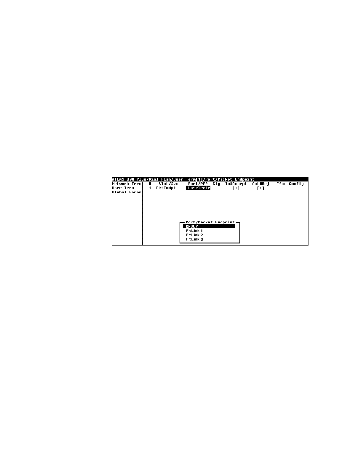
Chapter 5. Connecting Packet Endpoints
PKTENDPT
LOT/SVC
S
RT
P
To facilitate dial-up packet services, the ATLAS D
endpoints. These endpoints must be entered in the USER
menu. The P
UT#REJ
O
KTENDPT
,andI
menuincludesS
FCECONFIG
.
Write security: 3; Read security: 5
Selects the service. Select P
KTENDPT
/PEP Write security: 3; Read security: 5
Accepts the packet endpoint you wish to configure. Select from a specific
packet link that was configured with the P
G
ROUP
(see Figure 5-3). The G
ROUP
group. The interface configuration (I
ing on whether a specific packet link (endpoint) or the G
selected.
LOT/SVC
IALPLAN
ORT
, P
supports packet
ERM/PKTENDPT
T
/PEP, S
IG
N#ACCEPT
, I
.
ACKETMANAGER
menus or select
option allows you to define a hunt
FCECONFIG
) parameters vary, depend-
ROUP
option is
,
IG
S
N#ACCEPT
I
UT#REJ
O
FCECONFIG
I
Figure 5-3. Port/PEP Options in the Dial Plan
Write security: 3; Read security: 5
Not used for specific packet links (endpoints).
Write security: 3; Read security: 5
Configured as defined in the ATLAS 800
PLUS
User Manual.
Write security: 3; Read security: 5
Configured as defined in the ATLAS 800
PLUS
User Manual.
Write security: 3; Read security: 5
Figure 5-4 shows an example of the interface configuration for a normal
packet link. Figure 5-5 shows a similar configuration; however, in this
example, the selected packet link has been configured within the P
ANAGER
M
menus to include backup sublinks (see also, Primary | Backup
ACKET
Selection on page 4-17). Figure 5-6 shows the interface configuration when
the G
ROUP
option is selected.
5-2 ATLAS Frame Relay User Manual 61200263L1-1.1
Page 55

Chapter 5. Connecting Packet Endpoints
Figure 5-4. Packet Link Interface Configuration
Figure 5-5. Packet Link Interface Configuration with FR Backup Support
Figure 5-6. Packet Link GROUP Interface Configuration
UTDIALNUMBER
O
Write security: 3; Read security: 5
Defines the number dialed to originate a call.
UTGOINGCALLTYPE
O
Write security: 3; Read security: 5
Selects the terminating resource type, either D
EDIALTIMER
R
IGITAL
64K or D
IGITAL
56K.
Write security: 3; Read security: 5
Selects the time delay in seconds between redial attempts.
ANDOMIZETIMER
R
Write security: 3; Read security: 5
Enables/disables random delay added to the redial timer to avoid glare.
ETRYCOUNT
R
Write security: 3; Read security: 5
Defines the number of redials to attempt.
61200263L1-1.1 ATLAS Frame RelayUser Manual 5-3
Page 56

Chapter 5. Connecting Packet Endpoints
UTGOINGCALLER
O
Write security: 3; Read security: 5
Defines the presentation of the calling party number for this endpoint.
ID
OURCE
S
ID
Write security: 3; Read security: 5
Used to simplify the creation of a D
IALPLAN
in applications where the crite-
rion for switching calls to a certain endpoint is a function of which endpoint
originated the call. For further details, see the ATLAS 800
OUTEINCOMINGCALL
R
PLUS
User Manual.
Write security: 3; Read security: 5
Used to define the method which incoming calls are associated to the
packet endpoints. This item can have three options:
SINGINCOMINGNUM
U
Endpoint selection based on the incomingnumber.
SINGCALLINGPARTYNUM
U
Selection based on the Call ID as presented by the calling party. If this
option is selected, the C
ALLPARTYNUMBER
field is made available to
the interface configuration. This number allows you to configure the
calling part number used to select this packet endpoint.
U
SING
DBU H
ANDSHAKE
Selection based on a proprietary protocol. This option is only available
to packet endpoints with backup sublinks. DBU H
ANDSHAKE
is required
to interoperate with ADTRAN IQ and Express family products. It
enables the association of incoming calls with packet endpoints in cases
where there is a single call-in number (hunt group) and no Caller ID
information available.
UPPORT
S
DBU H
ANDSHAKE
Write security: 3; Read security: 5
This option is only available when the packet endpoint selected in the
P
ORT
/PEP field has backup sublinks. S
UPPORT
DBU H
ANDSHAKE
enables/
disables the generation and acceptance of ADTRAN frame relay handshake
upon connection. If the endpoint is configured to route incoming calls
based on the handshake information, this option is automatically enabled.
If another call routing method is in effect, however, this option can be
enabled to support the use of handshake information at the far end of the
link.
M
IN
DS0’
S
Write security: 3; Read security: 5
Set this to 1 for typical single-call connections. Setting this greater than 1
will restrict connections to endpoints supporting aggregation (e.g.,
BONDING) of the specified number of DS0s.
M
AX
DS0’
S
Write security: 3; Read security: 5
Set this to 1 for typical single-call connections. Setting this greater than 1
will accommodate connections to endpoints supporting aggregation (e.g.
BONDING) of up to the specified number of DS0s. This also sets the number of DS0s presented in the negotiation of outgoing aggregate calls.
5-4 ATLAS Frame Relay User Manual 61200263L1-1.1
Page 57

Chapter 5. Connecting Packet Endpoints
ALLROUTINGTABLE
C
Read security: 5
This tableisonlyvisible if G
ROUP
is selected in the P
RT
/PEPfield. The table
format changes, based on the selected routing option. See Figures 5-7
through 5-9. For each case, C
OURCE
S
ID,andMIN/MAXDS0
ALLPARAMS
S
, as described above.
contain O
UTDIAL
#, C
ALLER
Figure 5-7. Call Routing Table for Routing Using Incoming Number
ID,
Figure 5-8. Call Routing Table for Routing Using Call Party Number
Figure 5-9. Call Routing Table for Routing Using DBU Handshake
61200263L1-1.1 ATLAS Frame RelayUser Manual 5-5
Page 58

Chapter 5. Connecting Packet Endpoints
PKTVOICE
LOT/SVC
S
ATLAS provides the same level of capability for packet-switched voice as
originally provided for circuit-switched voice.
NTERFACECONFIGURATION
I
ERM
) sets configurationparameters for the endpoint. These parameters
T
(under D
IALPLAN>USERTERM
or N
ETWORK
vary by the type of port selected. Thefollowing section describes the configuration options available for packet-switched voice (see Figure 5-10). The
D
IALPLAN
The first step in configuring the D
ETWORKTERM
N
details on determining N
is only accessible when you are using the terminal mode.
or U
SERTERM
ETWORKTERM
IALPLAN
.RefertotheATLAS 800
for packet voice is to select
PLUS
User Manual for
SERTERM
or U
(see alsoNetworkTerm
on page 5-8 and User Term on page 5-8). Once this selection is made, a
number of fields become available. These fields are discussed in the
following sections.
Figure 5-10. Packet Switched Voice Options
Write Security: 3; Read Security: 5
Select PKT
OICE
V
as the service.
RT
P
/PEP Write Security: 3; Read Security: 5
Select the port/packet endpoint that you want to configure.
IG
S
N#ACCEPT
I
Not used for packet voice.
Write Security: 3; Read Security: 5
Configured as defined in the ATLAS 800
UT#REJ
O
Write Security: 3; Read Security: 5
Configured as defined in the ATLAS 800
FCECONFIG
I
Write Security: 3; Read Security: 5
Provides interface configuration parameters (see Figure 5-11).
PLUS
User Manual.
PLUS
User Manual.
Figure 5-11. Interface Configuration Panel
5-6 ATLAS Frame Relay User Manual 61200263L1-1.1
Page 59

Chapter 5. Connecting Packet Endpoints
DLCI
Write Security: 3; Read Security: 5
Selects the appropriate DLCI for this dial plan entry.
OICEPORT
V
Write Security: 3; Read Security: 5
Identifies the voice port address of the remote unit. FSU 5622s support
ports 1 and 2. A remote ATLAS supports ports 1 through 255.
ONFLICTREPORT
C
Read Security: 5
Provides a description of a conflict if it exists. Potential problems include
DLCI unavailable or Voice port already in u se.
OICECOMPRESSION
V
Write Security: 3; Read Security: 5
Selects the voice compressionalgorithm used by this endpoint. Older
ADTRAN 5622 FRADs use CCITT G.723.1compression at 6.3 kbps. Newer
FRADs also support the proprietary NETCODER algorithm at 6.4 kbps.
Both endpoints must agree about the compression algorithm choice.
ILENCESUPPRESSION
S
Write Security: 3; Read Security: 5
Reduces the total system bandwidth load by preventing ATLAS from sending frames containing a special silence code during periods of silence. Both
endpoints must agree to use silence suppression. By default, silence suppression is D
decrease the total system bandwidth, ENABLE
ISABLED
. To prohibit silence frames from transmitting and to
this feature.
ALLER
C
OURCE
S
IGNALINGMETHOD
S
Write Security: 3; Read Security: 5
Selects the type of signaling that the remote port is configured to expect.
Available options include the following: E&M I
OOPSTART
L
IRECTINWARDDIALING
D
.
Write Security: 3; Read Security: 5
Defines whether or not Direct Inward Dialing (DID) is used by the remote
equipment. If DID is enabled,then the following options must be configured for N
ETWORK
and U
SERTERM
ID Write Security: 3; Read Security: 5
Defines the number ATLAS uses to provide caller ID to the network for outgoing calls sent through this endpoint.Thisfield only displays if D
NWARDDIALING
I
is set to D
ISABLED
menu item is optional.
ID Write Security: 3; Read Security: 5
Defines the source ID. This field only displays if D
set to DISABLED
,andU
SERTERM
optional.
MMEDIATE
, E&M W
INK
configurations.
IRECT
,andU
SERTERM
is selected. Setting this
IRECTINWARDDIALING
is selected. Setting this menu item is
,and
is
61200263L1-1.1 ATLAS Frame RelayUser Manual 5-7
Page 60

Chapter 5. Connecting Packet Endpoints
NETWORK TERM
DID D
RANSFERRED
T
DID P
RUNKNUMBER
T
USER TERM
DID D
RANSFERRED
T
IGITS
REFIX
IGITS
Write Security: 3; Read Security: 5
Defines the number of digits sent to ATLAS from the Network if D
NWARDDIALING
I
(see page 5-7) is enabled.
IRECT
Write Security: 3; Read Security: 5
Defines to ATLAS the prefix digits which are not receivedas a part of the
DID number. ATLASuses the combination of prefix and DID number to
determine the user endpoint that should receive the incoming call.
Write Security: 3; Read Security: 5
Determines which user endpoint should receive the incoming call when the
network connection does not provide DID digits. This field only displays if
D
IRECTINWARDDIALING
ERM
(see page 5-8) is selected.
T
(see page 5-7) is set to Disabled, and N
ETWORK
Write Security: 3; Read Security: 5
Defines the number of digits ATLAS is to send to the user equi pment. This
field only displays if D
IRECTINWARDDIALING
(see page 5-7) is set to
Enabled.
ALLER
C
UMBER
N
OURCE
S
ID
Write Security: 3; Read Security: 5
Defines the number ATLAS uses to provide caller ID to the network for outgoing calls sent through this endpoint.This field only displays if D
NWARDDIALING
I
(see page 5-7) is set to D
selected. Setting this menu item is optional.
ID Write Security: 3; Read Security: 5
Defines the source ID. This field only displays if D
(see page 5-7) is set to D
ISABLED
menu item is optional.
,andU
ISABLED
SERTERM
IRECT
,andU
SERTERM
IRECTINWARDDIALING
is
is selected. Setting this
5-8 ATLAS Frame Relay User Manual 61200263L1-1.1
Page 61

Chapter 6
Frame Relay Configuration
Examples
This chapter provides several step-by-step examples to help you configure
your ATLAS for frame relay. Figure 6-1 illustrates an ATLAS configured to
support packet data.
Router
SNA Router
Nx
Port
Nx
Port
Pkt
Endpoint 2
Pkt
Endpoint 3
IP
Endpoint 1
SNA
Pkt
ATLAS
T1
Port
FrameRelay
Network
Figure 6-1. ATLAS to Support Packet Data Configuration
The general procedure for configuring the ATLAS depicted in Figure 6-1 is
as follows:
1. From P
ACKETMANAGER/PACKETENDPNTS/CONFIG
,createthreepacket
endpoints.
2. From P
ACKETMANAGER/PACKETCNCTS
, make the IP and SNA protocol
connections.
3. From D
EDICATEDMAP
, connect the packet endpoints to the physical
ports.
61200263L1-1.1 ATLAS Frame Relay User Manual 6-1
Page 62

Chapter 6. Frame Relay Configuration Examples
EXAMPLE 1: IP ROUTING NETWORK—ATLAS AS THE
CENTRAL-SITE ROUTER
Example 1 (see Figure 6-2) depicts a typical IP routing network using an
ATLAS as the central-site router. (This ATLAS unit is the ATLAS 800
with a frame relayupgrade.) A TSU 100e with a router module is located at
each of the two remote sites, and an FSU with an external router is located at
a third site. The central-site ATLAS terminates a full T1 frame relay
connection from the XYZ service provider, and the internal router
terminates the IP traffic. To re-create this example, follow the process
discussed below.
PLUS
Atlanta
ATLAS800
with frame relayupgrade
Figure 6-2. IP Routing Network with ATLAS as the Central-Site Router
Step 1 From P
point(seeFigure6-3).
Chicago
F-T1
PLUS
T1
XYZ Public
FrameRelay
NewY ork
F-T1
L
A
N
ACKETMANAGER/PACKETENDPOINTS/CONFIG
Boston
DDS
L
A
N
TSU 100e
with router module
L
A
N
TSU 100e
with router module
Router
FSU
, create the packet end-
Figure 6-3. Menu for Creating Packet Endpoints
Step 2 From P
ACKETMANAGER/PACKETENDPOINTS/CONFIG/SUBLINKS
,createthree
sublinks or DLCIs for frame relay (see Figure 6-4).
Figure 6-4. Menu for Creating Sublinks or DLCIs
6-2 ATLAS Frame Relay User Manual 61200263L1-1.1
Page 63

Chapter 6. Frame Relay Configuration Examples
Step 3 From P
router (see Figure 6-5).
Step 4 From D
endpoint to the appropriate physical interface (see Figure 6-6).
Figure 6-6. Menu for Attaching Packet Endpoint to Physical Interface
ACKETMANAGER/PACKETCNCTS
, connect the IP traffic to the internal
Figure 6-5. Menu for Connecting IP Traffic to Internal Router
EDICATEDMAPS/CREATE/EDITMAPS/CONNECTS
, attach the packet
61200263L1-1.1 ATLAS Frame RelayUser Manual 6-3
Page 64

Chapter 6. Frame Relay Configuration Examples
EXAMPLE 2: IP ROUTING NETWORK—EXTERNAL ROUTERS
Example 2 (see Figure 6-7) depicts an IP network with external routers. An
PLUS
ATLAS 800
TSU 100e with an external router connected to an Nx56/64 module is l ocated at each of tworemote sites, and an FSUwith an external router is located
at the third remote site. At the central site, ATLAS terminates a full T1frame
relay connection from the XYZ service provider and switches the PVCs to
the external router. To re-create this example, follow the process discussed
below.
with a frame relay upgrade is located at the central site. A
Chicago
F-T1
Router
Atlanta
ATLAS800
with frame rela yupgrade
Step 1 From P
points (see Figure 6-8).
PLUS
Server
T1
XYZ Public
FrameRelay
F-T1
Boston
DDS
Figure 6 -7. IP Network With External Routers
ACKETMANAGER/PACKET ENDPOINTS/CONFIG
TSU 100e
NewY ork
Router
TSU 100e
Router
FSU
, create the packet end-
Figure 6-8. Menu for Creating the Packet Endpoints
Step 2 From P
ACKETMANAGER/PACKETENDPOINTS/CONFIG/SUBLINKS
,configure
the sublinks for both packet endpoints. For simplicity, use the same DLCI
number going to the serveras going to the frame relay network (see Figures
6-9 and 6-10).
6-4 ATLAS Frame Relay User Manual 61200263L1-1.1
Page 65
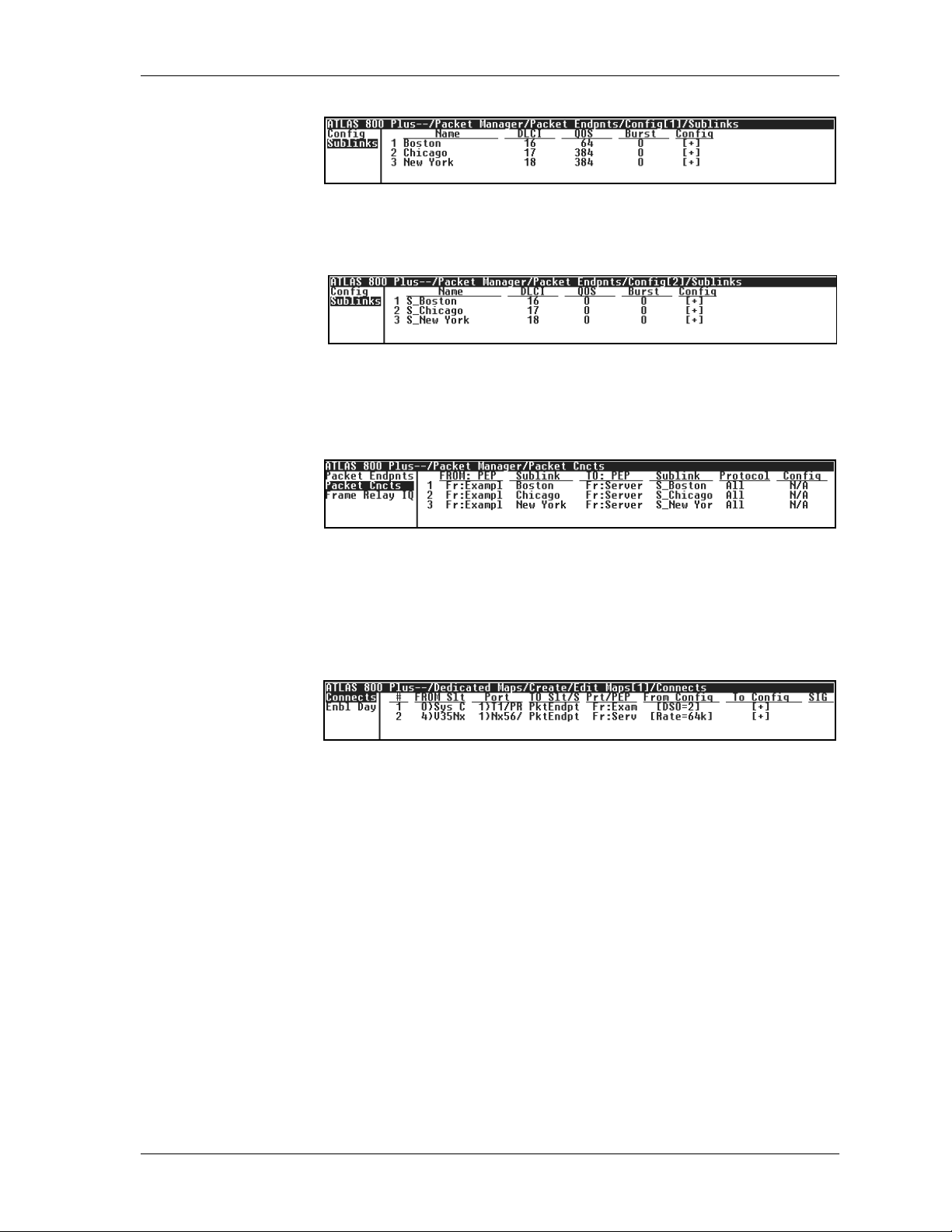
Chapter 6. Frame Relay Configuration Examples
Figure 6-9. Menu for Configuring Packet Endpoints (1) Sublinks
Figure 6-10. Menu for Configuring Packet Endpoints (2) Sublinks
Step 3 Make the packet connections(see Figure 6-11).
Figure 6-11. Menu for Making the Packet Connections
Step 4 Connect the packetendpoints to thephysicalport. The server connectsto an
Nx56/64 module, and the frame relay network connects to a T1 port on the
controller (see Figure 6-12).
Figure 6-12. Menu for Connecting Packet Endpoints to Physical Port
61200263L1-1.1 ATLAS Frame RelayUser Manual 6-5
Page 66

Chapter 6. Frame Relay Configuration Examples
EXAMPLE 3: PRIVATE FRAME RELAY NETWORK—ATLAS
CENTRAL-SITE ROUTER
Example 3 (see Figure 6-13) depicts a private frame relay network using
ATLAS asthecentral-siterouter and a frame relay switch.(ThisATLASunit
istheATLAS800
module is located at each of three remote sites. At the central site, ATLAS
terminates a full T1 with eight DS0s from each of the remote sites DACSed
onto the single T1. (See, also, the discussion of DACSing in the ATLAS User
Manual.) To re-create this example, follow the process discussed below.
PLUS
with aframerelayupgrade.) A TSU 100ewitharouter
Atlanta
ATLAS800
with frame relayupgrade
Figure 6-13. Private Frame Relay Network—ATLAS Central-SiteRouter
Step 1 From P
points (see Figure 6-14).
Chicago
F-T1
(8 DS0)
PLUS
T1
Data from
L
A
three sites
groomed
onto oneT1
DACS
N
F-T1
(8 DS0)
ACKETMANAGER/PACKETENDPOINTS/CONFIG
NewY ork
F-T1
(8 DS0)
Boston
L
A
N
TSU 100e
with router module
L
A
N
TSU 100e
with router module
L
A
N
TSU 100e
with router module
, create the packet end-
Figure 6-14. Menu for Creating Packet Endpoints
Step 2 From P
ACKETMANAGER/PACKETENDPOINTS/CONFIG/SUBLINKS
,createthree
identical sublinks. (Only one sublink is shown in Figure 6-15).
Figure 6-15. Menu for Creating Sublinks
6-6 ATLAS Frame Relay User Manual 61200263L1-1.1
Page 67

Chapter 6. Frame Relay Configuration Examples
Step 3 From P
ACKETMANAGER/PACKETCNCTS
, connect the packet endpoints (see
Figure 6-16).
Figure 6-16. Menu for Connecting Packet Endpoints
Step 4 Connect the packet endpoint to the physical interface (see Figure 6-17).
Figure 6-17. Menu for Connecting Packet Endpoint to Physical Interface
61200263L1-1.1 ATLAS Frame RelayUser Manual 6-7
Page 68
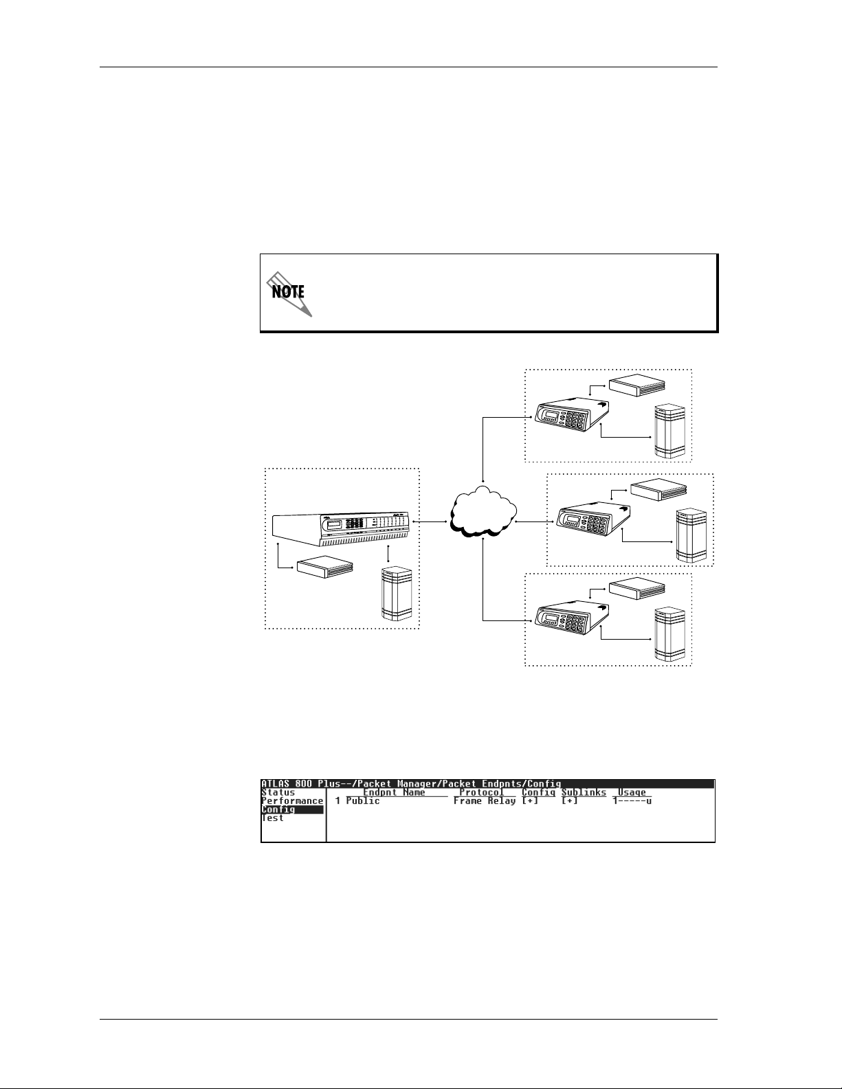
Chapter 6. Frame Relay Configuration Examples
EXAMPLE 4: PUBLICFRAME RELAYNETWORK—IPDATA AND
PACKET V OICE
Example 4 (see Figure 6-18) depicts a public frame relay network with IP
data and packet voice. An ATLAS 800
installed is located at the central site, and an Express 5200 is located at each
remote site. ATLAS acts as the central-site router and performs voice
switching. To re-create this example, follow the process discussed below.
PLUS
with the frame relay upgrade
Atlanta
Packet voice termination requires the P
ATLAS 800
Router
PLUS
PBX
T1
XYZ Public
FrameRelay
Figure 6-18. Public Frame Relay Network
DDS
DDS
ACKETVOICEMODULE
Boston
Express 5200
Chicago
DDS
Express 5200
NewY ork
Express 5200
.
Router
PBX
Router
PBX
Router
PBX
Step 1 From P
ACKETMANAGER/PACKETENDPNTS/CONFIG
,createthepacketend-
point(seeFigure6-19).
Figure 6-19. Menu for Creating Packet Endpoint
Step 2 From P
ACKETMANAGER/PACKETENDPNTS/CONFIG
,configurethesublinks
(see Figure 6-20).
6-8 ATLAS Frame Relay User Manual 61200263L1-1.1
Page 69

Chapter 6. Frame Relay Configuration Examples
Figure 6-20. Menu for Configuring Sublinks
Step 3 From P
ACKETMANAGER/PACKETCNCTS
, connect the packetdata to the inter-
nalrouter(seeFigure6-21).
Figure 6-21. Menu for Connecting Packet Data
Step 4 Configure the dial plan for packet voice. Refer to ATLAS User Manual for de-
tail on dial plan configuration (see Figure 6-22).
Figure 6-22. Menu for Configuring Dial Plan
Step 5 Connect the packet endpoint to the physical interface (see Figure 6-23).
Figure 6-23. Menu for Connecting Packet Endpoints
61200263L1-1.1 ATLAS Frame RelayUser Manual 6-9
Page 70

Chapter 6. Frame Relay Configuration Examples
EXAMPLE 5: P RIVATE FRAME RELAY NETWORK—PACKET
VOICE
Example 5 (see Figure 6-24) shows a private frame relay network using
compressed voice in a private frame relay network. An ATLAS 800
with the frame relay upgrade is located at each site and a PBX is connected
to the ATLAS using a clear-channel T1 connection. Each PBX uses DS0s 1—
23 for voice and DS0 24 for signaling; all calls are to be completely managed
by the PBXs. In this network, ATLAS does not terminate the signaling
information, but forwards the signaling between endpoints using a
transparentbit oriented protocol (TBOP) frame relay connection. To recreate this example, follow the process discussed below.
Packet voice transmission requires the Voice Compression Module.
PLUS
Atlanta
Router
Figure 6-24. Private Frame Relay Network Using Compressed Voice
Step 1 From P
points:createaframerelayendpointfortheprivateframerelaylink,and
createaTBOPlinktocarrythesignalingbetweenthePBXs(seeFigure6-25).
Step 2 From P
the sublinks.
ATLAS800
PLUS
Private
Boston
ATLAS800
FrameRelay
Network
Router
PBX
ACKETMANAGER/PACKETENDPNTS/CONFIG
Figure 6-25. Menu for Creating Packet Endpoints
ACKETMANAGER/PACKETENDPOINTS/CONFIG/SUBLINKS
,createthepacketend-
PLUS
PBX
,configure
All 23 voice channels can be carried by one DLCI transported on five DS0
channels. One DS0 and one DLCI are required for the TBOP channel carrying the signaling between the PBXs. To ensure that both the voice and the
TBOP DLCIs are allocated their necessary frame relay bandwidth, set the
Quality-Of-Service (QOS) parameter with 64K allocated to the TBOP channel and 320K(5*64) allocated to t he voice channels (see Figure 6-26).
6-10 ATLAS Frame Relay User Manual 61200263L1-1.1
Page 71
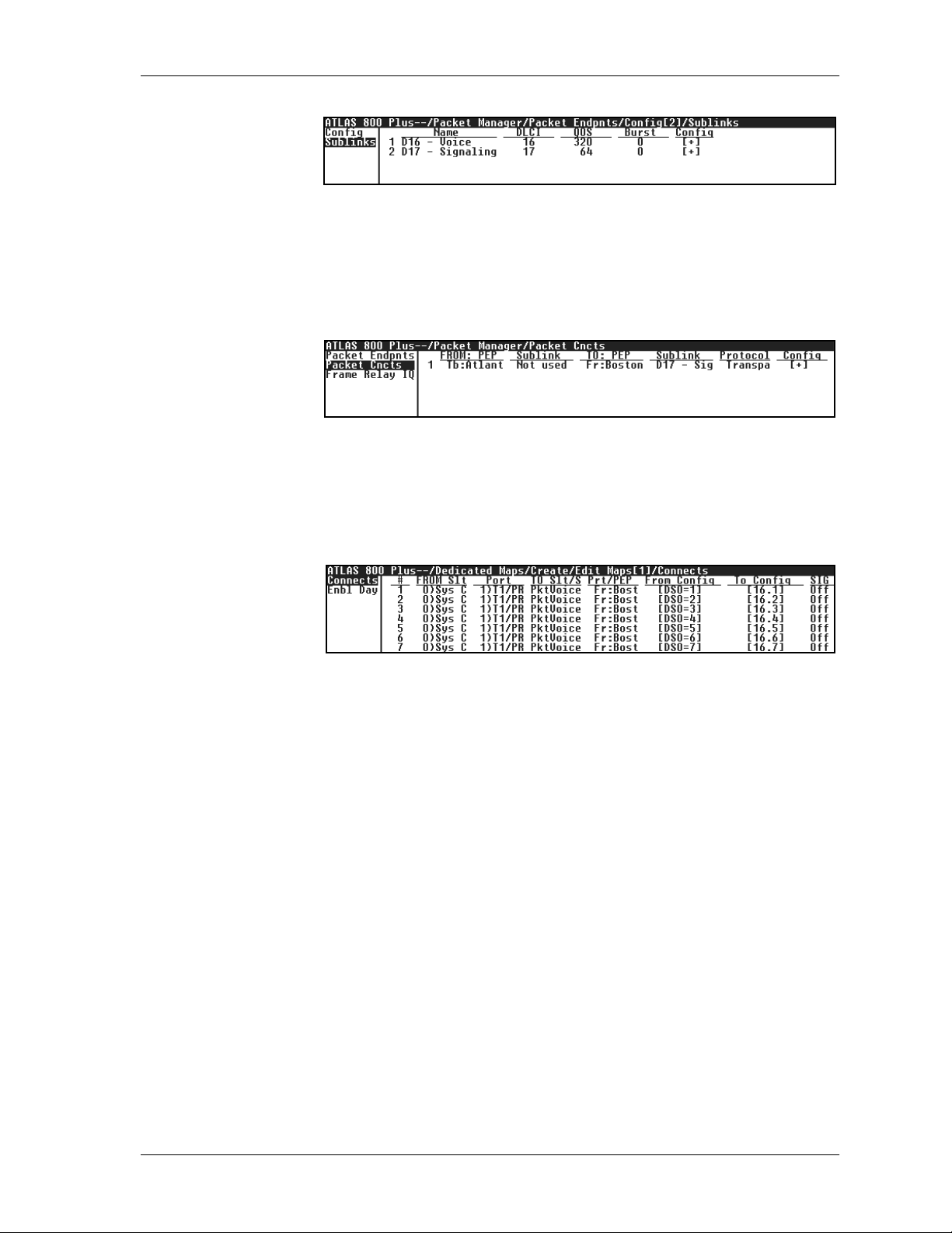
Chapter 6. Frame Relay Configuration Examples
Figure 6-26. Menu for Configuring Sublinks
Step 3 Connect the TBOP packet endpoints. Connect the TBOP data path between
the DS0 containing the signaling information and the private frame relay resource (see Figure 6-27).
Figure 6-27. Menu for Connecting the TBOP Endpoints
Step 4 Connect packet endpoints to the physical links. Each DS0 carrying voice
from the PBX must be connected to the frame relay endpoint (see Figure 6-
28).
Figure 6-28. Menu for Connecting Packet Endpoints to Physical Links
61200263L1-1.1 ATLAS Frame RelayUser Manual 6-11
Page 72
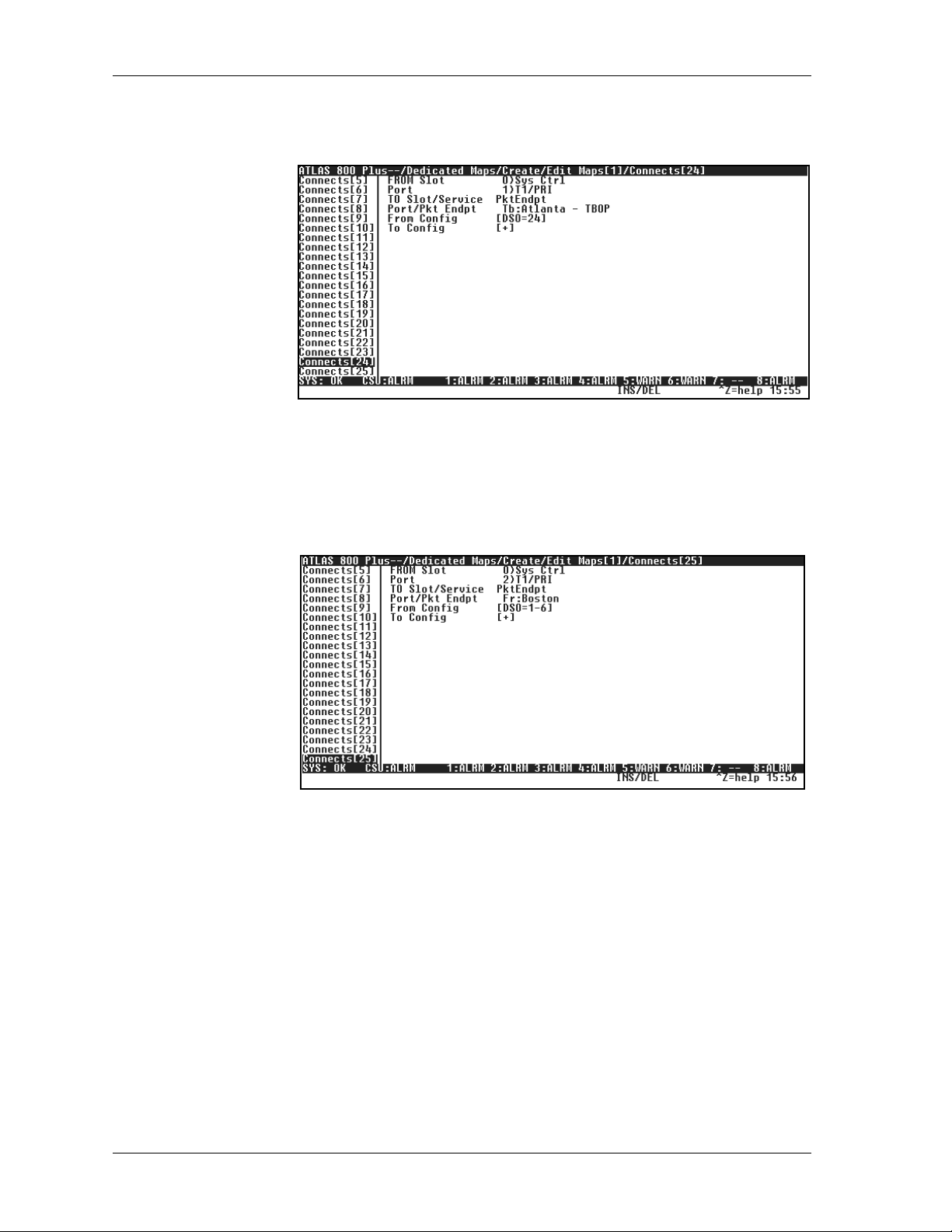
Chapter 6. Frame Relay Configuration Examples
Step 4-a TBOP Connection Details. The PBX DS0 carrying the signaling information
must be connected to th e frame relay endpoint (see Figure 6-29).
Figure 6-29. Connecting PBX DS0 to Frame Relay Endpoint
Step 4-b Frame Relay Connection Details. Connecting the frame relay endpoint to the
private frame relay network requires sixDS0s, one for the TBOP connection
andfiveforthecompressedvoiceconnections(seeFigure6-30).
Figure 6-30. Connecting FR Endpoint to FR Private Network
6-12 ATLAS Frame Relay User Manual 61200263L1-1.1
Page 73
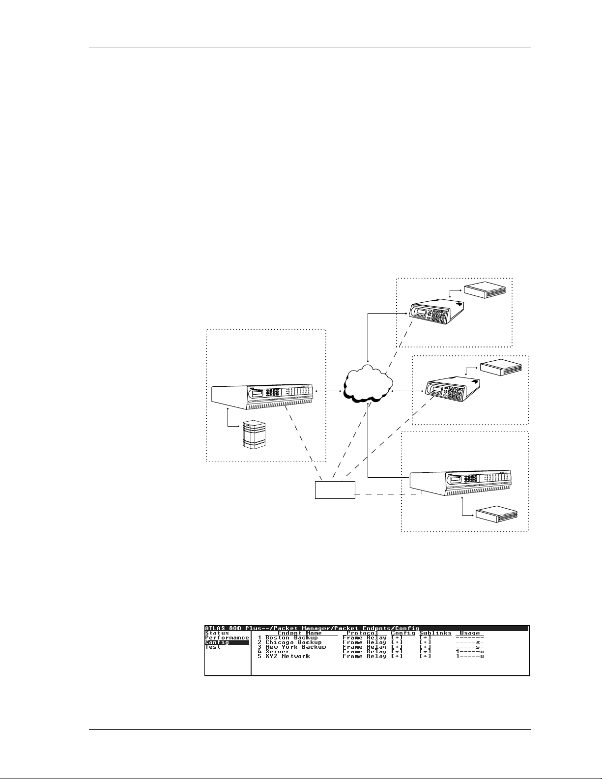
Chapter 6. Frame Relay Configuration Examples
EXAMPLE 6: IP ROUTING NETWORK WITH DIAL BACKUP
Example 6 depicts an IP network with external routers (seeFigure 6-31). An
ATLAS800
and at one of the remote sites (Boston). A TSU IQ with an external router
connected to an Nx56/64 module is located at each of the two remaining remote sites (Chicago and New York). At the central site, ATLAS terminates a
full T1 frame relay connection from the XYZ service provider and switches
the PVCs (sublinks) to the external router.
In the event of problems in the connections to the XYZ public frame relay
provider, each device can redirect traffic to a backup network. In this
example,eachTSUIQ uses an ISDN DBU moduletoconnecttothe PSTN via
BRI. Each ATLAS is connected to the PSTN via PRI. To re-create this
example, follow the process discussed below to configure the central site
ATLAS.
PLUS
with a frame relay upgrade islocatedatboththecentralsite
Chicago
F-T1
Router
Atlanta
ATLAS800
with frame relayupgrade
Dashed lines indicate
backup lines.
Step 1 From P
points (see Figure 6-32).
PLUS
Server
PRI
T1
BRI
ISDN
XYZ Public
FrameRelay
BRI
PRI
F-T1
Boston
F-T1
Figure 6-31. IP Routing Network with Dial Backup
ACKETMANAGER/PACKETENDPNTS/CONFIG
TSU IQ
NewY ork
Router
TSU IQ
ATLAS800
PLUS
with frame relayupgrade
Router
, create the packet end-
Figure 6-32. Menu for Creating the Packet Endpoints
61200263L1-1.1 ATLAS Frame RelayUser Manual 6-13
Page 74

Chapter 6. Frame Relay Configuration Examples
Step 2 Configure thesublinksforthepacketendpoints.Forsimplicity,usethesame
DLCI number going tothe server as going to the frame relay network (see
Figures 6-33 through 6-37).
Figure 6-33. Menu forConfiguring Packet Endpoint 1 (Server)Sublinks
Figure 6-34. Menu for Configuring Packet Endpoint 2
(XYZ Network) Sublinks
Figure 6-35. Menu for Configuring Packet Endpoint 3
(Chicago Backup) Sublink
Figure 6-36. Menu for Configuring Packet Endpoint 4
(New York Backup) Sublink
Figure 6-37. Menu for Configuring Packet Endpoint 5
(Boston Backup) Sublink
6-14 ATLAS Frame Relay User Manual 61200263L1-1.1
Page 75

Chapter 6. Frame Relay Configuration Examples
Step 3 Configure the backup sublinks for use as backup, and tie them to the prima-
ry sublinks. See Figure 6-38 for the sublink configuration for the Boston
backup sublink. Follow similar steps to configure the Chicago and New
York sublinks.
Figure 6-38. Menu for Configuring Backup Sublink 1
Step 4 Make the packet connections(see Figure 6-39).
Figure 6-39. Menu for Making the Packet Connections
Step 5 Connect the packetendpoints to thephysicalport. The server connectsto an
Nx56/64 module, and the frame relay network connects to a T1 port on the
controller (see Figure 6-40).
Figure 6-40. Menu for Connecting Packet Endpoints to Physical Port
Step 6 Add the backup endpoints to the dial plan, asshown below (see also Figure
6-41). Refer to the ATLAS manual for details on dial plan configuration.
Backup Sublink OutDial
Accept #
Number
Chicago Backup (454) 111-9999 (444) 963-1111
New York Backup (545) 222-8888 (444) 963-2222
Boston Backup (555) 333-7777 (444) 963-3333
61200263L1-1.1 ATLAS Frame RelayUser Manual 6-15
Page 76

Chapter 6. Frame Relay Configuration Examples
Figure 6-41. Menu for Adding Backup Packet Endpoints to the Dial
Plan
Step 7 Configure the interface options for the Boston endpoint under the I
ONFIG
C
menu (see Figure 6-42). Follow similar steps to configure the New
York and Chicago endpoints, using dial numbers of (5 45) 222-8888 and
(454) 111-9999, respectively.
The ADTRAN IQ and Express families of products require that
the S
UPPORT
DBU H
ANDSHAKE
option be set to YESfor proper
operation.
For those products that allow enabling or disabling of this option,
the devices at each end of the connection must be set the same for
proper operation.
In this example, this option is set to N
connection, but set to Y
ES
for the Atlanta-to-Chicago and
O
for the Atlanta-to-Boston
Atlanta-to-New York connections.
FCE
Figure 6-42. Menu for Configuring the Switched Packet Endpoint
Interface Configuration
Step 8 Configure the PRI under the N
ETWORKTERM
list of the dial plan (see Figure
6-43). Add three entries to the outgoing accept number list: (454 )111-9999,
(545) 222-8888, and (555) 333-7777.
Figure 6 -43. Menu for Configuring the PRI Connections to the PSTN
6-16 ATLAS Frame Relay User Manual 61200263L1-1.1
Page 77

Chapter 6. Frame Relay Configuration Examples
EXAMPLE 7: PRIVATE FRAME RELAY NETWORK WITH
DEDICATED BACKUP
Example 7 depicts a private frame relay network connecting two sites (see
PLUS
Figure 6-44). An ATLAS 800
site. A full T1 private frame relay connection exists for routing compressed
voice traffic. Another full T1 private frame relay connection exists between
the two sites to route IP traffic (data and compressed voice). Each ATLAS
must include a Voice Compression and T1/PRI module to support these requirements.
In the event of a problemon the T1 circuit dedicated for voice traffic, the second T1 can be used to reroute the voice traffic, sharing bandwidth with the
IP traffic. To re-create this example, follow the process discussed below to
configure the ATLAS in Atlanta. The ATLAS in Boston requires a similar
configuration.
with a frame relay upgrade exists at each
Atlanta
Boston
CompressedV oice
ATLAS 800
with frame relay upgrade
PBX
PLUS
L
A
N
T1
T1
Only
Private
FrameRela y
Network
Data
&
CompressedV oice
Backup
ATLAS 800
with frame relay upgrade
T1
T1
L
A
N
PLUS
PBX
Figure 6-44. Private Frame Relay Network with Dedicated Backup
Step 1 Create the packet endpoints,twoframerelayendpoints for the private frame
relay links, and one TBOP link for carrying the signaling between the PBXs.
Select the signaling role of B
OTH
for the link used for backup (see Figure 6-
45).
Figure 6-45. Menu for Creating Packet Endpoints
Step 2 Configure the sublinks for the voice link.
All 23 voice channels can be carried by one sublink transported on five DS0
channels to Boston. One DS0 channel and one sublink are required for the
TBOP channel carrying the signaling between the PBXs.Toensurethatboth
the voice and the TBOP sublinks are allocated their necessary frame relay
bandwidth, set the Quality-Of-Service (QOS) parameter with 64k allocated
to the TBOP channel and 320k (5*64)allocated to the voice channels. The re-
61200263L1-1.1 ATLAS Frame RelayUser Manual 6-17
Page 78

Chapter 6. Frame Relay Configuration Examples
maining bandwidth is reserved for backing up the data link (see
Figure 6-46).
Step 3 Configure the sublinks for the data/backup link (see Figure 6-47).
Figure 6-46. Menu for Configuring Sublinks
Figure 6-47. Menu for Configuring Sublinks
Step 4 Configure the backup sublinks for use as backup, and tie them to the prima-
ry sublinks (see Figures 6-48 and 6-49).
Figure 6-48. Menu for Configuring Backup Voice Sublink
Figure 6-49. Menu for Configuring Backup Signaling Sublink
6-18 ATLAS Frame Relay User Manual 61200263L1-1.1
Page 79

Chapter 6. Frame Relay Configuration Examples
Step 5 Make the packet connections(see Figure 6-50).
Figure 6-50. Menu for Making the Packet Connections
Step 6 Connectthepacketendpointstothephysicalports.
Each DS0 carrying voice fromthe PBX must be connectedto the frame relay
endpoint. Figure 6-51 shows the entries for channels 1-21. The P
is the B
OSTON_VOICE
packet endpoint.
RT
/PEP field
Figure 6-51. Menu for Connecting Packet Endpoints to Physical Ports
Step 6-a The TBOPendpoint is mapped to DS0 24 of the PBX connection.All 24 DS0s
of controller T1 port 2 are mapped to the private frame relay link to Boston.
Only 6 DS0s are required for the voice and signaling channels. The remaining 18 channels are available for backing up the data link. The data link,
Boston_Data, is mapped toaT1portonaT1/PRImodule.Figure 6-52 shows
the remaining dedicated map entries.
Figure 6-52. Menu for Connecting Packet Endpoints to Physical Ports
61200263L1-1.1 ATLAS Frame RelayUser Manual 6-19
Page 80

Chapter 6. Frame Relay Configuration Examples
EXAMPLE 8: IP ROUTING USING PPP
Example 8 depicts a typical IP routing situation for a point-to-point link using PPP(seeFigure6-53). A TSU 100e with a RouterModuleis at the remote
site.TheATLASterminatesuptoa full T1 connection tothepeer.To recreate
this example, follow the process discussed below.
Figure 6-53. Private Frame Relay Network with Dedicated Backup
Step 1 From P
point (see Figure 6-54).
ATLAS 800
PLUS
with frame relayupgrade
T1
TSU 100e with
Server
ACKETMANAGER/PACKETENDPOINTS/CONFIG
router module
Figure 6-54. Menu for Creating Packet Endpoints
, create the packet end-
Step 2 From P
TION
, configure the authentication parameters for the peer (Rx) and the au-
ACKETMANAGER/PACKETENDPOINTS/CONFIG/CONFIG/AUTHENTICA
-
thentication parameters the peer is going to use to authenticate you (Tx) (see
Figure 6-55).
Figure 6-55. Menu for Configuring Sublinks
6-20 ATLAS Frame Relay User Manual 61200263L1-1.1
Page 81

Chapter 6. Frame Relay Configuration Examples
Step 3 From P
Router using t he IP protocol (see Figure 6-56).
Step 4 From R
the peer. For unnumbered links, you should leave the Address field as
0.0.0.0andtheFar-EndAddresscanbethe peer’s address(thisisnotneeded
since PPP will negotiate the peer’s IP address) (see Figure 6-57).
ACKETMANAGER/PACKETCNCTS
Figure 6-56. Menu for Configuring Sublinks
OUTER
NTERFACES
/IP/I
, configure the IP addresses for the ATLAS and
, connect the packet endpoint to the
Figure 6-57. Menu for Configuring Backup Voice Sublink
Step 5 From D
EDICATEDMAPS/CREATE/EDITMAPS
[1]/C
et endpoint to a physical port (see Figure 6-58).
Figure 6-58. Menu for Making the Packet Connections
Step 6 The state of the PPP link canbeviewed from P
POINTS/PERFORMANCE
[1]/L
INKSTATS
. These stats indicate the state of the dif-
ferent layers of PPP.
ONNECTS
ACKETMANAGER/PACKETEND
, connect the pack-
-
Figure 6-59. Menu for Connecting Packet Endpoints to Physical Ports
61200263L1-1.1 ATLAS Frame RelayUser Manual 6-21
Page 82

Chapter 6. Frame Relay Configuration Examples
6-22 ATLAS Frame Relay User Manual 61200263L1-1.1
Page 83

Chapter 7
Using Frame Relay IQ
RAMERELAY
F
information for ports and PVCs is collected inday and interval (5, 10, 15, 20,
or 30 minutes) statistics tables. Users can adjust the number of days and
number of intervals for which statistics are gathered; however, interval collections are limited to 5, 10, 15, 20, or 30 minutes.
IQ provides information about frame relay activity. Statistical
F
RAMERELAY
Packet Manager Packet Cncts
IQ
ENABLE IQ STATS
Gathers and stores statistical information in the submenus E
S
TATS
ORTENABLES
, P
, C
ONFIG
,andV
IEW
IQ S
TATISTICS
NABLE
(see the menu tree
in Figure 7-1)
Packet Endpnts
Cncts Sort Enable IQ Stats Name
Frame Relay IQ
Port Enables Enable Port All PVCs Enabled
All Sublinks Name
Sublinks DLCI
Enable
Current PIVs
Config Interval Period
View IQ Statistics Max Days
Max Intervals
Figure 7-1. Frame Relay IQ Menus
Globally enables and disables IQ statistics gathering. IQ statistics are only
gathered when this option is enabled. This field defaults to the original setting of [15
MIN,7DAYS
,96
INTS
] when re-enabled.
IQ
PORT ENABLES
Enables and disables IQ statistics gathering for each port. Use the submenus
AME
NABLE
, E
N
LLSUBLINKS
, A
,andS
UBLINKS
to configure the individual
ports.
AME
N
61200263L1-1.1 ATLAS Frame Relay User Manual 7-1
Displays the port number and name.
Page 84

Chapter 7. Using Frame Relay IQ
NABLEPORT
E
LLSUBLINKS
A
UBLINKS
S
Enables and disables IQ statistics gathering for the port identified in N
AME
Provides an easy way to enable or disable IQ statistics gathering on all sublinks. When this activator reads D
tics gathering on all sublinks. Whenit readsE
ISABLE
,pressing
NABLE
disables IQ statistis-
Enter
,pressing
Enter
enables
IQ statistics gatering on all sublinks.
Identifies the PVC to be polled.
A
LL
PVCSE
NABLED
Indicates the number of sublinks that ATLAS will collect IQ data for within
the given link.
AME
N
Displays the user-designated name of the sublink (up to 15 characters).
DLCI
Displays the Data Link Connection Identifier (circuit number).
NABLE
E
Indicates collection of IQ data for the target DLCI.
.
CONFIG
URRENT
C
NTERVAL
I
ERIOD
P
AXDAYS
M
AXINTERVALS
M
PIV
Sets the parameters for IQ statistics g athering.
S
Identifies resources used by IQ statistics storage. A PIV is a port or PVC per
interval. ATLAS can track up to 10,000 PIVs. Think of it as a resourcemeter.
The PIV number is derived from the M
AXDAYS
and M
AXINTERVALS
bytheuser.Changingoneaffectstheother.
Sets the period for IQ statistics gathering. Options are 5, 10, 15, 20, and 30
minutes.
Defines the number of history day intervals to keep. Maximum entry is dependent on the M
AXINTERVALS
setting.
Defines the number of history intervals to keep. Maximum entry is dependent on the M
AXDAYS
setting.
selected
7-2 ATLAS Frame Relay User Manual 61200263L1-1.1
Page 85
Chapter 7. Using Frame Relay IQ
VIEW IQ STATISTICS
Displays statistical information gathered for intervals and days on a port
and for intervalsand days on sublinks (PVCs or DLCIs). Figure 7-2 shows
the menu tree for this option.
Rx Frames Rx Frames
Rx Bytes Rx Bytes
MaxRxThru MaxRxThru
Avg Rx Thru Avg Rx Thru
MaxRxUtil% MaxRxUtil%
Avg Rx Util% Avg Rx Util%
Tx Frames Tx Frames
Tx Bytes Tx Bytes
MaxTxThru MaxTxThru
Avg Rx Thru Avg Rx Thru
MaxTxUtil% Max Tx Util%
Avg Tx Util% Avg Tx Util%
Port UA Time PVC IA Time
Interval/Day Sig Down T ime Rx FECN
PacketEndpnts Signal Error Tx FECN
Packet Manager Packet Cncts Enable IQ Stats Signal T/O Rx BECN
Cncts Sort Port Enables Sig State Chg Tx BECN
Frame Relay IQ
Config Rx Full Stat Rx DE
View IQ Statistics
Sublink Avg Tx Frame
Tx Full Stat Tx DE
Rx LI only Rx CR
Tx LI only Tx CR
Async Status Lost Frames
Discard Frame Rmt Lost Frms
Aborts Rx Burst Sec
CRC Error Tx Burst Sec
Octet Align Min Rx Frame
Length Error Max Rx Frame
EA Violation Avg Rx Frame
Inactive DLCI Min Tx Frame
Invalid DLCI Max Tx Frame
Min Frame Dly
Max Frame Dly
Avg Frame Dly
PVC State Change
Figure 7-2. View IQ Statistics Menu Tree
NTERVAL/DAY
I
INK
(L
)
Descriptions of the statistics available in the I
low:
XFRAMES
R
NTERVAL
or DAYsubmenus fol-
The number of frames the port received for the interval or day.
XBYTES
R
Thenumberofbytestheportreceivedfortheintervalorday.
61200263L1-1.1 ATLAS Frame RelayUser Manual 7-3
Page 86

Chapter 7. Using Frame Relay IQ
MAXRXT
HRU
The maximum throughput the port received for the interval or day.
VGRXTHRU
A
The average throughput the port received for the interval or day.
AXRXUTIL
M
%
The maximum utilization the port received for the interval or day.
VGRXUTIL
A
%
The average utilization the port received for the interval or day.
XFRAMES
T
The number of frames the port transmitted for the interval or day.
XBYTES
T
Thenumberofbytestheporttransmittedfortheintervalorday.
AXTXTHRU
M
The maximum throughput the port transmitted for the interval or day.
VGTXTHRU
A
The average throughput the port transmitted for the interval or day.
AXTXUTIL
M
%
The maximum utilization the port transmitted for the interval or day.
VGTXUTIL
A
%
The average utilization the port transmitted for the interval or day.
P
ORT
UA T
IME
Time, in seconds, the port is unavailable due to physical or frame relay outage.
IGDOWNTIME
S
Time, in seconds, the signaling state has been dow n.
IGNALERROR
S
The number of PVC signaling frames received with protocol violations.
IGNAL
S
T/O
The number of PVC signal time-outs. Either T391 seconds elapsed without
receiving a response to a poll or T392 seconds elapsed without receiving a
poll.
IGSTATECHG
S
The number of state changes for the PVC signaling protocol. This number
includes transitions from down state to up state and vice-versa.
XFULLSTAT
R
The number of PVC-signaling, full-status frames received.
XFULLSTAT
T
The number of PVC-signaling, full-status frames transmitted.
7-4 ATLAS Frame Relay User Manual 61200263L1-1.1
Page 87

Chapter 7. Using Frame Relay IQ
ONLY
RXLI
The number of PVC-signaling, link integrity only frames received.
XLIONLY
T
The number of PVC-signaling, link integrity only frames transmitted.
SYNCSTATUS
A
ThenumberofsinglePVCstatusframesreceived.
ISCARDFRAME
D
The number of frames discarded by the IQ unit.
BORTS
A
The number of frames received without proper flag termination.
UBLINK
S
CRC E
RROR
The number of frames received with CRC errors.
CTETALIGN
O
The number of frames received with a bit count not divisible by eight.
ENGTHERROR
L
The number of frames received that are less than 5 bytes or greater than
4500 bytes.
IOLATION
EA V
The number of frames received with errors in the EA field oftheframerelay
header.
NACTIVE
I
DLCI
The number of frames received while the PVC is in the inactive state.
NVALID
I
DLCI
The number of frames received with a DLCI value less than 16 or greater
than 1007, not including PVC signaling frames.
Provides statistics for a particular DLCI or PVC by interval or day. Descriptions of the statistics available from the I
LINK
follow:
NTERVAL
or DAYsubmenus of S
UB
-
XFRAMES
R
The number of frames the PVC received for the interval or day.
XBYTES
R
ThenumberofbytesthePVCreceivedfortheintervalorday.
AXRXTHRU
M
The maximum throughput the PVC received for the interval or day.
VGRXTHRU
A
The average throughput the PVC received for the interval or day.
61200263L1-1.1 ATLAS Frame RelayUser Manual 7-5
Page 88

Chapter 7. Using Frame Relay IQ
MAXRXU
TIL
%
The maximum utilization the PVC received for the interval or day.
VGRXUTIL
A
%
The average utilization the PVC received for the interval or day.
XFRAMES
T
The number of frames the PVC transmitted for the interval or da y.
XBYTES
T
The number of bytes the PVC transmitted for the interval or day.
AXTXTHRU
M
The maximum throughput the PVC transmitted for the interval or day.
VGTXTHRU
A
The average throughput the PVC transmitted for the interval or day.
AXTXUTIL
M
%
The maximum utilization the PVC transmitted for the interval or day.
VGTXUTIL
A
%
The average utilization the PVC transmitted for the interval or day.
PVC IA T
IME
Time, in seconds, the PVC has been in the inactive state for the interval or
day.
X
R
FECN
ThenumberofFECNsthePVChasreceivedfortheintervalorday.
X
FECN
T
The number of FECNs the PVC has transmitted for the interval or day.
X
BECN
R
ThenumberofBECNsthePVChasreceivedfortheintervalorday.
X
BECN
T
The number of BECNs the PVC has transmitted for the interval or day.
X
DE
R
ThenumberofDEsthePVChasreceivedfortheintervalorday.
X
DE
T
The number of DEs the PVC has transmitted for the interval or day.
X
CR
R
ThenumberofCRsthePVChasreceivedfortheintervalorday.
X
CR
T
The number of CRs the PVC has transmitted for the interval or day.
OSTFRAMES
L
The number of lost frames on the PVC for the interval or day.
7-6 ATLAS Frame Relay User Manual 61200263L1-1.1
Page 89

Chapter 7. Using Frame Relay IQ
OSTFRMS
RMTL
The number of remote lost frames on the PVC for the interval. Applies only
N-BANDSEQUENCENUMBER
if I
XBURSTSEC
R
is E
NABLED
(see page 4-15) on the PVC.
The number of bursty seconds the PVC received fo r the interval or day.
XBURSTSEC
T
The number of bursty seconds the PVC transmitted for the interval or day.
INRXFRAME
M
TheminimumframesizethePVCreceivedfortheintervalorday.
AXRXFRAME
M
ThemaximumframesizethePVCreceivedfortheintervalorday.
VGRXFRAME
A
TheaverageframesizethePVCreceivedfortheintervalorday.
INTXFRAME
M
TheminimumframesizethePVCtransmittedfortheintervalorday.
AXTXFRAME
M
ThemaximumframesizethePVCtransmittedfortheintervalorday.
VGTXFRAME
A
TheaverageframesizethePVCtransmittedfortheintervalorday.
INFRAMEDLY
M
The minimum I
N-BANDDELAYMEASUREMENT
is E
NABLED
(see page 4-17) for
the PVC or if PVC diagnostics are being performed.
AXFRAMEDLY
M
The maximum delay in milliseconds on the PVC for the interval or day.
Applies only if IN
ANDDELAYMEASUREMENT
-B
is E
NABLED
(see page 4-17)
forthePVCorifPVCdiagnosticsarebeingperformed.
VGFRAMEDLY
A
The average delay in milliseconds on the PVC for the interval or day.
Applies only if I
N-BANDDELAYMEASUREMENT
is E
NABLED
(see page 4-17)
forthePVCorifPVCdiagnosticsarebeingperformed.
TATECHANGE
PVC S
The number of state changes for this PVC for the interval or day.
61200263L1-1.1 ATLAS Frame RelayUser Manual 7-7
Page 90

Chapter 7. Using Frame Relay IQ
7-8 ATLAS Frame Relay User Manual 61200263L1-1.1
Page 91

Appendix A
Troubleshooting
Framerelaylinkisdown.
Potential Cause Solution
Cabling problem T1
1. Check the ports’ alarm status.
2. If the T1 is experiencing LOS, ensure the cable is plugged in.
3. If the cable is plugged in, ensure the pinout is correct. Refer to
the
ATLAS User Manual
Nx
1. Check DTE port signals and verify that DTR and RTS are active.
2. If signals are inactive, verify V.35 cable is connected to correct
port.
3. If cable is connected,verifyexternal DTE is powered on.
for a correct pinout.
Packet endpoint not mapped From P
packet endpoint indicates that a physical port is mapped.
Signaling mismatch From P
provided by the carrier and the external DTE.
Timers not configured Verify that frame relay counters and timers are configured as
specified by the frame relay provider. (Counters and timers do not
normallyneedtobeadjusted.)
ACKETMANAGER/PACKETENDPNTS/STATUS
ACKETMANAGER
, verify that the Signaling type matches that
, verify that the
61200263L1-1.1 ATLAS Frame Relay User Manual A-1
Page 92

Appendix A. Troubleshooting
Frame Relay Link is active, but data is not passing.
Potential Cause Solution
DLCI is not active Verify in the P
ACKETMANAGER/PACKETENDPNTS/PERFORMANCE
the DLCI shows active. If the DLCI is listed inactive and the packet
endpoint is configured as User side of UNI, the frame relay network has
not activated this DLCI.
No data on DLCI 1. Verify in the P
that the DLCI shows receive packets. If there are no packets received,
verify that external equipment is configured to transmit data on this
DLCI.
2. Verify in the P
mapped.
menu that
ACKETMANAGER/PACKETENDPNTS/PERFORMANCE
ACKETMANAGER/PACKETCNCTS
menu that this DLCI is
menu
A-2 ATLASFrame Relay User Manual 61200263L1-1.1
Page 93

Appendix B
A-Law
PCM coding method as defined by the ITU-T.It is a companding standard for converting between
analog and digital in a PCM system. A-Law is mainly used in Europe; µ-Law is the North American
equivalent.
ANSI T1.617-D (Annex D)
See Annex D.
Annex A
Standard for frame relay signaling as defined by the International Telecommunication Union Telecommunication StandardizationSector (ITU-T) in publication Q.933-A.
Annex D
Standard for frame relay signaling as defined by the American National Standards Institute (ANSI) in
publication T1.617-D.
ARP
Address Resolution Protocol. A protocol that maps an IP address to an ethernet MAC address.
Glossary
BECN
Backward Explicit Congestion Notification. Sent to t he device generating excessive frame relay traffic
as a means to slow down the flow of data to the network. Compare with FECN.
Bridge IP
This is a way to have a virtual ethernet port using Frame Relay or PPP. The IP packets destinedfor an
interface running this protocol will be encapsulated with an ethernet header, using the MAC adress of
the real ethernet port. This packet is encapsulated over the resulting WAN protocol, PPP or Frame
Relay, to be sent to the peer.
Burst
A sporadic increase in a transmission.
Bursty traffic
Traffic that alternates between steady transmission and short bursts of high transmission.
CHAP
Challenge Handshake Protocol. This is an authentication protocol that uses a one-way hashing algorithm to encrypt the username and password. This hashing algorithm makes it virtually impossible to
determine the password.
61200263L1-1.1 ATLAS Frame Relay User Manual B-1
Page 94

Appendix B. Glossary
Companding
The process of compressing and expanding a signal.
CIR
Committed Information Rate. The guaranteed bandwidth available for customer data under normal
circumstances.
DACS
Digital Access Cross-Connect System. An architecture that allows the cross-connecting of up to 34 T1
circuits; that is, any DS0 on any of 34 T1 circuits can be groomed to any other DS0 on any of the 34 T1
circuits in the system.
DHCP
Dynamic Host Configuration Protocol. Allows dynamic IP address allocation.
DID
Direct Inward Dial. Digits received ortransmitted that allow the attached equipment to further routea
call.
Discard Eligible (DE)
A flag that can be set to indicate to the network that if excess traffic is received this frame can be discarded if necessary.
DLCI
Data Link Connection Identifier. Identifies each virtual circuit within a shared physical channel.
EAP
Extensible Authentication Protocol. This is very much like CHAP but it has options about the encryption to be used.
FECN
ForwardExplicit Congestion Notification. Sent to the device receivingdatafrom the frame relay network to indicate that there is congestion in the receive direction. The receiving DTE device should
take action to slow down traffic from the remote end. Compare with BECN.
FRAD
Frame Relay Access Device. Any equipment that provides a connection between a frame relay network and a LAN.
Frame Relay
A subset of the X.25 packet switching protocol that allows for efficient transmission of data by utilizing many virtual circuits on a single physical interface.
Full Status Poll
A poll that occurseach N391 polls and reports the status of each PVC. During this poll the frame relay
switch can also notify the user side of the UNI of any creation or deletion of frame relay PVCs.
G.723.1
ITU-specified voice compression algorithm.
B-2 ATLASFrame Relay User Manual 61200263L1-1.1
Page 95

Appendix B. Glossary
Groom
The assignment and redistributionof any DS0 on any T1 circuit to any other DS0 on any on the 34 T1
circuits in a DACS.
Groupof Four
The Frame Relay Consortium, composed of Cisco Systems, DEC, Nortel, and StrataCom, which
defined an interface for the UNI.
HDLC
High Level Data Link Control. A generic link-level communications protocol developed by the International Organization for Standardization (ISO). HDLC manages synchronous code-transparent,
serial information transfers over a link connection.
IAD
Integrated Access Device. A network access device that provides many services from a single platform. ATLAS is an IAD.
IARP
Inverse Address Resolution Protocol. Used for resolving the protocol address when the hardware
addressisknown.
ICMP
Internet Control Message Protocol. Specified in RFC-292 to provide diagnostic functions.
IP
Internet Protocol. A protocol which provides for transmitting blocks of data between hosts identified
by fixed-length addresses.
IPCP
IP Control Protocol. This is a network control protocol used for negotiating IP options for PPP.
ITU-T Q.933-A (Annex A)
See Annex A.
IXC
IntereXchange Carrier. Phone companies that connect LECs.
LEC
Local Exchange Carrier. Provides local access to public data and phone networks.
Link Integrity Poll
A poll that occurs each T391 seconds to determine the state of the connection to the frame relay switch.
LLC2
Logical Link Control Type 2. Upper portion of the Data Link layer (layer 2) that handles flow control
and error control.
LMI
Standard published by the Frame Relay Consortium in 1990 to create a defined interface on the UNI.
The Consortium was composed of Cisco Systems,DEC, Nortel, and StrataCom, and is commonly
61200263L1-1.1 ATLAS Frame RelayUser Manual B-3
Page 96

Appendix B. Glossary
referred to as the Group of Four. LMI has b ecome a generic term to indicate the type of frame relay
signaling used and could be used to mean Annex A or Annex D.
MAC Address
Data link address that is unique for every device that gets connected to a LAN. Devices on the LAN
usetheseaddressestoupdateroutingtables.
µ
-Law
A companding standard for converting between analog and digital in a PCM system. µ-Law is mainly
used in North America. A-Law is the European equivalent.
NNI
Network-to-Network Interface. A standard interface between two frame relay switches.
N391
Defines how many link integrity polls occur before a full status poll. One out of the number defined in
N391 is a full status poll.
N392
Defines how many bad polls can occur within an N393 window before the link is declared down.
N393
Defines the number of polls that make up the window used by N392 to determine if a link is operational.
OSI
Open System Interconnection.A standard defined by ISO and the ITU-T to allow interoperability
between equipment of different vendors.
Packet
A transmission that contains both control information and data in a specified format.
Packet Endpoint
A virtual port within ATLAS that a specified physical port terminates its data into for furtherrouting
by the system.
Packet Switching
A method of routing packets that avoids congestion and minimizes delivery time.
PAP
Password Authentication Protocol. This is a clear-text authentication protocol, which means the username and password are sent over the link in a readable format.
PCM
Pulse Code Modulation. The most common method for encoding analog voice into a digital bit
stream.
PIV
Port/PVC Interval. Think of this as a resource meter. ATLAS can track up to 10,000 PIVs. The PIV is
derived from the Max Number of Days and Max Number of Intervals selected by the user. Changing
one affects the other.
B-4 ATLASFrame Relay User Manual 61200263L1-1.1
Page 97

Appendix B. Glossary
PPP
Point-to-point Protocol. An implementation of TCP/IP which is intended for transmission using telephone lines. PPP provides router-to-router and host-to-network connections overboth synchrononous
and asynchronous circuits.
PVC
Permanent Virtual Circuit. Virtual circuit within the frame relay network that has all bandwidth
parameters permanently defined upon ordering the circuit.
QOS
Quality of Service. A means of guaranteeing available bandwidth under normal operating conditions.
RIP
Routing Information Protocol. A protocol used to exchangerouting information among a set of computers connected by a LAN. RIP uses hop count as a routing metric.
Router
An interface which finds the best path between two networks. Routers forward packets from one network to another, based on network layer information.
Routing Metric
The method by which a routing algorithm determines that one route is better than another. This information is stored in routing tables. Such tables include reliability, delay, bandwidth, load, MTUs, communication costs, and hop count.
SNA
Systems Network Architecture. Network architecture developed by IBM in the 1970s.
SVC
Switched Virtual Circuit. Virtual circuit within the frame relay network that is created only when
needed. Bandwidth parameters are defined each time the circuit is created.
T391
Defines the time in seconds between frame relay link integrity polls.
T392
Defines the time in seconds the frame relay switch will wait for a poll from the user before declaring
the poll bad.
TBOP
Transparent Bit Oriented Protocol. ADTRAN proprietary method for transmitting HDLC traffic
across a frame relay network.
Transparent BOP
See TBOP.
TCP
Transmission Control Protocol. Connection oriented protocol that provides error controlof IP traffic.
TIA 464A
Telecommunication Industry Association’s standard for DTMF detection and generation.
61200263L1-1.1 ATLAS Frame RelayUser Manual B-5
Page 98

Appendix B. Glossary
UDP
User Datagram Protocol.Connectionless protocoldefined by RFC 768 for transmission of datawithout
acknowledgment or error control.
UNI
User to Network Interface. Defines the interface between the CPE and the frame relay providers’
switch.
Voice Compression
A means of reducing the bandwidth required for transmission of voice traffic with minimal impact on
the quality of the voice.
B-6 ATLASFrame Relay User Manual 61200263L1-1.1
Page 99

Inde x
A
Annex A 2-5,2-6
Annex D 2-5
2-6
,
ANSI T1.617-D 2-5
authentication 4-13
B
backup link, choosing the signaling role 4-11
BECN 2-7
C
CIR 2-6
committed information rate 2-6
connecting packet endpoints to physical port 5-1
D
debug log 4-14
defining packet endpoints 4-1
DLCI, defined 2-5
F
FECN 2-7
flow control 2-7
fragmentation values 4-16
frame relay
definition 1-1
discussion 2-3
overview 1-1
sample circuit 1-2
F
RAMERELAY
frame relay provider 4-1
frame relay upgrade
features 1-2
installing a permanent license key 3-3
installing the temporary license key 3-2
obtaining the permanent license key 3-2
router option 1-2
IQ 4-23
2-2
,
specifications 1-2
G
Group of Four 2-5
I
IP 4-14
mode 4-14
IP traffic, routing 1-2
ITU-T Q.933-A 2-5
L
LMI 2-5,2-6
M
max config 4-14
max failure 4-14
max timer 4-14
menus and submenus
O
UTGOINGCALLTYPE(USERTERM/IFCE
ONFIG
C
O
UTGOINGCALLER
C
BORTS
A
A
A
A
A
A
A
A
A
A
A
A
A
A
7-5
CTIVE(FRAMERELAY
CTIVE
(PPP) 4-3
SYNCSTATUS
UTO
(DLCI S
VGDELAY
VGFRAMEDLY
VGRXFRAME
VGRXTHRU
VGRXTHRU
VGRXUTIL
VGRXUTIL
VGTXFRAME
VGTXTHRU
)5-3
ONFIG
)5-4
7-5
TATE
)4-16
4-20
7-7
7-7
(Link) 7-4
(Sublink) 7-5
%(Link)7-4
% (Sublink) 7-6
7-7
(Link) 7-4
SERTERM/IFCE
ID (U
)4-3
61200263L1-1.1 ATLAS Frame Relay User Manual Index-1
Page 100

Index
AVGTXT
VGTXUTIL
A
VGTXUTIL
A
ACKUPDELAY INSECONDS
B
ACKUPMODE
B
BECN C
ALLROUTINGTABLE(USERTERM/IFCECON
C
LEARCOUNTERS
C
C
LEARCOUNTERS
C
NCTSSORT
ONFIG
C
C
ONFIG
ONFIG
C
ONFIG
C
C
ONTDLY
CRC E
C
URRENT
URRENTPORT
C
DE C
EDICATEDMAPS
D
D
IAGNOSTICMODE
IALPLAN
D
HRU
(Sublink) 7-6
%(Link)7-4
% (Sublink) 7-6
4-17,4-18
UTO
4-18
A
ISABLED
D
ORCED
F
4-18
OUNTER
FIG
)5-5
4-18
4-8
(FR Link Stats) 4-6
(TBOP Link Stats) 4-7
4-23
(Config) 4-9
(Frame Relay IQ) 7-2
(Packet Cncts) 4-23
C
ONFLICT
ROM
F
T
O
4-23
4-23
4-23
(Sublink Stats) 4-9
4-20
RROR
7-5
PIVS7-2
4-4
OUNTER
4-9
5-1
4-17
5-1
ALLER
C
ONFLICTREPORT
C
DID D
DID D
DID P
REFIX
IRECTINWARDDIAL
D
UMBER
ID N
IGITSTRANSFERRED
IGITSTRANSFERRED
5-8
4-18
5-7,5-8
5-7
(Network) 5-8
(User) 5-8
5-7
DLCI 5-7
I
FCECONFIG
I
N#ACCEPT
UT#REJ
O
P
KTENDPT
KTENDPT(IFCECONFIG
P
P
KTENDPT(IN#ACCEPT
KTENDPT(OUT#REJ
P
P
KTENDPT(PRT
KTENDPT(SIG
P
P
KTENDPT(SLOT/SVC
RT/LNK
P
S
IG
5-6
5-6
5-6
5-6
5-2
)5-2
)5-2
)5-2
/PEP) 5-2
)5-2
)5-2
5-6
S
IGNALINGMETHOD
ILENCESUPPRESSION
S
LOT/SVC
S
OURCE
S
RUNKNUMBER
T
V
V
ISCARDFRAME
D
ID 5-7,5-8
OICECOMPRESSION
OICEPORT
5-6
5-7
7-5
5-7
5-7
5-8
5-7
DLCI (Sublink Stats) 4-8
-
DLCI (Test Sublink) 4-20
TATE
DLCI S
ROP
D
URATION
D
EA V
IOLATION
E
CHOFAR-ENDLOOPBACKS
CHOPKTDROPPED
E
E
CHOPKTRX
CHOPKTTX
E
E
NABLE
NDPNTCOUNT
E
E
NDPNTNAME(CONFIG
NDPNTNAME(CONFIG/CONFIG
E
E
NDPNTNAME(STATUS
NDPNTNAME(TEST
E
E
NDPNTSSORT
FECN C
ORCE DOWN
F
ORCE UP
F
F
RAGMENTATIONSIZE
RAGMENTATIONTHRESHOLD
F
F
RAMERELAY
ROM
:PEP4-22
F
F
ULLSTATUSRX
ULLSTATUSTX
F
I
NACTIVE
N-BANDDELAYMEASUREMENT
I
I
N-BANDSEQUENCENUMBER
NTERVALPERIOD
I
I
NTERVAL/DAY
NVALID
I
L
ENGTHERROR
INKINTEGRITYSTATUSRX
L
L
INKINTEGRITYSTATUSTX
INKSTATS
L
L
INKSTATS
INKSTATS
L
L
INKSTATS
OSTFRAMES
L
4-16
ACKETS WHEN OVERLOADED
DE P
4-20
7-5
4-20
4-20
4-20
TATS
IQ S
7-1
4-21
)4-5
)4-2
)4-19
4-21
OUNTER
(DLCI S
(DLCI S
4-9
TATE
TATE
)4-16
4-16
IQ 4-23
4-6
4-6
DLCI 7-5
7-2
7-3
DLCI 7-5
7-5
(Frame Relay) 4-5
(PPP) 4-7
(PPP) 4-7
(TBOP) 4-6
7-6
4-17
)4-16
4-6
4-6
4-16
)4-9
4-16
4-17
4-15
Index-2 ATLAS Frame Relay User Manual 61200263L1-1.1
 Loading...