

Page 1

61200375L1-1
TA 850
T1 RCU VoATM UIG/61200376L2-31A
Page 1 of 72
T1 RCU VOICE OVER ATM MODE
User Interface Guide (UIG)
1200376L2 T1 RCU VoATM Mode
January 2001
© 2001,ADTRAN, Inc. TA 850 User Manual
Page 2

61200375L1-1
TA 850
T1 RCU VoATM UIG/61200376L2-31A
Page 2 of 72
Trademarks
Any brand names and product names included in this manual are trademarks,
registered trademarks, or trade names of their respective holders.
To the Holder of the Manual
The contents of this manual are current as of the date of publication. ADTRAN
reserves the right to change the contents without prior notice.
In no event will ADTRAN be liable for any special, incidental, or consequential
damages or for commercial losses even if ADTRAN has been advised thereof as a
result of issue of this publication.
901 Explorer Boulevard
P.O. Box 140000
Huntsville, AL 35814-4000
(256) 963-8000
©2001 ADTRAN, Inc.
All Rights Reserved.
Printed in U.S.A.
TA 8 50 User Manual © 2001, ADTRAN, Inc.
Page 3
61200375L1-1
T1 RCU VoATM UIG/61200376L2-31A
Notes provide additional useful information.
Caution signify information that could prevent service interruption.
Warnings provide information that could prevent damage to the equipment or
endangerment to human life.
TA 850
Page 3 of 72
Safety Instructions
When using your telephone equipment, please follow these basic safety
precautions to reduce the risk of fire, electrical shock, or personal injury:
1. Do not use this product near water, such as a bathtub, wash bowl, kitchen sink,
laundry tub, in a wet basement, or near a swimming pool.
2. Avoid using a telephone (other than a cordless-type) during an electrical storm.
There is a remote risk of shock from lightning.
3. Do not use the telephone to report a gas leak in the vicinity of the leak.
4. Use only the power cord, power supply, and/or batteries indicated in the manual. Do not dispose of batteries in a fire. They may explode. Check with local
codes for special disposal instructions.
Save These Important Safety Instructions
© 2001, ADTRAN, Inc. TA 850 User Manual
Page 4

61200375L1-1
TA 850
T1 RCU VoATM UIG/61200376L2-31A
Page 4 of 72
TA 8 50 User Manual © 2001, ADTRAN, Inc.
Page 5

61200375L1-1
TA 850
T1 RCU VoATM UIG/61200376L2-31A
Page 5 of 72
FCC regulations require that the following information be provided in this manual
to the customer:
1. This equipment complies with Part 68 of the FCC rules. The required label is
affixed to the bottom of the chassis.
2. An FCC-compliant telephone cord and modular plug is provided with this
equipment. This equipment is designed to be connected to the telephone network or premises wiring using a compatible modular jack which is Part 68compliant. See installation instructions for details.
3. If your telephone equipment (TA 850) causes harm to the telephone network,
the telephone company may discontinue your service temporarily. If possible,
they will notify you in advance. But if advance notice isn’t practical, you will
be notified as soon as possible. You will be advised of your right to file a complaint with the FCC.
4. Your telephone company may make changes in its facilities, equipment, operations, orprocedures that could affect the properoperation of your equipment.If
they do, you will be given advance notice to give you an opportunity to maintain uninterrupted service.
For a T1 Port:
1.544 Mbps - SF 6.0N 04DU9-BN RJ-48C
1.544 Mbps - SF and B8ZS 6.0N 04DU9-DN RJ-48C
1.544 Mbps - ESF 6.0N 04DU9-1KN RJ-48C
1.544 Mbps - ESF and B8ZS 6.0N 04DU9-1SN RJ-48C
5. If you experience trouble with this equipment (TA 850), please contact ADTRAN for repair/warranty information. The telephone company may ask you to
disconnect this equipment from the network until the problem has been corrected or until you are sure the equipment is not malfunctioning.
6. This unit contains no user-serviceable parts.
7. The FCC recommends that the AC outlet to which equipment requiring AC
power is to be installed is provided with an AC surge arrester.
8. The following information may be required when applying to your local telephone company for leased line facilities.
Service Type REN/SOC FIC USOC
© 2001, ADTRAN, Inc. TA 850 User Manual
Page 6

61200375L1-1
TA 850
T1 RCU VoATM UIG/61200376L2-31A
Page 6 of 72
Federal Communications Commission (FCC) Statement
This equipment has been tested and found to comply with the limits for a Class A digital device,
pursuant to Part 15 of the FCC Rules. These limits are designed to provide reasonable protection
against harmful interference when the equipment is operated in a commercial environment. This
equipment generates, uses,and can radiate radio frequency energy and,if not installed and used in
accordance with the instruction manual, may cause harmful interference to radio frequencies.
Operation of this equipment in a residential area is likely to cause harmful interference in which
case the user will be required to correct the interference at his own expense.
Shielded cables mustbe used with this unit to ensurecompliance with Class A FCC limits.
Change or modifications to this unit not expressly approved by the party
responsible for compliance could void the user’s authority to operate the
equipment.
TA 8 50 User Manual © 2001, ADTRAN, Inc.
Page 7
61200375L1-1
TA 850
T1 RCU VoATM UIG/61200376L2-31A
Page 7 of 72
Canadian Equipment Limitations
The Industry Canada Certification label identifies certified equipment. This
certification means that the equipment meets certain telecommunications
network protective, operational, and safety requirements. The Department of
Commerce does not guarantee the equipment will operate to the user's
satisfaction.
Before installing this equipment, users should ensure that it is permissible to be connected to the
facilities of the local telecommunications company. The equipment must also be installed using
an acceptable method ofconnection. In some cases, thecompany's inside wiring associated witha
single line individual service may be extended by means of a certified connector assembly (telephone extension cord). The customer should be aware that compliance with the above conditions
may not prevent degradation of service in some situations.
Repairs to certified equipment should be made by an authorized Canadian maintenance facility
designated by the supplier. Any repairs or alterations made by the user to this equipment, or
equipment malfunctions, may give the telecommunications company cause to request the user to
disconnect the equipment.
Users should ensure for their own protection that the electrical ground connections of the power
utility, telephone lines and internal metallic waterpipe system, if present, are connected together.
This precaution may be particularly important in rural areas.
Users should not attempt to make such connections themselves, but should contact
the appropriate electric inspection authority, or an electrician, as appropriate.
The Load Number (LN) assigned to each terminal device denotes the percentage of the total load
to be connected to a telephone loop which is used by the device, to prevent overloading. The termination on a loop may consist of any combination of devices subject only to the equipment that
the total of the LNs of all devices does not exceed 100.
The ringer equivalence number (REN) assigned to each terminal adapter is used to determine the
total number of devices that may be connected to each circuit. The sum of the RENs from all
devices in the circuit should not exceed a total of 5.0.
© 2001, ADTRAN, Inc. TA 850 User Manual
Page 8

61200375L1-1
TA 850
T1 RCU VoATM UIG/61200376L2-31A
Page 8 of 72
Affidavit Requirements for Connection to Digital Services
• An affidavit is required to be given to the telephone company whenever digital terminal
equipment without encoded analog content and billing protection is used to transmit digital
signals containing encoded analog content which are intended for eventual conversion into
voiceband analog signals and transmitted on the network.
• The affidavit shall affirm that either no encodedanalog content or billing informationis being
transmitted or that the output of the device meets Part 68 encoded analog content or billing
protection specifications.
• End user/customer will be responsible for filing an affidavit with the local exchange carrier
when connecting unprotected customer premise equipment (CPE) to 1.544 Mbps or subrate
digital services.
• Until such time as subrate digital terminal equipment is registered for voice applications, the
affidavit requirement for subrate services is waived.
TA 8 50 User Manual © 2001, ADTRAN, Inc.
Page 9

61200375L1-1
TA 850
T1 RCU VoATM UIG/61200376L2-31A
Page 9 of 72
Affidavit for Connection of Customer Premises Equipment
to 1.544 Mbps and/or Subrate Digital Services
For thework to be performedinthe certified territory of___________________(telco name)
State of ________________
County of ________________
I, _______________________ (name), _____________________________(business address),
____________________ (telephone number) being duly sworn, state:
I have responsibility for the operation and maintenance of the terminal equipment to be
connected to 1.544 Mbps and/or ________ subrate digital services. The terminal equipment
to be connected complies with Part 68 of the FCC rules except for the encoded analog
content and billing protection specifications. With respect to encoded analog content and
billing protection:
( ) I attest that all operations associated with the establishment, maintenance, and adjustment of
the digital CPEwith respect to analog content andencoded billing protection information continuously complies with Part 68 of the FCC Rules and Regulations.
( ) The digitalCPE does not transmit digital signals containing encoded analog content or billing
information which is intended to be decoded within the telecommunications network.
( ) The encoded analog contentand billing protection is factoryset and is not underthe control of
the customer.
I attest that the operator(s)/maintainer(s) of the digital CPE responsible for the establishment, maintenance, and adjustment of the encoded analog content and billing information
has (have) been trained to perform these functions by successfully having completed one of
the following (check appropriate blocks):
( ) A. A training course provided by the manufacturer/grantee of the equipment used to encode
analog signals; or
( ) B. A training course provided by the customer or authorized representative, using training
materials and instructions provided by the manufacturer/grantee of the equipment used to
encode analog signals; or
( ) C. An independent training course (e.g., trade school or technical institution) recognized by
the manufacturer/grantee of the equipment used to encode analog signals; or
( ) D. In lieu of the preceding training requirements, the operator(s)/maintainer(s) is (are) under
the control of a supervisor trained in accordance with _________ (circle one) above.
© 2001, ADTRAN, Inc. TA 850 User Manual
Page 10

61200375L1-1
TA 850
T1 RCU VoATM UIG/61200376L2-31A
Page 10 of 72
I agree to provide ______________________ (telco’s name) with proper documentation to
demonstrate compliance with the information as provided in the preceding paragraph, if so
requested.
_________________________________Signature
_________________________________Title
_________________________________ Date
Transcribed and sworn to before me
This ________ day of _______________, 2000
_________________________________
Notary Public
My commission expires:
_________________________________
TA 8 50 User Manual © 2001, ADTRAN, Inc.
Page 11

Limited Product Warranty
ADTRAN warrants that for ten (10) years from the date of shipment to Customer,
all products manufactured by ADTRAN will be free from defects in materials and
workmanship. ADTRAN also warrants that products will conform to the
applicable specifications and drawings for such products, as contained in the
Product Manual or in ADTRAN's internal specifications and drawings for such
products (which may or may not be reflected in the Product Manual). This
warranty onlyapplies if Customer givesADTRAN written noticeof defects during
the warranty period. Upon such notice, ADTRAN will, at its option, either repair
or replace the defective item. If ADTRANis unable, in a reasonable time, to repair
or replace any equipmentto a condition as warranted,Customer is entitled to a full
refund of the purchase price upon return of the equipment to ADTRAN. This
warranty applies only to the original purchaser and is not transferable without
ADTRAN's express written permission. This warranty becomes null and void if
Customer modifies or alters the equipment in any way, other than as specifically
authorized by ADTRAN.
61200375L1-1
TA 850
T1 RCU VoATM UIG/61200376L2-31A
Page 11 of 72
EXCEPT FOR THE LIMITED WARRANTY DESCRIBED ABOVE, THE
FOREGOING CONSTITUTES THE SOLE AND EXCLUSIVE REMEDY OF
THE CUSTOMER AND THE EXCLUSIVE LIABILITY OF ADTRAN AND IS
IN LIEU OF ANY AND ALL OTHER WARRANTIES (EXPRESSED OR
IMPLIED). ADTRAN SPECIFICALLY DISCLAIMS ALL OTHER
WARRANTIES, INCLUDING (WITHOUT LIMITATION), ALL
WARRANTIES OF MERCHANTABILITY AND FITNESS FOR A
PARTICULAR PURPOSE. SOME STATES DO NOT ALLOW THE
EXCLUSION OFIMPLIED WARRANTIES, SO THIS EXCLUSION MAY NOT
APPLYTOCUSTOMER.
In no eventwill ADTRAN or its suppliers be liableto Customer for any incidental,
special, punitive, exemplary or consequential damagesexperienced by either
Customer or a third party (including, butnot limited to, loss of data or information,
loss of profits, or loss of use). ADTRAN is not liable for damages for any cause
whatsoever (whether based in contract, tort, or otherwise) in excess of the amount
paid for the item. Some states do not allow the limitation or exclusion of liability
for incidental or consequential damages, so the above limitation or exclusion may
not apply to Customer.
© 2001, ADTRAN, Inc. TA 850 User Manual
Page 12

61200375L1-1
TA 850
T1 RCU VoATM UIG/61200376L2-31A
Page 12 of 72
TA 8 50 User Manual © 2001, ADTRAN, Inc.
Page 13

T1 RCU VoATM UIG/61200376L2-31A
Customer Service, Product Support Information, and Training
ADTRAN will replace or repair this product within five years from the date of
shipment if the product does not meet its published specification,or if it fails while
in service.
A return material authorization (RMA) is required prior to returning equipment to
ADTRAN. For service, RMA requests, training, or more information, see the tollfree contact numbers given below.
Presales Inquiries and Applications Support
Please contact your local distributor, ADTRAN Applications Engineering, or
ADTRAN Sales:
Applications Engineering (800) 615-1176
Sales (800) 827-0807
61200375L1-1
TA 850
Page 13 of 72
Post-Sale Support
Please contact your local distributor first. If your local distributor cannot help,
please contact ADTRAN Technical Support and have the unit serial number
available.
The Custom Extended Services (ACES) program offers multiple types and levels
of service plans which allow you to choose the kind of assistance you need. For
questions, call the ACES Help Desk.
Repair and Return
If ADTRAN Technical Support determines that a repair is needed, Technical
Support will coordinate with the Custom and Product Service (CAPS) department
to issue an RMA number. For information regarding equipment currently in house
or possible fees associated with repair, contact CAPS directly at the following
number:
Technical Support (888) 4ADTRAN
ACES Help Desk (888) 874-2237
CAPS Department (256) 963-8722
© 2001, ADTRAN, Inc. TA 850 User Manual
Page 14

61200375L1-1
TA 850
T1 RCU VoATM UIG/61200376L2-31A
Page 14 of 72
Identify the RMA number clearly on the package (below address), and return to
the following address:
ADTRAN Customer and Product Service
6767 Old Madison Pike
Building #6 Suite 690
Huntsville, Alabama 35807
RMA # _____________
Training
The Enterprise Network (EN) Technical Training offers training on our most
popular products. These courses include overviews on product features and
functions while covering applications of ADTRAN's product lines. ADTRAN
provides a variety of training options, including customized training and courses
taught at our facilities or at your site. For more information about training, please
contact your Territory Manager or the Enterprise Training Coordinator by phone at
800-615-1176 ext. 7500, by fax at 256-963-7941, or by email at
training@adtran.com.
Training (800) 615-1176, ext. 7500
TA 8 50 User Manual © 2001, ADTRAN, Inc.
Page 15

61200375L1-1
TA 850
T1 RCU VoATM UIG/61200376L2-31A
Page 15 of 72
T1 RCU VOICE OVER ATM MODE USER INTERFACE GUIDE
This document is designed for use by network administrators and others who will configure and provision the TA 850
system. It contains T1 RCUModule overviewinformation, information on configuring theTA 850in Voice Over ATM
Mode, information about navigating theVT 100 user interface, configuration information, and menu descriptions.
CONTENTS
T1 RCU Module Overview . . ......................................................19
VoiceOverATMOverview........................................................19
VoiceOverATMApplication ......................................................20
Installing A Module . . . . . . . . ......................................................21
ConfiguringtheTA850 ..........................................................22
SystemInfo................................................................. 22
SystemName ............................................................22
SystemLocation ..........................................................22
SystemContact ...........................................................22
UnitName ...............................................................22
CLEICode...............................................................22
PartNumber .............................................................23
SerialNumber ............................................................23
FirmwareRevision.........................................................23
BootcodeRevision.........................................................23
SystemUptime ...........................................................23
Date/Time ...............................................................23
SystemConfig............................................................... 24
T1TimingMode...........................................................24
TelnetAccess ............................................................24
TelnetUserList ...........................................................24
SNMPMenu .............................................................25
MaintPortMenu ..........................................................26
NetworkTime ............................................................27
SystemUtility ............................................................... 28
UpgradeFirmware.........................................................28
ConfigTransfer ...........................................................29
Ping ....................................................................30
ConfiguringWANSettings–ATMConfig.......................................... 31
IdleCells ................................................................31
DataScrambling ..........................................................32
ConfiguringWANSettings–ATMStats........................................... 32
AP:TxCells..............................................................32
AP:RxCells .............................................................32
AP:RxOAMCells .........................................................32
AP:ReceiveCellsDiscarded.................................................32
AP:ReceiveCellErrors.....................................................32
AP:Sync ................................................................33
© 2001, ADTRAN, Inc. TA 850 User Manual
Page 16

61200375L1-1
TA 850
T1 RCU VoATM UIG/61200376L2-31A
Page 16 of 72
AP:OutOfCellDelineation..................................................33
AAL5:TransmitFrames.....................................................33
AAL5:ReceiveFrames .....................................................33
AAL5:TransmitDiscardedFrames ............................................33
AAL5:ReceiveErrors ......................................................33
AAL5:ReceiveDiscardedFrames ............................................33
AAL5:NoATMFrames .....................................................33
AAL5:NoDataPackets.....................................................33
ClearStats...............................................................33
ConfiguringtheRouter–Configuration............................................ 34
Global ..................................................................34
Ethernet.................................................................39
WAN ...................................................................41
ConfiguringtheRouter–Status................................................. 43
Session .................................................................43
ARPcache...............................................................43
BridgeTable .............................................................43
IPRoutes................................................................43
LANStats ...............................................................43
IPStats .................................................................44
ConfiguringtheRouter–Logs.................................................. 44
SyslogHost............................................................. 44
ConfiguringVoiceSupport–Config.............................................. 46
CallControl ..............................................................46
VPI.....................................................................46
VCI.....................................................................46
ConfiguringVoiceSupport–Status.............................................. 47
GatewayStats ............................................................47
PVCStats ...............................................................47
POTSStats ..............................................................47
ClearStats...............................................................47
ManagingtheModules–Modules............................................... 48
ModulesTable............................................................48
ManagingtheModules–V.35Setup............................................. 49
ATM/FRIWF .............................................................49
AppendixA.UpdatingTA850FirmwareusingXMODEM............................. 53
UpdatingFirmwareviatheDipSwitch......................................... 53
UpdatingFirmwareviatheConsoleMenus..................................... 55
AppendixB.UpdatingTA850FirmwareusingTFTP................................. 57
AppendixC.NavigatingtheTerminalMenus....................................... 61
TerminalMenuWindow ....................................................... 61
MenuPath .............................................................. 61
WindowPanes........................................................... 61
AdditionalTerminalMenuWindowFeatures.................................... 62
NavigatingUsingtheKeyboardKeys............................................. 62
MovingthroughtheMenus.................................................. 63
SessionManagementKeystrokes............................................ 63
ConfigurationKeystrokes................................................... 64
GettingHelp............................................................. 64
TA 8 50 User Manual © 2001, ADTRAN, Inc.
Page 17

61200375L1-1
TA 850
T1 RCU VoATM UIG/61200376L2-31A
Page 17 of 72
AppendixD.VoiceGatewayQuickStartProcedure(VoiceTurnup)..................... 65
VoiceTurnUp............................................................ 66
AppendixE.RFC1483QuickStart(IPRouting)..................................... 67
IPRouting............................................................... 68
Appendix F. RFC1483 Quick Start (IP Routing with NAT) . . . . . ........................ 69
IPRoutingwithNAT....................................................... 69
AppendixG.RFC1483QuickStart(Bridging)....................................... 71
Bridging ................................................................ 71
FIGURES
Figure1. VoiceoverATM....................................................... 20
Figure2. SystemInformationMenu ............................................... 22
Figure3. SystemConfigurationMenu.............................................. 24
Figure4. SystemUtilityMenu.................................................... 28
Figure5. WANMenu........................................................... 31
Figure6. ATMConfigMenu ..................................................... 31
Figure7. ATMStatsMenu ...................................................... 32
Figure8. Router/ConfigurationMenu.............................................. 34
Figure9. GlobalMenu.......................................................... 34
Figure10. EthernetMenu........................................................ 39
Figure11. WANMenu........................................................... 41
Figure12. Router/StatusMenu.................................................... 43
Figure13. Router/LogsMenu..................................................... 44
Figure14. Voice/ConfigMenu..................................................... 46
Figure15. Voice/StatusMenu..................................................... 47
Figure16. ModulesMenu........................................................ 48
Figure17. V.35SetupMenu...................................................... 49
Figure18. Top-levelTerminalMenuWindow......................................... 61
Figure19. ApplicationDiagram.................................................... 65
Figure20. ApplicationDiagram.................................................... 67
© 2001, ADTRAN, Inc. TA 850 User Manual
Page 18

61200375L1-1
TA 850
T1 RCU VoATM UIG/61200376L2-31A
Page 18 of 72
TA 8 50 User Manual © 2001, ADTRAN, Inc.
Page 19
61200375L1-1
TA 850
T1 RCU VoATM UIG/61200376L2-31A
Page 19 of 72
1. T1 RCU MODULE OVERVIEW
The T1 Router Control Unit is a dual board assembly that includes a T1 network interface, DSX-1 PBX interface,
Nx56/64 V.35interface, andbuilt-in IP router. The T1 RCU canprovision, test, and provide status for any card in the
channel bank.The faceplate has a DB-9
and Ethernet LEDs. Six access slots allow the user to combine a variety of voice and data services. Up to sixQuad
FXS or Quad FXO access modules can be installed to support up to 24 analog voice lines. Other acc ess modules for
data applications include the OCU DP and ISDN U-BR1TE. The two remaining access slots support special function
cards such as the Echo Canceller Module and the ADPCM compression card.
Used alone, the T1 RCU supports TDM-based applications. Voice over packet/cell applications require that Echo
Cancellation techniques be applied to the voice traffic to achieve high quality voice.With the T1 RCU, a separate
Echo Canceller Module (see the Echo Canceller User Interface Guide, document number 61200384L1-31) must be
installed in the special slots (A and B) to accommodate these applications. This module cancels echoes for upto 24
voice ports. It is available with and without Adaptive Differential Pulse Code Modulation (ADPCM).
The T1 RCU can operatein three different modes, d epending upon the firmwareloaded: Channel Bank,Switchboard,
and Voice over ATM (with the Echo Canceller). Firmware can be updated byusing XMODEM transfer protocol via
the base unit’s
using XMODEM on page 53 and Appendix B. Updating TA 850 Firmware using TFTP on page 57 for more informa-
tion.)
CRAFT
port or by using TFTP from a network server. (See Appendix A. Updating TA 850 Firmware
CRAFT
port connection, dual bantam jack connection, plusnetwork, V.35,
Only the first two dipswitches on the RCU are used.With the first dip switch down (to the right of
the unitif you are facingit), the unit boots up in a mode to update the firmware. With the second dip
switch down, the unit factory defaults at startup.
The terminal menu is the access point to all other operations. Each terminal menu item has several functions and submenusthatidentify and provide access to specificoperationsandparameters.These menu selections are describedlater
in this User Interface Guide.
See Appendix C for instructions about navigating the terminal menus.
2. VOICE OVER ATM OVERVIEW
Voice over ATM (VoATM) is the technology used to transmit voice conversations over a data network using Asynchronous Transfer Mode (ATM). There are several potential benefits to moving voice over a data network usingATM.
First, the small, fixed-length cells require lower processing overhead. Second, these small, fixed-length cells allow
higher transmissionspeeds than traditional packet switching methods.
ATM allocates bandwidth on demand,makingit suitable forhigh-speed connection of voice,data, and video services.
Conventional networks carrydata in a synchronous manner. Becauseempty slots are circulating evenwhen the linkis
not needed, network capacity is wasted. ATM automatically adjusts the network capacity to meet the system needs.
© 2001, ADTRAN, Inc. TA 850 User Manual
Page 20
61200375L1-1
TA 850
T1 RCU VoATM UIG/61200376L2-31A
Page 20 of 72
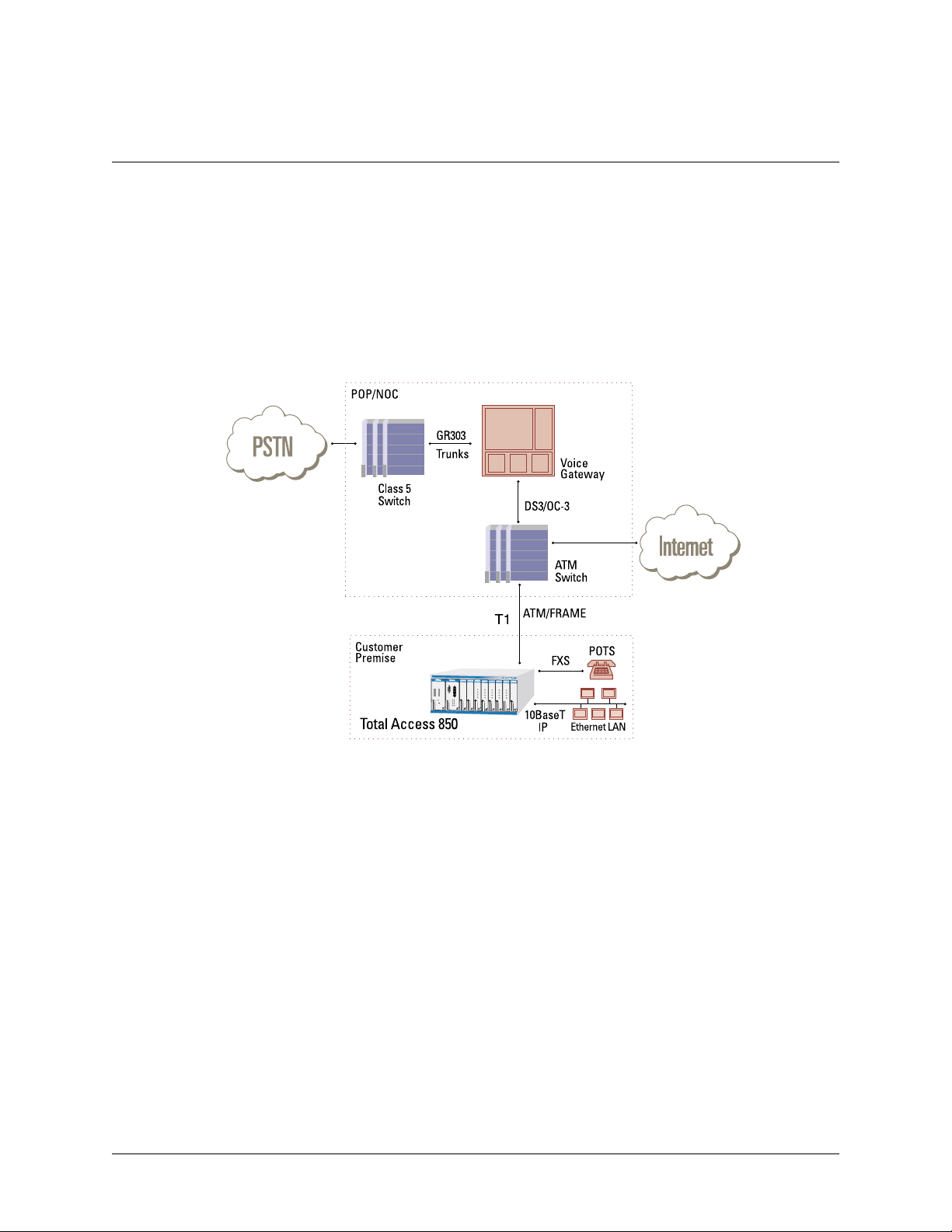
3. VOICE OVER ATM APPLICATION
You can upgrade the T1 RCU for VoATM by adding the Echo Canceller (see the Echo Canceller User Interface
Guide, document number61200384L1-31).The Echo Cancelleris used inATM voiceapplications that requireG.168
echo cancellation. The RCU must be using Voice Over ATM firmware to be able to use this module. The module is
available with and without ADPCM.
Figure 1 shows a typicalVoATM application. The TA 850 connects to the ATM Network to provide both voice and
high speed data from a single platform.
PSU
RCU
BLANK
BLANK
FXS
1
L
6
0
0
5
7
1
1
FXS
1
L
6
7
3
0
0
2
1
FXS
FXS
FXS
1175099L1
C
TX
-48V
20 Hz
R
N
3
A
E
3
F
T
TX
A
T
RX
A
M
M
M
O
P
P
N
RX
PWR
T1 ALARM
BANK
T1 TEST
T1 ERROR
ACO
V.35 TD
V.35 RD
ETH LI
ETH TX/RX
BLANK
1175099L1
1175408L1
1175408L1
1175408L1
1175408L1
1175408L1
1175099L1
BUSY
BUSY
BUSY
BUSY
BUSY
1
1
1
1
1
2
2
2
2
2
3
3
3
3
3
4
4
4
4
4
Figure 1. V oice over ATM
TA 8 50 User Manual © 2001, ADTRAN, Inc.
Page 21
61200375L1-1
T1 RCU VoATM UIG/61200376L2-31A
Page 21 of 72
Refer to the next section, Configuring the TA 850, for general configuration instructions.
Refer to the appendices at the end of this document for informationon usingthe TA 850 in specific
applications:
• Appendix D. Voice Gateway Quick Start Procedure (Voice Turn up) on page 65.
• Appendix E. RFC1483 Quick Start (IP Routing) on page 67.
• Appendix F. RFC1483 Quick Start (IP Routing with NAT) on page 69.
• Appendix G. RFC1483 Quick Start(Bridging) on page 71.
4. INSTALLING A MODULE
After installing the TA 850 Base Unit and connecting the required cables, you can install necessary modules.
TA 850
Remove the 20 Hz fuse before exposing backplane or accessing channel units.
Electronic modules can be damaged by s tatic electrical discharge. Before handling modules, wear
an antistatic discharge wrist strap to prevent damage to electronic components.Place modules in
antistatic packing material when transporting or storing. When working on modules, always place
them on an approved antistatic mat that is electrically grounded.
Individual access modules insert from the front. A lockingbar holds the modules in place for added security. Disengaging the captured screw allows removal of the locking bar. All wiring connections terminate on the backplane.
The following step/action table tells how to install a module.
Instructions for Installing Module in the TA 850
Step Action
1
2
3
Hold the module by the faceplatewhile supporting the bottom side.
Align the module edgesto theguide groovesfor the designated slot.
Insert the module until the edge connector seats firmly into the
backplane.
4
5
© 2001, ADTRAN, Inc. TA 850 User Manual
Lock theunit in place by pushing in on the locking lever.
Connect the cables to the associated device(s).
Page 22
61200375L1-1
TA 850
T1 RCU VoATM UIG/61200376L2-31A
Page 22 of 72
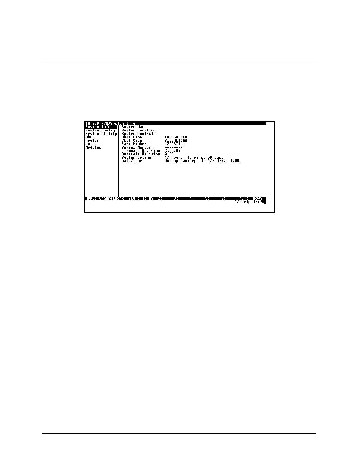
5. CONFIGURING THE TA 850 System Info
YSTEMINFO
The S
Figure 2 displays the submenus available when you select this menuitem.
menu provides basic information about the unit and contains data fields for editing information.
Figure 2. System Information Menu
>System Name
Provides a user-configurable text string for the name of the TA 850. This name can help you distinguish between different installations. You can enter up to 40 alpha-numeric characters in this field,including spacesand special characters (suchas an underbar). This name will appear on the top line of all screens.
>System Location
Provides a user-configurable text stringfor thelocation of theTA 850. Thisfield is to helpyou keep trackof the actual
physical location ofthe unit. Youcan enter up to 40alphanumeric characters inthis field, including spaces andspecial
characters (such as an underbar).
>System Contact
Provides a user-configurable text string for a contact name. You can use this field to enter the name, phone number,
or email address of a person responsible for the TA 850 system. You can enter up to 40 alpha-numeric characters in
this field,including spaces and special characters (such as an underbar).
>Unit Name
Product-specific name for the controller card.
>CLEI Code
CLEI code for the controller card.
TA 8 50 User Manual © 2001, ADTRAN, Inc.
Page 23

> Part Number
ADTRAN part number for the controller card.
>Serial Number
Serial numberof the controller card.
>Firmware Revision
Displays the current firmware revision level of the controller.
>Bootcode Revision
Displays the bootcode revision.
>System Uptime
Displays the length of time since the TA 850 system reboot.
61200375L1-1
TA 850
T1 RCU VoATM UIG/61200376L2-31A
Page 23 of 72
>Date/Time
Displays the current date and time, including seconds. Thisfield can be edited. Enter the timein 24-hour format (such
as 23:00:00 for 11:00 pm). Enter the date in mm-dd-yyyy format(for example, 10-30-1998).
Each time you reset the system, this value resets to 0 days, 0 hours, 0 min and 0 secs.
© 2001, ADTRAN, Inc. TA 850 User Manual
Page 24

61200375L1-1
TA 850
T1 RCU VoATM UIG/61200376L2-31A
Page 24 of 72
System Config
Set up the TA 850 operational configuration from the S
this menu.
Figure 3. System Configuration Menu
>T1 Timing Mode
Selects the timing source for the entire system.
Network
The system’s clock is recovered from the network (T1).
YSTEMCONFIG
menu. Figure 3 shows the items included in
Internal
The system’s clock is generated internally by the TA 850 controller.
>Telnet Access
O
O
N
Sets Telnet access to
or
FF
.
>Telnet User List
Up to four users can be configured for access to the TA 850. Each user can be assigned a security level and time out.
Name
A text string of the user name for this session.
Authen Method
The user can be authenticated in two ways:
P
ASSWORD
R
ADIUS
Password
When the authenticating method is password, this text string is used for the password.
TA 8 50 User Manual © 2001, ADTRAN, Inc.
The Password field is used to authenticate the user.
The Radius client is used for authenticating the user.
Page 25

61200375L1-1
TA 850
T1 RCU VoATM UIG/61200376L2-31A
Page 25 of 72
Idle Time (1-255)
This sets the amount of time you can be idle before you are automatically logged off.
Level
This is the security level granted to the user.
>SNMP Menu
The TA 850 is an SNMP agent.It can respond to Gets and Sets,and cangenerate traps. These two listsset u p the manager, communities, and levels.
Access
N
When set to
based on the configuration.
Communities
This listis used to set up to eight SNMP communities names that theTA850 will allow. Factory default sets
the community “public” with “Get” privileges only.
O, S NMP access is denied. When set toON (def), the TA 850 will respond to SNMP managers
Name
This is a text string for the community name.
Privilege
The access for this manager can be assigned three levels.
N
ONE
G
ET
GET/S
Manager IP
ET
No access is allowed for this community or manager.
Manager can only read items.
Manager can read and set items.
This is the IP addressof SNMP manager. If set to 0.0.0.0, any SNMP manager can access the TA 850
for thiscommunity.
Traps
The TA 850 can generate SNMP traps. This list allows up to four managers to be listed to receive traps.
Manager Name
This is the text string describing the name of the entry. It is intended for easy reference and has no bearing onthe SNMP trap function.
Manager IP
This is the IP address of the manager that is to receive the traps.
© 2001, ADTRAN, Inc. TA 850 User Manual
Page 26

61200375L1-1
TA 850
T1 RCU VoATM UIG/61200376L2-31A
Page 26 of 72
>Maint Port Menu
The TA 850’s VT 100
CRAFT
port can be accessed in two ways. One is a DB 9 located on the front, and the other is
an RJ 48 located on the rear.The setup for these ports is underthis menu.
Password Protect
N
O
When set to
, the maintenance port isnot password protected.When
a password upon startup.
Password
This is the text string that is used for comparison when password protecting the maintenance port. By
default, no password is entered.
The security level for the maintenance port isalways set to 0. This gives full access to all menus.
Passwords are case-sensitive.
O
N
(def), the TA 850 will promptfor
Instructions for Changing Passwords
Step Action
1
2 Type the new password in the E
3
Select the
Type the new password again in the C
P
ASSWORD
field—a new
NTER
P
ASSWORD
field.
ONFIRM
field displays.
field.
The password can contain up to 12 alphanumeric characters.You
can also use spaces and special characters in the password.
Baud Rate
This is the asynchronous rate that the maintenance port will run. The possible values are 300, 1200, 2400,
4800, 9600 (def), 19200, 38400, and 57,600.
Data Bits
This isthe asynchronous bit rate that the maintenance port will run. The possible values are 7 or 8 (def) bits.
Parity
This is the asynchronousparity that the maintenance port will run. The possible values are
E
VEN
or
.
N
ONE
(def),
O
DD
,
TA 8 50 User Manual © 2001, ADTRAN, Inc.
Page 27

Stop Bits
This is the stop bit used for the maintenance port. The possible values are 1 (def), 1.5 or 2.
>Network Time
61200375L1-1
TA 850
T1 RCU VoATM UIG/61200376L2-31A
Page 27 of 72
The TA 8 50 unittime can be enteredmanually from the S
SNTP server.The N
ETWORKTIME
menu includes all parameters relatingto how the unit communicateswith thetime
server.
Server Type
The server type defines which port the TA 850 will listen on to receive timing information from the time
server.
NT Time
The TA 850 will receive time from an NT server running SNTP software on its TIME port.
SNTP
The TA 850 will receive time directly from an SNTP server.
Active
This network timing feature can be turned on andoff. Itdetermines whether the unit will request and receive
time from a time server.
Time Zone
There are several time zones available for the time to be displayed in. All time zonesare based off of Greenwich Mean Time (GMT).
Adjust for Daylight Saving
Since some areas of the world use Daylight Savings Time, theTA 850 is designed to adjust the time on the
first Sundayin April and the last Sunday in October accordingly if this option is turned on.
YSTEMINFO
menu, or the unitcanreceive time froman NTP/
Host Address
This is the IP address of the time server that theTA 850 will request and receive time from.
Refresh
This is the interval of time between each request theTA 850 sends out tothe time s erver. A smaller refresh
time guarantees that the unit receives the correct time from the server and corrects possible errors more
quickly, but it is more taxing on the machine. A range of refresh times is available for the user to decide
which is best for their unit.
Status
This displays thecurrent status ofthe time negotiation process. Ifan error isdisplayed, check allconnections
and configurations to try to resolve the problem.
© 2001, ADTRAN, Inc. TA 850 User Manual
Page 28
61200375L1-1
TA 850
T1 RCU VoATM UIG/61200376L2-31A
Page 28 of 72
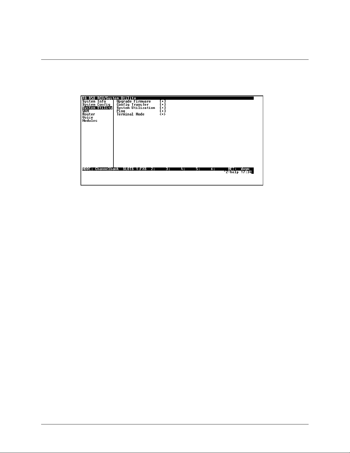
System Utility
Use the S
YSTEMUTILITY
menu to view and setthe system parameters shown in Figure 4.
Figure 4. System Utility Menu
>Upgrade Firmware
Updates firmware when TA 850 enhancements are released. Two transfer methods are available for use inupdating
the TA 850 system controller.
Transfer Method
The two methods for upgrading are XMODEM and TFTP. (See Appendix A. Updating TA 850 Firmware
using XMODEM on page 53 and Appendix B. Updating TA 850 Firmware using TFTP on page 57 for more
information.) TFTP requires a TFTP server running somewhere on t he network. The TA 850 starts a TFTP
client functionwhich gets the upgrade code from the TFTP server. SelectingXMODEM will load the
upgrade code through the
CRAFT
port using any PC terminal emulator with xmodem capability.
TFTP Server Address
This is required when the transfer methodis TFTP. It is the IP address or domain name (ifDNS is configured) of the TFTP server.
TFTP Server Filename
This is required when the transfer method is TFTP. It is the case-sensitive file name which contains the
upgrade code.
Transfer Status
This appears when TFTP is used. It displays the statusof the transfer as it happens. Any error or success
message will be displayed here.
TA 8 50 User Manual © 2001, ADTRAN, Inc.
Page 29

T1 RCU VoATM UIG/61200376L2-31A
Start Transfer
This activator is used when the configurable items in this menu are complete.
61200375L1-1
TA 850
Page 29 of 72
Before using S
TARTTRANSFER
, the TA 850should have avalid IP address, subnetmask, and default
gateway (if required).
Abort Transfer
Use this activator to cancel any TFTP transfer in progress.
>Config Transfer
Used only with TFTP transfers. Sends a file containing the TA 850 configuration to a file on a TFTP server using the
TFTP protocol. C
ONFIGTRANSFER
same configuration with multiple TA 850 units. In addition, C
aTFTPserver.
To support these transfers, ADTRANdelivers a TFTP program with the TA 850 called TFTP Server. You can configure any PC running Microsoft Windows with this software, and store aconfiguration file. See Appendix B. Updating
TA 850 Firmware using TFTP on page 57 for details on how to use TFTP Server.
Before using C
default gateway (if required).
also lets you save the TA 850 configuration as a backup file, so you can use the
ONFIGTRANSFER
ONFIGTRANSFER
, the TA 850 should have a valid IP address, subnet mask, and
can retrieve a configuration file from
Only one configuration transfersession (upload or download) can be active at a time.
Transfer Method
Displays the method used to transfer the configuration fileto or from a server. Currently,you must use TFTP.
Transfer Type
INARY
Only B
transfers are currently supported.
TFTP Server IP Address
Specifies the IP address of the TFTP server. Get this number from your system administrator.
TFTP Server Filename
Defines the name of the configuration file that you transfer to or retrieve from the TFTP server. The default
name is
ta 850.cfg
, but you can edit this name.
Current Transfer Status
Indicates the current status of the update.
© 2001, ADTRAN, Inc. TA 850 User Manual
Page 30

61200375L1-1
TA 850
T1 RCU VoATM UIG/61200376L2-31A
Page 30 of 72
Previous Transfer Status
Indicates the status of the previous update.
Load and Use Config
Retrieves the configuration file specified in theTFTP S
command, enter
Y
to begin or enterNto cancel.
If you execute this command, the TA 850 retrieves the configuration file, reboots, then restarts using the
new configuration.
Save Config Remotely Saves the configuration file specified in TFTP S
ERVER
S
IP A
DDRESS
. To start this command, enterYto begin or enterNto cancel.
ERVERFILENAME
ERVERFILENAME
field from the server. To start this
to the server identified in TFTP
Before using this command, you must have identified a valid TFTP server in TFTP S
A
DDRESS
.
>Ping
Allows you to send pings (ICMP requests) to hosts. The following items are under this menu:
Only one ping session canbe active at a time.
Start/Stop
Activator to start and cancel a ping test.
Host Address
IP addressor domain name (if DNS is configured) of device to receive the ping.
Size (40-1500)
Total size of the ping to send. Range is 40 (def) to 1500 bytes.
# of Packets
0
Total packets to send every2 seconds. Setting this to
allows the client to ping continuously.
ERVER
IP
#Transmits
Total packets sent (read only).
# Receives
Total packets received (read only).
%Loss
Percentage loss based on ping returned from host (read only).
TA 8 50 User Manual © 2001, ADTRAN, Inc.
Page 31

Configuring WAN Settings –ATM Config
61200375L1-1
TA 850
T1 RCU VoATM UIG/61200376L2-31A
Page 31 of 72
Use the WANmenu (Figure 5) to access the ATM C
Figure 5. WAN Menu
ONFIG
Use the ATM C
menu (Figure 6) to set the parameters listed below the figure.
ONFIG
menu.
Figure 6. ATM Config Menu
>Idle Cells
DLECELLS
The I
format must be configured for either ATM F
particular circuit will cause poor performance at the ATM layer.
This setting must match the configuration setting of the ATM switch or DSLAM at the other end of
the circuit.
© 2001, ADTRAN, Inc. TA 850 User Manual
ORUM
or ITU. Configuring this settingincorrectly for a
Page 32
61200375L1-1
TA 850
T1 RCU VoATM UIG/61200376L2-31A
Page 32 of 72
>Data Scrambling
D
ATASCRAMBLING
can be E
NABLED
or D
ISABLED
for cell traffic.Configuring this settingincorrectly fora particular
circuit will cause poor performance at the ATM layer.
This setting must match the configuration setting of th e ATM switch or DSLAM at the other end of
the circuit.
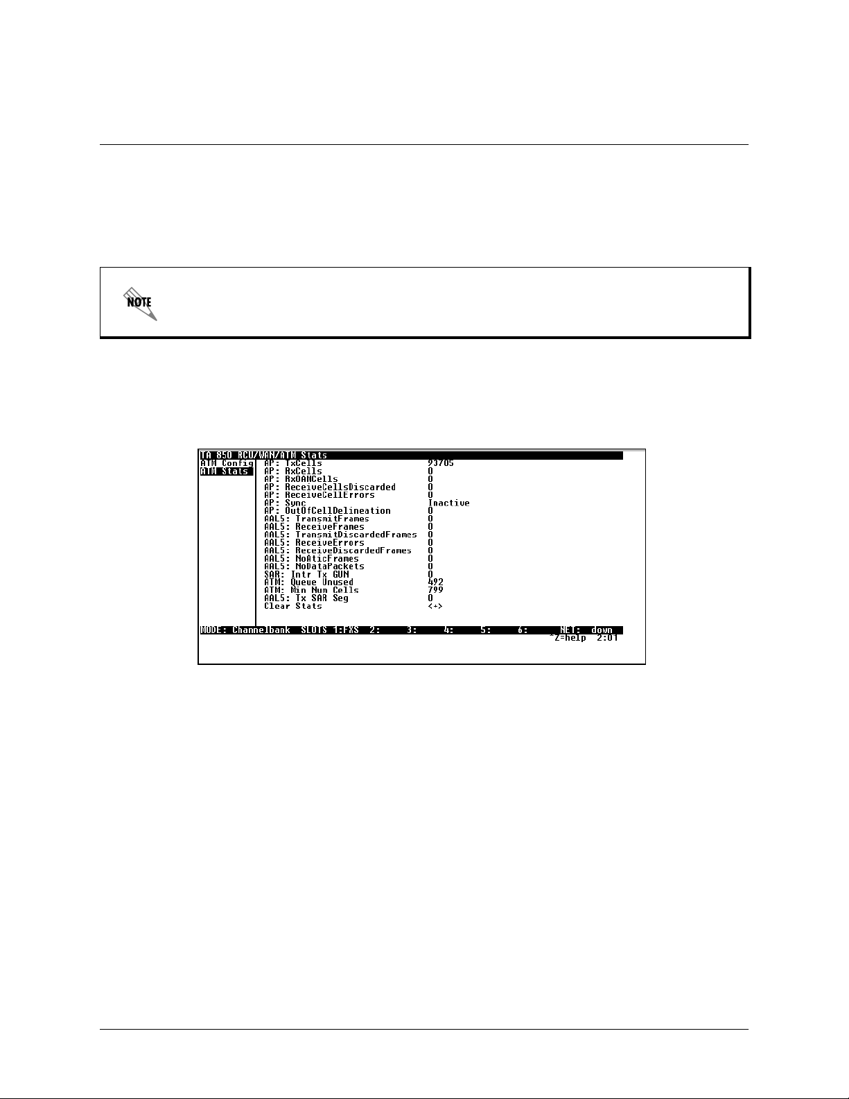
Configuring WAN Settings –ATM Stats
Use the WANmenu (Figure 5 on page 31)to access the ATM S
below the figure.
Figure 7. ATM Stats Menu
>AP: Tx Cells
This is the number of cells transmitted.
>AP: Rx Cells
This is the number of cells received.
TATS
menu (Figure 7) and viewthe parameters listed
>AP: Rx OAM Cells
This is the number of OAM cells received
>AP: Receive Cells Discarded
This is the number of cells received and discarded. An incrementing count in thisfield could indicate a configuration problem with the ATM layer.
>AP: Receive Cell Errors
This is the number of cells received with an HEC error.
TA 8 50 User Manual © 2001, ADTRAN, Inc.
Page 33

>AP: Sync
This indicates cell delineation at theATM layer.
>AP: Out Of Cell Delineation
This indicates loss of cell delineation at theATM layer.
>AAL5: Transmit Frames
This is the number of AAL5 frames transmitted.
>AAL5: Receive Frames
This is the number of AAL5 frames received.
>AAL5: Transmit Discarded Frames
This is the number of AAL5 frames discarded.
>AAL5: Receive Errors
This is the number of AAL5 errors received.
61200375L1-1
TA 850
T1 RCU VoATM UIG/61200376L2-31A
Page 33 of 72
>AAL5: Receive Discarded Frames
This is the number of AAL5 frames discarded.
>AAL5: No ATM Frames
This is for internal use only.
>AAL5: No Data Packets
This is for internal use only.
>Clear Stats
This is used to clear the counters on this menu screen.
© 2001, ADTRAN, Inc. TA 850 User Manual
Page 34
61200375L1-1
TA 850
T1 RCU VoATM UIG/61200376L2-31A
Page 34 of 72
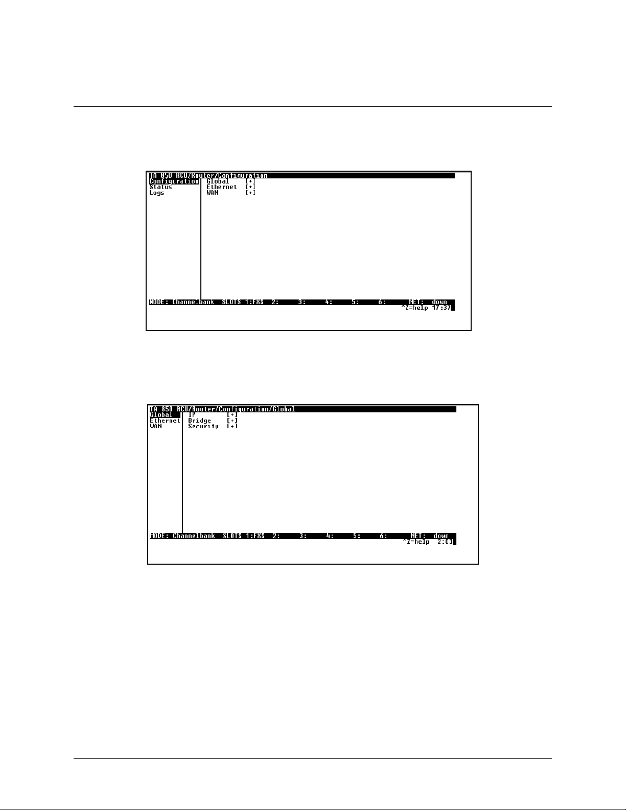
Configuring the Router – Configuration
Use the R
>Global
OUTER/CONFIGURATION
Use the G
LOBAL
menu (Figure 9) to set up general router functions.
menu (Figure 8) to acces s the G
LOBAL
, E
Figure 8. Router/Configuration Menu
THERNET
,andWANmenus.
Figure 9. Global Menu
IP
This is used for general IP configuration.
Mode
This item controls how the 850 handles IP r outes. When this option is set to ON(def), the 850will
advertise and listen to routes from other IP routers. If O
FF
, the route table is still used, but only static
routes areused for routing IP packets and only the Ethernet port is used. IP packets can be sent over the
WAN, but only when bridged.
TA 8 50 User Manual © 2001, ADTRAN, Inc.
Page 35

Static Routes
Use this menu to enter static routes to other networks.
A
CTIVE
Adds this static route entry to the IP routing table
when set to Y
ES
(def) and removes it (if it was pre-
viously added) if set to N
IP A
DDRESS
The IPaddress of the host or network address of the
device beingrouted to.
S
UBNETMASK
Determines the bits in the previous IP address that
are used. If thisis to be a hostroute,it must beset to
all ones (255.255.255.255).
G
ATEWAY
TheIPaddress of the router to receive the forwarded
IP packet.
HOPS
The number of router hops required to get to the network or host. Maximum distance is 15 hops.
PRIVATE
WhensettoNO,the TA 850 will advertise this static
route using RIP. Setting toY
is kept private.
61200375L1-1
T1 RCU VoATM UIG/61200376L2-31A
Page 35 of 72
O
.
ES
means that theroute
TA 850
DHCP Server
DHCP M
ODE
When set to ON, theTA 850 acts as a DHCP server
and will dynamically assign IP, network mask, default gateway, and DNS addresses to any device
which transmitsa broadcastDHCP request. The addresses assigned are based on the TA 850’s own IP
address and will be within the same network.
DHCP R
ENEWALTIME
The number of hours that the DHCP server should
allow the device before it is required to send a new
DHCP request. The default is 15 hours, and0 represents an infinite lease.
Domain Names
Enter the 850's domain name and the primary and secondary DNS servers in thismenu.
D
OMAINNAME
Text string used to represent the domain name
used by the TA 850.
P
RIMARY
DNS
First server to which domain name requests are
sent.
S
ECONDARY
DNS
Server used as a backup, in case the primary address does not respond to the request.
P
RIMARY
NBNS/WINS
Server to which NT domain name requests are
sent.
S
ECONDARY
NBNS/WINS
Server used when there isno response from the
primary server.
© 2001, ADTRAN, Inc. TA 850 User Manual
Page 36

61200375L1-1
TA 850
T1 RCU VoATM UIG/61200376L2-31A
Page 36 of 72
UDP Relay
This menu configures the 850 to act as a UDP relay agent for applications requiring a response from
UDP hosts that are not on the same network segment as their cl ients.
Mode
When this option is set toON(def), the TA 850 will act as a relay agent.
UDP Relay List
Up to four relay destination servers can be specified in this list.
R
ELAYADDRESS
UDP P
ORTTYPE
STANDARD (def)
S
PECIFIED
UDP P
ORT
1, 2, 3
This is the IP address of the server that will receive the relay packet.
The following standard UDP protocols are
relayed when set: DHCP, TFTP, DNS, NTP
(Network Time Protocol, port 123, NBNS
(NetBios Name Server, port 137),NBDG
(NetBIOS Datagram, port 138), and BootP.
When set, the UDP port (1 to65535) can be
specified in the UDP Port columns (up to
three perserver).
Used for specifying UDP ports to be relayed.
UDP P
These fields only apply when
S
PECIFIED
set to
.
ORTTYPE
is
Bridge
RIDGE
The B
menu is used to set up the bridge parameters for the 850. The bridgingfunction runs at the
Media Access Control (MAC) level which allows any protocol packets that run over Ethernetto be forwarded. Bridging can run concurrently with IP. However, when IP routing is active, IP packets (which
include ARP packets) are not bridged.
Mode
This is used to enable the bridge function.
Address Table
The 850 automatically maintains atable of MAC addresses detectedand associates those addresses with
the LAN or WAN port from which they were received.
A
GING
The maximum time an idleMACaddress remains in
the table beforebeing removed. Thevalue is inminutes.
F
ORWARDPOLICY
When this parameter is set to U
NKNOWN
(def), any
bridge packet with a destinationMAC address that
is not in the bridge table is forwarded to all other
ports. Whenset to K
NOWN
, the packet with the unknown destination MAC address is dropped and is
not forwarded.
TA 8 50 User Manual © 2001, ADTRAN, Inc.
Page 37

61200375L1-1
T1 RCU VoATM UIG/61200376L2-31A
Page 37 of 72
Security
Filter Defines
The TA 850 can filter packets based on certain parameters within the packet. The method used by the
TA 850 allows the highest flexibility for defining filters and assigning them to aPVC. The filters are set
up in two steps: (1) defining the packet types, and (2) adding them to a list under the PVC. This menu is
used to define the individual filter defines based on packet type.
Filter Defines /MAC Filter Defines
The MAC filter is applied to bridge packets only. Bridge packets which are forwarded by the bridge
functionality of the TA 850 are defined here.Up to 32 MAC defines can be specified.
N
AME
SRCA
DDR
Identifies the filter entry.
48-bit MAC source address used for
comparison. (hexadecimal format)
SRC MASK
Bits in the MAC source address which are
compared. (hexadecimal format)
D
ESTADDR
48-bit MAC destination address used for
comparison. (hexadecimal format)
D
ESTMASK
Bits in the MAC destination address used for
comparison. (hexadecimal format)
MAC TYPE
16-bit MAC type field used for comparison.
(hexadecimal format)
T
YPEMSK
Bits in theMAC type fieldused for comparison.
(hexadecimal format)
TA 850
Filter Defines /Pattern Filter Defines
The pattern filter is applied to bridge packets only. That is any packet which is forwarded by the bridge
functionality of the TA 850. Up to 32 pattern defines can be specified.
N
AME
O
FFSET
Identifies the filter entry.
Offset from beginning of packet of where to
start the pattern comparison.
P
ATTERN
64 bits used for comparison. (hexadecimal
format)
M
ASK
Bits in the pattern tobe compared.
(hexadecimal format)
Filter Defines /IP Filter Defines
The IP filter defines apply to any IP packet, whether it is routed or bridged. Up to 32 IP defines can be
specified.
N
AME
IP S
RC
Identifies the filter entry.
IP address compared to the source address.
(dotted decimal format)
© 2001, ADTRAN, Inc. TA 850 User Manual
Page 38

61200375L1-1
TA 850
T1 RCU VoATM UIG/61200376L2-31A
Page 38 of 72
SRCM
ASK
IP D
EST
D
ESTMASK
SRCP
ORT
SRCP
ORT
C
MPR
Bits which are used in the source comparison.
(dotted decimal format)
IPaddresscomparedtothedestinationaddress.
(dotted decimal format)
Bits which are used in the destination
comparison. (dotted decimal format)
IP source port number used for comparison
Range: 0to 65535. (decimal format)
Type ofcomparison that is performed.
= means ports equal to
not = means port not equal to
> means port greater than
DSTP
ORT
DSTP
ORT
C
MPR
P
ROTO
P
ROTOCMPR
< means port less than
None - means the source port is not compared
IP destination port number used forcomparison
Range: 0to 65535. (decimal format)
Type ofcomparison that is performed
= means ports equal t o
not = means port not equal to
> means port greater than
< means port less than
None - means the destination port is not
compared
Protocolused for comparison.Range: 0 to255.
(decimal format)
Type ofcomparison that is performed
= means protocols equal to
not = means protocols not equal to
> means protocols greater than
< means protocols less than
None means the protocol is not compared
TA 8 50 User Manual © 2001, ADTRAN, Inc.
Page 39
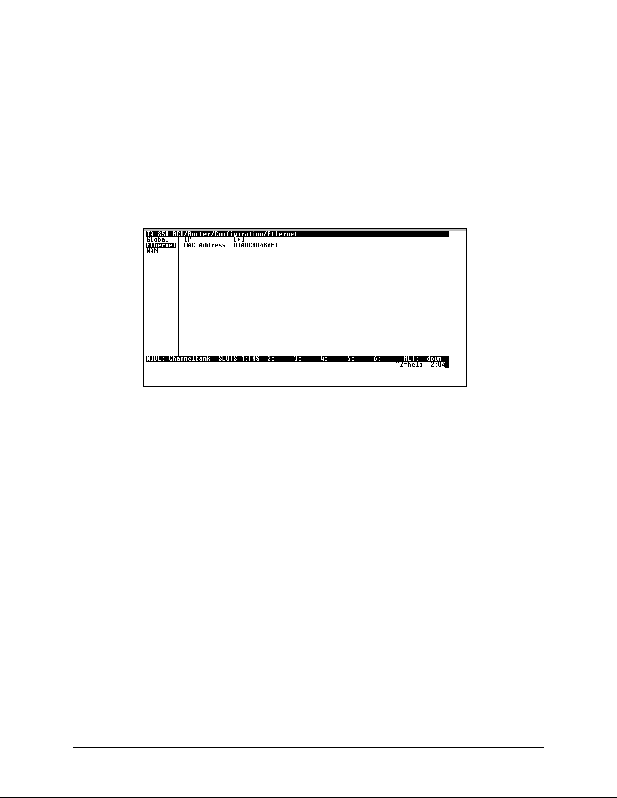
>Ethernet
Use the E
TCP E
THERNET
T1 RCU VoATM UIG/61200376L2-31A
ST
Yes - only when TCP established
No - only when TCP not established
Ignore - ignore TCP flags
menu (Figure 10) to configure the Ethernet port on the 850.
61200375L1-1
TA 850
Page 39 of 72
Figure 10. Ethernet Menu
IP
This is used to setup the IP addresses for the LAN on the 850
IP Address
The IP address assigned to the 850's Ethernet port is set here. This address must be unique within the
network.
Subnet Mask
This is the IP network mask that is to be applied to the 850's Ethernet port.
Default Gateway
The default gateway is used by the 850 to send IP packetswhose destination address is not found in the
route table.
© 2001, ADTRAN, Inc. TA 850 User Manual
Page 40

61200375L1-1
TA 850
T1 RCU VoATM UIG/61200376L2-31A
Page 40 of 72
RIP
Use this menu to enable RIP on the LAN interface.
M
ODE
P
ROTOCOL
M
ETHOD
N
ONE
S
PLITHORIZON
POISON REVERSE
DIRECTION
TX AND RX (def)
TX ONLY
RX O
NLY
V2 S
ECRET
(def)
Enables or disables RIP.
Specifies the RIP protocol. Choices areV1(def)
(which is RIP version 1) or
V2
(RIP version 2).
Specifies the way the RIP protocol sends outits
advertisements. Choicesare given below.
All routes in the router table are advertised
with no modification of the metrics.
Only routesnot learned from this circuit are
advertised.
All routes are advertised, but the routes
learnedfromthisportare “poisoned”with an
infinite metric.
Allows the direction at which RIP advertisements are sent and listened to be specified.
RIP advertisements are periodically
transmitted and are listened to on this port.
RIP advertisements are periodically
transmitted but are not listened to on this
port.
RIP advertisements are not transmitted on
this port, but are listened.
Enter the secret used by RIP version 2 here.
Proxy ARP
This feature allows the network portionof a group of addresses to be shared among several physical
network segments. The ARP protocol provides a way for devices to create a mapping between physical
addresses and logical IP addresses. Proxy ARP makes use of this mapping feature byinstructing a
router toanswer ARP requests as a "proxy" for the IP addresses behind one of its ports. The device
which sent the ARP request will then correctly assume that it can reach the requested IP address by
sending packets to the physical address that was returned. This technique effectively hides the fact that
a network has been (further) subnetted. If this option is set to Y
ES
, when an ARP request is received on
the Ethernet port the address is looked up in the IP routing table. If the forwarding port isnot on the
Ethernet port and the route is not the default route, the 850 will answer the request with its own hardware address.
MAC Address
This is a read-only MAC address programmed at ADTRAN.
TA 8 50 User Manual © 2001, ADTRAN, Inc.
Page 41

>WAN
61200375L1-1
TA 850
T1 RCU VoATM UIG/61200376L2-31A
Page 41 of 72
Use the WAN menu (Figure 11) to configure WAN settings on the 850.
Figure 11. WAN Menu
L2 Protocol
Displays the current L2 protocol -ATM (Read Only).
ATM
Use the ATM menu to setup Data PVCs for the router.
Description
This is the text description for the PVC.
VPI
ATM virtual port identifier.
VCI
This is the ATM virtual channel identifier.
Protocol
This is the protocol supported on the PVC.
RFC1483 IP
Use thisselection to support IP on this DLCI.
Active
This selection enables IP on this PVC.
Far - End IP Address
This is the address of the NEXT hop router on this interface.
IP netmask
This is the network mask used for this interface.
Local IP Address
This is the IP address for this PVC.
© 2001, ADTRAN, Inc. TA 850 User Manual
Page 42

61200375L1-1
TA 850
T1 RCU VoATM UIG/61200376L2-31A
Page 42 of 72
NAT
Use this menu to set up and use Network Address Translation on this interface.
N
ETWORKADDRESS
P
ORTTRANSLATION
P
M
T
NAT V
IP A
UBLIC
ODE
RANSLATIONTABLE
PUBLIC ADDRESS
M
P
P
P
M
P
M
T
DDRESS
ODE
ROTOCOL
UBLICPORTMODE
RIVATEADDRESS
ODE
RIVATEPORT
ODE
RANSLATEBODY
IEW
By enabling port translation, IP packets are modified
as they pass through this interface. During transmission, private addresses are translated into a single
public (NAPT) IP address. Incomingpackets are
translated from the public toprivate addressbased on
the protocol port numbers.Once enabled, you must
set up NAT for use.
The port translation requires at least a single real IP
address for translating. This value can use the IP assigned to the interface (or assigned via layer 2 protocol like PPP), obtained using DHCP client, or
staticallyspecifiedon this menu. If the address cannot
be learned, then it mustbe specified in order for the
translation to work.
Add translation entries to "fine tune" specialprotocols or specify private addresses.
The public IP address used for this translation
entry can be theNAPT IP addressassigned tothe
link or canbe specified.You specifyanaddress to
direct packets with certain protocols to different
servers.
The upper layer protocol that is to be monitored
for translation. For TCP and UDP, a port number
must also be specified.
The public destination port associated with this
entry can be specified to add more control over
certain types of traffic. The default, A
NYPORT
,
covers all port types.
The private IP address canbe specified to steer
certain protocols and ports to specific servers in
the private network. Likewise, internal hosts can
be steered to certain servers on the public
network. A new request from the public network
matching this entry’s public parameters will be
dropped ifthis mode is set to A
NYINTERNAL
.
The private destination port associated with this
entry can be specified to add more control over
certain types of traffic. Leave as A
NYPORT
to
cover all port types.
By default, the application payload in the packet
is scanned for occurrencesofthe private/public IP
addressinbinary or ASCII form. Set thisto
No
for
applications where this will cause problems.
Shows the protocols that areactivelybeing translated.
TA 8 50 User Manual © 2001, ADTRAN, Inc.
Page 43

61200375L1-1
TA 850
T1 RCU VoATM UIG/61200376L2-31A
Page 43 of 72
NAPT A
E
E
C
RIP
DDRESS
NTRYCOUNT
NTRYOVERFLOW
OUNT
Use this menu to enable RIP on the WAN interface. (See RIP on page 40 for description of options.)
RFC 1484 Bridge
This is used to enable bridge mode on this PVC.
Configuring the Router – Status
Use the R
screens give the user useful information for debugging the current routes in the 850.
OUTER/STATUS
menu to view and set the parameters shown in Figure 12. The R
Representsthe public address thatis being usedasthe
NAPT address.
The number of entries in the NAT table.
A count of the dropped entries due to low memory.
OUTER/STATUS
Figure 12. Router/Status Menu
>Session
This menu maintains statistics about the active ATM PVCs.
>ARP cache
This is a listing of the currently connected Ethernetport on the LAN.
>Bridge Table
This shows the detected MAC addresses and the interface to whichthey are associated.
>IP Routes
This shows the current routes in the 850 and their use.
>LAN Stats
This shows traffic over the LAN interface.
© 2001, ADTRAN, Inc. TA 850 User Manual
Page 44

61200375L1-1
TA 850
T1 RCU VoATM UIG/61200376L2-31A
Page 44 of 72
>IP Stats
This shows IP traffic through the 850.
Configuring the Router – Logs
The Logs menu(Figure 13) containslogs displaying importantinformation about therunning condition of the TA 850.
The logscan be set to capture diagnostics of error conditions only by way of a log level. The levels are divided upas
follows:
level 0 - Fatal event (causes reset)
level 1 - Critical event
level 2- Error event
level 3- Warning event
level 4 - Notify event
level 5- Informational event
level 6- Debugging event
Figure 13. Router/Logs Menu
Sys log Host
Set this tothe IP address or domainname (if DNSconfigured) of thesys log hostdevice. All log events aresent to this
device.
PPP Log
Information pertaining to the PPP negotiation and authentication is logged in the PPP log.
Connection Log
Information pertainingto the call placement and answering is logged in the Connection log.
Network Log
Information pertainingto routing protocols is placed in this log.
TA 8 50 User Manual © 2001, ADTRAN, Inc.
Page 45

T1 RCU VoATM UIG/61200376L2-31A
Each log (PPP log, Connection log, and Network log) contains thefollowing elements.
Active
When set to YES(def), PPP events below or equal the log level are logged into the log.
Wrap
When set to YES(def), new PPP events will overwrite old PPP events when the log is full. All logging
will stop when the log is full and set to N
Level
O
.
In order to log events, they must be at or below this level. Range is 0 to 6. The default is 3.
View
This menu displays the log list. The fields are as follows:
D
ATE/TIME
Date and time event occurred.
61200375L1-1
TA 850
Page 45 of 72
LEVEL
M
ESSAGE
Clear
This clears the log when activated.
Level associated with this event (0-6).
Text message for this event. If message is too
long to fit on the line, another event appears
below it continuing the message.
© 2001, ADTRAN, Inc. TA 850 User Manual
Page 46

61200375L1-1
TA 850
T1 RCU VoATM UIG/61200376L2-31A
Page 46 of 72
Configuring Voice Support – Config
Use the V
OICE/CONFIG
menu to view and set the parameters shown in Figure 14.
Figure 14. Voice/Config Menu
>Call Control
ALLCONTROL
The C
tween the TA 850 and the configured Gateway. The C
setting is usedto configure the correct Voice Gateway protocol for voice signaling control be-
ALLCONTROL
setting must be configured correctlybefore the
voice circuits will work correctly. The TA 850 supports Jetstream, Tollbridge, and CopperCom Voice Gateways.
>VPI
The VPIsetting is used to configure the TA 850 virtual path setting used to communicate with the configured Voice
Gateway.
>VCI
The VCI setting is used to configurethe TA850 virtual circuit setting used to communicate with the configuredVoice
Gateway.
TA 8 50 User Manual © 2001, ADTRAN, Inc.
Page 47
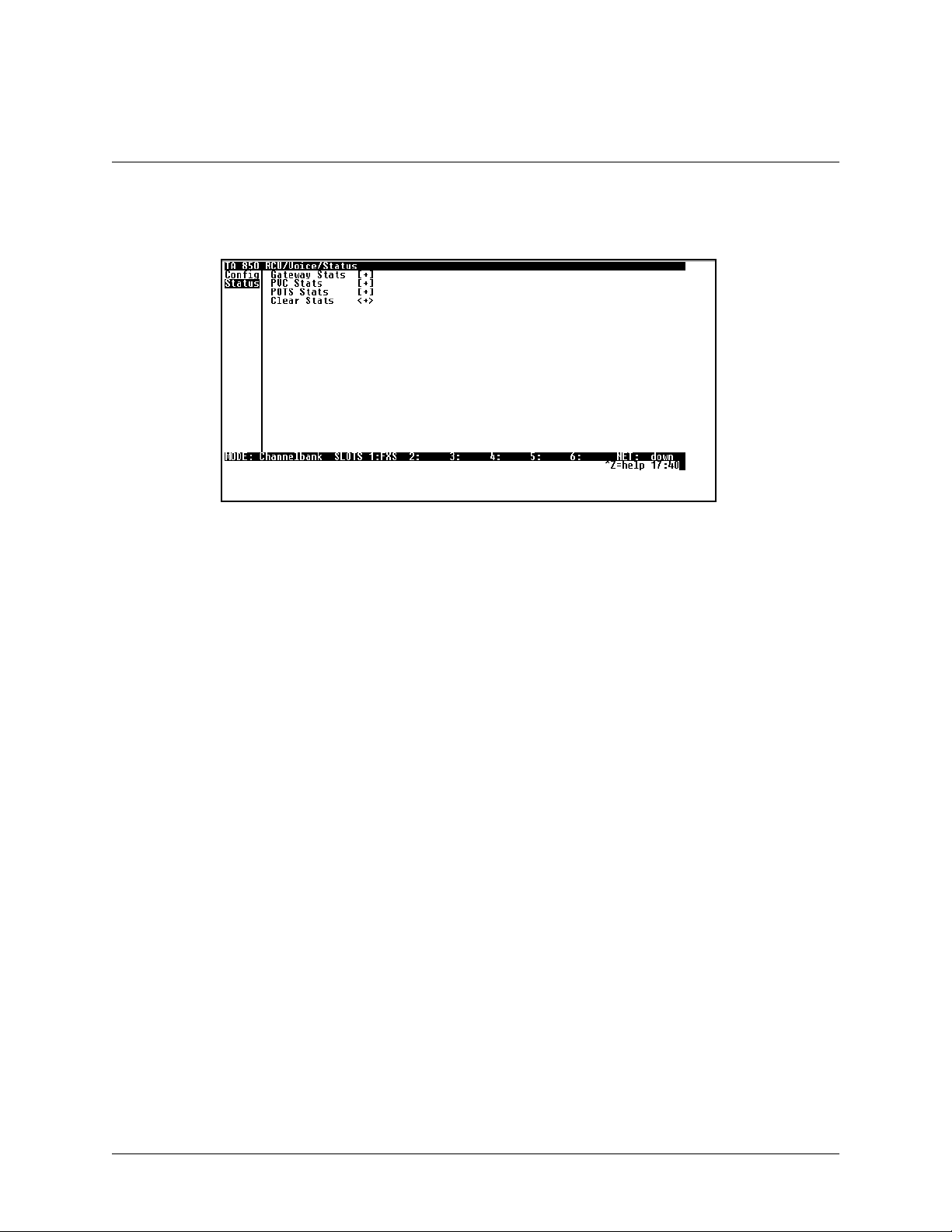
Configuring Voice Support – Status
61200375L1-1
TA 850
T1 RCU VoATM UIG/61200376L2-31A
Page 47 of 72
Use the V
OICE/STATUS
menu to view and set the parameters shown in Figure 15.
Figure 15. Voice/Status Menu
>Gateway Stats
ATEWAYSTATS
The G
menu shows the current state of the communication link between the TA 850 and the Voice
Gateway. The Gateway Link is indicated as U
the number of active calls in progress.
>PVC Stats
P
or D
OWN
. A count of management messages is indicated along with
The PVC S
TATS
menu shows the current state of the virtual circuit used between the Voice Gateway and the TA 850
IAD for voice signaling and voice payload delivery.
>POTS Stats
The POTS S
port basis, the user can determine which ports are active/inactive. Several statistics at this menu are used only for internal AD TRAN development. Task, Inserts, andDrops indicatorsare for internal use only.
TATS
menu shows real-timeindication status ofeach voice porton the TA 850.From this menu,on a per
>Clear Stats
LEARSTATS
The C
menu can be used to clear the counters used for Voice Status menus.
© 2001, ADTRAN, Inc. TA 850 User Manual
Page 48

61200375L1-1
TA 850
T1 RCU VoATM UIG/61200376L2-31A
Page 48 of 72
Managing the Modules – Modules
Use the M
ODULES
>Modules Table
ODULES
The M
these modules.
The table contains M
table indicates the type and slot number of each module installed in theTA 850and is used to manage
menu to view and set the parameters s hown in Figure 16.
Figure 16. Modules Menu
ENU
, A
LARM
, T
EST
,andS
TATUS
indicators/menus customized for each module.
TA 8 50 User Manual © 2001, ADTRAN, Inc.
Page 49
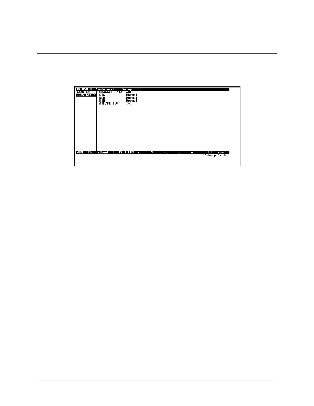
Managing the Modules –V.35 Setup
61200375L1-1
TA 850
T1 RCU VoATM UIG/61200376L2-31A
Page 49 of 72
Use the V.35 SE
TUP
menu to view and set the parameters shown in Figure 17.
Figure 17. V.35 Setup Menu
C
HANNELRATE
and EIAsettings are supported via this menu option. For all typical applications, these settings are
left in their default states.
>A TM/FR IWF
This menu contains the setup and status for the ATM/Frame Relay interworking functions.
Mode
ODE
The M
setting configures the V.35 port for FRF5 or FRF8 operation, depending upon the application
being supported.
FRF5
This is also known as Network Interworking. Use this mode for Frame Relay over ATM.
FRF8
This is also known as Service Interworking. In this mode, the TA 850 performs a translation between
Frame Relay and ATM protocols.
Configuration
ONFIGURATION
The C
menu is used to support the configuration of Frame-to-ATM interworking, signaling
formats, timeout values, and PVC settings.
© 2001, ADTRAN, Inc. TA 850 User Manual
Page 50

61200375L1-1
TA 850
T1 RCU VoATM UIG/61200376L2-31A
Page 50 of 72
The following settings are used for FRF5.
LANFR M
LANFR P
T392 (5-30)
FRN P
OLLTIMEOUT
ORTCONFIG
N
AME
ATM VPI
ATM VCI
DEM
AP
CLPI M
D/C
H
EADER
M
AINTPROTOCOL
MUXM
DLCI M
LANDLCI
NETDLCI
A
CTIVE
AINTPROTOCOL
AP
ODE
AP
Frame Relay maintenance or signaling protocol
between local V.35 port and the attached DTE
port, support ANSIAnnex A, CCITT Q933 Annex D, CISCO LMI or Static (no signaling).
T392forsignalingprotocol,typical value 15. No
meaning if Maint Protocol is Static.
Logical Frame Relay ports over ATM.Up to 4
ports are supported witheach port supporting up
NUM
to4DLCImappings.Goto
field.Typing"i"
or "I" willinsert another entry,and typing "d"or
"D" will delete one entry.
To identify your port.
Specifies the virtual path over which this
logical port is running.
Specifies the virtual circuit overwhich this
logical port is running.
Frame Relay to ATM demapping; default
value (FrnOnly, ATM 0) suggested.
ATM to Frame Relay CLPI map; default
value (Frn Only) suggested.
Set D/C field in the header to 0 or 1.
Header format; only 2 bytes supportednow.
Maintenance or signaling protocol over this
logical Frame Relay port. SupportAnnex A,
AnnexD,CISCOLMIorStatic.
ManyDLCIsor one DLCI mapping over this
port.
Actual D LCI mappings.
The DLCI configured over local V.35
Frame Relay port.
The DLCI configured over the WAN
side logical Frame Relay port.
Always active, not configurable.
TA 8 50 User Manual © 2001, ADTRAN, Inc.
Page 51

The following settings are used for FRF8.
61200375L1-1
TA 850
T1 RCU VoATM UIG/61200376L2-31A
Page 51 of 72
LANFR M
LANFR P
T392 (5-30)
FR/ATM PVC M
AINTPROTOCOL
OLLTIMEOUT
FR DLCI
ATM VPI
ATM VCI
T
RANSLATE
DEM
AP
F
ECNMAP
APPING
Frame Relay maintenance or signaling protocol
between local V.35 port and the attached DTE
port, support ANSIAnnex A, CCITT Q933 Annex D, CISCO LMI or Static (no signaling).
T392forsignalingprotocol,typical value 15. No
meaning if Maint Protocol is Static.
Up to 4 mappings are supported.
Frame Relay DLCI on V.35 port.
Specifies the virtual path to which DLCI is
mapped.
Specifies the virtualcircuit to whichDLCI is
mapped.
Translate or transparent mode between
Frame Relay frames and ATM cells.
Map Frame Relay DE bit to ATM CLPI bit,
Always 0, Always 1 or Convert eachother.
Map Frame Relay FECN bit toATM EFCI
bit, Always 0, Always 1 or Convert each
other.
© 2001, ADTRAN, Inc. TA 850 User Manual
Page 52

61200375L1-1
TA 850
T1 RCU VoATM UIG/61200376L2-31A
Page 52 of 72
TA 8 50 User Manual © 2001, ADTRAN, Inc.
Page 53

T1 RCU VoATM UIG/61200376L2-31A
Appendix A. Updating TA 850 Firmware using XMODEM
61200375L1-1
TA 850
Page 53 of 72
The TA 850 supports firmware updating using XMODEM transfer protocol via the base unit’s
DEM is found in the VT 100 terminal emulation application in the ADTRAN Utilities package and in most PC VT
100 communications software packages.
Make certain that the communications softwarepackage being used has flow control turned off.
Before beginning this procedure, you must obtain the appropriate update file from ADTRANTechnical Support at
(888) 4ADTRAN (423-8726).
An XMODEM download can be initiated by enabling the appropriate dip switch or by using the console menus. The
following materials are required.
• VT 100 terminal or PC with VT 100 terminal emulation software
• XMODEM software
To prevent electrical shock, do not install equipment in a wet location or during a lightning
storm.
CRAF T
port. XMO-
Electronic modules can be damaged by s tatic electrical discharge. Before handling modules, wear
an antistatic discharge wrist strap to prevent damage to electronic components.Place modules in
antistatic packing material when transporting or storing. When working on modules, always place
them on an approved antistatic mat that is electrically grounded.
Updating Firmware via the Dip Switch
Perform the Steps Below in the Order Listed
1. Using a VT 100 terminal emulation communication software package which contains XMODEM protocol support, log in toTA 850. Set the transmit rate of the emulation software to
9600 baud.
© 2001, ADTRAN, Inc. TA 850 User Manual
Page 54

61200375L1-1
TA 850
T1 RCU VoATM UIG/61200376L2-31A
Page 54 of 72
2. Remove the RCU module from the chassis and flip the
the right of the unit if you are facing it).
The dip switch is red and is located at the top edge ofthe card.
Only the first two dipswitches on the RCU are used.With the first dip switch down (to the right of
the unitif you are facingit), the unit boots up in a mode to update the firmware. With the second dip
switch down, the unit factory defaults at startup.
until a menu appears.
3. Press
Enter
To shorten transmit time, select the option from the menu to change the transmit rate to 115.2 baud
or the highest rate supported by the terminal emulation software. If this transmit rate is changed,
change emulation software properties to match this rate and disconnect and connect again. Press
Enter
again until the menu appears.
dip switch to down or open (to
SW1
4. Choose option 1, B
EGIN
OWNLOADNOW
, from the menu to start the XMODEM file
XMODEM D
download.
5. Press
at the S
Y
TARTFLASHDOWNLOADNOW
prompt to continue with the XMODEM file trans-
fer.
When TA 850 is ready to receive the XMODEM upload, the menu screen will display
Flash . . . download file now
. If this does not appear, please review the steps above for possible
Transmit
configuration errors.
6. From the terminal emulation software, begin the XMODEM upload by using the appropriate
command sequence. (If necessary, refer to terminal emulation software documentation for
help. Also, when specifying the filename, ensure that the file transferred is the one provided by ADTRAN. Otherwise, the update will not complete successfully.)
Because XMODEM data is being transferred in-band through the menuinterface, the VT 100
menus of TA850 willbe inoperable from the
CRAFT
port.
TA 8 50 User Manual © 2001, ADTRAN, Inc.
Page 55

61200375L1-1
TA 850
T1 RCU VoATM UIG/61200376L2-31A
Page 55 of 72
7. When the update has successfully completed, T
RANSFERCOMPLETE
appears in the terminal
window. If an error occurs during the update, an error message will display in the terminal
window. If this occurs, return to Step 3 and attempt the update again. If the same error
occurs, contact ADTRAN Technical Support.
8. After the T
return dip switch
RANSFERCOMPLETE
to the closed or off position. Reinsert the RCU module.
SW1
message has been displayed, pull the RCU card again and
9. Change the emulation software properties to 9600 baud. Disconnect and connect to the
unit at this transmit rate and continue configuring the unit as normal.
It is suggested that a factory default be conducted after the unit is updated with new firmware.
Updating Firmware via the Console Menus
1. Using a VT 100 terminal emulation communication software package which contains XMODEM protocol support, log in toTA 850.
2. Select S
YSTEMUTILITY/UPDATEFIRMWARE
.
3. Select XMODEM for T
4. Press
Enter
on S
5. When prompted, press
RANSFERMETHOD
TARTTRANSFER
to erase flash.
Y
.
<+>.
When TA 850 is ready to receive the XMODEM upload, the menu screen will clear and display
T ransmit Flash . . . download file now
. If this doesnot appear, please review the steps above for
possible configuration errors.
6. From the terminal emulation software, begin the XMODEM upload by using the appropriate
command sequence. (If necessary, refer to terminal emulation software documentation for
help. Also, when specifying the filename, ensure that the file transferred is the one provided by ADTRAN. Otherwise, the update will not complete successfully.)
Because XMODEM data is being transferred in-band through the menuinterface, the VT 100
menus of TA850 willbe inoperable from the
CRAFT
port.
© 2001, ADTRAN, Inc. TA 850 User Manual
Page 56

61200375L1-1
TA 850
T1 RCU VoATM UIG/61200376L2-31A
Page 56 of 72
7. When the update has successfully completed, T
S
TATUS
. The module restarts immediately and resumes operation. If an error occurs during
the update, an error message will display in the T
to Step 3 and attempt the update again. If the same error occurs, contactADTRAN Technical Support.
RANSFERCOMPLETE
RANSFERSTATUS
displays in T
RANSFER
field. If this occurs, return
TA 8 50 User Manual © 2001, ADTRAN, Inc.
Page 57

61200375L1-1
TA 850
T1 RCU VoATM UIG/61200376L2-31A
Page 57 of 72
Appendix B. Updating TA 850 Firmware using TFTP
TA 850 supports firmwareupdates via the IP networkusing TFTPfrom anetwork server. The networkserver must be
capable of supporting TFTP server requests from the TFTP client within the TA 850.
You must have a level 2 password to perform updatesto the TA 850. Please consult the TA 850 administrator ifthis
password is not known.
You must obtain the appropriate update file from ADTRANTechnical Support at (888) 4ADTRAN (423-8726).
You must copy the update file provided byADTRAN to a network s erver that supports TFTP server requests. Record
both the IP address of the server and the full path location of the update file to be downloaded.
The following materials are required.
• A PC with a Telnet client software
• A TFTP Server accessible on the local network (a TFTP Server is provided as part of the ADTRAN Utilities software)
To prevent electrical shock, do not install equipment in a wet location or during a lightning
storm.
Electronic modules can be damaged by s tatic electrical discharge. Before handling modules, wear
an antistatic discharge wrist strap to prevent damage to electronic components.Place modules in
antistatic packing material when transporting or storing. When working on modules, always place
them on an approved antistatic mat that is electrically grounded.
© 2001, ADTRAN, Inc. TA 850 User Manual
Page 58

61200375L1-1
TA 850
T1 RCU VoATM UIG/61200376L2-31A
Page 58 of 72
Perform Steps Below in the Order Listed
1. Using a Telnet program,
2. Select S
3. Select TFTP for T
4. Enter into TFTP S
YSTEMUTILITY/UPDATEFIRMWARE
RANSFERMETHOD
ERVER
IP A
log in
DDRESS
to TA 850.
earlier.
5. Enter into TFTP S
ERVERFILENAME
recorded earlier.
6. Select S
TARTTRANSFER
<+> to start the update process. Enter
to set up the module to receive the TFTP upload.
During theTFTP upload process, various status messages display in C
to indicate progress. The table below describes thesemessages.
When the update has successfully completed, T
restarts immediately and resumes operation.
.
.
, the IP address of the network server that was recorded
, thefull pathname and filename of theupdate filethat was
to confirm the transfer and
Y
URRENTUPDATESTATUS
RANSFERCOMPLETE
displays in T
RANSFERSTATUS
. The TA 850
If an error occurs during the update, an error message will display in the T
RANSFERSTATUS
field. If this occurs,
return to Step 3 and attempt the update again. If the same error occurs, contact ADTRAN Technical Support.
During the TFTP upload, various status messages display to indicate progress. The following table describes these
messages.
Message Meaning
Contacting Server Indicates communicationwith the TFTP networkserver
is trying to be established with the specified server
address in the TFTP Server IP Address field.
Beginning TFTP
Transfer
Indicates communication withthe TFTPnetwork server
has been established and the update file is being transferred between TA 850 and the TFTP network server.
Completed Indicates the TA 850 product successfully received the
update file.
TA 8 50 User Manual © 2001, ADTRAN, Inc.
Page 59

T1 RCU VoATM UIG/61200376L2-31A
Message Meaning
Error: File Not Found Indicates the TFTP network serverwas unableto locate
the specified file name or path in the TFTP Server Filename field.
Error: Access Violation Indicates the TFTP network server denied TA 850
access to the given update file name and path. Please
verify appropriate user rights are selected for the specified path.
Error: Illegal Operation An unknown operation was detected byTA 850 when
transferring the update file from the TFTP network
server.
61200375L1-1
TA 850
Page 59 of 72
Error: User Aborted Indicates the user selected C
reception o f the update file from the TFTP network
server.
ANCELUPDATE
to abort
© 2001, ADTRAN, Inc. TA 850 User Manual
Page 60

61200375L1-1
TA 850
T1 RCU VoATM UIG/61200376L2-31A
Page 60 of 72
TA 8 50 User Manual © 2001, ADTRAN, Inc.
Page 61

61200375L1-1
TA 850
T1 RCU VoATM UIG/61200376L2-31A
Page 61 of 72
Appendix C. Navigating the Terminal Menus
Terminal Menu Window
The TA 850 uses a multilevel menu structure that contains both menu items and data fields. All menu items and data
fields display inthe terminal menu window, through whichyou have complete control ofthe TA 850 (see Figure18).
Menu Path
Right Pane
System Time
Status Bar
Left Pane
Mode
Port Status
Navigation Help
Figure 18. Top-level Terminal Menu Window
Menu Path
The first line of the terminal menu window (the menu path) shows the session’s current position (path) in the menu
structure. For example,Figure 18 shows the top-levelmenu with the cursor onthe S
the menu path reads TA 850 RCU/S
YSTEMINFO
.
YSTEMINFO
submenu; therefore,
Window Panes
When you first start a terminal menu session, the terminal menu window is divided into left and right panes. The left
pane shows thelist ofavailable submenus, whilethe right pane shows the contents of the currently selected submenu.
Window Pane Navigation
Use the following chart to assist you in moving between and within the two window panes.
© 2001, ADTRAN, Inc. TA 850 User Manual
Page 62

61200375L1-1
TA 850
T1 RCU VoATM UIG/61200376L2-31A
Page 62 of 72
To move... Press one of these keys...
From left pane to right pane Tab
From rightpane to left pane Tab
Within each pane Up arrow
Right Window Pane Notation
The right window pane shows the contents of the currently selected menu. These contents can include both
submenu items and data fields. Some submenus contain additional submenus and some data fields contain
additional data fields. The following chart explains the notation used toidentify these additional items.
Enter
Right arrow
Escape
Left arrow
Down arrow
Left arrow
Right arrow
This notation... Means that...
[+] More items are available when selected.
[DATA] More items are available when selected.
<+> Anactionistobetaken,suchasactivatingatest.
Highlightedmenu item Youcan enter data in this field.
Underlined field The field contains read-only information.
Additional Terminal Menu Window Features
Mode Describes the mode of the TA 850 base unit (system).
Port Status
Navigation Help
System Time
Indicates the types of modules installed in ports1—6.
Lists characters used for navigating the terminal m enu (Ctrl-
Z). See also
Displays current time. See
on editingthe time.
Moving through the Menus
Date/Time
on page63.
on page 23 for details
Navigating Using the Keyboard Keys
You can use various keystrokes to move through the terminal menus, to manage a terminal menu session, and to configure the system. Press
Ctrl-Z
to activate a pop-up screen listing the navigation keystrokes.
TA 8 50 User Manual © 2001, ADTRAN, Inc.
Page 63

T1 RCU VoATM UIG/61200376L2-31A
Moving through the Menus
To do this... Press this key...
61200375L1-1
TA 850
Page 63 of 72
Return to the home screen.
Jump between two menuitems.
PressJwhile the cursor is located on a menuitem, and you jump back to the
main screen.
Go toanother menuitem, press J,andyoujump back to the screen that was
displayed the first time you pressed J.
PressJwhen you want tojump between these items.
Select items.
Editaselectedmenuitem.
Cancel an edit. Escape
Close pop-up help screens.
Move between theleft and right panes.
Move to the top of a screen. A
Move tothe bottom of a screen. Z
Ascend one menu level. Backspace
H
J
Arrows
Enter
Escape
Tab or
Arrows
Session Management Keystrokes
To do this... Press this...
Log outof a session. Ctrl-L
Invalidate the password entry and returnto the login screen. Ctrl-S
Refresh the screen.
To save time, only the portion of the screen that has changed is refreshed.
This option should be necessary onlyif the display picks up incorrect
characters.
© 2001, ADTRAN, Inc. TA 850 User Manual
Ctrl-R
Page 64

61200375L1-1
TA 850
T1 RCU VoATM UIG/61200376L2-31A
Page 64 of 72
Configuration Keystrokes
To do this... Pressthiskey...
Restore factory defaultsettings.
This setting restores the factory defaults based on the location of the cursor. If the
ODULES
cursor is on a module line (inthe
updated to factory defaults.
Copy selected itemsto the clipboard.
The amount of information you can copy depends on the cursor location when you
press C:
• If the cursor is over an editable field, only that item is copied.
• If the cursor is overthe index numberof a list,then all ofthe items inthe row ofthe
list arecopied. For example, if the cursor isover the
screen, all of the information associated with the slotis copied.
Paste the item stored in the clipboard, ifthe information is compatible.
You must confirm all pastes—except those to a single editable field.
Increment the value of certain typesof fields by one when you paste information into
those fields.
Decrementthe valueof certaintypes offields by onewhen you paste informationinto
those fields.
Insert a new list item.
For example, add a new item to the DLCI M
over an index number.
M
menu), then only the selectedmodule is
S
LOT #
field in the
APPING
by pressing I while the cursor is
MODULES
F
C
P
>
<
I
Delete a list item.
For example, deletean item from the DLCI M
over theindex number.
APPING
by pressing D while the cursor is
D
Getting Help
The bottom line of the terminal menu window contains context-sensitive help information. When the cursor is positioned overa setof configuration items, a help message displays (when available) providing a description of the item.
When more detailed help is available for a particular item,
you press
Press
Ctrl-A,
Ctrl-Z
a pop-up help screen displays with information about the item.
to activate the help screen that displaysthe available keystrokes you canuse to navigate the terminal
menus.
TA 8 50 User Manual © 2001, ADTRAN, Inc.
^A
displays at the bottom of the window. At this point, if
Page 65

61200375L1-1
TA 850
T1 RCU VoATM UIG/61200376L2-31A
Page 65 of 72
Appendix D. Voice Gateway Quick Start Procedure (Voice Turn up)
A typical VoATM application (see Figure 19) uses a TA 850 connected to an ATM network. For voice applications,
a Voice Gateway is needed to interface with the PSTN. Jetstream, Tollbridge, and CopperCom are popular Gateway
types.
PSU
RCU
L
B
K
N
A
L
B
K
N
A
F
X
S
1
1
7
5
0
0
6
L
1
F
X
S
120037
6
L
1
F
X
S
F
X
S
F
X
S
99L
1
11750
C
TX
20 Hz
-48V
R
N
3
A
E
3
F
T
TX
A
T
RX
A
M
M
M
O
P
P
N
RX
PWR
T1 ALARM
BANK
T1 TEST
T1 ERROR
ACO
V.35 TD
V.35 RD
ETH LI
ETH T X/RX
L
B
K
N
A
1175099L1
1175408L1
1175408L1
1175408L1
1175408L1
1175408L1
99L1
11750
BUSY
BUSY
BUSY
BUSY
BUSY
1
1
1
1
1
2
2
2
2
2
3
3
3
3
3
4
4
4
4
4
Figure 19. Application Diagram
To configure a TA 850 for use with the Voice Gateway, you need to know the VPI and VCI to be used on the ATM
network to access the Gateway from this TA 850. You also need to know the format for Idle Cells and whether Data
Scrambling is used on thisATM network. The following procedure will help you navigatethe TA 850 menus for configuring the necessary elements for VoATM with the Voice Gateway.
© 2001, ADTRAN, Inc. TA 850 User Manual
Page 66

61200375L1-1
TA 850
T1 RCU VoATM UIG/61200376L2-31A
Page 66 of 72
Voice Turn Up
Step Action
From the TA 850 main menu, selectthe
1
the ATMnetwork.)
2
3
4
Select the
Enter the I
ATASCRAMBLING
D
Set
ONFIG
ATM C
DLECELLS
format for your network.
appropriately for your network.
menu.
WANmenu. (Hereyou set up
Back allthe wayout to the top level TA 850 menu, and then select the
5
VOICE
menu. (Fromthis menu,the appropriate Voice information for
working with the VoiceGateway isentered.)
ONFIG
Select C
C
under
communicating with thatGateway.
6
, andfrom the C
ALL CONTROL
For this application,
and enter the VPI and VCI values for
CALL CONTROL
ONFIG
menu, enter the Gateway type
should be set to Jetstream and the
VPI and VCI values should be set appropriately for your network.
To verifycorrect setup, use the
S
menu (under the V
TATUS
to look at the current status of the voice connection.
S
Under
7
about thevoice PVC alongwith information about the POTs ports
TATUS
, you can view the G
ATEWAYSTATS
and information
available on the Gateway.
ATEWAYSTATS
The G
menu should show the Gateway Link is up (if
everything is configured correctly).
OICE
menu)
TA 8 50 User Manual © 2001, ADTRAN, Inc.
Page 67
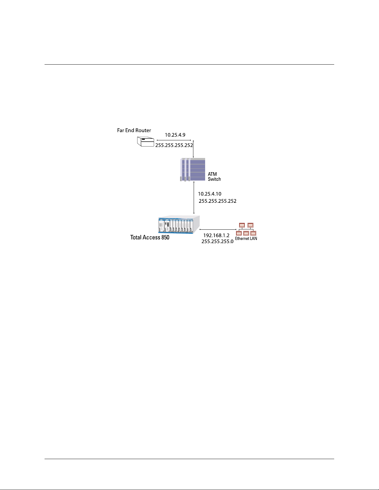
61200375L1-1
TA 850
T1 RCU VoATM UIG/61200376L2-31A
Page 67 of 72
Appendix E. RFC1483 Quick Start (IP Routing)
The TA 850 allows for complete integration of voice and data delivery from one compactplatform (see Figure 20).
Once you have completed the voice turn up procedure from the previous example, adding data tothe circuit requires
some additional setup.
PSU
RCU
BLANK
BLANK
FXS
1
L
6
0
0
5
7
1
1
FXS
1
L
6
7
3
0
0
2
1
FXS
FXS
FXS
1
L
99
0
1175
C
TX
-48V
20 Hz
R
N
3
A
E
3
F
T
TX
A
T
RX
A
M
M
M
O
P
P
N
RX
PWR
T1 ALARM
BANK
T1 TEST
T1 ERROR
ACO
V.35 TD
V.35 RD
ETH LI
ETH TX/RX
BLANK
1175099L1
1
L
08
4
75
11
1175408L1
L1
8
40
5
17
1
1
L
08
4
75
1
1
1
L
08
4
75
1
1
1175099L1
BUSY
BUSY
BUSY
BUSY
BUSY
1
1
1
1
1
2
2
2
2
2
3
3
3
3
3
4
4
4
4
4
Figure 20. Application Diagram
To configure a TA 850 for IP routing, you needto know the VPI and VCI values for thedata circuiton your network.
You also need the IP address of the next hop router in the circuit.
The table on the next page shows how to configure the TA 850 for IP Routing.
© 2001, ADTRAN, Inc. TA 850 User Manual
Page 68

61200375L1-1
TA 850
T1 RCU VoATM UIG/61200376L2-31A
Page 68 of 72
.
IP Routing
Step Action
From the TA 850 main menu, selectthe
1
the ATMnetwork.)
2
Select the
3
Enter the I
4
5
6
ATASCRAMBLING
D
Set
Back allthe wayout to the top level TA 850 menu, and then select the
R
OUTER
menu.
Select C
ONFIGURATION
From the C
and WAN.
ONFIG
ATM C
DLECELLS
ONFIGURATION
format for your network.
menu.
appropriately for your network.
.
menu, you will setup addresses for your LAN
WANmenu. (Hereyou set up
For basicIP routing, use all the default values fromthe
From the
7
configuration.
Enter yourLAN IP
E
menu, enter theIPmenu to enter your LAN
ADDRESS
UBNET MASK
, S
EFAULT GATEWAY
,andD
THERNET
information.
8
For this example,the IP
255.255.255.0, and the D
Arrow back to the main R
WAN
9
menu and then the ATM menu. (Hereyou will enter your data
ADDRESS
EFAULTGATEWAY
OUTERCONFIGURATION
is 192.168.1.2, the
is 10.25.4.10.
S
menu, and select the
PVC information.)
GLOBAL
UBNETMASK
menu.
is
10
11
Create anew PVC by entering themenu. Enter your VPI andVCI
values.
From the
For this example,the
ETMASK
N
RFC1483 IP
menu, enter your LAN information.
F
ARENDIPADDRESS
is 255.255.255.252,and the
is 10.25.4.9, the IP
L
OCALIPADDRESS
is 10.25.4.10.
12 Arrow back to the top level TA 850 menu to activate your changes.
TA 8 50 User Manual © 2001, ADTRAN, Inc.
Page 69

61200375L1-1
TA 850
T1 RCU VoATM UIG/61200376L2-31A
Page 69 of 72
Appendix F. RFC1483 Quick Start (IP Routing with NAT)
To illustrate the use of NAT, consider the example from Appendix C. To set up a single public address that will be
used to access the public network, you will use the
IP Routing with NAT
Step Action
NAT
menu on the
WAN/ATM/RFC1483 IP
menu.
From the
E
1
NABLED
NAT
menu, set
. (This will enable translation and allow you to enter the NAT
ETWORKADDRESSPORTTRANSLATION
N
options.)
IP A
UBLIC
P
Set
2
address. During transmission,private addresses aretranslated into this
DDRESSMODE
S
to
PECIFIED
so you canenteryour public
public (NAPT)address.
You willalso need to set up the Translation Table to do translation on
the body of the packets for certain protocols, such as FTP, to work
correctly.
From the T
3
into the table.
For
4
previously specified publicaddress.
5
For
6
Make sure that
RANSLATIONTABLE
P
UBLICADDRESSMODE
P
ROTOCOL
, selectTCP.
RANSLATEBODY
T
menu, create a new entry by arrowing
, select NAPT A
is set to
DDRESS
Y
ES
.
to usethe
to
© 2001, ADTRAN, Inc. TA 850 User Manual
Page 70

61200375L1-1
TA 850
T1 RCU VoATM UIG/61200376L2-31A
Page 70 of 72
TA 8 50 User Manual © 2001, ADTRAN, Inc.
Page 71

61200375L1-1
TA 850
T1 RCU VoATM UIG/61200376L2-31A
Page 71 of 72
Appendix G. RFC1483 Quick Start (Bridging)
The TA 850 allows for complete integration of voice and data deliveryfrom one compact platform. Once you have
completed the voice turn up procedure from the previousexample, adding data to the circuit requires some additional
setup.
To configure a TA 850 for Bridging, you need to know the V PI and VCI values for the data circuit on your network.
Bridging
Step Action
AN
W
From the TA 850 main menu, selectthe
1
the ATMnetwork.)
menu. (Hereyou set up
10
2
Select the
3
Enter the I
4
Set D
Back allthe wayout to the top level TA 850 menu, and then select the
5
OUTER
R
Enter the
6
From this menu, you will set up addresses for your LAN and WAN.
ATM C
ONFIG
DLECELLS
ATA SCRAMBLING
menu.
C
ONFIGURATION
menu.
format for your network.
appropriately for your network.
menu.
For basicIP routing, use all the default values fromthe
From the E
7
configuration.
Enter yourLAN
8
For this example,the IP
THERNET
menu, enter the IP menu to enteryour LAN
IP
ADDRESS
ADDRESS
S
UBNETMASK
and
is 192.168.1.2 and the
.
is 255.255.255.0.
Arrow back to the main R
WAN
9
menu and then the ATM menu. (Hereyou will enter your data
OUTERCONFIGURATION
menu, and select the
PVC information.)
Create anew PVC by entering themenu. Enter your VPI andVCI
values.
G
LOBAL
S
UBNETMASK
menu.
11
Disable IP on the RFC1483 IP
RIDGE
RFC1483 B
menu. (This enables theTA 850 as a bridge.)
menu andenable Bridging on the
Arrow back to the top level TA 850 menu to activate your changes.
12
All packets that come in on the Ethernet will be forwardedon the WAN.
© 2001, ADTRAN, Inc. TA 850 User Manual
Page 72

61200375L1-1
TA 850
T1 RCU VoATM UIG/61200376L2-31A
Page 72 of 72
TA 8 50 User Manual © 2001, ADTRAN, Inc.
 Loading...