

Page 1

61200659L1-1A
January 2001
MX2800 STS-1
User Manual
4200659L1 AC Non-Redundant Version with Modem
4200659L2 AC Redundant Version with Modem
4200659L3 DC Non-Redundant Version with Modem
4200659L4 DC Redundant Version with Modem
4200659L5 AC Non-Redundant Version
4200659L6 AC Redundant Version
4200659L7 DC Non-Redundant Version
4200659L8 DC Redundant Version
1200291L1 Breakout Panel
4175043L2 Battery Backup
1200657L2 Battery Backup Adapter Cable
1200287L1 Amp to Punch-Down Cable
Page 2

Trademark Information
OpenView is a tradem ark of Hewlet t-Packard Company.
Spectrum is a registered trademark of Cabletron.
901 Explorer Boulevard
P.O. Box 140000
Huntsville, AL 35814-4000
Phone: (256) 963-8000
© 2001 ADTRAN, Inc.
All rights reserved.
Printed in USA.
Page 3

FCC regulations require that the following information be provided in this manual:
1. This equipment complies with Part 68 of FCC rules. On the bottom of the equipment housing is a label showing the FCC registration number and ringer equivalence number (REN). If requested, provide this information to the telephone
company.
2. If this equipment causes harm to the telephone network, the telephone company
may temporarily discontinue service. If possible, advance notification is given;
otherwise, notification is given as soon as possible. The telephone company will
advise the customer of the right to file a complaint with the FCC.
3. The telephone company may make changes in i ts facili ties, equipmen t, operation s,
or procedures that could affect the proper operation of this equipment. Advance
notification and the opportunity to maintain uninterrupted service are given.
4. If experiencing difficult y with thi s equip ment , pleas e conta ct ADTRAN for repai r
and warranty informat ion . The tel ephone company may require this equipment to
be disconnected fro m th e networ k unt il t he p roble m is cor rect ed or it is c erta in the
equipment is not malfunctioning.
5. This unit contains no user-serviceable parts.
6. An FCC compliant telephone cord with a modular plug is provided with this
equipment. This equipmen t i s de si gned to be connected to the telephone network
or premises wiring using an FCC compatible modular jack, which is Part 68 compliant.
7. The following information may be required when applying to the local telephone
company for a dial-up line for the V.34 modem:
Service Type REN FIC USOC
Loop Start 1.6B/0.8A 02LS2 RJ-11C
8. The REN is useful in determining the q uantity o f devices you may conne ct to your
telephone line and s till ha ve a ll of t hose de vices ring whe n your number is c alled .
In most areas, the sum of the RENs of all devices should not exceed five. To be
certain of the number of devices you may connect to your line as determined by
the REN, call your telephone company to determine the maximum REN for your
calling area.
9. This equipment may not be used on coin service provided by the telephone company. Connection to party lines is subject to state tariffs. Contact your state public utility commission or corporation commission for information.
61200659L1-1 MX2800 STS-1 User Manual iii
Page 4
Federal Communications Commission
Radio Frequency Interference Statement
This equipment has been tes te d and f ound t o compl y with the l imit s fo r a Class A digital device, pursuant to Part 15 of th e FCC Rules. The se li mits ar e desig ned to pr ovide
reasonable protection against harmful interference when the equipment is operated in
a commercial environment. This equipment generates, uses, and can radiate radio frequency energy and, if not installed and used in accordance with the instruction manual, may cause harmfu l i nt erf er ence to radio frequencies. Operati on of this equipment
in a residential area is likely to cause harmful interference in which case the user will
be required to correct the interference at his own expense
.
Shielded cables must be used with this unit to ensure compliance with
Class A FCC limits.
Changes or modificat ions t o this unit no t expr ess ly appr oved by
the party responsible for compliance could void the user's
authority to operate the equipment.
Canadian Emissions Requirements
This digital apparatus does not exceed the Class A limits for radio noise emissions
from digital apparatus as set out in the interference-causing equipment standard entitled “Digital Apparatus,” ICES-003 of the Department of Communications.
Cet appareil nuerique respecte les limites de bruits radioelectriques applicables aux
appareils numeriques de Class A prescrites dans la norme sur le materiel brouilleur:
“Appareils Numeriques,” NMB-003 edictee par le ministre des Communications.
iv MX2800 STS-1 User Manual 61200659L1-1
Page 5

Canadian Equipment Limitations
Notice: The Canadian Industry and Science Canada label identifies certified equipment. This certification means that the equipment meets certain telecommunications
network protective, operational, and safety requirements. The Department does not
guarantee the equipment will operate to the user’s satisfaction.
Before installing this equipment, users should ensure that it is permissible to be connected to the facilit ies of the loc al telecommunic ations company. The equipment must
also be installed using an acceptable method of connection. In some cases, the company’s inside wiring associated with a single line individual service may be extended
by means of a cert ifie d conne cto r ass embly (t eleph one ext ensio n co rd). The cust omer
should be aware that compliance with the above limitations may not prevent degradation of serv ice in some situations.
Repairs to certified equipment should be made by an authorized Canadian maintenance facility designated by the supplier. Any repairs or alterations made by the user
to this equipment, or equipment malfunctions, may give the te le communi cat io ns company cause to request the user to disconnect the equipment.
Users should ensure for their own protection that the electrical ground connections of
the power utility, telephone lines and internal met allic water pipe system, if present,
are connected together. This precaution may be particularly important in rural areas.
Users should not attempt to make such connections themselves, but
should contract the appropriate electric inspection authority, or an
electrician, as appropriate.
The Load Number (LN) assigned to each terminal device denotes the percentage of
the total load to be connected to a telephone loop which is used by the device, to prevent overloading. The termination on a loop may consist of any combination of
devices subject only to the requirement that the total of the Load Numbers of all
devices does not exceed 100.
61200659L1-1 MX2800 STS-1 User Manual v
Page 6

Important Safety Instructions
Save These Instructions
When using your telephone eq uipment, please follow th ese basic sa fety preca utions to
reduce the risk of fire, electrical shock, or personal injury:
1. Do not use this product near water, such as near a bathtub, wash bowl, kitchen
sink, laundry tub, in a wet basement, or near a swimming pool.
2. Avoid using a telephone (other than a cordless-type) during an electrical storm.
There is a remote risk of shock from lightning.
3. Do not use the telephone to report a gas leak in the vicinity of the leak.
4. Use only the power cord, power supply, and/or batteries indicated in the manual.
Do not dispose of batteries in a fire. They may explode. Check with local codes
for special disposal instructions.
Warranty and Customer Service
ADTRAN wi ll replace or repair this product within te n years from the date of shipment if it does not meet its published specifications or fails while in service. For
detailed warranty, repair, and return information refer to the ADTRAN Equipment
Warranty and Repair and Return Policy Procedure.
Return Material Authorization (RMA) is required prior to returning equipment to
ADTRAN.
For service, RMA requests, or further information, contact one of the numbers listed
at the end of this manual.
vi MX2800 STS-1 User Manual 61200659L1-1
Page 7

LIMITED PRODUCT WARRANTY
ADTRAN warrants that for ten (10) years from the date of shipment to Customer, all
products manufactured by ADTRAN will be free from defects in materials and workmanship. ADTRAN also warrants that products will conform to the applicable specifications and drawings for such products, as contained in the Product Manual or in
ADTRAN's internal specifi cations and dra wings for such pr oducts (which may o r may
not be reflected in the Produc t Manual). This warran ty only a pplie s if Customer gi ves
ADTRAN written notice of defects during the warranty period. Upon such notice,
ADTRAN will, at its option, either repair or replace the defective item. If ADTRAN
is unable, in a reasonable time, to repair or replace any equipment to a condition as
warranted, Customer is entitled to a full refund of the purchase price upon return of
the equipment to ADTRAN. This warran ty applies only to the original purchas er and
is not transferable without ADTRAN's express written permission. This warranty
becomes null and voi d if Cust omer modi fies or alters the equipment i n an y way, other
than as specifically authorized by ADTRAN.
EXCEPT FOR THE LIMITED WARRANTY DESCRIBED ABOVE, THE FOREGOING CONSTITUTES THE SOLE AND EXCLUSIVE REMEDY OF THE CUSTOMER AND THE EXCLUSIVE LIABILITY OF ADTRAN AND IS IN LIEU OF
ANY AND ALL OTHER WARRANTIES (EXPRESSED OR IMPLIED). ADTRAN
SPECIFICALLY DISCLAIMS ALL OTHER WARRANTIES, INCLUDING (WITHOUT LIMITATION), ALL WARRANTIES OF MERCHANTABILITY AND FITNESS FOR A PARTICULAR PURPOSE. SOME STATES DO NOT ALLOW THE
EXCLUSION OF IMPLIED WARRANTIES, SO THIS EXCLUSION MAY NOT
APPLY TO CUSTOMER.
In no event will ADTRAN or its suppliers be liable to Customer for any incidental,
special, punitive, exemplary or consequential damages experienced by either
Customer or a third party (including, but not limited to, loss of data or information,
loss of profits, or loss of use). ADTRAN is not liable for damages for any cause
whatsoever (whether based in contract, tort, or otherwise) in excess of the amount
paid for the item. Some states do not allow the limitation or exclusion of liability for
incidental or consequential damages, so the above limitation or exclusion may not
apply to Customer.
61200659L1-1 MX2800 STS-1 User Manual vii
Page 8

Customer Service, Product Support Information, and Training
ADTRAN will replace or repair this product within five years from the date of shipment if the product does not meet its published specification, or if it fails while in service.
A return material authorization (RMA) is required prior to returning equipment to
ADTRAN. For service, RMA requests, training, or more information, see the toll-free
contact numbers given below.
Presales Inquiries and Applications Support
Please contact your local distributor, ADTRAN Applications Engineering, or
ADTRAN Sales:
Applications
(800) 615-1176
Engineering
Sales (800) 827-0807
Post-Sale Support
Please contact your lo ca l di st ri but or first. If your local distributor cann ot he lp, please
contact ADTRAN Technical Support and have the unit serial number available.
Technical Support (888) 4ADTRAN
The Custom Extended Services (ACES) program offers multiple types and levels of
service plans which al low you to choose the kind of assistan ce you need. For questions,
call the ACES Help Desk.
ACES Help Desk (888) 874-2237
viii MX2800 STS-1 User Manual 61200659L1-1
Page 9

Repair and Return
If ADTRAN Technical Support determin es th at a repai r is need ed, Tec hni cal Support
will coordinate with the Custom and Product Service (CAPS) department to issue an
RMA number. For information regarding equipment currently in house or possible
fees associated wit h repair, cont act CAPS directly at the following number:Identify the
CAPS Department (256) 963-8722
RMA number clearly on the package (below address), and return to the following address:
ADTRAN Customer and Product Service
6767 Old Madison Pike
Building #6 Suite 690
Huntsville, Alabama 35807
RMA # _____________
Training
The Enterprise Network (EN) Te chni cal Trai ning offers training on our most popular
products. These courses include ov erviews on produc t features a nd functions whi le covering applications of ADTRAN's produc t lines. ADTRAN provides a variety of traini ng
options, including customized tr aining an d courses taught at our faciliti es or at your si te.
For more information about tra ining, please cont act your Territory Manager or the En terprise Training Coordinator.
Training - phone (800) 615-1176, ext. 7500
Training - fax (256) 963 7941
Training - email training@adtran.com
61200659L1-1 MX2800 STS-1 User Manual ix
Page 10

x MX2800 STS-1 User Manual 61200659L1-1
Page 11

Table of Contents
List of Figures........................................................................................................................ xix
List of Tables ......................................................................................................................... xxi
Chapter 1. Introduction
Product Overview ..................................................................................................................1-1
Controller Card 1:1 Redundancy.....................................................................................1-2
STS-1 Overview .......................................................... ..... ...................................................... 1-3
STS-1 Framing...................................................... ..... ......................................................1-3
STS-1 Pointers.................................................................................................................1-3
Transport Overhead (TOH) ............................ ................................................................. 1-4
STS-1 Synchronous Payload Envelope (SPE).............................................................. ...1-4
Virtual Tributaries (VT)................................................................................................... 1-4
Unit Timing......................................................................................................................1-5
SNMP .....................................................................................................................................1-5
Network Manager ........................................................................................................... 1-6
Agent ...............................................................................................................................1-6
MIB ................................................................................................................................. 1-6
Telnet ..................................................................................................................................... 1-6
TL1 ......................................................................................................................................... 1-7
Available Options ................................ ...... ........................................................ .................... 1-8
Breakout Panel (P/N 1200291L1).................................................................................... 1-8
Battery Backup (P/N 4175043L2)...................................................................................1-8
Chapter 2. Installation and Operation
Unpack, Inspect, Power Up ....................................................................................................2-1
Receiving Inspection....................................... ...... ..... ......................................................2-1
ADTRAN Shipments Include.......................................................................................... 2-1
Power Up ...................... ...... ...... .......................................................................................2-2
Rackmount Installation .......................................................................................................... 2-5
Connecting the Breakout Panel........................................................................................ 2-6
Rear Panel ..............................................................................................................................2-7
LAN Port..........................................................................................................................2-8
Modem Port ..................................................................................................................... 2-8
Noncritical and Critical Alarm Connectors ................................................. ...... ...... ........ 2-8
Network Interfaces........................................................................................................... 2-9
DSX-1/E1 Interfaces........................................................................................................2-9
Power Connection.......................... ...... ..... ................................................... ...... ...... ........ 2-9
Front Panel ...........................................................................................................................2-10
61200659L1-1 MX2800 STS-1 User Manual xi
Page 12

Table of Contents
Craft Port........................................................................................................................2-10
Establishing Terminal Connection ............................................. ...... ......................2-10
Navigating Within the Menus ................................................................................2-11
Status ..............................................................................................................2-12
Statistics ..........................................................................................................2-12
Configuration .................................................................................................. 2-12
Diagnostics .....................................................................................................2-12
Logout ............................................................................................................. 2-12
ACO Buttons........................ ...... ...... ..............................................................................2-12
LED Descriptions...........................................................................................................2-13
Power Supply A/B .................................................................................................2-13
Status LEDs ...........................................................................................................2-13
T1/E1 Status LEDs ................................................................................................2-15
Chapter 3. Configuration
Network Interface ...................................................................................................................3-3
STS-1 Configuration.............................................. ...... ................................................... .3-3
Line Length .............................................................................................................. 3-3
Timing ...................................................................................................................... 3-3
XCV Threshold ........................................................................................................3-4
VT Mode ..................................................................................................................3-5
Protection Configuration..................................................................................................3-5
Active Controller .....................................................................................................3-5
Network Protection ..................................................................................................3-6
Max. Switch Threshold ............................................................................................3-6
Min. Switching Period .............................................................................................3-6
Miscellaneous...................................................................................................................3-6
Loopback Timeout ...................................................................................................3-6
External Clock Configuration ..................................................................................3-7
VT Interface ...........................................................................................................................3 -7
VT Interface #1-28...........................................................................................................3-8
VT/Port Mapping .....................................................................................................3-8
T1 State ....................................................................................................................3-8
T1 Coding ................................................................................................................3-8
T1 Line Length ........................................................................................................3-9
T1 Remote Loopback ...............................................................................................3 -9
T1 Circuit Protection ...............................................................................................3-9
Hairpin Loopback ....................................................................................................3-9
Line ID .....................................................................................................................3-9
Set Multiple......................................................................................................................3-9
Set Cross-Connect Mapping ..........................................................................................3-10
xii MX2800 STS-1 User Manual 61200659L1-1
Page 13

Table of Contents
Restore Defaults .....................................................................................................3-11
Restore VT Mapping Defaults....................................................................................... 3-11
Protection Threshold (1-28)...........................................................................................3-11
XCV Threshold..............................................................................................................3-12
System Management ............................................................................................................ 3-13
Management Options...................................... ...... ..... ....................................................3-14
Local IP Address ....................................................................................................3-14
Gateway IP Address ..............................................................................................3 -14
Subnet Mask .......................................................................................................... 3-14
Management Port ........................................................... ..... ...................................3-14
Dialup Options .......................................................................................................3-14
Primary and Secondary Phone Numbers ........................................................ 3-15
Initializing String ............................................................................................3-15
Dial String ......................................................................................................3-15
Maximum Redial Attempts ............................................................................3-15
Idle Timeout ................................................................................................... 3-16
Connection Timeout .......................................................................................3-16
Pause Between Calls ....................................................................................... 3-16
Dialout On Trap ..............................................................................................3-16
Answer on Ring ..............................................................................................3-16
Modem Mode .................................................................................................3-17
Modem Baud Rate ..........................................................................................3-17
Hangup ...........................................................................................................3-17
Last Modem Response ...................................................................................3-17
Alarm Relays ............................................................. ....................................................3-18
Alarm Relay Configuration ................................................ ...... ...... ....................... 3-18
STS-1 Alarms .................................................................................................3 -19
VT/Port Alarms .............................................................................................. 3-21
System Alarms ................................................................................................ 3-23
Power Supply Alarms .............................................................. ..... ...... ............ 3-24
SNMP Management Options............................................................ ...... ....................... 3-25
Trap IP Addresses .................................................................................................. 3-25
Trap Generation ..................................................................................................... 3-25
STS-1 Active Alarm Traps ............................................................................. 3-26
STS-1 Standby Alarm Traps ..........................................................................3-28
VT/Port Traps ................................................................................................. 3-30
System Traps .................................................................................................. 3-31
Power Supply Alarm Traps ............................................................................ 3-33
MIB II Standard Alarm Traps ........................................................................3 -34
Read Community Name ........................................................................................3-34
Write Community Name ........................................................................................ 3-34
61200659L1-1 MX2800 STS-1 User Manual xiii
Page 14

Table of Contents
Trap Community Name .........................................................................................3-34
System Security..............................................................................................................3-35
Password ................................................................................................................3-35
Terminal Timeout ..................................................................................................3-35
IP Security ..............................................................................................................3-35
IP Hosts ..................................................................................................................3-35
Date & Time...................................................................................................................3-35
Miscellaneous.................................................................................................................3-36
Equipment Identification .......................................................................................3-36
Unit ID ............................................................................................................3-36
STS-1 J1 Path Trace .......................................................................................3-36
Syslog Setup ............................ ..... ................................................... ...... ..... ...........3-36
Transmission ...................................................................................................3-36
Host IP Address ..............................................................................................3-36
Severity Level .................................................................................................3-36
Host Facility ...................................................................................................3-37
TL1 Account Management ....................................................................................3-37
Save on Logout ......................................................................................................3-38
Craft baud rate .......................................................................................................3-38
Utilities .................................................................................................................................3-38
Load Default Settings.....................................................................................................3-40
Update FLASH Software...............................................................................................3-40
Update Via XMODEM ..........................................................................................3-40
Update via TFTP Server ........................................................................................3-41
Config Transfer..............................................................................................................3-41
Saving to a TFTP Server ........................................................................................3-41
Retrieving from a TFTP Server .............................................................................3-42
System Reset..................................................................................................................3-43
Save Configuration ...............................................................................................................3-43
Chapter 4. Status
STS-1 State ........................................................ ..... ...... ...... .................................................... 4-2
Card A..............................................................................................................................4-2
Card A/Card B Alarms.....................................................................................................4-2
Network Port Mapping.....................................................................................................4 -4
Power Supply State ................................................................................................................4-5
System State ...........................................................................................................................4-5
Alarm ...............................................................................................................................4-5
Card A/Card B ................................................................................................................. 4-6
Protection .........................................................................................................................4-7
Card Comm......................................................................................................................4-7
xiv MX2800 STS-1 User Manual 61200659L1-1
Page 15

Table of Contents
Timing Status .........................................................................................................................4-8
Clock Status.....................................................................................................................4-8
Current Source................................................................................................................. 4-8
PRI Ext. Clock................................................................................................................. 4-9
SEC Ext. Clock................................................................................................................ 4-9
VT/Port State ........................................................................................................................4-10
VT/Port State ................................................................................................................4-10
Acknowledge Alarms (ACO) ............................................................................................... 4-12
Chapter 5. Statistics
STS-1 Statistics ............................... .......................................................................................5-2
24 Hour Alarm History.................................................................................................... 5-2
Performance Parameters.................................................................................................. 5-6
Interval starting at: ...................................................................................................5-7
Severely Errored Framing Seconds (SEFS) ............................................................ 5-7
Section Coding Violations (SCV) ................................................................... ..... ...5-7
Line Coding Violations (LCV) ................................................................................5-7
Path Coding Violations (PCV) ................................................................................5-7
Section Errored Seconds (SES) ............................................................................... 5-8
Line Errored Seconds (LES) .................................................................................... 5-8
Path Errored Seconds (PES) ....................................................................................5-8
Section Severely Errored Seconds (SSES) .............................................................. 5-8
Line Severely Errored Seconds (LSES) .................................................................. 5-8
Path Severely Errored Seconds (PSES) ................................................................... 5-8
Line Unavailable Seconds (LUAS) ......................................................................... 5-9
Path Unavailable Seconds (PUAS) ..........................................................................5-9
Clear All Local STS-1 Statistics ..............................................................................5-9
Local VT Statistics ................................................................................................................. 5-9
Alarm History........................................... ...... ...... ......................................................... 5-10
Performance Parameters................................................................................................ 5-12
Local Port Statistics .............................................................................................................5-15
Loss of Signal Alarms ................................................................................................... 5-15
Bipolar Violation Counts ...................................................... ........................................5-15
AIS Loop Alarms .......................................................................................................... 5-15
AIS Carrier Alarms ....................................................................................................... 5-16
Far End STS-1 Statistics ...................................................................................................... 5-16
Performance Parameters................................................................................................ 5-16
Interval starting at: .................................................................................................5 -18
Severely Errored Framing Seconds (SEFS) .......................................................... 5-18
Section Coding Violations (SCV) ................................................................... ..... .5-18
Line Coding Violations (LCV) ..............................................................................5-18
61200659L1-1 MX2800 STS-1 User Manual xv
Page 16

Table of Contents
Path Coding Violations (PCV) ..............................................................................5-18
Section Errored Seconds (SES) .............................................................................5-19
Line Errored Seconds (LES) ..................................................................................5-19
Path Errored Seconds (PES) ..................................................................................5-19
Section Severely Errored Seconds (SSES) ............................................................5-19
Line Severely Errored Seconds (LSES) .................................................................5-19
Path Severely Errored Seconds (PSES) .................................................................5-19
Line Unavailable Seconds (LUAS) .......................................................................5-20
Path Unavailable Seconds (PUAS) ........................................................................5-20
Clear All Far End STS-1 Statistics ........................................................................5-20
Chapter 6. Diagnostics
VT/Port Loopbacks ................................................................................................................6-2
Tributary...........................................................................................................................6-2
Analog Network...............................................................................................................6-3
Digital Line/Net ...............................................................................................................6-4
Codec Line/Net................................................................................................................6-4
CSU Loopback.................................................................................................................6-5
CSU Loopback w/BERT..................................................................................................6-5
VT BERT.........................................................................................................................6-6
Line BERT.......................................................................................................................6-7
STS-1 Loopbacks ............................. ...... .................................................. ...... ...... ..................6-8
Line Network ...................................................................................................................6-8
Analog Loopback.............................................................................................................6-9
Digital Loopback............................................................................................................6-10
Metallic Diagnostics ......................................................................................................6-11
Chapter 7. Circuit and Network Redundancy
Non-Redundant Mode ............................................................................................................7-2
Circuit Failure Recovery Mode ..............................................................................................7-3
Circuit and Network Failure Recovery Mode ........................................................................7-4
Chapter 8. Power Loss Recovery
Non-Redundant Power Mode ................................................................................................. 8 -2
Power Supply Recovery Mode ...............................................................................................8-3
Power Supply and Source Recovery Mode ........................................................................... .8-4
Battery Backup Mode .............................................................................................................8-5
Chapter 9. Transaction Language 1 (TL1)
Introduction ............................................................................................................................9-1
Overview ................................................................................................................................9-1
xvi MX 2800 STS-1 User Manual 61200659L1-1
Page 17

Table of Contents
TL1 Messages ........................................................................................................................9-2
TL1 Responses................................................................................................................. 9-2
Acknowledgment Messages ....................................................................................9-2
In Progress ........................................................................................................ 9-3
All Right ...........................................................................................................9-3
Output Response Messages .....................................................................................9-3
Autonomous Messages ............................................................................................9-4
TL1 Commands ......................................................................................................................9-5
TL1 Autonomous Messages .................................................................................................9-10
TL1 Error Codes .................................................................................................................. 9-13
Appendix A. Pinouts .......................................................................................................... A-1
Appendix B. Specifications Summary............................................................................... B-1
Appendix C. Acronyms/Abbreviations ............................................................................ C-1
Appendix D. Glossary........................................................................................................ D-1
Index ..............................................................................................................................Index-1
61200659L1-1 MX2800 STS-1 User Manual xvii
Page 18

Table of Contents
xviii MX2800 STS-1 User Manual 61200659L1-1
Page 19

List of Figures
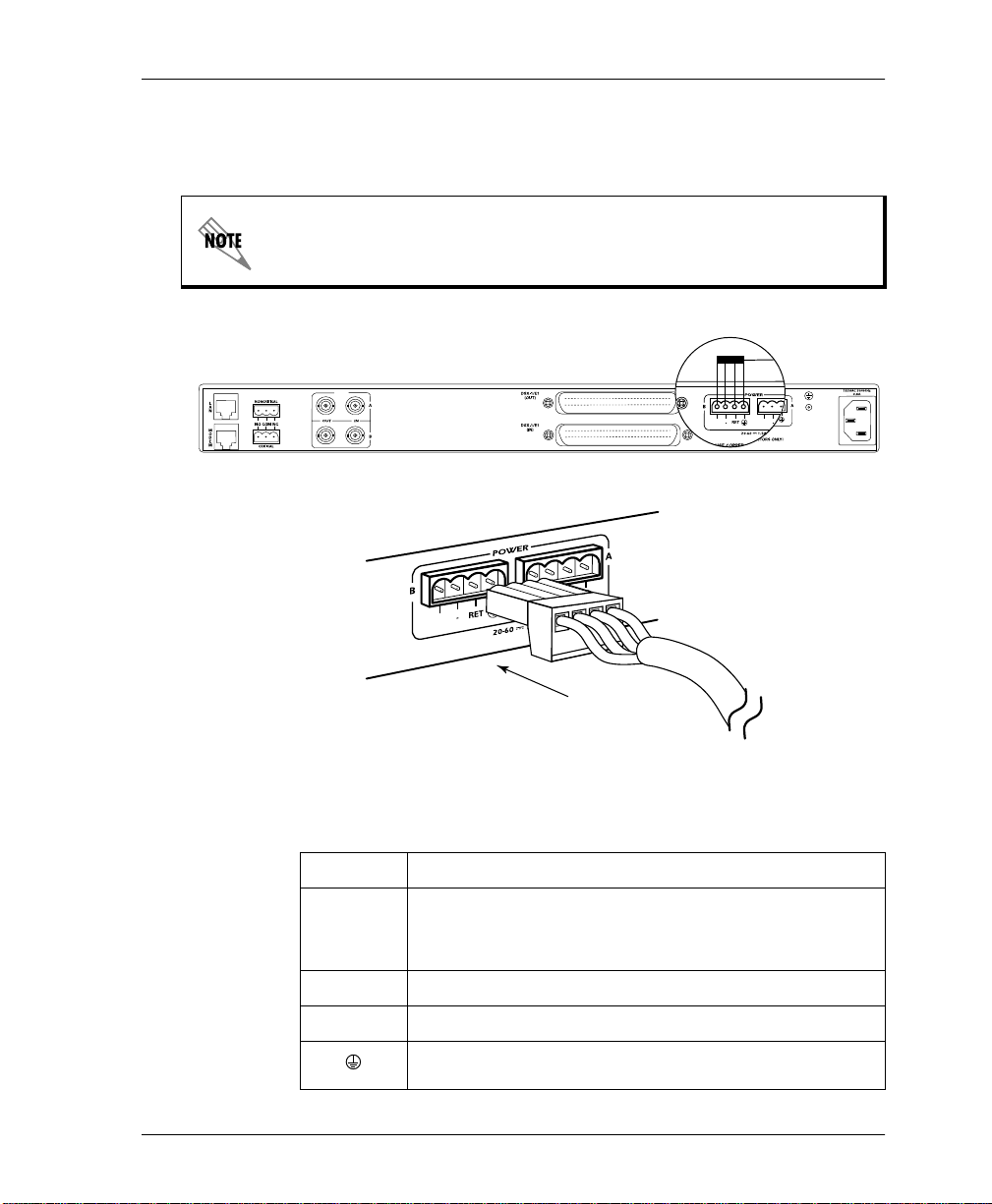
Figure 2-1. DC Power Connector.........................................................................................2-3
Figure 2-2. The Breakout Panel ...........................................................................................2-6
Figure 2-3. MX2800 STS-1 Rear View ...............................................................................2-7
Figure 2-4. MX2800 STS-1 Front Panel............................................................................2-10
Figure 2-5. Terminal Main Menu ....................................................................................... 2-11
Figure 3-1. Configuration Menu ..........................................................................................3-1
Figure 3-2. Configuration Menu Tree..................................................................................3-2
Figure 3-3. Network Configuration Menu ........................................................................... 3-3
Figure 3-4. VT Interface Menu ............................................................................................3-7
Figure 3-5. Configure VT Interface #1 Menu...................................................................... 3-8
Figure 3-6. Set Multiple Menu...........................................................................................3-10
Figure 3-7. Set Cross-Connect Mapping Menu .................................................................3-11
Figure 3-8. XCV Threshold Menu.....................................................................................3-12
Figure 3-9. System Management Configuration Menu...................................................... 3-13
Figure 3-10. Dialup Options Menu......................................................................................3-15
Figure 3-11. Alarm Relay Configuration Menu..................................................................3-18
Figure 3-12. Trap Generation Menu.....................................................................................3-25
Figure 3-13. System Utilities Menu.....................................................................................3-39
Figure 4-1. Status Menu....................................................................................................... 4-1
Figure 5-1. Statistics Menu .................................................................................................. 5-1
Figure 5-2. Local STS-1 Statistics Menu.............................................................................5-2
Figure 5-3. Local STS-1 Current Alarm Count Screen........................................................ 5-4
Figure 5-4. Local STS-1 24-Hour Alarm History Screen....................................................5-5
Figure 5-5. Local STS-1 Performance Parameters (Current 15 Minutes)............................ 5-6
Figure 5-6. Local STS-1 Performance Parameters (24 Hour History)................................. 5-6
Figure 5-7. Local STS-1 Performance Parameters (24 Hour Totals)...................................5-7
Figure 5-8. Local VT Statistics ............................................................................................5-9
Figure 5-9. Local VT-LOP Alarm Count Screen (Current 15 Minutes)............................5-12
Figure 5-10. Local VT-LOP Alarm Count Screen (24 Hour History).................................5-12
Figure 5-11. Local VT-CV Performance Parameters (Current 15 Minutes)........................5-14
Figure 5-12. Local VT-CV Performance Parameters (24 Hour History).............................5-14
Figure 5-13. Local Port Statistics Menu............................................................................... 5-15
Page 20

List of Figures
Figure 5-14. Far End STS-1 Statistics Menu .......................................................................5-16
Figure 5-15. Far End STS-1 Performance Parameters (Current 15 Minutes)......................5-17
Figure 5-16. Far End STS-1 Performance Parameters (24 Hour History)...........................5-17
Figure 5-17. Far End STS-1 Performance Parameters (24 Hour Totals) .............................5-18
Figure 6-1. Diagnostics Menu..............................................................................................6-1
Figure 6-2. VT/Port Diagnostics Menu................................................................................6 -2
Figure 6-3. Tributary Loopback Test....................................................................................6-3
Figure 6-4. Analog Network Loopback................................................................................6-3
Figure 6-5. Digital Line/Network Loopback........................................................................6-4
Figure 6-6. Codec Loopback................................................................................................6-4
Figure 6-7. Diagnostics Menu with BERT Selected ............................................................6-6
Figure 6-8. VT Bert Test ......................................................................................................6-7
Figure 6-9. Line Bert Test ....................................................................................................6-7
Figure 6-10. STS-1 Diagnostics Menu...................................................................................6-8
Figure 6-11. Line Network Test .............................................................................................6-9
Figure 6-12. Analog Loopback...............................................................................................6-9
Figure 6-13. Digital Loopback.............................................................................................6-10
Figure 6-14. Metallic Diagnostics Loopback Test ............................................................... 6-11
Figure 7-1. Non-Redundant Mode .......................................................................................7-2
Figure 7-2. Circuit Failure Recovery Mode .........................................................................7-3
Figure 7-3. Circuit and Network Failure Recovery Mode ...................................................7-5
Figure 8-1. Non-Redundant Power Mode............................................................................8-2
Figure 8-2. Power Supply Failure Recovery Mode..............................................................8-3
Figure 8-3. Power Supply and Source Failure Recovery Mode...........................................8-4
Figure 8-4. Battery Backup System......................................................................................8-5
xx MX2800 ST S-1 User Manual 61200659L1-1
Page 21

List of Tables
Table 2-1. DC Connector Symbol Definitions ................................................................... 2-3
Table 2-2. LED Conditions for Active Cards ..................................................................2-14
Table 2-3. LED Conditions for Standby Cards.................................................................2-15
Table 2-4. T1/E1 LED Conditions ...................................................................................2-16
Table 3-1. Syslog Severity Levels ..................................................................................3-37
Table 7-1. Configuration Requirements for Circuit Recovery ...........................................7-4
Table 9-1. TL1 Commands ................................................................................................ 9-6
Table 9-2. MX2800 STS-1 Alarm Events ....................................................................... 9-10
Table 9-3. MX2800 STS-1 Informational Events ............................................................ 9-12
Table 9-4. TL1 Error Codes..............................................................................................9-13
Table A-1. Craft Port Pin Assignments.............................................................................. A-1
Table A-2. LAN Port Pin Assignments ............................................................................. A-2
Table A-3. Modem Port Pin Assignments.......................................................................... A-2
Table A-4. Amp Pin Assignments...................................................................................... A-3
61200659L1-1 MX2800 STS-1 User Manual xxi
Page 22

List of Tables
xxii MX2800 STS-1 User Manual 61200659L1-1
Page 23

Chapter 1
Introduction
PRODUCT OVERVIEW
The MX2800 STS-1 is a SONET multiplexer that consolidates T1
and E1 signals into an STS-1 signal. This unit provides a costeffective , ver sat il e t ool for combining independent T1s or E1s ove r
the same STS-1 carrier.
Embedded SNMP (simple network management protocol) and
Telnet are available through the modem port using SLIP/PPP or
through the 10BaseT ethernet port. Using the Management
Information Base II (MIB II), RFC 1595 standards, and an
ADTRAN enterprise MIB, the MX2800 STS-1 can be configured,
monitored, and diagnosed with standard SNMP network
management programs such as Hewlett Packard’s HP OpenView™
and Cabletron’ s Spe ctrum™. In addi tion, the SysL og Host Daemon
allows remote monitoring, collecting, and logging of MX2800
STS-1 events in real time. This information can be useful during
installation setups and/or troubleshooting.
Complete configuration, diagnostics, and performance monitoring
are available through SNMP, Telnet, or a VT-100 terminal
interface. This connection can be made via ethernet, a local EIA232 link, or through the built-in V.34 modem (see the note at the
end of this section on page 1-2). The modem can di al-ou t a “cry for
help” for units located in unmanned facilities. The MX2800 STS-1
is designed for either desktop use or for installation in a 19-inch or
23-inch rack.
61200659L1-1 MX2800 STS-1 User Manual 1-1
Page 24
Chapter 1. Introduction
The major features of the MX2800 STS-1 are as follows:
• Built-in 1:1 redundancy
• Hot-swappable controller cards
• Independent, dual-load sharing, redundant power supplies
• Embedded SNMP and Telnet management through 10BaseT
ethernet or SLIP/PPP dialup
• Detailed performance monitoring for local and remote units
• Simplified configuration through the VT-100 terminal menu
structure
• Integrated V.34 modem for dial-up and dial-out access (see the
following note)
• Capable of backhauling multiple service types (T1/E1)
• AC or DC power
• VT Hairpining
• VT cross-connect to any DS1
• NEBS Level 3 compliant
• Standard 10-year warranty
Information regardi ng the built- in modem applies to t he following
list of part numbers: 4200659L1, L2, L3, and L4.
Controller Card 1:1 Redundancy
The MX2800 STS-1 supports two hot-swappable controller cards
which provide 1:1 red undancy f or the T1 and STS-1 signal s as wel l
as the STS-1 connections. With two cards installed, the MX2800
STS-1 can recover from circuit or network failure, depending on
the configuration. See Chapter 7, Circuit and Networ k Redundancy
for more information.
1-2 MX2800 STS-1 User Manual 61200659L1-1
Page 25

STS-1 OVERVIEW
The MX2800 STS-1 multiplexer del ivers up to 28 T1s or 21 E1s via
the SONET Synchronous Transport Signal Level One (STS-1) at a
speed of 51.84 Mbps. This is a cost-effective way to provide T1/E1
signals without the need for costly and complex multi-level
multiplexin g/demultiplexing as in an M13 multiplexer. The T1/E1
signals can be directly multiplexed into the SONET STS-1 signal,
allowing simplified add and drop functionality.
The MX2800 STS-1 multiplexer also implements VT hairpining
and VT cross-connect mapping. Any VT can be hai rp inn ed bac k to
the STS-1 signal for dropping further down the SONET ring.
Cross-connect mapping per mits a VT to be mapped to any of the 28
available physical ports.
STS-1 Framing
The STS-1 frame is organized as 9 rows by 90 columns of bytes.
This frame is transmitted row by row, from left to right, and with
the most significant bit (MSB) of each byte transmitted first. It is
defined to operate at the basic rate of 8 kHz or 125 microseconds
per frame, or 8,000 frames per second at a bit rate of 51.84 Mbps.
Chapter 1. Introduction
The frame is divided into two parts to physically segregate the
layers. The first 3 columns make up the transport overhead (TOH);
the remainder is the synchronous payload envelope (SPE). The
TOH has 3 rows for the s ect io n over hea d (SOH) and 6 rows for the
line overhead (LOH). The SPE has one column for the path
overhead (POH). The remaining 86 columns are for payload data
(49.536 Mbps).
STS-1 Pointers
There are several mechan isms that allow for timing compensation
between the STS-1 and its low speed tributaries. The MX2800
STS-1 multiplexer uses pointer adjustments to achieve timing
61200659L1-1 MX2800 STS-1 User Manual 1-3
Page 26

Chapter 1. Introduction
compensation. Pointer adjustments allow the synchronous payload
envelope (SPE) to float with respect to the SONET frame. The
pointer is contained in the H1 and H2 bytes of the line overhead
(LOH), and is a count of the number of bytes the J1 byte is away
from the H3 byte, not including the transport overhead. When
timing differences exist, dummy bytes are inserted into the SPE
without affecting data. The receiving end can recover the payload
since the pointer is adjus ted t o indi cate where t he pay load o ver head
(POH) starts.
Transport Overhead (TOH)
The first three columns are the TOH, which contains the overhead
bytes for the Section and Line layers. Section overhead is
comprised of 9 bytes and Line overhead is comprised of 18 bytes.
STS-1 Synchronous Payload Envelope (SPE)
The SPE has 87 columns and 9 rows of bytes for a total of 783
bytes. Column 1 contains the STS Path Overhead and has 9 bytes.
The remaining 774 bytes are available for payload.
Virtual Tributaries (VT)
The SPE is divided into seven virtual tributary groups, made up of
12 columns each. Smaller tributaries are multiplexed together to
form these groups. For exa mple, th ere can be f our VT1.5 tri butaries
in a VT group or three VT2 tributaries. A VT1.5 tributary consists
of three column s per STS-1 frame and has a bit r at e of 1.728 Mbps,
allowing transport of a T1 at 1.544 Mbps plus requir ed ove rhead. A
VT2 uses four columns per STS-1 fr ame and has a bi t rat e of 2.304
Mbps, allowing transport of an E1 at 2.048 Mbps plus required
overhead.
1-4 MX2800 STS-1 User Manual 61200659L1-1
Page 27

Unit Timing
Chapter 1. Introduction
The MX2800 STS-1 multiplexer allows three timing methods. The
OOP
first is
L
timed, in which the multiplexer derives timing from
the incomin g STS-1 signal. A failure in this signal, such as a lossof-signal (LOS) or a loss-of-framing (LOF) will cause the unit to
OLDOVER
H
enter
defect. During
(HO)
mode for the duration of the receive signal
HO
, the unit wi ll continue tr ansmitting at the same
rate as the receive signal prior to entering its defect condition.
Stability of the transmit du ring
over 24 hours. The defect condition must be cleared before
HO
is guaranteed to +/- 4.9 ppm
L
OOP
time mode can be resumed.
The second mode of operation is
F
(FR)
mode. In this
REE-RUNNING
mode, an internal oscillator is used to generate transmit timing.
REE-RUNNING
F
mode provides a SONET minimum clock
specification of +/- 20 ppm.
The third timing operation mode is
XTERNAL
E
XTERNAL
E
.
timing
mode allows the MX2800 STS-1 to derive its transmit timing from
any one of the 28 DSX-1/E1 physical ports. Th e ports s elect ed may
be data carrying ports. Two sources can be specified to provide
external timing: a primary and a secondary source. Failure of the
primary source (due to LOS or AIS) will cause the unit to swi tch to
the secondary s ource, i f availabl e. In t he event that both the primary
OLDOVER
and secondary sources are lost, the unit will enter
H
mode
as described previously. Holdover mode will be exited upon
recovery of at least one clock source.
SNMP
The MX2800 STS-1's embedded SNMP feature allows the unit to
be accessed and controlled by a network manager through the
10BaseT local area network (LAN) port. The MX2800 STS-1
61200659L1-1 MX2800 STS-1 User Manual 1-5
Page 28
Chapter 1. Introduction
supports the MIB-II standard, RFC 1213, RFC 1595, and the
ADTRAN Enterprise Specific MIB.
MIB files are available at
www.adtran.com
.
The term SNMP broadly refers to the message protocols used to
exchange information between the network management system
(NMS) and the managed devices, as well as to the structure of
device management databases. SNMP has three basic components,
the network manager, the agent, and the MIB.
Network Manager
The network manager is a set of control programs that collect,
control, and present data pertinent to the operation of the network
devices. These programs reside on a network management station.
Agent
The agent is a c ontrol p rogram tha t resi des in ev ery ne twork devi ce.
This program responds to quer ie s an d commands fr om the netwo rk
manager, returns requested information or invokes configuration
changes initiated by the manager, and sends unso li ci te d tr aps to the
manager.
MIB
A MIB is an industry standard presentation of all status and
configuration parameters supported by a network device.
TELNET
Telnet provides a password-protected, remote login facility to the
MX2800 STS-1 that allows a remote user to control the MX2800
STS-1 through the te rminal men us. Only one Telnet session may be
active at a time.
1-6 MX2800 STS-1 User Manual 61200659L1-1
Page 29

TL1
Chapter 1. Introduction
Transaction Language 1 (TL1) is an ASCII based language that
supports both command-response and autonomous (NE) message
generation. Commonly, TL1 is used over a X.25 packet network
but is completely independent of any physical layer protocols. For
the MX2800 STS-1, TL1 is implemented as a Telnet session
running over either Ethernet or PPP. Only one TL1 Telnet
connection can be active at a time.
61200659L1-1 MX2800 STS-1 User Manual 1-7
Page 30

Chapter 1. Introduction
AVAILABLE OPTIONS
The following optional equip men t is ava il abl e for use wit h th e
MX2800 STS-1. Contact your local distributor or the ADTRAN
sales department for more information (see front section of this
manual for phone number).
Breakout Panel (P/N 1200291L1)
The optional breakout panel connects to the MX2800 STS-1 and
provides 28 RJ connectors for the individual T1s/E1s. Shipment
includes two six-foot, 64-pin to 64-pin Amp cables which allow
direct cabling to the MX2800 STS-1 (see Connecting the Breakout
Panel on page 2-6 for more information).
Battery Backup (P/N 4175043L2)
The battery backup system provides power backup in the event of
power loss. This system includes the battery, an AC battery
charger, and an alarm cable.
1-8 MX2800 STS-1 User Manual 61200659L1-1
Page 31

Chapter 2
Installation and Operation
UNPACK, INSPECT, POWER UP
Receiving Inspection
Carefully inspect the MX2800 STS-1 for any damage that might
have occurred in shipment. If damage is suspected, file a claim
immediately with the carrier and contact ADTRAN Technical
Support (see the front section of this manual for phone numbers).
Keep the original shipping container to use for future shipment or
verification of damage during shipment.
ADTRAN Shipments Include
The following items are included in shipments of the MX2800
STS-1:
• MX2800 STS-1 unit
• DC or AC power supply (two power supplies come with the
Redundant versions)
• Controller card (two cards come with the Redundant versions)
• 8-pin to 6-pin modular cable (Modem version only)
• 8-pin to 8-pin modular cable
• 8-pin modular to DB-9 female connector
• Two 4-position terminal lug connectors
• 3-position terminal lug connector
61200659L1-1 MX2800 User Manual 2-1
Page 32

Chapter 2. Installation and Operation
• Six-foot AC power cord (AC Versions only)
• Mounting ears and screws for 19-inch or 23-inch rack
installation
• User Manual or CD containing the User Manual
Power Up
The ADTRAN MX2800 STS-1 MIB is available at
www.adtran.com
.
The AC version of the MX2800 STS-1 is provided with a six-foot
power cord, terminated by a three-prong plug which conne ct s to a
grounded 120 VAC power receptacle.
Power to the AC version of the MX2800 STS-1 must be provi ded fr om
a grounded 120 VAC, 60 Hz receptacle.
The DC version of the MX2800 STS-1 is provided with two
4-position modular terminal lug connectors. These connectors
make it easier to perform initial wiring and to connect and
disconnect DC power when replacing rackmount units.
For more detailed information on power connections, refer to
Chapter 8, Power Loss Recovery.
Once the modular connector is wired, push it firmly into one of the
rear panel
2-2 MX2800 User Manual 61200659L1-1
POWER
connectors. Figure 2-1 and Table 2-1 on page
Page 33
Chapter 2. Installation and Operation
2-3 illustrate the DC power connector and give definitions for the
four connector symbols.
The chassis should be connected to an earth ground using the
ground stud locat ed between th e AC and DC power sources on the
rear panel.
NET
PWR
PWR
FAIL
FAIL
PWR
FAIL
Figure 2-1. DC Power Connector
Table 2-1. DC Connector Symbol Definitions
Symbol Definition
Battery backup connection. If AC fails, a trap is sent to
PWR FAIL
alert user when connected to the 4175043L2 battery
backup system or equivalent
- Negative side of DC power source (usually -48V)
RET Positive side of DC power source (usually ground)
Frame Ground
61200659L1-1 MX2800 User Manual 2-3
Page 34

Chapter 2. Installation and Operation
The following UL requirements must be met during installation of
the MX2800 STS-1 DC version:
1. Disconnect all power sources prior to servicing (unit may use
multiple power sources).
2. Input: Minimum 48 VDC, 0.8 A
3. Connect to a reliably grounded -48 VDC source which is
electrically isolated from the AC source.
4. The branch circuit overcurrent protection shall be a fuse or
circuit breaker rated minimum 48 VDC, maximum 20 A.
5. A readily accessible disconnect device that is suitab ly approved
and rated, shall be incorporated in the field wiring.
6. The chassis should be connected to an earth ground using the
ground stud located between the AC and DC power sources on
the rear panel.
7. The unit shall be installed in accordance with the requirements
of NEC NFPA 70.
Minimum 120 VAC, 0.32 A
8. The unit shall be installed in accordance with Arti cles 400 and
364.8 of the National Electrical Code NFPA 70 when installed
outside of a Restricted Access Location (i.e. Central Office,
behind a locked door, or service personnel area only).
9. Care should be taken not t o upset the stability of the e qui pment
rack after installation is complete.
To meet the UL requirements during installation, use copper
conductors only.
2-4 MX2800 User Manual 61200659L1-1
Page 35

RACKMOUNT INSTALLATION
The MX2800 STS-1 can be mounted into a standard 19-inch or
23-inch equipment rack. Follow these steps to mount your unit into
a rack:
1. Prepare the MX2800 STS-1 mounting ears by scraping the
paint away from the mounting ears’ portion that makes contact
with the rack and the portion where the screw mounts into the
side of the MX2800 STS-1.
2. Install the mounting flanges on each side of the MX2800 STS- 1
at one of the three available positions.
Be sure to install the flanges with the screws provided.
3. After the flanges have been installed, position the MX2800
STS-1 at the correct location within the rack and secure the
mounting flanges to the mounting rails of the rack.
Chapter 2. Installation and Operation
4. Make all network, DTE, and power connections to the rear of
the unit. See Power Up on page 2-2 for more information on
making the DC power connection.
5. Using the 8-position modular to DB- 9 female connec tor and th e
8-position modular to 8-position modular cable, connect a
VT 100 terminal device to t he
CRAFT
port on the front panel of
the unit.
Two MX2800 STS-1s may be stacked with no spacing between units.
ADTRAN recommends 1U (1.75") of separation above and below the
two stacked units. This spacing allows the unit to dissipate heat. The
design of the MX2800 STS-1 uses the chassis to distribute heat
generated by the unit's internal cards. This design allows the unit to
operate without a cooling fan, which increases its overall reliability.
61200659L1-1 MX2800 User Manual 2-5
Page 36

Chapter 2. Installation and Operation
Connecting the Breakout Panel
The optional breakout panel (P/N 1200291L1) connects to the
MX2800 STS-1 via the
IN
and
the back of the unit, and provides 28 RJ connectors for the
individual T1s/E1s. Shipment includes two six-foot, 64-pin to
64-pin Amp cables which allow direct cabling to the
MX2800 STS-1. Connect the break out pane l’s
to the MX2800 STS-1’s
panel’s
OUT
Champ connector to the MX2800 STS- 1’s
IN
Champ connector and the breakout
connector (see Figure 2-2).
Front View
2 4 6 8 10 12 14 16 18 20 22 24 26 28
1 3 5 7 9 11 13 15 17 19 21 23 25 27
N
A
P
A
E
L
R
C
T
M
F
T
OUT
Champ connectors located on
IN
Champ connector
OUT
Champ
Rear View
IN OUT
NONCRITICAL
L
A
N
NO COM NC
M
O
D
E
M
CRITICAL
NET
A
OUT
IN
B
Cable 1
DSX-1/E1
(OUT)
DSX-1/E1
(IN)
DC POWER
PWR
PWR
RET
RET
FAIL
FAIL
AB
Figure 2-2. The Breakout Panel
2-6 MX2800 User Manual 61200659L1-1
Cable 2
USE COPPER
CONDUCTORS ONLY!
115VAC 50/60HZ
0.8a
Page 37

REAR PANEL
The MX2800 STS-1 rear panel is equipped with a LAN port, a
modem port, two alarm output terminal blocks, two sets of NET
in/out jacks, two Amphenol (Amp) connectors, and DC/AC power
connections. Figure 2-3 illustrates the rear panel and identifies its
equipment. Descriptions for these items follow the figure. Pin
assignments are given in Appendix A, Pinouts.
Chapter 2. Installation and Operation
3
NONCRITICAL
L
A
1
N
NO COM NC
M
O
D
2
E
CRITICAL
M
NET
A
OUT
IN
4
B
DSX-1/E1
(OUT)
5
DSX-1/E1
(IN)
DC POWER
PWR
PWR
RET
RET
FAIL
FAIL
AB
6
7
USE COPPER
CONDUCTORS ONLY!
115VAC 50/60HZ
8
#Item Function
1 LAN 10BaseT LAN connection
Note: The LED to the right of this connector illuminates
when the unit is connected to an active ethernet segment.
2 Modem Telephone line connection for internal V.34 modem (see
note on page 2-8)
3 Noncritical/Critical Connections for external audible/visible alarms
4 NET Network service connections for controller cards A and B
5 DSX-1/E1 64-pin Amp connectors for T1/E1s
6 Power DC power connection
7
Ground stud
8 115 VAC 50/60Hz AC power connection
0.8a
Figure 2-3. MX2800 STS-1 Rear View
61200659L1-1 MX2800 User Manual 2-7
Page 38

Chapter 2. Installation and Operation
LAN Port
LAN
The
port is an 8-pin modular connector that provides a
10BaseT ethernet LAN interface. This
SNMP and Telnet control.
Connect the LAN port to intra-building wiring only.
Modem Port
MODEM
The
line (POTS) connection for the internal V.34 modem.
The MX2800 STS-1 can be configured as a dial-in host and also as
a dial-out-on-Trap device (meaning the unit dials out to a specified
host to report error conditions).
LAN
interface is used for
port is an 8-pin modu lar j ack th at pro vid es a te lephon e
Information regardin g the b uil t -i n modem applies to the following list
of numbers: 4200659L1, L2, L3, and L4.
Noncritical and Critical Alarm Connectors
The alarm connectors connect to the three contacts of a Form C
type relay on the main board of the MX2800 STS-1. This relay is
activated any time the MX2800 STS-1 detects an alarm condition
on the STS-1 networ k i nterface. Both
(normally open) contacts are provided.
Connect alarms to one of the three-position modular terminal lug
connectors (provided). These connectors make it easier to perform
initial wiring and to connect and disconnect alarms when replacing
2-8 MX2800 User Manual 61200659L1-1
NC
(normally clos ed) an d NO
Page 39

rackmount units. On ce a modular connector is wired, push it firmly
into the rear panel
The alarm functions can be enabled or disabled through the
ELAYS
R
section of the
Relays on page 3-18).
Network Interfaces
The network interfaces are full-duplex circuits provided by four
BNC coaxial cable connections (two for each controller card). The
receive data from the network is connected to the RX (
connectors, while the transmit data from the MX2800 STS-1 is
connected to the TX (
Network interfaces must be connected using coaxial cables that have
the shields grounded at both ends.
NONCRITICAL
ONFIGURATION
C
OUT
) connectors.
Chapter 2. Installation and Operation
CRITICAL
or
connector.
menu (see the sectio n Alarm
IN
LARM
A
)
DSX-1/E1 Interfaces
The DSX-1/E1 interfaces are 64-pin Amp connectors. These
interfaces provide Tx and Rx connections between the unit and
equipment such as wire-wrap patch panels, punch-down panels, or
breakout panels.
Connect the DSX-1/E1 interfaces to intra-building wiring only.
Power Connection
The DC and AC power connections are described earlier in this
chapter on page 2-2.
61200659L1-1 MX2800 User Manual 2-9
Page 40
Chapter 2. Installation and Operation
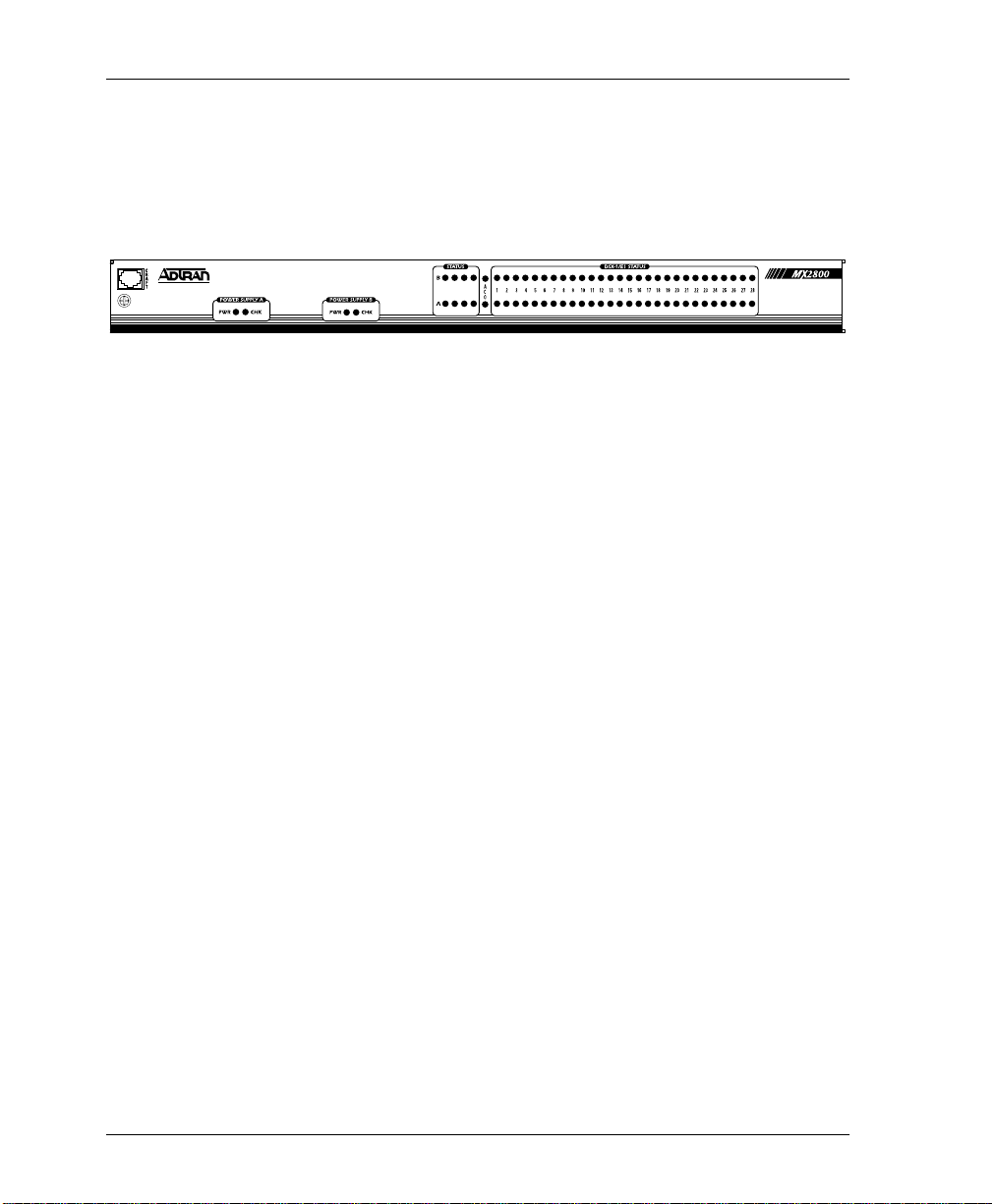
FRONT PANEL
The MX2800 STS-1 faceplate is shown below in Figure 2-4.
Descriptions of each part of the front panel follow.
Craft Port
CRAFT
The
VT-100 EIA-232 compatible interface using the supplied 8-pin
modular to DB-9 female connector and the 8-pin to 8-pin modular
cable.
Establishing Terminal Connection
port, an 8-pin modular jack, provides connection to a
A
N
A
P
C
E
L
R
T
T
M
F
Figure 2-4. MX2800 STS-1 Front Panel
To connect the MX2800 STS-1 to a VT-100 terminal, follow the
steps below:
1. Configure the VT-100 terminal for 9600, 19200, 38400, or
57600 baud, 8-bit characters, no parity, and one stop bit (xxxx,
8N1).
2. Using the terminal interface cable adapter provided by
ADTRAN, connect the DTE port of a terminal to the 8-pin
modular jack labeled
CRAFT
on the MX2800 STS-1 front
panel.
3. Initiali ze the termina l session.
Enter
4. Press
5. Enter the password. The factory default password is
lower-case). The
repeatedly until the password prompt appears.
adtran
AIN
M
ENU
M
appears (see Figure 2-5 on page
(all
2-11).
2-10 MX2800 User Manual 61200659L1-1
Page 41

Chapter 2. Installation and Operation
6. Make selections by entering the number corresponding to the
chosen parameter. Press
previous screen. End a terminal session by selecting
AIN
from the
M
ENU
M
ESC
on the keyboard to return to the
or by pressing
Figure 2-5. Terminal Main Menu
Ctrl-C
at any time.
OGOUT
L
The letter displayed in the upper left-hand co rner of the te rminal menu
indicates which controller card is active (A or B).
Navigating Within the Menus
Navigate within the MX2800 STS-1 terminal menus using the
following procedures:
If you want to... Press...
select an item the number corresponding to your choice,
and then press the
scroll left and right
within the same
screen
return to the previous
menu
61200659L1-1 MX2800 User Manual 2-11
the left and right arrow keys. Additional
screens are available when < or > is displayed in the top portion of the menu
ESC
the
key
Enter
key
Page 42

Chapter 2. Installation and Operation
If you want to... Press...
M
AIN
Ctrl-C
Ctrl-R
ENU
M
consists of the following sections:
end the terminal
session
refresh the display
The MX2800 STS-1
Status
Provides information on the current state of the STS-1, power
supplies, system, and VT/Port line s. For mor e det ailed info rmation ,
see Chapter 4, Status.
Statistics
Provides detailed statistical information (both current and
historical) for the STS-1, VT, and Port lines. For more detailed
information, see Chapter 5, Statistics.
Configuration
Sets STS-1 network , VT/Por t, and syst em manage ment pa rame ters.
For more detailed information, see Chapter 3, Configuration.
Diagnostics
Performs loopback tests over the STS-1, VT/Port lines. For more
detailed information, see Chapter 6, Diagnostics.
Logout
OGOUT
L
The
selection ends the terminal session and logs out of the
system. Password entry is requi red before a new session can begin.
The unit will also logout of a terminal session automatically if the
session remains inactive for a certain period of time. For more
information, see Terminal Timeout on page 3-35.
ACO Buttons
ACO
The
audible alarm. The buttons are recessed, so you must use a pen or
other pointed instrumen t to press them. Once you have used an
2-12 MX2800 User Manual 61200659L1-1
(alarm cut off) buttons allow you to turn off an active
ACO
Page 43

button to deactivate an alarm, it re mains disable d until the co ndition
has cleared.
Alarms can also be turned off remotely by using a selection found
S
in the
for more information.
LED Descriptions
The MX2800 STS-1 has LED status indicators for the power
supplies, the STS-1 state, the controller cards, and the individual
T1s/E1s. These LEDs are identified in the following subsections.
Power Supply A/B
PWR
The
power. The
is providing low power and needs to be checked.
Status LEDs
Chapter 2. Installation and Operation
TATUS
menu. See Acknowledge Alarms (ACO) on page 4-12
LED is active when the unit is on and receiving full
CHK
LED is active when the power suppl y i s fa il ing or
TATUS
S
The
provided are
LEDs apply to the two controller cards. The LEDs
ACT
(active),
NET, ALM
(alarm), and
PRF
(performance). Different conditions are indicated by the state of the
LED (it rema ins solid, blinks, or alternates colors). The conditio n
descriptions vary depending on whether the LED represents the
active controller card or the controller card on standby. LED
definitions are for the active cards are provided in Table 2-2 on
page 2-14. LED definitions for T1/E1 cards are provided in Table
2-3 on page 2-15.
61200659L1-1 MX2800 User Manual 2-13
Page 44

Chapter 2. Installation and Operation
LED State Card Condition
green solid Normal (All OK)
green/amber alternating Normal + Console Open
red solid Self Test Failed
ACT
amber solid Software Update in Progress
red/amber alternating Self Test Failed + Console
red blinking Card Failure
green solid Normal (All OK)
red blinking LOS
red solid LOFM. AIS-P, AIS-L, RFI-L,
NET
amber solid In Test (Local)
amber blinking In Test (Remote)
Table 2-2. LED Conditions for Active Cards
Open
RFI-P, LOP, SLM, UEQ
red/amber alternating In Test + Alarms
green solid Normal (No Alarm)
red blinking Critical Alarm
red solid Non-Critical Alarm
ALM
amber blinking Critical Alarm Suppressed
ACO
(
button was pushed)
amber solid Non-Critical Alarm Sup-
pressed (
ACO
button was
pushed)
green solid Normal (All OK)
red flash (once per event) Single/Burst CV
PRF
red blinking Continuous Code Violations
red solid XCV Threshold Exceeded
2-14 MX2800 User Manual 61200659L1-1
Page 45

Chapter 2. Installation and Operation
Table 2-3. LED Conditions for Standby Cards
LED State Card Condition
green blinking Normal (All OK)
T1/E1 Status LEDs
ACT
NET
ALM
PRF
amber solid Software Update in Progress
red blinking Self Test Failed
off Normal (All OK)
red blinking STS-1 Failure
off Normal (No Alarm)
off Normal (All OK)
These LEDs apply to each ind ividual T1 or E1. Dif ferent con ditions
are indicated by the state of the LED (its color and whether it
flashes, alternates color, or remains solid). The condition
descriptions vary depending on whether the LEDs represent T1s or
E1s of the active controller card or the controller card on standby.
Table 2-4 on page 2-16 provides LED definitions for the active a nd
standby cards.
61200659L1-1 MX2800 User Manual 2-15
Page 46

Chapter 2. Installation and Operation
Table 2-4. T1/E1 LED Conditions
LED State T1/E1 Condition
green solid Normal (All OK)
off Disabled
red blinking LOS
Active
Card
Standby
Card
red flash (once per
Single/Burst CV
event)
red/green alternating XCV Threshold Exceeded
amber solid In Test (Local)
amber blinking In Test (Remote)
red/amber alternating In Test + Alarm
off Normal (All OK) or
N/A (in the c ase o f E1 co nfiguration)
red blinking T1/E1 Failure
2-16 MX2800 User Manual 61200659L1-1
Page 47
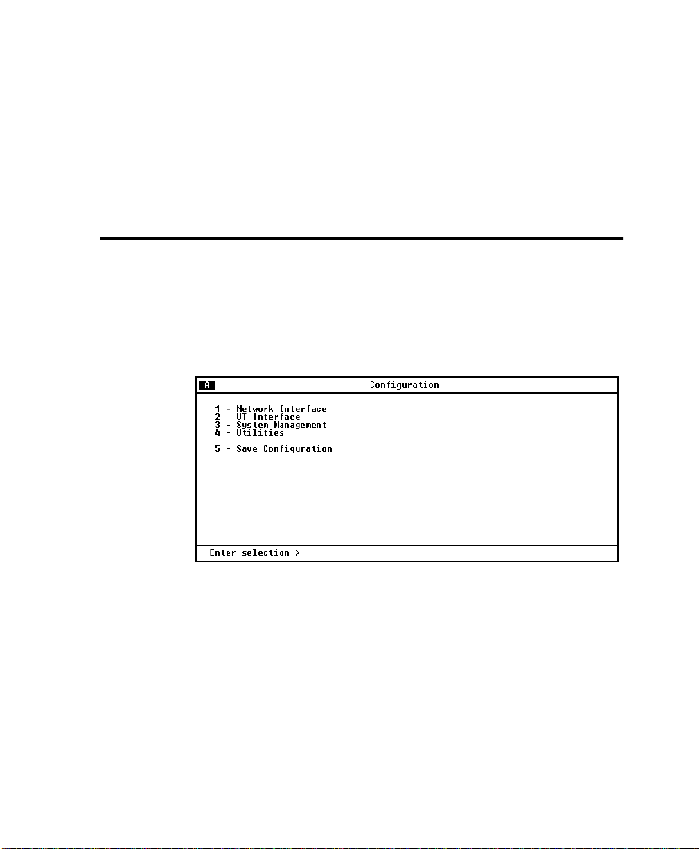
Chapter 3
Configuration
To configure the MX2800 STS-1, use a 10BaseT ethernet
connection, a SLIP/PPP modem port, or a VT-100 termi nal . Figu re
ONFIGURATION
3-1 shows the
shows the menu tree.
C
menu and Figure 3-2 on page 3-2
Figure 3-1. Configuration Menu
Detailed descriptions of the menu options shown in Figure 3-1 are
given in the following sections.
61200659L1-1 MX2800 STS-1 User Manual 3-1
Page 48

Chapter 3. Configuration
Line Length
STS-1 Configuration Timing
XCV Threshold
Network Interface VT Mode Active Controller
Protecti on Configuration Network Protection
Max Switch Threshold
Miscellaneous Loopback Timeout Min Switching Period
External Clock Configuration PRI Ext. Clock
VT/Port Mapping> First
T1 State Last
VT Interface #1-28 T1 Coding State
T1 Remote Loopbacks Line Coding
T1 Circuit Protection T1 Line Length
Hairpin Loopback Circuit Protection
Line ID Loopback Detection
VT Interface Set Multiple Apply State
Set Cross-Connect Mapping Apply Line Length
Restore VT Mapping Defaults Apply Circuit Prot ection
Protection Threshold Apply Loopback Protection
XCV Threshold Local IP Address Apply All
Gateway IP Address
Subnet Mask
Management Port Trap IP Address
Dial-up Options Trap Generation
MGMT Options TL1 Setup Read Community Name
System SNMP MGMT Options Write Community Name
Management Trap Community Name
Password
Terminal Timeout Alarm Relay Configuration
System Security IP Security Equipment Identification
Date & Time IP Hosts Syslog Setup
Miscellaneous Save on Logout
Craft baud rate
Load Default Settings Update via XMODEM
Utilities Update FLASH Software Update via TFTP Server Server ID
Config Transfer Server Filename
Load and Use
System Reset Immediate Save Config Remotely
Save Configuration Scheduled Reset Time
Figure 3-2. Configuration Menu Tree
3-2 MX2800 STS-1 User Manual 61200659L1-1
Page 49

NETWORK INTERFACE
ETWORK INTERFACE
N
Select
parameters (see Figure 3-3). Configure the MX2800 STS-1
network settings to match the STS-1 signal received from the
service provider.
Chapter 3. Configuration
to access the network configuration
Figure 3-3. Network Configuration Menu
STS-1 Configuration
Use the
STS-1 C
configure the STS-1 network settings to match your application.
Line Length
Set the line length to reflect the physical length of the STS-1
network line. Set to
225-450 feet; set to
Timing
Selects the source of timing used to derive the transmit signal. The
MX2800 STS-1 has three modes of timing operation:
UN
R
, and
E
clocking from the STS-1 receive signal. Loss of the STS-1 receive
61200659L1-1 MX2800 STS-1 User Manual 3-3
ONFIGURATION
XTERNAL
selections described below to
ONG
L
if the cabling distance is between
HORT
S
if the distance is less than 225 feet.
OOP
L
.
timing configures the unit to recover
L
OOP
REE
F
,
-
Page 50

Chapter 3. Configuration
signal or reception of AIS will cause the unit to enter hold-over
mode. The STS-1 receive signal must be valid for at least 10
seconds for the un it to exit hold-o ver mode and resto re loo p timin g.
REE-RUN
When the unit is configured for
F
timing mode, timing is
derived from a +/-20 ppm internal reference providing a SONET
Minimum Clock (SMC).
XTERNAL
Setting the unit to
E
timing mode configures the unit to
derive clocking fr om on e of t he two exter nal s ources se lect ed in the
PRI EXT. C
LOCK
SEC EXT. C
and
LOCK
options. These two entries
select which of the 28 active T1/E1 ports will be used as the
external clock source. The external clock source may be disabled (if
only one source exists, or no external clock sources are desired). A
valid clock source is one on which neither LOS or AIS conditions
exist. The selected T1/E1 may be a data carrying tributary. When
both sources are configured, failure of one source will cause the
unit to switch to the other source (if it is a valid source). Failure of
both sources will cause the unit to enter hold-over mode. At least
one external clock source must be valid for at least 10 seconds for
the unit to exit hold-over mode and restore external clock timing.
Switching between
RI
P
mary and
EC
S
ondary external clock sou rces
is non-reverting.
XCV Threshold
The
XCV T
HRESHOLD
(excessive code violations threshold) sets a
limit on code violations accepted by the unit before it switches
ISABLED
controller cards. If set t o
D
, code violations will not cause
the unit to switch controller cards. Th e threshold limits are
described in the following chart:
3-4 MX2800 STS-1 User Manual 61200659L1-1
Page 51

VT Mode
Chapter 3. Configuration
Setting The unit switches controller cards if...
more than one out of every 1,000 bits received on the
-3
1E
1E
1E
1E
STS-1 contains a code violation.
more than one out of every 10,000 bits received on
-4
the STS-1 contains a code violation.
more than one out of every 100,000 bits received on
-5
the STS-1 contains a code violation.
more than one out of every 1,000,000 bits received on
-6
the STS-1 contains a code violation.
The STS-1 can frame the 7 VT groups as either VT1.5 or VT2.
When set for VT1.5 (T1), all VT groups are set for VT1.5[TU=11]
at 1.728 Mbps and the ports are set for T1 at 1.544 Mbps. When set
for VT2 (E1), all the VT groups are set for VT2[TU-12] at
2.304 Mbps and the ports are set for E1 at 2.048 Mbps. When set
for VT2, the last 7 VTs, VT 22-28, become unavailable. All E1
ports are available for mapping.
Protection Configuration
The MX2800 STS-1 houses two controller cards for 1:1 protection
against hardware failure. The two cards can also provide network
protection, supporting two STS-1 circuits simultaneously. The
selections in this menu al low you to cust omize the unit’s protection
setup.
Active Controller
This field displays A or B, indicating the active controller card. This
setting can be used to force the controller cards to switch. For
example, if controller card
over occurs immediately.
61200659L1-1 MX2800 STS-1 User Manual 3-5
A
is active and you select B, a switch-
Page 52
Chapter 3. Configuration
Network Protection
Enable or disable the unit’s ability to automatically route
information to the backup STS-1 in the event of a primary STS-1
failure. With
is automatically routed to the backup STS-1 in the event that the
primary STS-1 fails. When
ISABLED
D
failures of the circuitry on the active controller.
When choosing a setting for
cabling and network provi sioning issues to conside r. For configuration
examples of the different modes of protection, refer to
Chapter 7, Circuit and Network Redundancy.
Max. Switch Threshold
The value entered in this field determin es the number of times per
hour the unit is allowed to switch between controller cards. If the
cards switch more than the
hour, t he unit issue s a tra p and st ops sw itchi ng card s for t he next 24
hours. The default setting is
ETWORK PROTECTION
N
ETWORK PROTECTION
N
set to
NABLED
E
, all information
is set to
, the stand-by controller will be used to protect against
ETWORK PROTECTION
N
WITCH THRESHOLD
MAX S
3
times an hour.
, there are many
within one
Min. Switching Period
After the unit switches controller cards, the number of seconds
entered in this field must pass before another card switch will be
allowed. The default setting is
10
seconds.
Miscellaneous
Loopback Timeout
ISABLED
. or
1
D
HR
.
Sets the loopback timeout to
MIN
15
3-6 MX2800 STS-1 User Manual 61200659L1-1
., 30
MIN
., 45
MIN
MIN
1
,
., 5
MIN
., 10
MIN
.
,
Page 53

External Clock Configuration
PRI Ext. Clock and SEC Ext. Clock - When timing is set to
external, these entr ies al low selec tion of the primar y and seconda ry
clock source. Any one of the 28 ports, so long as it is active, can be
used. If the selected port does go into AIS or LOS, the selected
clock becomes invalid.
VT INTERFACE
NTERFACE
VT I
The
you to activate/deactivate individual T1s and E1s and to set their
line coding, length, loopback detection, circuit protection, and line
ID string. The T1/E1 code violation threshold is also configured
through this menu. Configuration selections are described in the
sections following Figure 3-4 on page 3-7.
A VT group can be divided into ei ther three E1s or four T1s . Therefore,
when dealing with an E1 configuration, some of the fields in the
I
NTERFACE
menus do not apply (and therefore display
Chapter 3. Configuration
menu (shown in Figure 3-4 on page 3-7) allows
VT
).
N/A
Figure 3-4. VT Interface Menu
61200659L1-1 MX2800 STS-1 User Manual 3-7
Page 54

Chapter 3. Configuration
VT Interface #1-28
The VT Interface menu allows the user to map a Port (T1/E1) to a
VT, activate/deactivate the T1 and E1 mapped to the VT, and to set
the line coding, length, loopback detection, circuit protection, line
ID string, and disable/enable the hairpin loopback. Configuration
selectio ns are descri bed in the section following Figur e 3-5.
Figure 3-5. Configure VT Interface #1 Menu
VT/Port Mapping
Map a T1/E1 port to a VT. Any available port (1-28) can be
mapped to a VT. An error will be returned if the port is already
NEQUIPPED
mapped to another VT. Selecting
U
will free th e port
from mapping and disable the VT.
T1 State
T1 Coding
Set unused T1 lines to
ISABLED
D
. Set used T1 lines to
NABLED
E
.
Set the line code for each individual T1 interface to match the
connected device. The choices available for T1 are
3-8 MX2800 STS-1 User Manual 61200659L1-1
AMI
and
B8ZS
.
Page 55

T1 Line Length
Set the line length for each T1 interface according to the distance
from the MX2800 STS-1 to your DTE device. Set to
attached DTE device only supports DS1 levels.
T1 Remote Loopback
Allows a selected T1 to re spond to CSU or NIU loopbacks arriving
from the STS-1 side.
T1 Circuit Protection
T1 Circuit Protection determines which circuit will be allowed to
initiate a pr otection switch if a failure in the circuitry for that
channel is detected. If a T1 is set to
circuitry of that one channel will not cause a protection switch. If
set to
protection switch to occur (depending on the
HRESHOLD
T
Hairpin Loopback
NABLED
E
Chapter 3. Configuration
ISABLED
D
, then the failure of the
, then the failure of a channel could cause a
ROTECTION
P
setting).
-7.5 DB
if the
Hairpin back the VT to the STS-1 sign al for dr opping farther down
the SONET ring.
Line ID
Enter user-configur able text strings to name the indiv idual T1 li nes.
This field will accept up to 18 alpha-numeric characters, including
spaces and special characters (such as an underbar).
Set Multiple
ULTIPLE
SET M
disable a contiguous group or all of the VTs at one time. It may also
be used to make multiple changes to the line coding, length, circuit
protection or loopba ck dete ction of a contiguo us group or all VTs at
one time.
61200659L1-1 MX2800 STS-1 User Manual 3-9
(see Figure 3-6 on page 3-10) can be used to enable/
Page 56

Chapter 3. Configuration
To make changes to all VTs, set
the necessary changes and select
IRST
F
PPLY ALL
A
to 1 and
AST
L
to 28. Make
(or select the
A
PPLY
option that corresponds to the change made) before leaving the
IRST
menu. T o make cha nges to some of the VTs, set the
F
fields to correspond to the lines you want to change. Select
LL
A
(or select th e
PPLY
A
option that corresponds to the change
and
A
AST
L
PPLY
made). You can now either leave the menu or continue t o enter new
F
IRST
and
AST
L
numbers for other lines. Remember to apply the
settings following each change.
Figure 3-6. Set Multiple Menu
Set Cross-Connect Mapping
Any VT can be cross-connect mapped to any available T1/E1 port.
NEQUIPPED
Selecting
default mapping for VTs 1-28 is 1-to-1.
3-10 MX2800 STS-1 User Manual 61200659L1-1
U
will free the port and disable the VT. The
Page 57

Figure 3-7. Set Cross-Connect Mapping Menu
Restore Defaults
Restores VT mapping to 1-to-1 mapping.
Restore VT Mapping Defaults
Chapter 3. Configuration
Select
ESTORE
R
APPING DEFAULTS
VT M
from the
VT I
NTERFACE
configuration menu. The following message will display on the
screen:
Select
!WARNING! R
ONFIRM
C
to continue or press
ESTORING DEFAULTS WILL DISRUPT TRAFFIC
Esc
to abort.
.
Protection Threshold (1-28)
ROTECTION THRESHOLD
P
The
NABLED
E
lines must fail befor e a card switch o ccurs. If you want the
failure of a single protected (enabled) line to cause a card switch,
ROTECTION THRESHOLD
set the
61200659L1-1 MX2800 STS-1 User Manual 3-11
P
setting determines how many of the
to 1. Choices include 1 through 28.
Page 58

Chapter 3. Configuration
XCV Threshold
Set a limit on code violations (CVs) accepted by the unit over an
individual T1/E1 line be fore it swi tches cont roller c ards (see Figure
3-8). If set to
switch controller cards. The threshold limits are described in the
following chart:
Setting The unit switches controller cards if...
1E
1E
1E
1E
ISABLED
D
more than one out of every 1,000 bits received on a
-3
, code violations will not cause the unit to
T1/E1 line contains a code violation
more than one out of every 10,000 bits received on a
-4
T1/E1 line contains a code violation.
more than one out of every 100,000 bits received on a
-5
T1/E1 line contains a code violation.
more than one out of every 1,000,000 bits received on
-6
a T1/E1 line contains a code violation.
Figure 3-8. XCV Threshold Menu
3-12 MX2800 STS-1 User Manual 61200659L1-1
Page 59
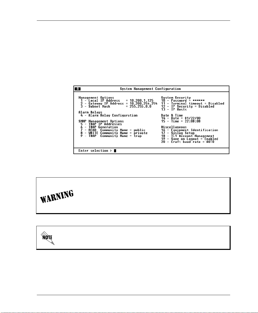
SYSTEM MANAGEMENT
Configure the MX2800 STS-1 for management through SNMP,
Telnet, or a VT-100 interface (see Figure 3-9). Embedded SNMP
and Telnet are available via a SLIP/PPP modem port or 10BaseT
ethernet interface. This menu also includes options used to
customize your unit’s alarm and trap generation, security setup , and
equipment identification.
Figure 3-9. System Management Configuration Menu
Chapter 3. Configuration
Configuration changes to
A
DDRESS
M
ODEM BAUD RATE
,
S
UBNET MASK
, and
L
IP A
OCAL
,
M
ANAGEMENT PORT
IP H
will not be implement ed unle ss
OSTS
DDRESS
,
G
ATEWAY
,
M
ODEM MODE
IP
,
all Telnet session s are closed. Chan ges made while Telnet s essions
are active will invoke a warning message on the console.
If the unit is not equipped with an internal modem, the
option and
P
ORT
61200659L1-1 MX2800 STS-1 User Manual 3-13
D
IALUP OPTIONS
will not be available.
M
ANAGEMENT
Page 60

Chapter 3. Configuration
Management Options
Local IP Address
Enter the MX2800 STS-1 IP address. This IP addre ss appli es to the
LAN or modem port (when configured for PPP or SLIP). This
address is available from your network administrator.
Gateway IP Address
Enter the gateway IP addre ss of the MX2800 STS- 1. This address i s
necessary only if the MX2800 STS-1 and the network manager are
connected through a ga te way node. If an IP packet is t o be se nt to a
different network, the unit sends it to the gateway.
Subnet Mask
Enter the subnet mask of the MX2800 STS-1. This address is
available from your network administrator.
Management Port
Assign the management port as either LAN or Modem. The Modem
setting applies only to units equipped with an internal modem.
Dialup Options
Configure the dialu p capab ilit ies o f the MX2800 STS-1 (see Figu re
3-10 on page 3-15). These options apply only to units equipped
with an inter nal modem.
3-14 MX2800 STS-1 User Manual 61200659L1-1
Page 61

Chapter 3. Configuration
Figure 3-10. Dialup Options Menu
Primary and Secondary Phone Numbers
When the MX2800 STS-1 dials out to send a trap, it first dials the
RIMARY PHONE NUMBER
P
ECONDARY PHONE NUMBER
S
. If the call is unsuccessful, it tries the
. Attempts between the tw o numbers
continue until a call is established and the trap is reported (or until
each number’s maximum for redial attempts is reached; see
Maximum Redial Attempts below).
Initializing String
The AT command entered in this field is used to initialize the
modem. Normally, this field should be left at the default setting
(ATZ).
Dial String
The AT command entered in this field causes the modem to dial
out. Normally, this field should be left at the default setting
(ATDT).
Maximum Redial Attempts
The MX2800 STS-1 attempts to es tablish a c all the number of times
entered in this field. If a successful call is not established after the
final attempt, the MX2800 STS-1 discards the trap messages.
61200659L1-1 MX2800 STS-1 User Manual 3-15
Page 62

Chapter 3. Configuration
Idle Timeout
After establishing a call and sending trap messages, the MX2800
STS-1 remains online for the amount of seconds entered in this
field. If the field is set to 0, the unit hangs up as soon as the trap is
sent.
Connection Timeout
The MX2800 STS-1 waits for a connection the amount of seconds
entered in this field. Timing begins as soon as the dial command is
issued. This field must be set for greater than 20 seconds.
Pause Between Calls
The MX2800 STS-1 waits between redial attempts the number of
seconds entered in this field.
Dialout On Trap
Enable or disable the MX2800 STS-1’s ability to dial out to report
traps.
M
configured for
VT-100
reports error conditions
ODEM MODE
in plain ASCII with the following information:
• The Unit ID value programmed in the
portion of the
Management on page 3-13)
• A trap code indicating the error condition
• A text description of the fault
• The date and time when the error was logged
ODEM MODE
M
When
YSTEM MANAGEMENT
S
is configured for
QUIPMENT IDENTIFICATION
E
screen (see System
PPP
or
SLIP
, the MX2800
STS-1 logs into the PPP/SLIP host and reports the error conditions
to the hosts designated under
T
RAP
IP A
DDRESSES
(see Trap IP
Addresses on page 3-25).
Answer on Ring
Enable or disable the MX2800 STS-1’s ability to accept incoming
calls. If enabled, incoming calls are automatically answered by the
MX2800 STS-1, allowing you to remotely perform management
functions.
3-16 MX2800 STS-1 User Manual 61200659L1-1
Page 63

Chapter 3. Configuration
Modem Mode
Select the
SLIP
or
). The
Modem
Modem
port function for your application (
port, located on the rear panel of the
VT-100, PPP
MX2800 STS-1, provides a telephone line (POTS) for connection
to the internal V.34 modem. This setting applies only if the
ANAGEMENT PORT
M
ODEM
M
.
(see Management Port on page 3-14) is set to
Modem Baud Rate
Set the maximum operating speed of the Modem port (1200, 2400,
4800, 9600, 19200, and 38400 bps).
Hangup
Selecting this option forces the MX2800 STS-1 to end an
established call.
Last Modem Response
This status field displays the last modem response to the MX2800
STS-1. Possible responses include
NOD
IALTONE
, and
NO C
ARRIER
.
OK, C
ONNECT
USY
,
RROR
E
,
B
,
,
61200659L1-1 MX2800 STS-1 User Manual 3-17
Page 64

Chapter 3. Configuration
Alarm Relays
Alarm Relay Configuration
Enables audible a nd visibl e alarms for spec ific er ror condi tions ( see
Figure 3-11). The following charts describe the alarm conditions
found in each menu. Conditions marked in the charts with an
asterisk (*) sound the critical alarm when enabled. All other
conditions sound the non-critical alarm.
Figure 3-11. Alarm Relay Configuration Menu
3-18 MX2800 STS-1 User Manual 61200659L1-1
Page 65

STS-1 Alarms
Alarm Description
LOS (Loss of Signal)
The unit has lost the network receive signal.
LOF (Loss of Framing)
The unit detects a framing loss from the
network.
LOP (Loss of Pointer)
The unit is unable to detect a valid pointer in the
receive signal.
LOMF (Loss of Multiframe)
The unit detects loss of H4 multiframe from the
network.
AIS-L (Line Alarm Indication Signal)
The unit is receiving a line alarm indication
signal. The Section Terminating Equipment
generates AIS-L after detecting LOS or LOF.
AIS-P (Path Alarm Indication Signal)
The unit is receiving a path alarm indication
signal. AIS-P is defined as all ones in bytes H1,
H2, and H3 as well as all ones in the entire STS
synchronous payload envelope.
Chapter 3. Configuration
RFI-L (Line Remote Failure Indication)
The unit is receiving a line remote failure
indication. RFI-L is declared when the incoming
line remote defect indication (RDI-L, “110”
pattern in bits 6, 7, and 8 of the K2 line overhead
byte) lasts for 2.5 +/- 0.5 seconds.
RFI-P (Path Remote Failure Indication)
The unit is receiving a path remote failure
indication. RFI-P is declared when the incoming
path remote defect indication (RDI-P, “1” in bit 5
of the G1 path overhead byte for contiguous
frames) lasts for 2.5 +/- 0.5 seconds.
61200659L1-1 MX2800 STS-1 User Manual 3-19
Page 66

Chapter 3. Configuration
Alarm Description
SLM-P (Path Signal Level Mismatch)
A received signal label is mismatched if it does
not equal the locally provisioned value or the
value “equipped non-specific”.
UEQ-P (Path Unequipped)
The path is unequipped if it is not provisioned.
Byte C2 of the STS path overhead is set to zero.
XCV (Excessive Code Violati ons )
The controller is receiving excessive code
violations exceeding the threshold set by the
user (see
XCV Threshold
on page 3-12).
TLOS (Transmit Loss of Signal)
The transmitter has failed.
JTRACE (STS Receive Path Trace)
Received in the J1 path overhead byte. This
byte is used to repetitively transmit a 64 byte
(last two bytes are a fixed CR/LF) string so the
receiving terminal in a path can verify its
continued connection to the intended
transmitter.
3-20 MX2800 STS-1 User Manual 61200659L1-1
Page 67

Chapter 3. Configuration
VT/Port Alarms
Alarm Description
LOS (T1/E1 Loss of Signal)
The unit has lost the receive signal on a T1/E1.
CAIS (Carrier Side AIS)
The T1 is receiving all ones from the STS side
of the network.
LAIS (Loop Side AIS)
The T1 is receiving all ones from the DSX-1
interface.
XCV (T1/E1 Excessive Code Violations)
The controller card is receiving excessive code
violations, exceeding the threshold set by the
user (see
XCV Threshold
on page 3-12).
VT-LOP (VT Path Loss of Poin ter)
A VT LOP defect is declared when either a valid
pointer is not detected in eight consecutive VT
superframes, or when eight consecutive VT
superframes are detected with the NDF set to
“1001” without a valid concatenation indicator. A
VT LOP failure is declared when the VT LOP
defect persists for 2.5 +/- 0.5 seconds.
VT-AIS (VT Path Alarm Indication Signal)
The unit is receiving a VT path alarm indication
signal. VT-Path AIS is specified as all ones in
bytes V1, V2, V3, and V4, as well as all ones in
the entire VT synchronous payload envelope. A
VT-Path AIS failure is declared when the
VT-Path AIS defect persists for 2.5 +/- 0.5
seconds.
61200659L1-1 MX2800 STS-1 User Manual 3-21
Page 68

Chapter 3. Configuration
Alarm Description
VT-RFI (VT Path Remote Failure Indication)
The unit is receiving a VT path remote failure
indication. VT-RFI is declared when the
incoming VT path remote defect indication (VTRDI, “1” in bit 4 of the VT-Path Overhead byte
(V5) in five contiguous frames) lasts for
2.5 +/- 0.5 seconds.
VT-SLM (VT Path Signal Label Mismatch)
A received signal label is mismatched if it does
not equal the locally provisioned value or the
value “equipped non-specific”.
VT-UEQ (VT Path Unequipped)
The VT path is not provisioned. Byte V5 of the
STS path overhead is set to zero.
3-22 MX2800 STS-1 User Manual 61200659L1-1
Page 69

Chapter 3. Configuration
System Alarms
Alarm Description
Protection Switching
Card Failure A controller card has failed. This is a critical
alarm only when the back-up card is not
installed or is not working properly.
Protection
Switch
Communication
Fail
All data has been routed from the primary card
to the stand-by card.
Communication between controller cards A and
B has failed.
System Timing
Clock Status When enabled, an abnormal clock status
condition will cause the CRITICAL relay to be
thrown.The alarm will remain active until the
condition clears or the alarm is acknowledged
by the user.
Clock Source
Change
When enabled, a change in the clock source will
cause the NON-CRITICAL relay to be thrown.
The alarm will remain active until the condition
clears or the alarm is acknowledged by the user.
PRI EXT Clock
Status
When enabled, a fault condition (LOS/AIS or
FAIL) on the PRImary or SEConday external
clock will cause the NON-CRITICAL relay to be
thrown. The alarm will remain active until the
condition clears or the alarm is acknowledged
by the user.
SEC EXT Clock
Status
When enabled, a fault condition (LOS/AIS or
FAIL) on the PRImary or SEConday external
clock will cause the NON-CRITICAL relay to be
thrown. The alarm will remain active until the
condition clears or the alarm is acknowledged
by the user.
61200659L1-1 MX2800 STS-1 User Manual 3-23
Page 70

Chapter 3. Configuration
Alarm Description
Activity Loss
Status
When enabled, the CRITICAL relay will be
thrown if the Activity Loss Status indicates the
failure of an internal clock. The alarm will rema in
active until the condition clears or the alarm is
acknowledged by the user.
Power Supply Alarms
Alarm Description
Malfunction Power supply card is no longer working. The
unit has switched to the backup power supply or
battery backup.
Power Low Power supply’s output level is abnormally low.
Power Fail Power supply card’s input power is lost.
Bat. Backup
Active
Battery charger has lost its AC source and is
now running off the battery backup.
Battery Low B attery backup has reached a critical energy
point at which it may be unable to supply the unit
with sufficient power to maintain operation.
Temperature
High
Power supply card temperature is above
normal.
Temperature
Critical
3-24 MX2800 STS-1 User Manual 61200659L1-1
Power supply card temperature is so high that it
may suffer damage.
Page 71
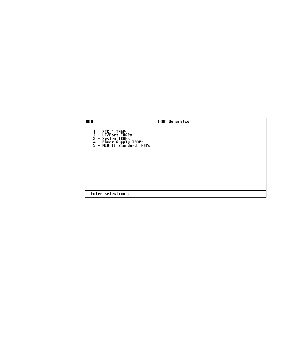
SNMP Management Options
Trap IP Addresses
Enter up to five IP addresses of SNMP managers to which the
MX2800 STS-1 sends traps.
Trap Generation
Use this menu (see Figure 3-12) to designate whi ch error condit ions
will cause the unit to send trap messages.
Chapter 3. Configuration
Figure 3-12. Trap Generation Menu
61200659L1-1 MX2800 STS-1 User Manual 3-25
Page 72

Chapter 3. Configuration
STS-1 Active Alarm Traps
Trap If enabled, the unit issues a trap when...
LOS (Loss of Signal)
The controller card has lost the network receive
signal.
LOF (Loss of Framing)
The controller card detects a loss of framing
from the network.
LOMF (Loss of Multiframe)
The controller card detects loss of H4
multiframe from the network.
AIS-L (Line Alarm Indication Signal)
The controller card is receiving a line alarm
indication signal. Line AIS defect is detected as
a "111" pattern in bits 6, 7, and 8 of the K2 byte
in five consecutive frames.
AIS-P (Path Alarm Indication Signal)
The controller card is receiving a path alarm
indication signal. AIS-P is defined as all ones in
bytes H1, H2, and H3 as well as all ones in the
entire STS synchronous payload envelope.
RFI-L (Line Remote Failure Indication)
The controller card is receiving a line remote
failure indication. RFI-L is declared when the
incoming line remote defect indication (RDI-L,
"110" pattern in bits 6,7, and 8 of the K2 line
overhead byte) last for 2.5 +/- 0.5 seconds.
RFI-P (Path Remote Failure Indication)
The controller card is receiving a path remote
failure indication. RFI-P is declared when the
incoming path remote defect indication (RDI-P,
"1" in bit 5 of the G1 path overhead byte for 5
contiguous frames) last for 2.5 +/- 0.5 seconds.
3-26 MX2800 STS-1 User Manual 61200659L1-1
Page 73

Chapter 3. Configuration
Trap If enabled, the unit issues a trap when...
UEQ-P (Path Unequipped)
The controller card detects that the path is
unequipped. The path is unequipped if it is not
provisioned. Byte C2 of the STS path overhead
is set to zero.
SLM-P (Path Signal Label Mismatch)
The controller card is detecting a signal label
mismatch. A received signal label is
mismatched if it does not equal the locally
provisioned value or the value "equipped nonspecific".
TX LOS (Transmit Loss of Signal)
The controller card's transmitter has failed.
XCV (Excessive Code Violations)
The controller is receiving excessive code
violations exceeding the threshold set the user
XCV Threshold
(see
on page 3-12).
In Test The STS-1 is going in test (applies to the Active
controller card only).
JTRACE ( STS receive path trace)
The controller card has detected a change in the
receive path trace message. The message is
received in the J1 path overhead byte. This byte
is used to repetitively transmit a 64 byte (last two
bytes are a fixed CR/LF) string so the receiving
terminal in a path can verify its continued
connection to the intended transmitter.
61200659L1-1 MX2800 STS-1 User Manual 3-27
Page 74

Chapter 3. Configuration
STS-1 Standby Alarm Traps
Trap If enabled, the unit issues a trap when...
LOS (Loss of Signal)
The controller card has lost the network receive
signal.
LOF (Loss of Framing)
The controller card detects a loss of framing
from the network.
LOMF (Loss of Multiframe)
The controller card detects loss of H4
multiframe from the network.
AIS-L (Line Alarm Indication Signal)
The controller card is receiving a line alarm
indication signal. Line AIS defect is detected as
a "111" pattern in bits 6, 7, and 8 of the K2 byte
in five consecutive frames.
AIS-P (Path Alarm Indication Signal)
The controller card is receiving a path alarm
indication signal. AIS-P is defined as all ones in
bytes H1, H2, and H3 as well as all ones in the
entire STS synchronous payload envelope.
3-28 MX2800 STS-1 User Manual 61200659L1-1
Page 75

Chapter 3. Configuration
Trap If enabled, the unit issues a trap when...
RFI-L (Line Remote Failure Indication)
The controller card is receiving a line remote
failure indication. RFI-L is declared when the
incoming line remote defect indication (RDI-L,
"110" pattern in bits 6,7, and 8 of the K2 line
overhead byte) last for 2.5 +/- 0.5 seconds.
RFI-P (Path Remote Failure Indication)
The controller card is receiving a path remote
failure indication. RFI-P is declared when the
incoming path remote defect indication (RDI-P,
"1" in bit 5 of the G1 path overhead byte for 5
contiguous frames) last for 2.5 +/- 0.5 seconds.
UEQ-P (Path Unequipped)
The controller card detects that the path is
unequipped. The path is unequipped if it is not
provisioned. Byte C2 of the STS path overhead
is set to zero.
SLM-P (Path Signal Label Mismatch)
The controller card is detecting a signal label
mismatch. A received signal label is
mismatched if it does not equal the locally
provisioned value or the value "equipped nonspecific".
TX LOS (Transmit Loss of Signal)
The controller card's transmitter has failed.
XCV (Excessive Code Violations)
The controller is receiving excessive code
violations exceeding the threshold set the user
XCV Threshold
(see
61200659L1-1 MX2800 STS-1 User Manual 3-29
on page 3-12).
Page 76

Chapter 3. Configuration
VT/Port Traps
Trap If enabled, the unit issues a trap when...
LOS (T1/E1 Loss of Signal)
The unit has lost the receive signal on a T1/E1.
CAIS (Carrier Side AIS)
The T1 is receiving all ones from the STS side
of the network.
LAIS (Loop Side AIS)
The T1 is receiving all ones from the DSX-1
interface.
XCV (T1/E1 Excessive Code Violations)
The controller card is receiving excessive code
violations, exceeding the threshold set by the
user (see
XCV Threshold
on page 3-12).
Failure
VT-LOP (VT Path Loss of Poin ter)
When the unit fails to find a valid VT pointer. A
VT LOP defect is declared when either a valid
pointer is not detected in eight consecutive VT
superframes, or when eight consecutive VT
superframes are detected with the NDF set to
"1001" without a valid concatenation indicator. A
VT LOP failure is declared when the VT LOP
defect persists for 2.5 +/- 0.5 seconds.
VT-AIS (VT Path Alarm Indication Signal)
The unit is receiving a VT path alarm indication
signal. VT-Path AIS is specified as all ones in
bytes V1, V2, V3, and V4, as well as all ones in
the entire VT synchronous payload envelope. A
VT-Path AIS failure is declared when the VTPath AIS defect persists for 2.5 +/- 0.5 seconds.
3-30 MX2800 STS-1 User Manual 61200659L1-1
Page 77

Chapter 3. Configuration
VT-RFI (VT Path Remote Failure Indication)
The unit is receiving a VT path remote failure
indication. VT-RFI is declared when the
incoming VT path remote defect indication (VTRDI, "1" in bit 4 of the VT-Path Overhead byte
(V5) in five contiguous frames) lasts for 2.5 +/-
0.5 seconds.
VT-SLM (VT Path Signal Label Mismatch)
The controller card is detecting a signal label
mismatch in the VT path. A received signal label
is mismatched if it does not equal the locally
provisioned value or the value "equipped nonspecific".
VT-UEQ (VT Path Unequipped)
The controller card detects that the VT path is
unequipped. The VT path is not provisioned.
Byte V5 of the STS path overhead is set to zero.
System Traps
Trap If enabled, the unit issues a trap when...
Protection Switching
Protection Switch all data has been routed from the primary card
to the stand-by card.
Card Removed a controller card has been removed.
Card Failure a controller card has failed. This is a critical
alarm only when the back-up card is not
installed or is not working properly.
Communication
Fail
Max Switches the
61200659L1-1 MX2800 STS-1 User Manual 3-31
communication between controller cards A
and B has failed.
AX SWITCH THRESHOLD
M
Max. Switch Threshold
is reached (see
on page 3-6).
Page 78

Chapter 3. Configuration
Trap If enabled, the unit issues a trap when...
System Timing
Clock Status there is a change in clock status. The clock
status can be any of the following values:
ORMAL
N
– clock synchronization is
operating normally.
ECOVERING
R
– clock synchronization is in
the process of recovering from a fault.
OSS OF SOURCE
L
– the reference clock
source has become invalid
UT OF RANGE
O
– the clock synchronizatio n
circuit is unable to track the reference
source.
UT OF LOCK
O
– the clock synchronization
circuit is unable to lock to the reference
source.
Clock Source
Change
PRI EXT Clock
Status
there is a Clock Source Change event
indicating that the unit has switched clock
sources. The values for the clock source
change alarm are:
Loop
PRI Ext
SEC Ext
Free-run
Holdover
a failure condition is encountered on either the
PRImary or SECondary clock sources (if
configured). The possible values for this alarm
are:
ISABLED
D
ORMAL
N
VAILABLE
A
LOS/AIS
AIL
F
NAVAILABLE
U
3-32 MX2800 STS-1 User Manual 61200659L1-1
Page 79

Chapter 3. Configuration
Trap If enabled, the unit issues a trap when...
SEC EXT Clock
Status
Activity Loss
Status
a failure condition is encountered on either the
PRImary or SECondary clock sources (if
configured). The possible values for this alarm
are:
ISABLED
D
ORMAL
N
VAILABLE
A
LOS/AIS
AIL
F
NAVAILABLE
U
there is a critical hardware failure in which a
clock source has become inactive. The
MX2800 STS-1 continually checks for activity
on all of its internal clock sources as part of its
status monitoring. If any clock source fails, the
corresponding clock source will be displayed
in the status menu and a TRAP/Syslog
condition will be generated. If all clocks are
operating normally, no indication is shown on
the menu. Again, this conditi on is only
encountered during a hard card failure and the
customer should contact ADTRAN technical
support if this occurs.
Power Supply Alarm Traps
Trap If enabled, the unit issues a trap when...
Card Removed the power supply card has been removed
Malfunction the power supply card is no longer working and
the unit has switched to the backup power
supply or battery backup
Card Failure the power supply card has failed
Power Low the power supply’s output level is abnormally
low
61200659L1-1 MX2800 STS-1 User Manual 3-33
Page 80

Chapter 3. Configuration
Trap If enabled, the unit issues a trap when...
Bat. Backup
Active
Battery Low the battery backup has reached a critical energy
Temperature
High
Temperature
Crit
MIB II Standard Alarm Traps
Trap If enabled, the unit issues a trap when...
Cold Start the unit is first powered up
Link Up the STS-1 is up with no alarms
Link Down the STS-1 is in alarm
Auth. Failure an attempt has been made by an unauthorized
Read Community Name
Battery charger has lost its AC source and is
now running off the battery backup
point at which it may be unable to supply the unit
with sufficient power to maintain operation
the power supply card is getting too hot
the power supply card temperature is so high
that it may suffer damage
user to access the unit
Enter the authentication strings used for SNMP management.
Match the MX2800 STS-1 to the SNMP manager for read
privileges.
Write Community Name
Enter the authentication strings used for SNMP management.
Match the MX2800 STS-1 to the SNMP manager for write
privileges.
Trap Community Name
Enter the identifi cation stri ng used for t rap management. Th is string
accompanies all traps transmitted by the MX2800 STS-1.
3-34 MX2800 STS-1 User Manual 61200659L1-1
Page 81

System Security
Password
Set the password required at logi n (up to 32 chara cters). The de fault
password is
Terminal Timeout
Set the amount of time the terminal or Telnet session remains
inactive before a utom atica lly cl osing the sessi on, requ ir ing the user
to log in again. The options include
MIN
15
IP Security
.,
60
adtran
MIN
., or
(all lower case).
DAY
1
.
ISABLED
D
Chapter 3. Configuration
MIN
1
,
.,
MIN
5
.,
IP Hosts
Date & Time
Enable or di sable the
IP S
ECURITY
option. If
NABLED
E
, the unit
accepts management commands and Telnet sessions from the IP
OSTS
addresses entered into the
IP H
fields.
Enter up to 16 IP addresse s of manag ement st ation s from whi ch the
unit should accept management commands. These addresses are
only applicable if
IP S
ECURITY
is
NABLED
E
(see previous
paragraph).
Enter date and time information. Enter the month, date, and year
separated by forward slashes (02/23/00). Enter the time in military
format separated by colons (13:15:25).
61200659L1-1 MX2800 STS-1 User Manual 3-35
Page 82

Chapter 3. Configuration
Miscellaneous
Equipment Identification
These fields allow you to store information that identifies the unit.
Unit ID
Provides a user-configurable text string for the name of the
MX2800 STS-1. This name can help you distinguish between different installations. You can enter up to 32 alpha-numeric characters in this field, incl uding spaces and specia l charact ers (such as an
underbar). This information is locally stored and displayed in the
upper right-hand corner of the MX2800 STS-1 terminal screens.
STS-1 J1 Path Trace
Tx
– 62 byte string to be transmitted in the J1 Path Trace (CR/LF
are automatically appended to the string).
Rx
– 62 byte string received in the J1 Path Trace.
Syslog Setup
Selections include
EVEL
L
, and
Transmission
NABLE
E
OST FACILITY
H
ISABLE
D
or
RANSMISSION
T
.
the transmission of log events to the external
OST
H
,
IP A
DDRESS
S
,
EVERITY
Syslog server. You must first define the host IP address.
Host IP Address
Specifies the IP address of the external server that is running the
Syslog host daemon.
Severity Level
Specifies the lowest level of severity that causes messages to be
logged to the Syslog server. The levels are listed in Table 3-1 on
page 3-37, in order of decrea sing severi ty. Any message at or above
a selected s everity level will be logged if a transmiss ion is enabled.
3-36 MX2800 STS-1 User Manual 61200659L1-1
Page 83

Chapter 3. Configuration
Table 3-1. Syslog Severity Levels
Level Description
Emergency
Alert
Critical
Error
Warning
Notice
Info
Debug
Host Facility
Specifies the faci lity desti nation of l og events. Faci lities are located
on the host and are man aged by t he Syslo g host d aemon runn ing on
either a UNIX machine or a PC. Options include
TL1 Account Management
This menu allows for TL1 account management. Before any TL1
session can be initiated, the user must be authenticated. This user
database provides access to the current list of TL1 users and their
associated passwords and privileges. This information is used
strictly for TL1 purposes.
The system is unusable
An action must be taken immediately
Shows critical conditions
Shows error conditions
Shows warning conditions
Shows normal, but significant, conditions
Shows informational messages
Shows a debug-level message
OCAL
L
0-7
.
Each row in the menu contains the associated information for a
particular user. The username must be defined before an associated
password or privilege can be assigned, and a privilege can only be
defined after a password is assigned. All passwords are hidden for
security purposes and are never shown in “clear text” form.
Usernames and password entries are automatically converted to
uppercase on entry. A user is prevented from del eting himself when
editing the database over a TL1 session.
61200659L1-1 MX2800 STS-1 User Manual 3-37
Page 84

Chapter 3. Configuration
Save on Logout
Craft baud rate
ISABLED
Currently, a user’s privilege can be one of three values:
G
UEST
, or
A
DMIN
. A
ISABLED
D
account behaves as expected, and
D
,
effectively disables all access while preserving account
UEST
information. A
autonomous messages, but no user database access. An
G
account allows alarm database access and
A
DMIN
account is a guest account with user database access.
Any time the MX2800 STS-1 conf igurati on is saved to FLASH, the
TL1 user database is saved as well. The user database is also saved
(as required) when any TL1 session is close (i.e., via a TL1
‘CANC-USER’ request).
NABLE
E
D
Possible baud rate settings for the front panel
are:
this function to save the configuration when you logout.
ISABLE
if you do not want to save the configuration.
RAFT
C
UTO
A
9600, 19200, 38400
,
, and
57600
.
port. Choices
UTILITIES
TILITIES
U
The
STS-1 system information for both controller cards (including selftest results), revert to default configuration settings, flash-load a
new version of software, transfer configuration information to and
from a TFTP server, and reset the syste m. Possible results for the
self-test are listed in the chart following Figure 3-13 on page 3-39.
3-38 MX2800 STS-1 User Manual 61200659L1-1
menu (see Figure 3-13) allows you to view MX2800
Page 85

Chapter 3. Configuration
Figure 3-13. System Utilities Menu
If the self test results are... Then...
PASS the self-test was successful and the
unit is ready to use.
BAD RAM DATA
BAD RAM ADDRESS
BAD CODE CHECKSUM
contact ADTRAN Technical
Support. See the front section of
this manual for more information.
BAD BOOT SECTOR
IOX PROGRAM FAILURE
AFE PROGRAM FAIL URE
MODEM FAILURE
ETHERNET FAILURE
STS-1 FAILURE
DSX FAILURE
AVE CONFIGURATION
CONFIGURATION
CORRUPT
S
select
the main
ONFIGURATION
C
from
menu. If
condition persists, contact ADTRAN
Technical Support.
61200659L1-1 MX2800 STS-1 User Manual 3-39
Page 86

Chapter 3. Configuration
Load Default Settings
Loading the default settings will disable all STS-1 ports.
OAD DEFAULT SETTINGS
L
Select
screen will display
traffic on all ports.
The IP Address, Default Gateway, and subnet mask will not be reset
when default settings are loaded.
Update FLASH Software
PDATE FLASH SOFTWARE
U
Select
software using either XMODEM protocol or Trivial File Transfer
Protocol (TFTP).
Update Via XMODEM
PDATE VIA
U
Select
menu; then select
TART
1-S
terminal menu program (the XMODEM utility is available under
most terminal programs). If you wish to cancel a transfer in
progress, press
from this menu, start the XMODEM transfer from your
Ctrl-X
TILITIES
PDATE
U
U
TILITIES
U
menu. The
Esc
menu to update
FLASH S
to abort.
OFTWARE
from the
!WARNING! Defaulting configuration will disrupt
ONFIRM
Select
C
to proceed or press
from the
XMODEM
TART
1-S
from the
to begin the transfer. Once you select
three times.
This function is availabl e only when updatin g the software th rough the
CRAFT
3-40 MX2800 STS-1 User Manual 61200659L1-1
port.
Page 87

Update via TFTP Server
Chapter 3. Configuration
Select
menu displays, allowing you to enter the IP address and file name
of the file you want to download to the unit. Once this information
is entered, select
Config Transfer
Select
and from a TFTP server. The
save the MX2800 STS-1 configuration as a backup file, so you can
use the same configuration with multiple MX2800 STS-1 units.
Only one configuration transfer session (upload or download) can
be active at a time.
Before using
IP address, subnet mask, and de fault gatewa y (if requir ed), and shoul d
be connected to an Ethernet network.
Saving to a TFTP Server
To save current configuration information to a TFTP server, follow
the steps listed below.
PDATE VIA
U
ONFIG TRANSFER
C
ONFIG TRANSFER
C
TFTP
TART/STOP TRANSFER
S
SERVER
from the
TILITIES
U
menu. A new
.
TILITIES
from the
U
ONFIG TRANSFER
C
menu to transfer files to
option also let s you
, the MX2800 STS-1 should have a valid
1. Set the
ERVER
S
IP A
DDRESS
field to the IP address of the
machine running the TFTP server program.
If you are using the ADTRAN TFTP server, the IP address
displays in the
ERVER
S
IP A
DDRESS
field. For other TFTP
servers, please refer to the appropriate documentation.
2. Change the TFTP Server Filename to a unique filename. This
61200659L1-1 MX2800 STS-1 User Manual 3-41
Page 88

Chapter 3. Configuration
will be the name of the configuration file saved to the remote
server.
Some TFTP servers constra in the format of t he fi lename dep ending on
the operating system of the server. For example, a TFTP server
running on a PC under Windows 3.1 may only permit 8.3 format
filenames (8 characters, period, and three extension characters).
AVE CONFIG REMOTELY
3. Select
Retrieving from a TFTP Server
S
To retrieve current configuration information from a TFTP server,
follow the steps listed bel ow.
.
1. Set the
ERVER
S
IP A
DDRESS
field to the IP address of the
machine running the TFTP server program.
If you are using the ADTRAN TFTP server, the IP address
displays in the
ERVER
S
IP A
DDRESS
field. For other TFTP
servers, please refer to the program’s appropriate
documentation.
ERVER FILE NAME
2. Change the TFTP
S
to a unique filename.
Include the complete path. This will be the name of the
configuration file retrieved from the remote server.
Configuration changes will not be implemented until all Telnet
sessions are closed. Loading a new configuration may disrupt
data traffic.
OAD AND USE CONFIG
3. Select
L
.
3-42 MX2800 STS-1 User Manual 61200659L1-1
Page 89

System Reset
The system must be manually reset after downloading new
software. When the unit has successfully loaded and programmed
the new software into its FLASH memory, it will begin uploading
the code to the stand-by controller. This will be indicated on the
menu and the STATUS LED on the stand-by card will di splay solid
yellow.
Once the upload is complete, the stand-by card will self-reset and
begin running the new code. However, the active card does not
reset automatically. The unit must be reset through the
R
Chapter 3. Configuration
The stand-by card must remain in place until the process is
complete and the STATUS LED is no longer solid yellow.
Removing the stand-by card during the uploading process will
corrupt the software.
MMEDIATE
I
ESET
CHEDULED RESET TIME
S
or
functions.
SAVE CONFIGURATION
Commits the current con fi gur ati on cha nges to nonvolatile memory.
If this option is not selected after making changes to the
configuration, the unit reverts to its previous configuration when
powered down.
61200659L1-1 MX2800 STS-1 User Manual 3-43
Page 90

Chapter 3. Configuration
3-44 MX2800 STS-1 User Manual 61200659L1-1
Page 91
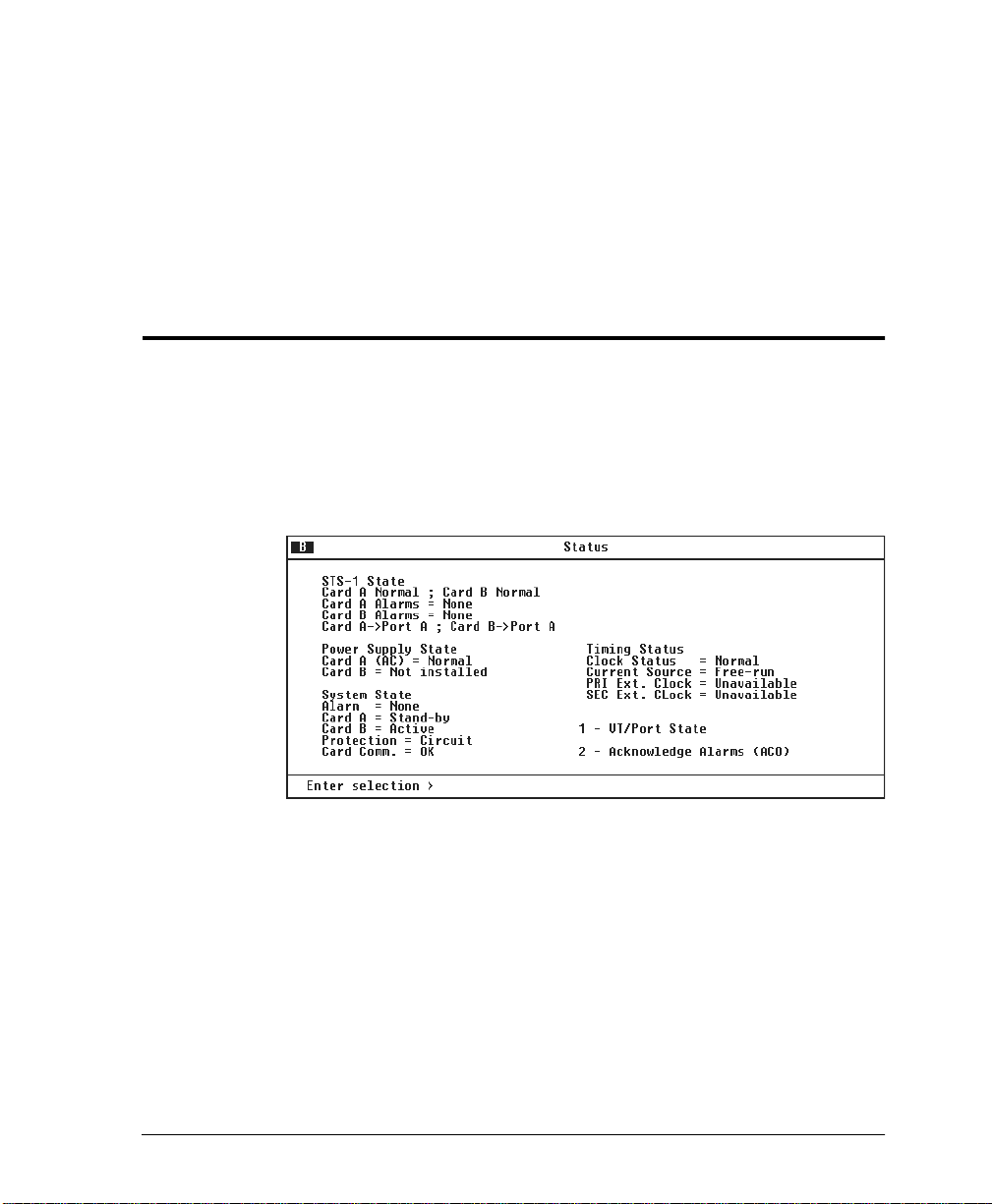
Chapter 4
Status
TATUS
V iew MX28 00 ST S-1 st at us inf or ma tion by sel ecting
AIN
the
M
ENU
M
(see Figure 4-1). The information for the
STS-1, VT/Port lines, power supplies, and controller cards is
provided.
Figure 4-1. Status Menu
S
from
61200659L1-1 MX2800 STS-1 User Manual 4-1
Page 92

Chapter 4. Status
STS-1 STATE
Displays the current state of the STS-1. The following sections
describe the STS-1 status fields in detail.
Card A
Displays the current condition of the network. Possible conditions
are listed in the following chart:
Condition Description
Normal The MX2800 STS-1 is ready to pass data.
Alarm The unit is currently receiving an alarm indication.
In Test The unit is currently in test mode. See Chapter 6,
Card A/Card B Alarms
Alarm types are discussed in the following
section,
Diagnostics
Card A/Card B Alarms
for information on the test type.
.
This field displays the current alarm condition of the
MX2800 STS-1. Possible conditions are given in the following
chart:
Condition Description
Normal No alarms are currently being received.
LOS (Loss of Signal)
The controller card has lost the network receive
signal.
LOF (Loss of Framing)
The controller card detects a framing loss from the
network.
LOP (Loss of Pointer)
The controller card is unable to detect a valid
pointer in the receive signal.
4-2 MX2800 STS-1 User Manual 61200659L1-1
Page 93

Condition Description
LOMF (Loss of Multiframe)
The controller card detects loss of H4 multiframe
from the network.
AIS-L (Line Alarm Indication Signal)
The controller card is receiving a line alarm
indication signal. The Section Terminating
Equipment generates AIS-L after detecting LOS
or LOF.
AIS-P (Path Alarm Indication Signal)
The controller card is receiving a path alarm
indication signal. AIS-P is defined as all ones in
bytes H1, H2, and H3 as well as all ones in the
entire STS synchronous payload envelope.
RFI-L (Line Remote Failure Indication)
The controller card is receiving a line remote
failure indication. RFI-L is declared when the
incoming line remote defect indication (RDI-L,
“110” pattern in bits 6, 7, and 8 of the K2 line
overhead byte) lasts for 2.5 +/- 0.5 seconds.
Chapter 4. Status
RFI-P (Path Remote Failure Indication)
The controller card is receivinga path remote
failure indication. RFI-P is declared when the
incoming path remote defect indication (RDI-P, “1”
in bit 5 of the G1 path overhead byte for
contiguous frames) lasts for 2.5 +/- 0.5 seconds.
SLM-P (Path Signal Lavel Mismatch)
The controller card is detecting a signal label
mismatch. A received signal label is mismatched
if it does not equal the locally provisioned value or
the value “equipped non-specific”.
UEQ-P (Path Unequipped)
The controller card detects that the path is
unequipped. The path is unequipped if it is not
provisioned. Byte C2 of the STS path overhead is
set to zero.
61200659L1-1 MX2800 STS-1 User Manual 4-3
Page 94

Chapter 4. Status
Condition Description
XCV (Excessive Code Violations)
TLOS (Transmit Loss of Signal)
Network Port Mapping
This entry contains a description of the mapping between network
ports and controller cards. In a redundant system with circuit
protection the following is displayed:
Card A Port A | Card B Port A
In a redundant system with network protection the following is
displayed:
The controller is receiving excessive code
violations exceeding the threshold set by the user
XCV Threshold
(see
The contoller card’s transmitter has failed.
on page 3-12).
Card A Port A | Card B
Port B
OR
Card A Port B | Card B
4-4 MX2800 STS-1 User Manual 61200659L1-1
Port A
Page 95

POWER SUPPLY STATE
This field indicat es which t ypes of p ower suppli es are install ed (AC
or DC) in Card A and Card B and gives their current state.
Condition Description
Normal The power supply is fully operational.
Error The controller card cann o t co mm un i ca t e with the
Power Low The power supply output level is abnormally low.
Power Fail The power supply input power is lost.
Charger Fail The battery backup charger has failed or has lost
Battery Low The battery backup has reached a critical energy
Temp High The power supply card temperature is abnormally
Chapter 4. Status
power supply.
its AC connection.
point at which it may be unable to supply the unit
with sufficient power to maintain operation.
high.
Temp Critical The power supply card temperature is so high that
it will soon shut off completely.
SYSTEM STATE
The system state fields display information regarding the two
controller cards. The following sections describe these fields in
detail.
Alarm
This field displays what type (if any) of system alarm is currently
recognized by the unit. The conditi on is disp layed unt il it clea rs up,
61200659L1-1 MX2800 STS-1 User Manual 4-5
Page 96

Chapter 4. Status
with the exception of the
manually).
WITCHED
S
condition (which is cleared
To clear the
(ACO)
ACO Buttons on page 2-12 and Acknowledge Alarms (ACO) on
page 4-12 for more information. Possible alarm types are listed in
the followin g chart:
Condition Description
Supply Failure A power supply card has failed.
Card Failure A controller card is not passing data.
Excessive
Switches
Switched A card switch has occurred.
Card A/Card B
These fields display the current state of the two controller cards.
Possible states for the controller cards are listed in the following
chart:
Condition Description
WITCHED
S
or push the
CKNOWLEDGE ALARMS
condition, select
ACO
button on the front panel. See the sections
AX SWITCHING THRESHOLD
M
The
exceeded. See
3-6.
A
has been
Max. Switch Threshol d
on page
Not Installed No controller card is installed in this slot.
Stand By The controller card is ready to pass data, but is
currently acting as a backup card.
Active The controller card is acting as the primary card.
Failure The controller card has failed and needs to be
replaced.
4-6 MX2800 STS-1 User Manual 61200659L1-1
Page 97

Protection
Chapter 4. Status
This field lists the type of protection mode currently active.
Possible states are listed in the following chart:
Condition Description
Network Both controller cards are installed and everything is
functioning properly. The unit is in full Network
Protection Mode.
Circuit Unit is in Circuit Protection Mode and everything is
functioning properly,
or
unit is in Network Protection Mode and a failure on
the network has occurred.
None One controller card is installed,
or
the unit is in Circuit Protection Mode and the
secondary card has failed.
For more information on the different types of Protection Modes, see
Chapter 7, Circuit and Network Redundancy.
Card Comm
This field displays the current state of the communication link
between the two controller cards.
AILURE
communicating;
F
indicates that the cards are not able to
communicate with each other. If there is only one card installed,
EDUNDANT
NON-R
61200659L1-1 MX2800 STS-1 User Manual 4-7
is displayed.
OK
indicates that the cards are
Page 98

Chapter 4. Status
TIMING STATUS
The following entries describe the state of the transmit timing
subsystem, including the status of the selected reference clock(s),
availability and status of the external clock sources, timing
acquisition status, and internal clock failures.
Clock Status
This entry describes the condition of the clock synchronization
circuitry. The clock status can be any of the following values:
N
•
R
•
recovering from a fault.
L
•
invalid
OUT OF R
•
track the reference source.
OUT OF L
•
lock to the reference source.
ORMAL
– clock synchronization is operating normally.
ECOVERING
OSS OF SOURCE
– clock synchronization is in the process of
ANGE
– the clock synchronization circuit is unable to
OCK
– the clock synchronization circuit is unable to
– the reference clock source has become
Current Source
Indicates the source of the clock. The values for the clock source
are:
OOP
•L
•
•
•F
4-8 MX2800 STS-1 User Manual 61200659L1-1
–
indicates that timing is currentl y being de rived fr om the
STS-1 receive signal.
PRI EXT
– indicates that timing is currently being derived from
the source assigned to the primary external clock source.
XT
SEC E
– indicates that t iming is cur rently b eing deri ved from
the source assigned to the secondary external clock source.
REE-RUN
– indicates that transmit timing is currently being
derived from an internal +/-20 ppm (Stratum 4) SONET
minimum clock source.
Page 99

•H
PRI Ext. Clock
The PRI EXT Clock alarms indicate when a failure condition is
encountered on the PRImary clock source (if configured). The
possible values for this alarm are:
•D
•N
•A
•LOS/AIS –
•F
•U
Chapter 4. Status
OLDOVER
– indicates that a failure in the select ed clock sourc
has occurred and the unit has entered hold-over mode. In this
mode, the last known good clock reference frequency will be
held within 4.1 ppm for a minimum of 24 hours.
ISABLED
–
indicates that the selected clock has been disabled
by the user and will not be used.
ORMAL
–
indicates that the clock source is currently being
used a the timing reference.
VAILABLE
–
indicates that the clock source is available to be
used as a tim ing source if a failure of the current source occurs.
indicates that the clock source is not vali d du e t o a n
LOS or AIS condition.
AIL
–
indicates that an intern al hardware failure on the unit
prevents the clock source from being used.
NAVAILABLE
– indicates that the user has specified a T1/E1
port to be used as an external clock source, but the port has not
been enabled.
SEC Ext. Clock
The SEC EXT Clock alarms indicate when a failure condition is
encountered on the SECondary clock source (if configured). The
possible values for this alarm are:
ISABLED
•D
by the user and will not be used.
ORMAL
•N
used a the timing reference.
VAILABLE
•A
used as a tim ing source if a failure of the current source occurs.
61200659L1-1 MX2800 STS-1 User Manual 4-9
–
indicates that the selected clock has been disabled
–
indicates that the clock source is currently being
–
indicates that the clock source is available to be
Page 100

Chapter 4. Status
• LOS/AIS –
LOS or AIS condition.
•F
prevents the clock source from being used.
•U
port to be used as an external clock source, but the port has not
been enabled.
VT/PORT STATE
This field displays the current alarm condition of the VTs/ports.
Possible conditions are given in the following chart:
VT/Port State
Alarm Description
OFF VT in unequipped and T1/E1 port is disabled.
OK VT/Port is in a normal state.
LOS (T1/E1 Loss of Signal)
CAIS (Carrier Side AIS)
indicates that the clock source is not vali d du e t o a n
AIL
–
indicates that an internal hardware failure on the unit
NAVAILABLE
– indicates that the user has specified a T1/E1
The unit has lost the receive signal on a T1/E1.
The T1 is receiving all ones from the STS side
of the network.
LAIS (Loop Side AIS)
The T1 is receiving all ones from the DSX-1
interface.
XCV (T1/E1 Excessive Code Violations)
The controller card is receiving excessive code
violations, exceeding the threshold set by the
user (see
4-10 MX2800 STS-1 User Manual 61200659L1-1
XCV Threshold
on page 3-12).
 Loading...