

Page 1

NetVanta 3200/3300/3400 Series Routers
Hardware Installation Guide
1203860G1 NetVanta 3200
1203870G1 NetVanta 3205 (AC Version)
1203980G1 NetVanta 3205 (DC Version)
1202880E1 NetVanta 3305
1202820G1 NetVanta 3430
1200821E1 NetVanta 3448
1200823G1 NetVanta 3450
1200824G1 NetVanta 3458
1200861L1 NetVanta 56K/64K Network Interface Module
1202862L1 NetVanta T1/FT1 Network Interface Module
1200862L2#NEBS NetVanta T1/FT1 NEBS Network Interface Module
1202863L1 NetVanta T1/FT1 + DSX-1 Network Interface Module
1202872L1 NetVanta Dual T1 Network Interface Module
1200868E1/L1 NetVanta E1/FE1 Network Interface Module
1200878E1/L1 NetVanta E1/FE1 + G.703 Network Interface Module
1200866E1 NetVanta Serial Network Interface Module
1200936E1 NetVanta SHDSL Network Interface Module, Annex A
1200937E1 NetVanta SHDSL Network Interface Module, Annex B
1202869E1 NetVanta ADSL Network Interface Module, Annex A
1202889E1 NetVanta ADSL Network Interface Module, Annex B
1702803F1 USB WWAN Network Interface Module (NetVanta 3305/3430/3448/3450/3458)
1200864L1 NetVanta Analog Modem Dial Backup Interface Module
1200865L1 NetVanta ISDN BRI Dial Backup Interface Module
1200875L1 NetVanta ISDN S/T Dial Backup Interface Module
4200825E1#120 Octal PoE Upgrade Bundle (Module and 120 VDC Power Supply) (NetVanta 3448/3458)
4200825E1#240 Octal PoE Upgrade Bundle (Module and 240 VDC Power Supply) (NetVanta 3448/3458)
1950860G2 Enhanced Feature Pack Software for IPsec VPN Upgrade (NetVanta 3200/3205/3305)
4200368E1/L1 Enhanced Feature Pack (Hardware and Software) for IPsec VPN Upgrade (NetVanta 3305)
1200819E1
1200827E1 NetVanta 3430/3448 Rackmount Kit
CompactFlash
®
1 GB (NetVanta 3430/3448 only)
61200860L1-34AB
October 2012
Page 2

Trademarks NetVanta 3200/3300/3400 Series
Trademarks
Any brand names and product names included in this manual are trademarks, registered trademarks, or
trade names of their respective holders.
To the Holder of the Manual
The contents of this manual are current as of th e date of publication. ADTRAN reserves the right to change
the contents without prior notice.
In no event will ADTRAN be liable for any special, incidental, or consequential damages or for
commercial losses even if ADTRAN has been advised thereof as a result of issue of this publication.
Software Licensing Agreement
Each ADTRAN product contains a single license for ADTRAN-supplied software. Pursuant to the
Licensing Agreement, you may: (a) use the software on the purchased ADTRAN device only and (b) keep
a copy of the software for backup purposes. This Agreement covers all software installed on the system, as
well as any software available on the ADTRAN website. In addition, certain ADTRAN systems may
contain additional conditions for obtaining software upgrades.
Changes or modifications to this unit not expressly approved by the party responsible for
compliance could void the user’s authority to operate the equipment.
901 Explorer Boulevard
P.O. Box 140000
Huntsville, AL 35814-4000
Phone: (256) 963-8000
Copyright © 2012 ADTRAN, Inc.
All Rights Reserved.
Printed in U.S.A.
2 Copyright © 2012 ADTRAN, Inc. 61200860L1-34AB
Page 3

NetVanta 3200/3300/3400 Series Conventions
Conventions
Notes provide additional useful information.
Cautions signify information that could prevent service interruption or damage to the
equipment.
Warnings provide information that could prevent injury or endangerment to human
life.
61200860L1-34AB Copyright © 2012 ADTRAN, Inc. 3
Page 4
Safety Instructions NetVanta 3200/3300/3400 Series
Safety Instructions
When using your telephone equipment, please follow these basic safety precautions to reduce the risk of
fire, electrical shock, or personal injury:
1. Do not use this product near water, such as a bathtub, wash bowl, kitchen sink, laundry tub, in a
wet basement, or near a swimming pool.
2. Avoid using a telephone (other than a cordless type) during an electrical storm. There is a remote
risk of shock from lightning.
3. Do not use the telephone to report a gas leak in the vicinity of the leak.
4. Use only the power cord, power supply, and batteries indicated in the manual. Do not dispose of
batteries in a fire. They may explode. Check with local codes for special disposal instructions.
5. The socket-outlet shall be installed near the equipment and shall be easily accessible.
If any of the following conditions occur, unplug the product from the electrical outlet and replace the part
or contact your qualified service personnel:
1. The power cable, extension cable, or plug is damaged.
2. An object has fallen into the product.
3. The product has been exposed to water.
4. The product has been dropped or damaged.
5. The product does not operate correctly when you follow the operating instructions.
These units contain no user-serviceable parts. They should only be serviced by qualified
service personnel.
This equipment incorporates double pole/neutral fusing. If the neutral fuse opens and the
line fuse does not open, voltage could still be present in the unit.
Additional safety guidelines, such as Waste Electrical and Electronic Equipment (WEEE),
are given in the document NetVanta Safety and Regulatory Information
https://supportforums.adtran.com
.
available at
Save These Important Safety Instructions
4 Copyright © 2012 ADTRAN, Inc. 61200860L1-34AB
Page 5

NetVanta 3200/3300/3400 Series FCC-Required Information
FCC-Required Information
FCC regulations require that the following information be provided in this manual:
1. This equipment complies with Part 68 of Federal Communications Commission (FCC) rules and
requirements adopted by America’s Carriers Telecommunications Association (ACTA). Each
registered interface has a label that contains, among other information, a product identifier in the
format US:AAAEQ##TXXXX. If requested, provide this information to the telephone company.
2. If this equipment causes harm to the telephone network, the telephone company may temporarily
discontinue service. If possible, advance notification is given; otherwise, notification is given as
soon as possible. The telephone company will advise the customer of the right to file a complaint
with the FCC.
3. The telephone company may make changes in its facilities, equipment, operations, or procedures
that could affect the proper operation of this equipment. Advance notification and the opportunity
to maintain uninterrupted service are given.
4. If experiencing difficulty with this equipment, please contact ADTRAN for repair and warranty
information. The telephone company may require this equipment to be disconnected from the
network until the problem is corrected, or it is certain the equipment is not malfunctioning.
5. This unit contains no user-serviceable parts.
6. This equipment is designed to connect to the telephone network or premises wiring using an
FCC-compatible modular jack, which is compliant with Part 68 and requirements adopted by
ACTA.
7. The following information may be required when applying to the local telephone company for
leased line facilities:
Part Number Registration Number Service Type REN/SOC FIC USOC
1200861L1 US: HDCDENAN1200861L1 56 kbps Digital Interface
64 kbps Digital Interface
1202862L1 US: HDCDENAN1202863L1 1.544 Mbps - SF
1202863L1
1200872L1 US: HDCDENAN1200872L1
1200864L1 US: HDCMM04A1200864L1 Analog Loop Start 0.4A/9.0Y 02LS2 RJ-11C
1200865L1 US: HDCDENAN1200865L1 Basic Rate ISDN 6.0F 02IS5 RJ-49C
1202869E1 US: HDCDL01A1200869L1 ADSL, ADSL2, ADSL2+ Modem 0.1A Metallic RJ-11C
1.544 Mbps - SF and B8ZS
1.544 Mbps - ESF
1.544 Mbps - ESF and B8ZS
6.0F 04DU5-56
04DU5-64
04DU9-BN
6.0N
04DU9-DN
04DU9-1KN
04DU9-1SN
RJ-48S
RJ-48C
8. The ringer equivalency number (REN) is useful in determining the quantity of devices you may
connect to your telephone line and still have all of those devices ring when your number is called.
In most areas, the sum of the RENs of all devices should not exceed five. To be certain of the
number of devices you may connect to your line as determined by the REN, call your telephone
company to determine the maximum REN for your calling area.
9. This equipment may not be used on coin service provided by the telephone company. Connection
to party lines is subject to state tariffs. Contact your state public utility commission or corporation
commission for information.
61200860L1-34AB Copyright © 2012 ADTRAN, Inc. 5
Page 6

FCC Radio Frequency Interference Statement NetVanta 3200/3300/3400 Series
FCC Radio Frequency Interference Statement
This equipment has been tested and found to comply with the limits for a Class A digital device, pursuant
to Part 15 of the FCC rules. These limits are designed to provide reasonable protection against harmful
interference when the equipment is operated in a commercial environment. This equipment generates,
uses, and can radiate radio frequency energy and, if not installed and used in accordance with the
instruction manual, may cause harmful interference to radio frequencies. Operation of this equipment in a
residential area is likely to cause harmful interference in which case the user will be required to correct the
interference at his own expense.
Electromagnetic Compatibility (EMC) Table
NetVanta Module P/N and Name NetVanta 3200
(1203860G1)
1200861L1 56K/64K NIM FCC Part 15 Class A
1202862L1 T1/FT1 NIM FCC Part 15 Class B
1200862L2#NEBS T1/FT1 NEBS NIM N/A N/A FCC Part 15 Class A
1202863L1 T1/FT1 + DSX-1 NIM FCC Part 15 Class B
1202872L1 Dual T1 NIM FCC Part 15 Class B
1200868E1/L1 E1/FE1 NIM FCC Part 15 Class B
1200878E1/L1 E1/FE1 + G.703 NIM FCC Part 15 Class B
1200866E1 Serial NIM FCC Part 15 Class B
1200936E1
1200937E1
1202869E1
1202889E1
1702803F1 USB WWAN NIM N/A
1200864L1
1200865L1
1200875L1
1202368L1 VPN Accelerator Card N/A N/A N/A FCC Part 15 Class A
SHDSL NIM, Annex A
SHDSL NIM, Annex B
ADSL NIM, Annex A
ADSL NIM, Annex B
Analog Modem DIM
ISDN BRI DIM
ISDN S/T DIM
EN 55022 Class A
EN 55022 Class B
EN 55022 Class B
EN 55022 Class B
EN 55022 Class B
EN 55024
EN 55022 Class B
EN 55024
EN 55022 Class B
EN 55024
FCC Part 15 Class B
EN 55022 Class B
EN 55024
FCC Part 15 Class B
EN 55022 Class B
EN 55024
FCC Part 15 Class B
EN 55022 Class B
EN 55024
NetVanta 3205 AC
(1203870G1)
NetVanta 3430 (1202820G1)
NetVanta 3448 (1200821E1)
NetVanta 3450 (1200823G1)
NetVanta 3458 (1200824G1)
FCC Part 15 Class A
EN 55022 Class A
FCC Part 15 Class A
EN 55022 Class A
FCC Part 15 Class A
EN 55022 Class A
FCC Part 15 Class A
EN 55022 Class A
FCC Part 15 Class A
EN 55022 Class A
EN 55024
FCC Part 15 Class A
EN 55022 Class A
EN 55024
FCC Part 15 Class A
EN 55022 Class A
EN 55024
FCC Part 15 Class A
EN 55022 Class A
EN 55024
FCC Part 15 Class A
EN 55022 Class A
EN 55024
FCC Part 15 Class A
EN 55022 Class A
EN 55024
FCC Part 15 Class A
EN 55022 Class A
EN 55024
NetVanta 3205 DC
(1203980G1)
FCC Part 15 Class A
EN 55022 Class A
FCC Part 15 Class A
EN 55022 Class A
EN 55022 Class A
GR-1089-CORE Sec. 2 and 3
FCC Part 15 Class A
EN 55022 Class A
FCC Part 15 Class A
EN 55022 Class A
FCC Part 15 Class A
EN 55022 Class A
EN 55024
FCC Part 15 Class A
EN 55022 Class A
EN 55024
FCC Part 15 Class A
EN 55022 Class A
EN 55024
FCC Part 15 Class A
EN 55022 Class A
EN 55024
FCC Part 15 Class A
EN 55022 Class A
EN 55024
FCC Part 15 Class A
EN 55022 Class A
EN 55024
FCC Part 15 Class A
EN 55022 Class A
EN 55024
NetVanta 3305
(1202880E1)
FCC Part 15 Class A
EN 55022 Class A
FCC Part 15 Class A
EN 55022 Class A
N/A
FCC Part 15 Class A
EN 55022 Class A
FCC Part 15 Class A
EN 55022 Class A
FCC Part 15 Class A
EN 55022 Class A
EN 55024
FCC Part 15 Class A
EN 55022 Class A
EN 55024
FCC Part 15 Class A
EN 55022 Class A
EN 55024
FCC Part 15 Class A
EN 55022 Class A
EN 55024
FCC Part 15 Class A
EN 55022 Class A
EN 55024
FCC Part 15 Class A
EN 55022 Class A
EN 55024
FCC Part 15 Class A
EN 55022 Class A
EN 55024
EN 55022 Class A
EN 55024
6 Copyright © 2012 ADTRAN, Inc. 61200860L1-34AB
Page 7

NetVanta 3200/3300/3400 Series Industry Canada Compliance Information
Industry Canada Compliance Information
Notice: The Industry Canada label applied to the product (identified by the Industry Canada logo or the
“IC:” in front of the certification/registration number) signifies that the Industry Canada technical
specifications were met.
Notice: The REN for this terminal equipment is supplied in the documentation or on the product
labeling/markings. The REN assigned to each terminal device indicates the maximum number of terminals
that can be connected to a telephone interface. The termination on an interface may consist of any
combination of devices subject only to the requirement that the sum of the RENs of all the devices should
not exceed five (5).
Canadian Emissions Requirements
This digital apparatus does not exceed the Class A limits for radio noise emissions from digital apparatus
as set out in the interference-causing equipment standard entitled “Digital Apparatus,” ICES-003 of the
Department of Communications.
Cet appareil numérique respecte les limites de bruits radioelectriques applicables aux appareils numériques
de Class A prescrites dans la norme sur le materiel brouilleur: “Appareils Numériques,” NMB-003 edictee
par le ministre des Communications.
Toll Fraud Liability
Be advised that certain security risks are inherent in the use of any telecommunications or networking
equipment, including but not limited to, toll fraud, Denial of Service (DoS) attacks, loss or theft of data, and the
unauthorized or illegal use of said equipment. ADTRAN OFFERS NO W ARRANTIES, EITHER
EXPRESSED OR IMPLIED, REGARDING THE PREVENTION, DETECTION, OR DETERRENCE OF
TOLL FRAUD, NETWORKING ATTACKS, OR UNAUTHORIZED, ILLEGAL, OR IMPROPER USE OF
ADTRAN EQUIPMENT OR SOFTWARE. THEREFORE, ADTRAN IS NOT LIABLE FOR ANY LOSSES
OR DAMAGES RESULTING FROM SUCH FRAUD, ATTACK, OR IMPROPER USE, INCLUDING, BUT
NOT LIMITED TO, HUMAN AND DATA PRIVACY, INTELLECTUAL PROPERTY, MATERIAL
ASSETS, FINANCIAL RESOURCES, LABOR AND LEGAL COSTS. Ultimately, the responsibility for
securing your telecommunication and networking equipment rests with you, and you are encouraged to review
documentation regarding available security measures, their configuration and implementation, and to test such
features as is necessary for your network.
Service and Warranty
For information on the service and warranty of ADTRAN products, visit the Support section of the
ADTRAN website at http://www.adtran.com
.
61200860L1-34AB Copyright © 2012 ADTRAN, Inc. 7
Page 8

Service and Warranty NetVanta 3200/3300/3400 Series
8 Copyright © 2012 ADTRAN, Inc. 61200860L1-34AB
Page 9

Table of Contents
Introduction . . . . . . . . . . . . . . . . . . . . . . . . . . . . . . . . . . . . . . . . . . . . . . . . . . . . . . . . . . . . . . . . . . . . . . . 15
Physical Descriptions . . . . . . . . . . . . . . . . . . . . . . . . . . . . . . . . . . . . . . . . . . . . . . . . . . . . . . . . . . . . . . . 16
NetVanta 3200 . . . . . . . . . . . . . . . . . . . . . . . . . . . . . . . . . . . . . . . . . . . . . . . . . . . . . . . . . . . . . . . . . . 16
NetVanta 3200 Features and Specifications . . . . . . . . . . . . . . . . . . . . . . . . . . . . . . . . . . . . . . . . 16
NetVanta 3200 Shipping Contents . . . . . . . . . . . . . . . . . . . . . . . . . . . . . . . . . . . . . . . . . . . . . . . . 17
NetVanta 3200 Front Panel Design . . . . . . . . . . . . . . . . . . . . . . . . . . . . . . . . . . . . . . . . . . . . . . . 18
NetVanta 3200 Rear Panel Design . . . . . . . . . . . . . . . . . . . . . . . . . . . . . . . . . . . . . . . . . . . . . . . 18
NetVanta 3205 . . . . . . . . . . . . . . . . . . . . . . . . . . . . . . . . . . . . . . . . . . . . . . . . . . . . . . . . . . . . . . . . . . 19
NetVanta 3205 Features and Specifications . . . . . . . . . . . . . . . . . . . . . . . . . . . . . . . . . . . . . . . . 19
NetVanta 3205 Shipping Contents . . . . . . . . . . . . . . . . . . . . . . . . . . . . . . . . . . . . . . . . . . . . . . . . 20
NetVanta 3205 Front Panel Design . . . . . . . . . . . . . . . . . . . . . . . . . . . . . . . . . . . . . . . . . . . . . . . 21
NetVanta 3205 Rear Panel Design . . . . . . . . . . . . . . . . . . . . . . . . . . . . . . . . . . . . . . . . . . . . . . . 21
NetVanta 3305 . . . . . . . . . . . . . . . . . . . . . . . . . . . . . . . . . . . . . . . . . . . . . . . . . . . . . . . . . . . . . . . . . . 22
NetVanta 3305 Features and Specifications . . . . . . . . . . . . . . . . . . . . . . . . . . . . . . . . . . . . . . . . 22
NetVanta 3305 Shipping Contents . . . . . . . . . . . . . . . . . . . . . . . . . . . . . . . . . . . . . . . . . . . . . . . . 24
NetVanta 3305 Front Panel Design . . . . . . . . . . . . . . . . . . . . . . . . . . . . . . . . . . . . . . . . . . . . . . . 24
NetVanta 3305 Rear Panel Design . . . . . . . . . . . . . . . . . . . . . . . . . . . . . . . . . . . . . . . . . . . . . . . 24
NetVanta 3430 . . . . . . . . . . . . . . . . . . . . . . . . . . . . . . . . . . . . . . . . . . . . . . . . . . . . . . . . . . . . . . . . . . 25
NetVanta 3430 Features and Specifications . . . . . . . . . . . . . . . . . . . . . . . . . . . . . . . . . . . . . . . . 25
NetVanta 3430 Shipping Contents . . . . . . . . . . . . . . . . . . . . . . . . . . . . . . . . . . . . . . . . . . . . . . . . 27
NetVanta 3430 Front Panel Design . . . . . . . . . . . . . . . . . . . . . . . . . . . . . . . . . . . . . . . . . . . . . . . 28
NetVanta 3430 Rear Panel Design . . . . . . . . . . . . . . . . . . . . . . . . . . . . . . . . . . . . . . . . . . . . . . . 28
NetVanta 3448 . . . . . . . . . . . . . . . . . . . . . . . . . . . . . . . . . . . . . . . . . . . . . . . . . . . . . . . . . . . . . . . . . . 29
NetVanta 3448 Features and Specifications . . . . . . . . . . . . . . . . . . . . . . . . . . . . . . . . . . . . . . . . 29
NetVanta 3448 Shipping Contents . . . . . . . . . . . . . . . . . . . . . . . . . . . . . . . . . . . . . . . . . . . . . . . . 30
NetVanta 3448 Front Panel Design . . . . . . . . . . . . . . . . . . . . . . . . . . . . . . . . . . . . . . . . . . . . . . . 31
NetVanta 3448 Rear Panel Design . . . . . . . . . . . . . . . . . . . . . . . . . . . . . . . . . . . . . . . . . . . . . . . 32
NetVanta 3450 . . . . . . . . . . . . . . . . . . . . . . . . . . . . . . . . . . . . . . . . . . . . . . . . . . . . . . . . . . . . . . . . . . 32
NetVanta 3450 Features and Specifications . . . . . . . . . . . . . . . . . . . . . . . . . . . . . . . . . . . . . . . . 33
NetVanta 3450 Shipping Contents . . . . . . . . . . . . . . . . . . . . . . . . . . . . . . . . . . . . . . . . . . . . . . . . 34
NetVanta 3450 Front Panel Design . . . . . . . . . . . . . . . . . . . . . . . . . . . . . . . . . . . . . . . . . . . . . . . 35
NetVanta 3450 Rear Panel Design . . . . . . . . . . . . . . . . . . . . . . . . . . . . . . . . . . . . . . . . . . . . . . . 35
NetVanta 3458 . . . . . . . . . . . . . . . . . . . . . . . . . . . . . . . . . . . . . . . . . . . . . . . . . . . . . . . . . . . . . . . . . . 36
NetVanta 3458 Features and Specifications . . . . . . . . . . . . . . . . . . . . . . . . . . . . . . . . . . . . . . . . 36
NetVanta 3458 Shipping Contents . . . . . . . . . . . . . . . . . . . . . . . . . . . . . . . . . . . . . . . . . . . . . . . . 37
NetVanta 3458 Front Panel Design . . . . . . . . . . . . . . . . . . . . . . . . . . . . . . . . . . . . . . . . . . . . . . . 38
NetVanta 3458 Rear Panel Design . . . . . . . . . . . . . . . . . . . . . . . . . . . . . . . . . . . . . . . . . . . . . . . 39
NetVanta 3000 Series Front Panel LEDs . . . . . . . . . . . . . . . . . . . . . . . . . . . . . . . . . . . . . . . . . . . . . . 40
Option Modules . . . . . . . . . . . . . . . . . . . . . . . . . . . . . . . . . . . . . . . . . . . . . . . . . . . . . . . . . . . . . . . . . . . . 41
Option Module Shipping Contents . . . . . . . . . . . . . . . . . . . . . . . . . . . . . . . . . . . . . . . . . . . . . . . . . . . 42
Network Interface Modules . . . . . . . . . . . . . . . . . . . . . . . . . . . . . . . . . . . . . . . . . . . . . . . . . . . . . . . . 45
NetVanta 56K/64K NIM (P/N 1200861L1) . . . . . . . . . . . . . . . . . . . . . . . . . . . . . . . . . . . . . . . . . . 45
NetVanta T1/FT1 NIM (P/N 1202862L1) . . . . . . . . . . . . . . . . . . . . . . . . . . . . . . . . . . . . . . . . . . . 46
NetVanta T1/FT1 NEBS NIM (P/N 1200862L2#NEBS) . . . . . . . . . . . . . . . . . . . . . . . . . . . . . . . 47
NetVanta T1/FT1 + DSX-1 NIM (P/N 1202863L1) . . . . . . . . . . . . . . . . . . . . . . . . . . . . . . . . . . . 48
NetVanta Dual T1 NIM (P/N 1200872L1/1202872L1) . . . . . . . . . . . . . . . . . . . . . . . . . . . . . . . . . 49
NetVanta E1/FE1 NIM (P/N 1200868E1/L1) . . . . . . . . . . . . . . . . . . . . . . . . . . . . . . . . . . . . . . . . 50
NetVanta E1/FE1 + G.703 NIM (P/N 1200878E1/L1) . . . . . . . . . . . . . . . . . . . . . . . . . . . . . . . . . 51
NetVanta Serial NIM (P/N 1200866E1) . . . . . . . . . . . . . . . . . . . . . . . . . . . . . . . . . . . . . . . . . . . . 52
NetVanta SHDSL NIM, Annex A (P/N 1200936E1) . . . . . . . . . . . . . . . . . . . . . . . . . . . . . . . . . . . 53
61200860L1-34AB Copyright © 2012 ADTRAN, Inc. 9
Page 10

Table of Contents NetVanta 3200/3300/3400 Series
NetVanta SHDSL NIM, Annex B (P/N 1200937E1) . . . . . . . . . . . . . . . . . . . . . . . . . . . . . . . . . . . 54
NetVanta ADSL NIM, Annex A (P/N 1202869E1) . . . . . . . . . . . . . . . . . . . . . . . . . . . . . . . . . . . . 55
NetVanta ADSL NIM, Annex B (P/N 1202889E1) . . . . . . . . . . . . . . . . . . . . . . . . . . . . . . . . . . . . 56
NetVanta USB WWAN NIM (P/N 1702803F1) . . . . . . . . . . . . . . . . . . . . . . . . . . . . . . . . . . . . . . 57
Dial Backup Interface Modules . . . . . . . . . . . . . . . . . . . . . . . . . . . . . . . . . . . . . . . . . . . . . . . . . . . . . 58
NetVanta Analog Modem DIM (P/N 1200864L1) . . . . . . . . . . . . . . . . . . . . . . . . . . . . . . . . . . . . . 58
NetVanta ISDN BRI DIM (P/N 1200865L1) . . . . . . . . . . . . . . . . . . . . . . . . . . . . . . . . . . . . . . . . . 59
NetVanta ISDN S/T DIM (P/N 1200875L1) . . . . . . . . . . . . . . . . . . . . . . . . . . . . . . . . . . . . . . . . . 60
Unit Installation . . . . . . . . . . . . . . . . . . . . . . . . . . . . . . . . . . . . . . . . . . . . . . . . . . . . . . . . . . . . . . . . . . . . 61
Tools Required . . . . . . . . . . . . . . . . . . . . . . . . . . . . . . . . . . . . . . . . . . . . . . . . . . . . . . . . . . . . . . . . . . 61
Mounting Options . . . . . . . . . . . . . . . . . . . . . . . . . . . . . . . . . . . . . . . . . . . . . . . . . . . . . . . . . . . . . . . . 62
Rack Mounting NetVanta 3205, NetVanta 3305, NetVanta 3430, NetVanta 3448, NetVanta 3450,
and NetVanta 3458. . . . . . . . . . . . . . . . . . . . . . . . . . . . . . . . . . . . . . . . . . . . . . . . . . . . . . . . . . . . 62
Wall Mounting NetVanta 3200/3300/3400 Series. . . . . . . . . . . . . . . . . . . . . . . . . . . . . . . . . . . . . 63
Wall Mounting the NetVanta PoE Power Supply . . . . . . . . . . . . . . . . . . . . . . . . . . . . . . . . . . . . . 67
Supplying Power to the Unit . . . . . . . . . . . . . . . . . . . . . . . . . . . . . . . . . . . . . . . . . . . . . . . . . . . . . . . . 69
Powering the NetVanta 3200 . . . . . . . . . . . . . . . . . . . . . . . . . . . . . . . . . . . . . . . . . . . . . . . . . . . . 69
Powering the NetVanta 3205 (AC), NetVanta 3305, NetVanta 3430, NetVanta 3448,
NetVanta 3450, and NetVanta 3458. . . . . . . . . . . . . . . . . . . . . . . . . . . . . . . . . . . . . . . . . . . . . . . 71
Powering the NetVanta with Octal PoE Upgrade . . . . . . . . . . . . . . . . . . . . . . . . . . . . . . . . . . . . . 71
Powering the NetVanta 3205 (DC). . . . . . . . . . . . . . . . . . . . . . . . . . . . . . . . . . . . . . . . . . . . . . . . 72
Installing Dial Backup and Network Interface Modules . . . . . . . . . . . . . . . . . . . . . . . . . . . . . . . . . . . 75
Using a USB Cellular Modem with the NetVanta USB WWAN NIM . . . . . . . . . . . . . . . . . . . . . . . . . 77
Installing the NetVanta VPN Accelerator Card (included in P/N 4200368L1) . . . . . . . . . . . . . . . . . . 78
Installing SODIMM for Expandable Memory . . . . . . . . . . . . . . . . . . . . . . . . . . . . . . . . . . . . . . . . . . . 79
Installing a CompactFlash Card . . . . . . . . . . . . . . . . . . . . . . . . . . . . . . . . . . . . . . . . . . . . . . . . . . . . . 81
Installing the Octal PoE Upgrade Module . . . . . . . . . . . . . . . . . . . . . . . . . . . . . . . . . . . . . . . . . . . . . 82
Appendix A. Connector Pin Definitions . . . . . . . . . . . . . . . . . . . . . . . . . . . . . . . . . . . . . . . . . . . . . . . . 85
10 Copyright © 2012 ADTRAN, Inc. 61200860L1-34AB
Page 11

List of Figures
Figure 1. NetVanta 3200 Front Panel Layout . . . . . . . . . . . . . . . . . . . . . . . . . . . . . . . . . . . . . . . . . . . . 18
Figure 2. NetVanta 3200 Rear Panel Layout . . . . . . . . . . . . . . . . . . . . . . . . . . . . . . . . . . . . . . . . . . . . 18
Figure 3. NetVanta 3205 Front Panel Layout . . . . . . . . . . . . . . . . . . . . . . . . . . . . . . . . . . . . . . . . . . . . 21
Figure 4. NetVanta 3205 (AC version) Rear Panel Layout . . . . . . . . . . . . . . . . . . . . . . . . . . . . . . . . . . 21
Figure 5. NetVanta 3205 (DC version) Rear Panel Layout. . . . . . . . . . . . . . . . . . . . . . . . . . . . . . . . . . 21
Figure 6. NetVanta 3305 Front Panel Layout . . . . . . . . . . . . . . . . . . . . . . . . . . . . . . . . . . . . . . . . . . . . 24
Figure 7. NetVanta 3305 Rear Panel Layout . . . . . . . . . . . . . . . . . . . . . . . . . . . . . . . . . . . . . . . . . . . . 24
Figure 8. NetVanta 3430 (1202820G1) Front Panel Layout . . . . . . . . . . . . . . . . . . . . . . . . . . . . . . . . . 28
Figure 9. NetVanta 3430 (1202820G1) Rear Panel Layout . . . . . . . . . . . . . . . . . . . . . . . . . . . . . . . . . 28
Figure 10. NetVant a 34 48 Fr on t Pan el Layo u t . . . . . . . . . . . . . . . . . . . . . . . . . . . . . . . . . . . . . . . . . . . . 31
Figure 11. NetVanta 3448 Rear Panel Layout . . . . . . . . . . . . . . . . . . . . . . . . . . . . . . . . . . . . . . . . . . . . 32
Figure 12. NetVant a 34 50 Fr on t Pan el Layo u t . . . . . . . . . . . . . . . . . . . . . . . . . . . . . . . . . . . . . . . . . . . . 35
Figure 13. NetVanta 3450 Rear Panel Layout . . . . . . . . . . . . . . . . . . . . . . . . . . . . . . . . . . . . . . . . . . . . 35
Figure 14. NetVant a 34 58 Fr on t Pan el Layo u t . . . . . . . . . . . . . . . . . . . . . . . . . . . . . . . . . . . . . . . . . . . . 38
Figure 15. NetVanta 3458 Rear Panel Layout . . . . . . . . . . . . . . . . . . . . . . . . . . . . . . . . . . . . . . . . . . . . 39
Figure 16. NetVanta 56K/64K NIM . . . . . . . . . . . . . . . . . . . . . . . . . . . . . . . . . . . . . . . . . . . . . . . . . . . . . 45
Figure 17. NetVanta T1/FT1 NIM . . . . . . . . . . . . . . . . . . . . . . . . . . . . . . . . . . . . . . . . . . . . . . . . . . . . . . 46
Figure 18. NetVanta T1/FT1 NEBS NIM . . . . . . . . . . . . . . . . . . . . . . . . . . . . . . . . . . . . . . . . . . . . . . . . . 47
Figure 19. NetVanta T1/FT1 + DSX-1 NIM . . . . . . . . . . . . . . . . . . . . . . . . . . . . . . . . . . . . . . . . . . . . . . . 48
Figure 20. NetVanta Dual T1 NIM. . . . . . . . . . . . . . . . . . . . . . . . . . . . . . . . . . . . . . . . . . . . . . . . . . . . . . 49
Figure 21. NetVanta E1/FE1 NIM . . . . . . . . . . . . . . . . . . . . . . . . . . . . . . . . . . . . . . . . . . . . . . . . . . . . . . 50
Figure 22. NetVanta E1/FE1 + G.703 NIM . . . . . . . . . . . . . . . . . . . . . . . . . . . . . . . . . . . . . . . . . . . . . . . 51
Figure 23. NetVanta Serial NIM . . . . . . . . . . . . . . . . . . . . . . . . . . . . . . . . . . . . . . . . . . . . . . . . . . . . . . . 52
Figure 24. NetVanta SHDSL NIM, Annex A . . . . . . . . . . . . . . . . . . . . . . . . . . . . . . . . . . . . . . . . . . . . . . 53
Figure 25. NetVanta SHDSL NIM, Annex B . . . . . . . . . . . . . . . . . . . . . . . . . . . . . . . . . . . . . . . . . . . . . . 54
Figure 26. NetVanta ADSL NIM, Annex A. . . . . . . . . . . . . . . . . . . . . . . . . . . . . . . . . . . . . . . . . . . . . . . . 55
Figure 27. NetVanta ADSL NIM, Annex B. . . . . . . . . . . . . . . . . . . . . . . . . . . . . . . . . . . . . . . . . . . . . . . . 56
Figure 28. NetVanta USB WWAN NIM . . . . . . . . . . . . . . . . . . . . . . . . . . . . . . . . . . . . . . . . . . . . . . . . . . 57
Figure 29. Wall Mounting the NetVanta 3200 . . . . . . . . . . . . . . . . . . . . . . . . . . . . . . . . . . . . . . . . . . . . . 64
Figure 30. Repositioning the Mounting Bracket for Wall Mounting the NetVanta 3205/3305 . . . . . . . . . 65
Figure 31. Wall Mounting the NetVanta 3430/NetVanta 3448 . . . . . . . . . . . . . . . . . . . . . . . . . . . . . . . . 66
Figure 32. Wall Mounting the NetVanta 3450 and NetVanta 3458 . . . . . . . . . . . . . . . . . . . . . . . . . . . . . 67
Figure 33. Wall Mounting the NetVanta PoE Power Supply . . . . . . . . . . . . . . . . . . . . . . . . . . . . . . . . . . 68
Figure 34. NetVanta 3200 Power Connector . . . . . . . . . . . . . . . . . . . . . . . . . . . . . . . . . . . . . . . . . . . . . 70
Figure 35. NetVanta 3205 DC Power Connection. . . . . . . . . . . . . . . . . . . . . . . . . . . . . . . . . . . . . . . . . . 73
Figure 36. Installing DIMs . . . . . . . . . . . . . . . . . . . . . . . . . . . . . . . . . . . . . . . . . . . . . . . . . . . . . . . . . . . . 75
Figure 37. NIM and DIM Installation . . . . . . . . . . . . . . . . . . . . . . . . . . . . . . . . . . . . . . . . . . . . . . . . . . . . 76
Figure 38. NetVanta VPN Accelerator Card Installation . . . . . . . . . . . . . . . . . . . . . . . . . . . . . . . . . . . . . 78
Figure 39. SODIMM Installation – Keyed Slots. . . . . . . . . . . . . . . . . . . . . . . . . . . . . . . . . . . . . . . . . . . . 80
Figure 40. SODIMM Installation – Applying Pressure. . . . . . . . . . . . . . . . . . . . . . . . . . . . . . . . . . . . . . . 80
Figure 41. SODIMM Installation – Rotating the Module Downward . . . . . . . . . . . . . . . . . . . . . . . . . . . . 80
Figure 42. CompactFlash Card Installation. . . . . . . . . . . . . . . . . . . . . . . . . . . . . . . . . . . . . . . . . . . . . . . 81
Figure 43. NetVanta Octal PoE Upgrade Installation . . . . . . . . . . . . . . . . . . . . . . . . . . . . . . . . . . . . . . . 83
61200860L1-34AB Copyright © 2012 ADTRAN, Inc. 11
Page 12

List of Figures NetVanta 3200/3300/3400 Series
12 Copyright © 2012 ADTRAN, Inc. 61200860L1-34AB
Page 13

List of Tables
Table 1. NetVanta 3000 Series Front Panel LEDs . . . . . . . . . . . . . . . . . . . . . . . . . . . . . . . . . . . . . 40
Table A-1. 10/100Base-T Ethernet Port Pinouts . . . . . . . . . . . . . . . . . . . . . . . . . . . . . . . . . . . . . . . . . 85
Table A-2. CONSOLE Port (DCE) Pinou ts for NetVanta 3200, 3205, 3430, and 3448 . . . . . . . . . . . . 85
Table A-3. CONSOLE Port (DCE) Pinouts for NetVanta 3305. . . . . . . . . . . . . . . . . . . . . . . . . . . . . . . 86
Table A-4. DC Power Supply Connection (NetVanta 3205 DC Version Only). . . . . . . . . . . . . . . . . . . 86
Table A-5. ADSL Connector Pinouts . . . . . . . . . . . . . . . . . . . . . . . . . . . . . . . . . . . . . . . . . . . . . . . . . . 86
Table A-6. WAN-DDS Connector Pinouts . . . . . . . . . . . . . . . . . . . . . . . . . . . . . . . . . . . . . . . . . . . . . . 87
Table A-7. WAN-T1 Connector Pinouts . . . . . . . . . . . . . . . . . . . . . . . . . . . . . . . . . . . . . . . . . . . . . . . . 87
Table A-8. WAN-E1 Connector Pinouts. . . . . . . . . . . . . . . . . . . . . . . . . . . . . . . . . . . . . . . . . . . . . . . . 87
Table A-9. DSX-1 Connector Pinouts. . . . . . . . . . . . . . . . . . . . . . . . . . . . . . . . . . . . . . . . . . . . . . . . . . 88
Table A-10. G.703 Connector Pinouts . . . . . . . . . . . . . . . . . . . . . . . . . . . . . . . . . . . . . . . . . . . . . . . . . . 88
Table A-11. WAN-SHDSL Connector Pinouts . . . . . . . . . . . . . . . . . . . . . . . . . . . . . . . . . . . . . . . . . . . . 88
Table A-12. WAN-ADSL Connector Pinouts . . . . . . . . . . . . . . . . . . . . . . . . . . . . . . . . . . . . . . . . . . . . . 89
Table A-13. USB WWAN Connector Pinouts. . . . . . . . . . . . . . . . . . . . . . . . . . . . . . . . . . . . . . . . . . . . . 89
Table A-14. Serial to Cable Connector Pinouts . . . . . . . . . . . . . . . . . . . . . . . . . . . . . . . . . . . . . . . . . . . 90
Table A-15. Analog Modem and ISDN BRI DBU Connector Pinouts. . . . . . . . . . . . . . . . . . . . . . . . . . . 91
Table A-16. ISDN S/T DBU Connector Pinouts . . . . . . . . . . . . . . . . . . . . . . . . . . . . . . . . . . . . . . . . . . . 91
61200860L1-34AB Copyright © 2012 ADTRAN, Inc. 13
Page 14

List of Tables NetVanta 3200/3300/3400 Series
14 Copyright © 2012 ADTRAN, Inc. 61200860L1-34AB
Page 15

1. INTRODUCTION
The NetVanta 3200/3300/3400 Series includes the NetVanta 3200, NetVanta 3205 (AC or DC powered),
NetVanta 3305, NetVanta 3430, NetVanta 3448, NetVanta 3450, and NetVanta 3458.
In this document, the term NetVanta 3200/3300/3400 Series means all of the units
collectively. If a statement only applies to one particular r outer, the text refers to the r outer
individually.
This hardware installation guide lists the NetVanta 3200/3300/3400 Series units’ physical characteristics
and product specifications, introduces basic functionality, and provides installation instructions.
• Physical Descriptions on page 16
• Option Modules on page 41
• Unit Installatio n on pa ge 61
For additional information on mounting options, suppling power, upgrading memory, and installing a
CompactFlash card, refer to the following sections:
• Mountin g Option s on pa ge 62
• Supplying Power to the Unit on page 69
• Installing Dial Backup and Network Interface Modules on page 74
• Using a USB Cellular Modem with the NetVanta USB WWAN NIM on page 76
• Installing the NetVanta VPN Accelerator Card (included in P/N 4200368L1) on page 77
• Installing SODIMM for Expandable Memory on page 78
• Installing a CompactFlash Card on page 80
• Installing the Octal PoE Upgrade Module on page 81
For information on switch configuration for a specific application, refer to the configuration guides provided on
the ADTRAN Support Community
. For details on the command line interface (CLI), refer to the AOS
Command Reference Guide. All other related documents are also available online at
http://supportforums.adtran.com
61200860L1-34AB Copyright © 2012 ADTRAN, Inc. 15
.
Page 16

Physical Descriptions NetVanta 3200/3300/3400 Series
2. PHYSICAL DESCRIPTIONS
NetV anta 3200
The NetVanta 3200 is a modular access router designed for cost-effective branch office connectivity over
MPLS, Frame Relay, multilink Frame Relay, Point-to-Point Protocol (PPP), Multilink PPP (MLPPP), or
Ethernet networks.
For information on switch configuration for a specific application, refer to the configuration guides provided on
the ADTRAN Support Community . For details on the command line interface (CLI), refer to the AOS
Command Reference Guide. All other related documents are also available online at
http://supportforums.adtran.com
NetVanta 3200 Features and Specifications
• Modular Network Interface: 56K/64K, T1/FT1, T1/FT1 + DSX-1, Dual T1, E1/FE1, E1/FE1 + G.703,
serial, SHDSL, and ADSL
• One integrated 10/100Base-T Ethernet port (RJ-45)
• Modular IP access router for MPLS, Frame Relay, multilink Frame Relay, PPP, MLPPP, PPPoE, ATM,
and HDLC networks
• Integrated IP router with bridging
• Optional ISsec VPN supporting DES/3DES/AES encryption
• Compatible with ISsec VPN-equipped devices
• IP encapsulation over Frame Relay (RFC 1490)
• ADTRAN Operating System (AOS) command line interface (CLI)
• User-friendly, Web-based graphical user interface (GUI)
• Standards-based eBGP/iBGP, OSPF, RIP, static routing and bridging protocols
• Integral stateful inspection firewall protects against denial of service (DoS) attacks
• Quality of service (QoS) with low latency queuing (LLQ), weighted fair queuing (WFQ), class-based
weighted fair queuing (CBWFQ), and DiffServ marking
• Built-in alert and logging mechanisms
• Network address translation (NAT/NAPT), 1:1 NAT port translation, and NAT Traversal version 2
• NAT-compliant SIP ALG
• DHCP client, server, and relay
• XAUTH including RADIUS and RSA SecurID
• AAA support using local user database, RADIUS, and TACACS+
• Flash memory supports multiple images of AOS
• Remotely configurable and field upgradeable using TFTP or FTP
• Telnet, HTTP, SSH, or SNMP management options
• SNMP management
• n-Command network management
• Integrated EIA-232 DCE configuration port (DB-9)
• Optional dial backup (ISDN BRI DIM, ISDN S/T DIM, or analog modem DIM)
• Front panel LEDs
• Size: 9.3-inch W x 2.1-inch H x 6.1-inch D
• AC Power Requirements: 6 W maximum, 60 mA (regardless of configuration)
• Operating Temperature: 0°C to 50°C
• RoHS compliant (Telecommunications exemption)
.
16 Copyright © 2012 ADTRAN, Inc. 61200860L1-34AB
Page 17

NetVanta 3200/3300/3400 Series Physical Descriptions
Network Interface Modules and Dial Backup Interface Modules Supported
The NetVanta 3200 supports a variety of interchangeable network interface modules (NIMs) and dial
backup interface modules (DIMs). The NIMs available for the NetVanta 3200 provide a variety of WAN
connectivity options including the following:
•56K/64K (DDS)
• T1/FT1
• T1/FT1 + DSX-1
•Dual T1
• E1/FE1
• E1/FE1 + G.703
• Serial (V.35/X.21/EIA 530)
• SHDSL, Annex A and Annex B
• ADSL, Annex A an d Annex B
If needed, an analog modem, ISDN BRI U, or ISDN BRI S/T DIM can plug onto the NIM, providing dial
backup capability. Refer to Installing Dial Backup and Network Interface Modules on page 74 for more
details.
NetVanta 3200 Shipping Contents Each NetVanta 3200 unit is shipped in its own cardboard shipping carton. Open each carton carefully, and
avoid deep penetration into the carton with sharp objects.
After unpacking the unit, inspect it for possible shipping damage. If the equipment has been damaged in
transit, immediately file a claim with the carrier and contact ADTRAN Customer Service (refer to the
Support page on the ADTRAN website at http://www.adtran.com/support
).
Shipments of the NetVanta 3200 include the following items:
• NetVant a 3200 base uni t
• Quick start guide
•AC power supply
System bundles are shipped with a base unit, a network interface module, and other
appropriate contents based on the system-level solution ordered.
Option module shipping contents are given in Option Module Shipping Contents on
page 42.
61200860L1-34AB Copyright © 2012 ADTRAN, Inc. 17
Page 18
Physical Descriptions NetVanta 3200/3300/3400 Series
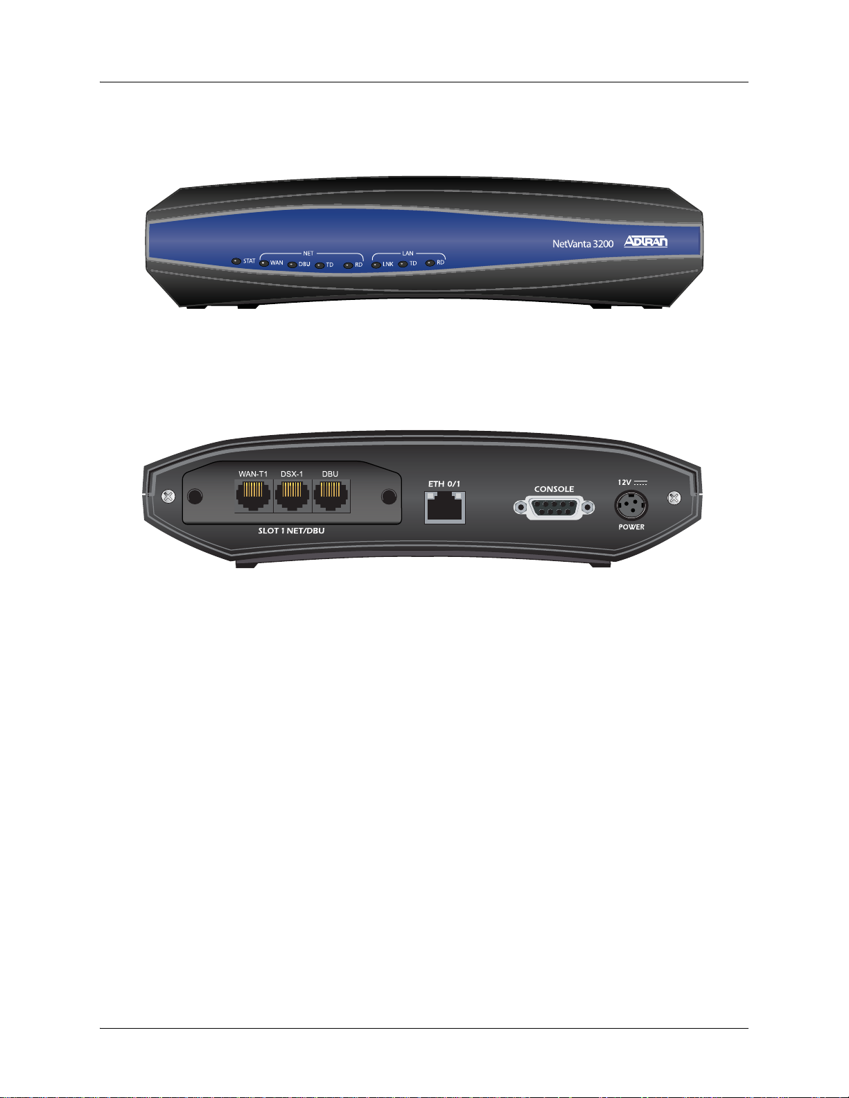
NetVanta 3200 Front Panel Design
The NetVanta 3200 front panel is shown below. Front panel LED descriptions are given in Table 1 on page 40.
Figure 1. NetVanta 3200 Front Panel Layout
NetVanta 3200 Rear Panel Design
The NetVanta 3200 rear panel is shown below. Appendix A on page 85 provides pinouts.
Figure 2. NetVanta 3200 Rear Panel Layout
NetVanta 3200 Rear Panel Interfaces and LEDs
SLOT 1 NET/DBU Option Slot
The SLOT 1 NET/DBU option slot supports various plug-in NIMs. These option modules are described
in the section Option Modules on page 41.
10/100Base-T Ethernet Interface and Activity LEDs
The Ethernet port (ETH 0/1) is an RJ-45 connector with LEDs. The amber activity LED flashes when
data traffic is being sent or received on the Ethernet port. The green link LED is on when the router has
a good connection to the LAN. The Ethernet port provides the following:
• 10Base-T or 100Base-T with a single connector
• Auto-negotiation
•CSMA/CD
• IEEE 802.3 compatibility
CONSOLE Interface
The CONSOLE interface is an EIA-232 serial port (DCE) that provides for local management and
configuration (via a DB-9 female connector)
18 Copyright © 2012 ADTRAN, Inc. 61200860L1-34AB
Page 19

NetVanta 3200/3300/3400 Series Physical Descriptions
Connection directly to an external modem requires a cross-over cable.
Power Connection
The rear panel has a 12V input for the power supply included in the shipment. Please refer to
Supplying Power to the Unit on page 69.
NetV anta 3205
The NetVanta 3205 (AC or DC powered) is a modular access router designed for cost-effective branch
office connectivity over MPLS, Frame Relay, multilink Frame Relay, PPP, MLPPP, or Ethernet networks.
For information on switch configuration for a specific application, refer to the configuration guides provided on
the ADTRAN Support Community
Command Reference Guide. All other related documents are also available online at
http://supportforums.adtran.com
NetVanta 3205 Features and Specifications
• Modular Network Interface: 56K/64K, T1/FT1, T1/FT1 NEBS, T1/FT1 + DSX-1, Dual T1, E1/FE1,
E1/FE1 + G.703, serial, SHDSL, or ADSL
• One integrated 10/100Base-T Ethernet port (RJ-45)
• Modular IP access routers for MPLS, Frame Relay, multilink Frame Relay, PPP, MLPPP, PPPoE,
ATM, and HDLC networks
• Integrated IP router with bridging
• Optional ISsec VPN supporting DES/3DES/AES encryption
• IP encapsulation over Frame Relay (RFC 1490)
• ADTRAN Operating System (AOS) command line interface (CLI)
• User-friendly, Web-based graphical user interface (GUI)
• Standards-based eBGP/iBGP, OSPF, RIP, static routing and bridging protocols
• Integral stateful inspection firewall protects against denial of service (DoS) attacks
• Quality of service (QoS) with low latency queuing (LLQ), weighted fair queuing (WFQ), class-based
weighted fair queuing (CBWFQ), and DiffServ marking
• Built-in alert and logging mechanisms
• Network address translation (NAT/NAPT), 1:1 NAT port translation, and NAT Traversal version 2
• NAT-compliant SIP ALG
• DHCP client, server, and relay
• XAUTH including RADIUS and RSA SecurID
• AAA support using local user database, RADIUS, and TACACS+
• Flash memory supports multiple images of AOS
• Remotely configurable and field upgradeable using TFTP or FTP
• Telnet, HTTP, SSH, or SNMP management options
• SNMP management
• n-Command network management
• Integrated EIA-232 DCE configuration port (DB-9)
. For details on the command line interface (CLI), refer to the AOS
.
61200860L1-34AB Copyright © 2012 ADTRAN, Inc. 19
Page 20

Physical Descriptions NetVanta 3200/3300/3400 Series
• Optional dial backup (ISDN BRI DIM, ISDN S/T DIM, or analog modem DIM)
• Front panel LEDs
• Size: 17.25-inch W x 1.26-inch H x 7.75-inch D
• AC Power Requirements: 6 W maximum, 60 mA (regardless of configuration)
• DC Power Requirements: 6 W maximum; +21 to +28.3 VDC (+24 VDC nominal); -40.5 to -64 VDC
(-48 VDC nominal)
• Operating Temperature: 0°C to 50°C
• RoHS compliant (Telecommunications exemption) (AC version only)
Network Interface Modules and Dial Backup Interface Modules Supported
The NetVanta 3205 supports a variety of interchangeable NIMs and DIMs. The NIMs available for the
NetVanta 3205 (AC or DC powered) provide a variety of WAN connectivity options including the
following:
•56K/64K (DDS)
• T1/FT1
• T1/FT1 + DSX-1
•Dual T1
• T1/FT1 NEBS (NetVanta 3205 DC only)
• E1/FE1
• E1/FE1 + G.703
• Serial (V.35/X.21/EIA 530)
• SHDSL, Annex A and Annex B
• ADSL, Annex A an d Annex B
If needed, an analog modem, ISDN BRI U, or ISDN BRI S/T DIM can plug onto the NIM, providing dial
backup capability. Refer to Installing Dial Backup and Network Interface Modules on page 74 for more
details.
NetVanta 3205 Shipping Contents
Each NetVanta 3205 unit is shipped in its own cardboard shipping carton. Open each carton carefully, and
avoid deep penetration into the carton with sharp objects.
After unpacking the unit, inspect it for possible shipping damage. If the equipment has been damaged in
transit, immediately file a claim with the carrier and contact ADTRAN Customer Service (refer to the
Support page on the ADTRAN website at http://www.adtran.com/support
).
Shipments of the NetVanta 3205 (AC) include the following items:
• NetVanta 3205 (AC) base unit with attached mounting ears/screws
• Quick start guide
• Detachable AC power cord
Shipments of the NetVanta 3205 (DC) include the following items:
• NetVanta 3205 (DC) base unit with attached mounting ears
• Quick start guide
20 Copyright © 2012 ADTRAN, Inc. 61200860L1-34AB
Page 21
NetVanta 3200/3300/3400 Series Physical Descriptions
WAN-T1 DSX-1 DBU
System bundles are shipped with a base unit, a network interface module, and other
appropriate contents based on the system-level solution ordered.
Option module shipping contents are given in Option Module Shipping Contents on
page 42.
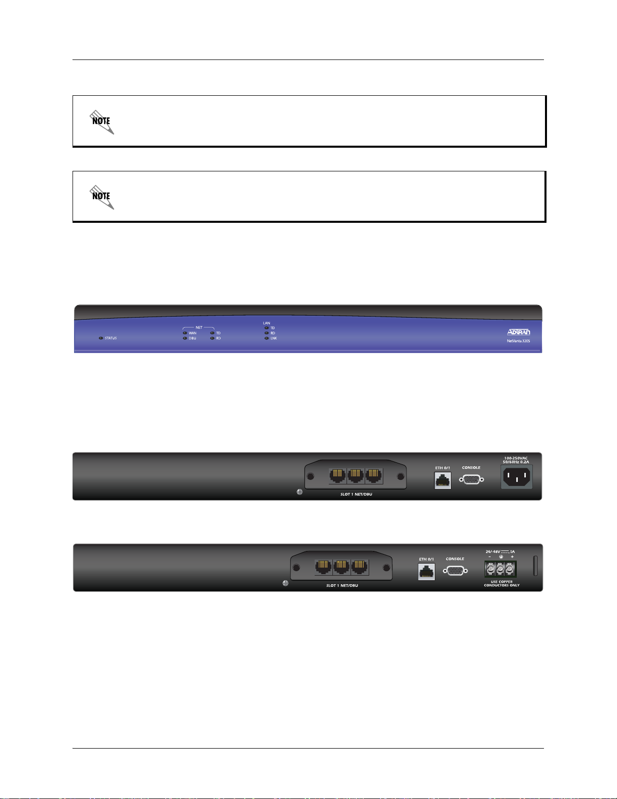
NetVanta 3205 Front Panel Design
The NetVanta 3205 front panel is shown below. Front panel LED descriptions are given in Table 1 on page
40.
Figure 3. NetVanta 3205 Front Panel Layout
NetVanta 3205 Rear Panel Design
The NetVanta 3205 AC and DC version rear panels are shown below with a module installed. Appendix A
on page 85 provides pinouts.
Figure 4. NetVanta 3205 (AC version) Rear Panel Layout
WAN-T1 DSX-1 DBU
Figure 5. NetVanta 3205 (DC version) Rear Panel Layout
NetVanta 3205 Rear Panel Interfaces and LEDs
SLOT 1 NET/DBU Option Slot
The SLOT 1 NET/DBU option slot supports various NIM plug-in option modules. These option
modules are described in the section Option Modules on page 41.
61200860L1-34AB Copyright © 2012 ADTRAN, Inc. 21
Page 22

Physical Descriptions NetVanta 3200/3300/3400 Series
10/100Base-T Ethernet Interface and Activity LEDs
The Ethernet port (ETH 0/1) is an RJ-45 connector with LEDs. The amber activity LED flashes when
data traffic is being sent or received on the Ethernet port. The green link LED is on when the router has
a good connection to the LAN. The Ethernet port provides the following:
• 10Base-T or 100Base-T with a single connector
• Auto-negotiation
•CSMA/CD
• IEEE 802.3 compatibility
CONSOLE Interface
The CONSOLE interface is an EIA-232 serial port (DCE) that provides for local management and
configuration (via a DB-9 female connector).
Connection directly to an external modem requires a cross-over cable.
Power Connection
The rear panel has a power input for connection to the power supply . Power supplies are shipped with
final destinations in mind. For example, domestic routers are shipped with a wallmount supply and
international routers are shipped with a universal input lump-in-line supply with the appropriate
cables. All of the 1U-high products have universal power supplies and are shipped with the appropriate
cable. Please refer to Supplying Power to the Unit on page 69 for connection details.
NetV anta 3305
The NetVanta 3305 is a modular access router designed for cost-effective branch office connectivity over
MPLS, Frame Relay, multilink Frame Relay, PPP, MLPPP, or Ethernet networks.
For VPN applications using the NetVanta 3305, the optional NetVanta VPN Accelerator Card provides
encryption/decryption and security acceleration services. Refer to Installing the NetVanta VPN Accelerator
Card (included in P/N 4200368L1) on page 77.
For information on switch configuration for a specific application, refer to the configuration guides provided on
the ADTRAN Support Community
Command Reference Guide. All other related documents are also available online at
http://supportforums.adtran.com
NetVanta 3305 Features and Specifications
• Modular Network Interface: 56K/64K, T1/FT1, T1/FT1 + DSX-1, Dual T1, E1/FE1, E1/FE1 + G.703,
serial, SHDSL, ADSL, or USB WWAN
• Optional VPN Accelerator Card provides encryption/decryption and security acceleration services
• Two integrated 10/100Base-T Ethernet ports (RJ-45)
• Modular IP access routers for MPLS, Frame Relay, multilink Frame Relay, PPP, MLPPP, PPPoE,
ATM, and HDLC networks
• Integrated IP router with bridging
• IP encapsulation over Frame Relay (RFC 1490)
• ADTRAN Operating System (AOS) command line interface (CLI)
. For details on the command line interface (CLI), refer to the AOS
.
22 Copyright © 2012 ADTRAN, Inc. 61200860L1-34AB
Page 23

NetVanta 3200/3300/3400 Series Physical Descriptions
• User-friendly, Web-based graphical user interface (GUI)
• Standards-based eBGP/iBGP, OSPF, RIP, static routing and bridging protocols
• Integral stateful inspection firewall protects against denial of service (DoS) attacks
• Quality of service (QoS) with low latency queuing (LLQ), weighted fair queuing (WFQ), class-based
weighted fair queuing (CBWFQ), and DiffServ marking
• Built-in alert and logging mechanisms
• Network address translation (NAT/NAPT), 1:1 NAT port translation, and NAT Traversal version 2
• NAT-compliant SIP ALG
• DHCP client, server, and relay
• XAUTH including RADIUS and RSA SecurID
• AAA support using local user database, RADIUS, and TACACS+
• Flash memory supports multiple images of AOS
• Remotely configurable and field upgradeable using TFTP or FTP
• Telnet, HTTP, SSH, or SNMP management options
• SNMP management
• n-Command network management
• Integrated EIA-232 DCE configuration port (DB-9)
• Optional dial backup (ISDN BRI DIM, ISDN S/T DIM, or analog modem DIM)
• Front panel LEDs
• Size: 17.25-inch W x 1.26-inch H x 7.75-inch D
• AC Power Requirements: 6 W maximum, 60 mA (regardless of configuration)
• Operating Temperature: 0°C to 50°C
• RoHS compliant (Telecommunications exemption)
Network Interface Modules and Dial Backup Interface Modules Supported
The NetVanta 3305 supports a variety of interchangeable NIMs and DIMs. The NIMs available for the
NetVanta 3305 provide a variety of WAN connectivity options including the following:
•56K/64K (DDS)
• T1/FT1
• T1/FT1 + DSX-1
•Dual T1
• E1/FE1
• E1/FE1 + G.703
• Serial (V.35/X.21/EIA 530)
• SHDSL, Annex A and Annex B
• ADSL, Annex A an d Annex B
•USB WWAN
If needed, an analog modem, ISDN BRI U, or ISDN BRI S/T DIM can plug onto the NIM, providing dial
backup capability. Refer to Installing Dial Backup and Network Interface Modules on page 74 for more
details.
Refer to Using a USB Cellular Modem with the NetVanta USB WWAN NIM on page 76 for details on
installing and removing a USB cellular modem from the USB WWAN NIM.
61200860L1-34AB Copyright © 2012 ADTRAN, Inc. 23
Page 24
Physical Descriptions NetVanta 3200/3300/3400 Series
NetVanta 3305 Shipping Contents
Each NetVanta 3305 unit is shipped in its own cardboard shipping carton. Open each carton carefully, and
avoid deep penetration into the carton with sharp objects.
After unpacking the unit, inspect it for possible shipping damage. If the equipment has been damaged in
transit, immediately file a claim with the carrier and contact ADTRAN Customer Service (refer to the
Support page on the ADTRAN website at http://www.adtran.com/support
).
Shipments of the NetVanta 3305 include the following items:
• NetVanta 3305 base unit with attached mounting ears/screws
• Quick start guide
• Detachable AC power cord
System bundles are shipped with a base unit, a network interface module, and other
appropriate contents based on the system-level solution ordered.
Option module shipping contents are given in Option Module Shipping Contents on
page 42.
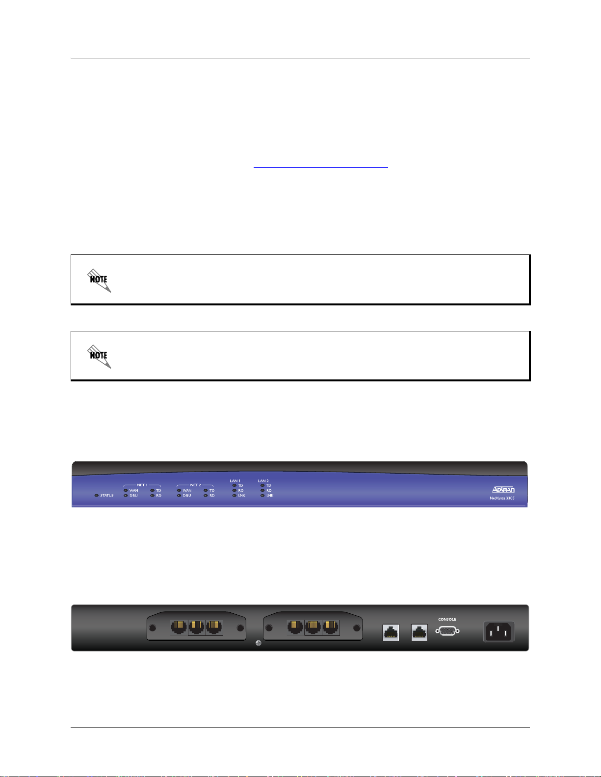
NetVanta 3305 Front Panel Design
The NetVanta 3305 front panel is shown below. Front panel LED descriptions are given in Table 1 on page
40.
Figure 6. NetVanta 3305 Front Panel Layout
NetVanta 3305 Rear Panel Design
The NetVanta 3305 rear panel is shown below with modules installed. Appendix A on page 85 provides
pinouts.
100-250VAC
WAN-T1 DSX-1 DBUWAN-T1 DSX-1 DBU
ETH 0/1 ETH 0/2
50/60Hz
SLOT 1 NET/DBU SLOT 2 NET/DBU
Figure 7. NetVanta 3305 Rear Panel Layout
24 Copyright © 2012 ADTRAN, Inc. 61200860L1-34AB
Page 25

NetVanta 3200/3300/3400 Series Physical Descriptions
NetVanta 3305 Rear Panel Interfaces and LEDs
NET/DBU Option Slots
The SLOT x NET/DBU option slots support various NIM plug-in option modules. These option
modules are described in the section Option Modules on page 41.
10/100Base-T Ethernet Interface and Activity LEDs
The Ethernet ports (ETH 0/1 and ETH 0/2) are RJ-45 connectors with LEDs. The amber activity LED
flashes when data traffic is being sent or received on the Ethernet port. The green link LED is on when
the router has a good connection to the LAN. The Ethernet port provides the following:
• 10Base-T or 100Base-T with a single connector
• Auto-negotiation
•CSMA/CD
• IEEE 802.3 compatibility
CONSOLE Interface
The CONSOLE interface is an EIA-232 serial port (DCE) that provides for local management and
configuration (via a DB-9 female connector).
Connection directly to an external modem requires a cross-over cable.
Power Connection
The rear panel has a power input for connection to the power supply . Power supplies are shipped with
final destinations in mind. For example, domestic routers are shipped with a wallmount supply and
international routers are shipped with a universal input lump-in-line supply with the appropriate
cables. All of the 1U-high products have universal power supplies and are shipped with the appropriate
cable. Please refer to Supplying Power to the Unit on page 69 for connection details.
NetV anta 3430
The NetVanta 3430 is a high-performance, modular IP access routers designed for cost-effective branch
office connectivity over MPLS, Frame Relay, multilink Frame Relay, PPP, MLPPP, or Ethernet networks.
For information on switch configuration for a specific application, refer to the configuration guides provided on
the ADTRAN Support Community
Command Reference Guide. All other related documents are also available online at
http://supportforums.adtran.com
NetVanta 3430 Features and Specifications
• Single-slot, dual-Ethernet modular IP router
• Modular Network Interface: 56K/64K DDS, T1/FT1, T1/FT1 + DSX-1, Dual T1, E1/FE1, E1/FE1 +
G.703, or ADSL (Annex A or Annex B), SHDSL (Annex A or Annex B), serial, or USB WWAN
• Modular IP access routers for MPLS, Frame Relay, multilink Frame Relay, PPP, MLPPP, PPPoE,
ATM, and HDLC networks
• High-performance processor
• Hardware en cry pti on en gine embedded
• On-board Flash memory
. For details on the command line interface (CLI), refer to the AOS
.
61200860L1-34AB Copyright © 2012 ADTRAN, Inc. 25
Page 26

Physical Descriptions NetVanta 3200/3300/3400 Series
• Expandable memory storage via a CompactFlash® card slot on the front panel and SODIMM slot
• Two integrated 10/100Base-T WAN/LAN ports
• ADTRAN Operating System (AOS) command line interface (CLI)
• User-friendly, Web-based graphical user interface (GUI)
• Standards-based BGP, OSPF, RIP, static routing, and bridging protocols
• Integral stateful inspection firewall protects against denial of service (DoS) attempts
• Flash memory supports multiple images of AOS
• Interchangeable network interface modules (NIMs)
• Dial backup to any PPP-compliant device
• Analog modem, ISDN BRI U, or ISDN BRI S/T dial backup interface modules (DIMs) available
• 500 ISsec VPN tunnels (software optional) with DES, 3DES, and AES encryption
• Compatible with ISsec VPN-equipped devices
• Quality of service (QoS) with class-based weighted fair queuing (CBWFQ), low latency queuing
(LLQ), weighted fair queuing (WFQ), and DiffServ marking
• Built-in alert and logging mechanisms
• Network address translation (NAT/NAPT) and NAT Traversal version 2
• NAT-compatible SIP ALG
• DHCP client, server, and relay
• XAUTH including RADIUS and RSA SecurID
• AAA support using local user database, RADIUS, and TACACS+
• TFTP, FTP, XMODEM for firmware upgrades and maintenance updates
• Telnet, HTTP, SSH, SSL, Syslog, craft/console port, or SNMP management options
• Field-upgradable and remotely configurable
• Supports up to two T1s of bandwidth
• 1U-high desktop or rackmountable metal enclosure (requires rackmount kit P/N 1200827E1, which
must be ordered separately, for rack mounting)
• Size: 1.7-inch H x 11.7-inch W x 7.5-inch D (1200820E1)
• Size: 1.7-inch H x 10.5-inch W x 5.8-inch D (1202820G1)
• AC Power Requirements: Auto-ranging power, 100 to 250 VAC, 50/60 Hz, 0.4 A maximum
• Operating Temperature: 0°C to 50°C
• RoHS compliant (Telecommunications exemption)
Network Interface Modules and Dial Backup Interface Modules Supported
The NetVanta 3430 supports a variety of interchangeable NIMs and DIMs. The NIMs available for the
NetVanta 3430 provide a variety of WAN connectivity options including the following:
•56K/64K (DDS)
• T1/FT1
• T1/FT1 + DSX-1
•Dual T1
• E1/FE1
• E1/FE1 + G.703
• Serial (V.35/X.21/EIA 530)
• SHDSL, Annex A and Annex B
26 Copyright © 2012 ADTRAN, Inc. 61200860L1-34AB
Page 27

NetVanta 3200/3300/3400 Series Physical Descriptions
• ADSL, Annex A an d Annex B
•USB WWAN
If needed, an analog modem, ISDN BRI U, or ISDN BRI S/T DIM can plug onto the NIM, providing dial
backup capability. Refer to Installing Dial Backup and Network Interface Modules on page 74 for more
details.
Refer to Using a USB Cellular Modem with the NetVanta USB WWAN NIM on page 76 for details on
installing and removing a USB cellular modem from the USB WWAN NIM.
NetVanta 3430 Shipping Contents Each NetVanta 3430 unit is shipped in its own cardboard shipping carton. Open each carton carefully, and
avoid deep penetration into the carton with sharp objects.
After unpacking the unit, inspect it for possible shipping damage. If the equipment has been damaged in
transit, immediately file a claim with the carrier and contact ADTRAN Customer Service (refer to the
Support page on the ADTRAN website at http://www.adtran.com/support
Domestic Shipping Contents
).
Shipments of the NetVanta 3430 domestic units include the following items:
• NetVan ta 34 30 base unit
• Quick start guide
• Rackmount brackets
• Wallmount bracket (P/N 1202820G1 only)
• 4 rubber mounting feet
• Po wer cord
International Shipping Contents
Shipments of the NetVanta 3430 international units include the following items:
• NetVan ta 34 30 base unit
• Quick start guide
• Rackmount brackets
• Wallmount bracket (P/N 1202820G1 only)
• 4 rubber mounting feet
• All necessary power cords
Option module shipping contents are given in Option Module Shipping Contents on
page 42.
The NetVanta 3430 ships with a 144-pin, 128 MB SODIMM (P/N 1200828G1)
installed. It can be upgraded to provide a maximum of 512 MB of memory using the
144-pin, 512 MB SODIMM (P/N 1200829G1).
61200860L1-34AB Copyright © 2012 ADTRAN, Inc. 27
Page 28

Physical Descriptions NetVanta 3200/3300/3400 Series
WAN-T1 DBU
CONSOLE
SLOT 1 NET / DBU
NetVanta 3430 Front Panel Design
The NetVanta 3430 front panel is shown below. Front panel LED descriptions are given in Table 1 on page 40.
In addition to the LEDs, this front panel contains a
CompactFlash slot for non volatile configuration storage and
compressed code storage. ADTRAN supports only ADTRAN-provided CompactFlash (16 MB to 1 GB) (refer
to the list of part numbers on the front cover). Refer to Installing a CompactFlash Card on page 80.
Figure 8. NetVanta 3430 (1202820G1) Front Panel Layout
NetVanta 3430 Rear Panel Design
The NetVanta 3430 rear panel is shown below with a module installed. Appendix A on page 85 provides
pinouts.
Figure 9. NetVanta 3430 (1202820G1) Rear Panel Layout
NetVanta 3430 Rear Panel Interfaces
SLOT 1 NET/DBU Option Slot
The SLOT 1 NET/DBU option slot supports various NIM plug-in option modules. These option
modules are described in the section Option Modules on page 41.
10/100Base-T Ethernet Interfaces
The Ethernet ports (ETH 0/1 and ETH 0/2) are RJ-45 connectors. These ports provide the following:
• 10Base-T or 100Base-T with a single connector
• Auto-negotiation
•CSMA/CD
• IEEE 802.3 compatibility
CONSOLE Interface
The CONSOLE interface is an EIA-232 serial port (DCE) that provides for local management and
configuration (via a DB-9 female connector).
Connection directly to an external modem requires a cross-over cable.
28 Copyright © 2012 ADTRAN, Inc. 61200860L1-34AB
Page 29

NetVanta 3200/3300/3400 Series Physical Descriptions
Power Connection
All of the 1U-high products have universal power supplies and are shipped with the appropriate cable.
Please refer to Supplying Power to the Unit on page 69 for connection details.
NetV anta 3448
The NetVanta 3448 is a high-performance modular access router designed for cost-effective branch office
connectivity over MPLS, Frame Relay, multilink Frame Relay, PPP, MLPPP, or Ethernet networks. It
offers an integrated 8-port fully managed Ethernet switch.
The NetVanta 3448 switch ports can be upgraded using the Octal Power over Ethernet (PoE) Upgrade
Bundle to provide PoE capability. PoE provides the ability to detect attached powered devices (PDs) and
deliver 48 VDC to the PDs via existing CAT 5 cabling. The NetVanta 3448 PoE option is fully compliant
with the IEEE 802.3af PoE standard.
For information on switch configuration for a specific application, refer to the configuration guides provided on
the ADTRAN Support Community
Command Reference Guide. All other related documents are also available online at
http://supportforums.adtran.com
NetVanta 3448 Features and Specifications
• Single-slot, dual-Ethernet modular IP router
• Modular Network Interface: 56K/64K DDS, T1/FT1, T1/FT1 + DSX-1, Dual T1, E1/FE1, E1/FE1 +
G.703, ADSL (Annex A or Annex B), SHDSL (Annex A or Annex B), serial, or USB WWAN
• High-performance processor
• Hardware en cry pti on en gine embedded
• On-board Flash memory (32 MB)
• Expandable memory storage via a CompactFlash card slot on the front panel and SODIMM slot
• Two integrated 10/100 Base-T WAN/LAN ports
• Integrated 8-port fully-managed Ethernet switch
• Optional Octal PoE upgrade for switch ports to provide (802.3af/Legacy) PoE capability
• ADTRAN Operating System (AOS) command line interface (CLI)
• User-friendly, Web-based graphical user interface (GUI)
• Modular IP access routers for MPLS, Frame Relay, multilink Frame Relay, PPP, MLPPP, PPPoE,
ATM, and HDLC networks
• Standards-based BGP, OSPF, RIP, static routing and bridging protocols
• Integral stateful inspection firewall protects against denial of service (DoS) attempts
• Flash memory supports multiple images of AOS
• Interchangeable network interface modules (NIMs)
• Dial backup to any PPP-compliant device
• Analog modem, ISDN BRI U, or ISDN BRI S/T dial backup interface modules (DIMs) available
• 500 ISsec VPN tunnels (optional) with DES, 3DES, and AES encryption
• Compatible with ISsec VPN-equipped devices
• Quality of service (QoS) with class-based weighted fair queuing (CBWFQ), low latency queuing
(LLQ), weighted fair queuing (WFQ), and DiffServ marking
• Built-in alert and logging mechanisms
• Network address translation (NAT/NAPT) and NAT Traversal version 2
. For details on the command line interface (CLI), refer to the AOS
.
61200860L1-34AB Copyright © 2012 ADTRAN, Inc. 29
Page 30

Physical Descriptions NetVanta 3200/3300/3400 Series
• NAT-compatible SIP ALG
• DHCP client, server, and relay
• XAUTH including RADIUS and RSA SecurID
• AAA support using local user database, RADIUS, and TACACS+
• TFTP, FTP, XMODEM for firmware upgrades and maintenance updates
• Telnet, HTTP, SSH, SSL, Syslog, craft/console port, or SNMP management options
• Field-upgradable and remotely configurable
• Supports up to two T1s of bandwidth
• 1U-high desktop or rackmountable metal enclosure (requires rackmount kit P/N 1200827E1, which
must be ordered separately, for rack mounting)
• Size: 1.7-inch H x 11.7-inch W x 7.5-inch D
• AC Power Requirements: Auto-ranging power, 100 to 250 VAC, 50/60 Hz, 0.4 A maximum
• Operating Temperature: 0°C to 50°C
• RoHS compliant (Telecommunications exemption)
Network Interface Modules and Dial Backup Interface Modules Supported
The NetVanta 3448 supports a variety of interchangeable NIMs and DIMs. The NIMs available for the
NetVanta 3448 provide a variety of WAN connectivity options including the following:
•56K/64K (DDS)
• T1/FT1
• T1/FT1 + DSX-1
•Dual T1
• E1/FE1
• E1/FE1 + G.703
• Serial (V.35/X.21/EIA 530)
• SHDSL, Annex A or Annex B
• ADSL, Annex A or Annex B
•USB WWAN
If needed, an analog modem, ISDN BRI U, or ISDN BRI S/T DIM can plug onto the NIM, providing dial
backup capability. Refer to Installing Dial Backup and Network Interface Modules on page 74 for more
details.
Refer to Using a USB Cellular Modem with the NetVanta USB WWAN NIM on page 76 for details on
installing and removing a USB cellular modem from the USB WWAN NIM.
NetVanta 3448 Shipping Contents
Each NetVanta 3448 unit is shipped in its own cardboard shipping carton. Open each carton carefully, and
avoid deep penetration into the carton with sharp objects.
After unpacking the unit, inspect it for possible shipping damage. If the equipment has been damaged in
transit, immediately file a claim with the carrier and contact ADTRAN Customer Service (refer to the
Support page on the ADTRAN website at http://www.adtran.com/support
30 Copyright © 2012 ADTRAN, Inc. 61200860L1-34AB
).
Page 31

NetVanta 3200/3300/3400 Series Physical Descriptions
Domestic Shipping Contents
Shipments of the NetVanta 3448 domestic units include the following items:
• NetVan ta 34 48 base unit
• Quick start guide
• 4 rubber mounting feet
• Po wer cord
• PoE external power supply with power cord (with PoE option only)
International Shipping Contents
Shipments of the NetVanta 3448 international units include the following items:
• NetVan ta 34 48 base unit
• Quick start guide
• 4 rubber mounting feet
• All necessary power cords
• PoE external power supply with all necessary power cords (with PoE option only)
Option module shipping contents are given in Option Module Shipping Contents on
page 42.
The NetVanta 3448 ships with a 200-pin, 128 MB SODIMM (P/N 1200812E1)
installed. It can be upgraded to pr ovid e 256 MB of memory using the 200- pin, 256 MB
SODIMM (P/N 1200813E1) or 512 MB using the 200-pin, 512 MB SODIMM (P/N
1200814E1).
NetVanta 3448 Front Panel Design
The NetVanta 3448 front panel is shown below. Front panel LED descriptions are given in Table 1 on page
40. In addition to the LEDs, this front panel contains a
CompactFlash slot for nonvolatile configuration
storage and compressed code storage. ADTRAN supports only ADTRAN-provided CompactFlash (16 MB
to 1 GB) (refer to the list of part numbers on the front cover). Refer to Installing a CompactFlash Card on
page 80.
Figure 10. NetVanta 3448 Front Panel Layout
61200860L1-34AB Copyright © 2012 ADTRAN, Inc. 31
Page 32

Physical Descriptions NetVanta 3200/3300/3400 Series
WAN-T1 DBU
CONSO LE
SLOT 1 NET / DBU
48 V
NetVanta 3448 Rear Panel Design
The NetVanta 3448 rear panel is shown below with a module installed. Appendix A on page 85 provides
pinouts.
Figure 11. NetVanta 3448 Rear Panel Layout
NetVanta 3448 Rear Panel Interfaces
SLOT 1 NET/DBU Option Slot
The SLOT 1 NET/DBU option slot supports various NIM plug-in option modules. These option
modules are described in the section Option Modules on page 41.
PoE
The NetVanta 3448 has a 48 VDC port on the rear panel to provide the voltage required for PoE
applications. This port is active only if the NetVanta 3448 has been ordered with the PoE option. Note
that the NetVanta 3448 itself cannot be powered by this port.
8 Switch Port Interfaces
Ports 1 through 8 are RJ-45 connectors used to access the fully managed 10/100Base-T Ethernet
switch.
10/100Base-T Ethernet Interfaces
The Ethernet ports (ETH 0/1 and ETH 0/2) are RJ-45 connectors.
CONSOLE Interface
The CONSOLE interface is an EIA-232 serial port (DCE) that provides for local management and
configuration (via a DB-9 female connector).
Connection directly to an external modem requires a cross-over cable.
Power Connection
All of the 1U-high products have universal power supplies and are shipped with the appropriate cable.
Please refer to Supplying Power to the Unit on page 69 for connection details.
NetV anta 3450
The NetVanta 3450 is a high-performance, modular IP access router designed for cost-effective branch
office connectivity over MPLS, Frame Relay, multilink Frame Relay, PPP, MLPPP, or Ethernet networks.
32 Copyright © 2012 ADTRAN, Inc. 61200860L1-34AB
Page 33

NetVanta 3200/3300/3400 Series Physical Descriptions
For information on switch configuration for a specific application, refer to the configuration guides provided on
the ADTRAN Support Community
. For details on the command line interface (CLI), refer to the AOS
Command Reference Guide. All other related documents are also available online at
http://supportforums.adtran.com
.
NetVanta 3450 Features and Specifications
• Dual-slot, dual-Ethernet modular IP router
• Modular Network Interface: 56K/64K DDS, T1/FT1, T1/FT1 + DSX-1, Dual T1, E1/FE1, E1/FE1 +
G.703, or ADSL (Annex A or Annex B), SHDSL (Annex A or Annex B), serial, or USB WWAN
• Modular IP access routers for MPLS, Frame Relay, multilink Frame Relay, PPP, MLPPP, PPPoE,
ATM, and HDLC networks
• High-performance processor
• Hardware en cry pti on en gine embedded
• On-board Flash memory
• Expandable memory storage via a CompactFlash card slot on the front panel
• Two integrated 10/100Base-T WAN/LAN ports
• ADTRAN Operating System (AOS) command line interface (CLI)
• User-friendly, Web-based graphical user interface (GUI)
• Standards-based BGP, OSPF, RIP, static routing, and bridging protocols
• Integral stateful inspection firewall protects against denial of service (DoS) attempts
• Flash memory supports multiple images of AOS
• Interchangeable network interface modules (NIMs)
• Dial backup to any PPP-compliant device
• Analog modem, ISDN BRI U, or ISDN BRI S/T dial backup interface modules (DIMs) available
• 500 ISsec VPN tunnels (software optional) with DES, 3DES, and AES encryption
• Compatible with ISsec VPN-equipped devices
• Quality of service (QoS) with class-based weighted fair queuing (CBWFQ), low latency queuing
(LLQ), weighted fair queuing (WFQ), and DiffServ marking
• Built-in alert and logging mechanisms
• Network address translation (NAT/NAPT) and NAT Traversal version 2
• NAT-compatible SIP ALG
• DHCP client, server, and relay
• XAUTH including RADIUS and RSA SecurID
• AAA support using local user database, RADIUS, and TACACS+
• TFTP, FTP, XMODEM for firmware upgrades and maintenance updates
• Telnet, HTTP, SSH, SSL, Syslog, craft/console port, or SNMP management options
• Field-upgradable and remotely configurable
• Supports up to two T1s of bandwidth
• 1U-high desktop or rackmountable metal enclosure (requires rackmount kit P/N 1200827E1, which
must be ordered separately, for rack mounting)
• Size: 1.7-inch H x 17.2-inch W x 8.0-inch D
• AC Power Requirements: Auto-ranging power, 100 to 250 VAC, 50/60 Hz, 0.4 A maximum
• Operating Temperature: 0°C to 50°C
• RoHS compliant (Telecommunications exemption)
61200860L1-34AB Copyright © 2012 ADTRAN, Inc. 33
Page 34

Physical Descriptions NetVanta 3200/3300/3400 Series
Network Interface Modules and Dial Backup Interface Modules Supported
The NetVanta 3450 supports a variety of interchangeable NIMs and DIMs. The NIMs available for the
NetVanta 3450 provide a variety of WAN connectivity options including the following:
•56K/64K (DDS)
• T1/FT1
• T1/FT1 + DSX-1
•Dual T1
• E1/FE1
• E1/FE1 + G.703
• Serial (V.35/X.21/EIA 530)
• SHDSL, Annex A and Annex B
• ADSL, Annex A an d Annex B
•USB WWAN
If needed, an analog modem, ISDN BRI U, or ISDN BRI S/T DIM can plug onto the NIM, providing dial
backup capability. Refer to Installing Dial Backup and Network Interface Modules on page 74 for more
details.
Refer to Using a USB Cellular Modem with the NetVanta USB WWAN NIM on page 76 for details on
installing and removing a USB cellular modem from the USB WWAN NIM.
NetVanta 3450 Shipping Contents Each NetVanta 3450 unit is shipped in its own cardboard shipping carton. Open each carton carefully, and
avoid deep penetration into the carton with sharp objects.
After unpacking the unit, inspect it for possible shipping damage. If the equipment has been damaged in
transit, immediately file a claim with the carrier and contact ADTRAN Customer Service (refer to the
Support page on the ADTRAN website at http://www.adtran.com/support
Domestic Shipping Contents
).
Shipments of the NetVanta 3450 domestic units include the following items:
• NetVan ta 34 50 base uni t with attached mounting brackets and screws
• Quick start guide
• Po wer cord
International Shipping Contents
Shipments of the NetVanta 3450 international units include the following items:
• NetVan ta 34 50 base uni t with attached mounting brackets and screws
• Quick start guide
• All necessary power cords
Option module shipping contents are given in Option Module Shipping Contents on
page 42.
34 Copyright © 2012 ADTRAN, Inc. 61200860L1-34AB
Page 35

NetVanta 3200/3300/3400 Series Physical Descriptions
Status
WAN 2
DBU 2
ETH1
ETH2
CompactFlash
NetVanta 3450
WAN 1
DBU 1
CONSOLE
SLOT 2 NET/DBU
SLOT 1 NET/DBU
ETH 0/2
ETH 0/1
NetVanta 3450 Front Panel Design
The NetVanta 3450 front panel is shown below. Front panel LED descriptions are given in Table 1 on page 40.
Figure 12. NetVanta 3450 Front Panel Layout
CONSOLE Interface
The CONSOLE interface is an EIA-232 serial port (DCE) that provides for local management and
configuration (via a DB-9 female connector).
Connection directly to an external modem requires a cross-over cable.
CompactFlash
The front panel contains a
CompactFlash slot for nonvolatile configuration storage and compressed code
storage. ADTRAN supports only ADTRA N - p r o v i d e d C o m p a c t F lash (16 MB to 1 GB) (refer to the list of
part numbers on the front cover). Refer to Installing a CompactFlash Card on page 80.
NetVanta 3450 Rear Panel Design
The NetVanta 3450 rear panel is shown below with a module installed. Appendix A on page 85 provides
pinouts.
Figure 13. NetVanta 3450 Rear Panel Layout
NetVanta 3450 Rear Panel Interfaces
SLOT 1/SLOT 2 NET/DBU Option Slots
The SLOT 1/SLOT 2 NET/DBU option slots support various NIM plug-in option modules. These
option modules are described in the section Option Modules on page 41.
10/100Base-T Ethernet Interfaces
The Ethernet ports (ETH 0/1 and ETH 0/2) are RJ-45 connectors. These ports provide the following:
• 10Base-T or 100Base-T dual stacked connector
• Auto-MDIX
• Auto-negotiation
•CSMA/CD
• IEEE 802.3 compatibility
61200860L1-34AB Copyright © 2012 ADTRAN, Inc. 35
Page 36

Physical Descriptions NetVanta 3200/3300/3400 Series
Power Connection
All of the 1U-high products have universal power supplies and are shipped with the appropriate cable.
Please refer to Supplying Power to the Unit on page 69 for connection details.
NetV anta 3458
The NetVanta 3458 is a high-performance, modular IP access router designed for cost-effective branch
office connectivity over MPLS, Frame Relay, multilink Frame Relay, PPP, MLPPP, or Ethernet networks.
It offers an integrated 8-port fully managed Ethernet switch.
The NetVanta 3458 switch ports can be upgraded using the Octal Power over Ethernet (PoE) Upgrade
Bundle to provide PoE capability. PoE provides the ability to detect attached powered devices (PDs) and
deliver 48 VDC to the PDs via existing CAT 5 cabling. The NetVanta 3458 PoE option is fully compliant
with the IEEE 802.3af PoE standard.
For information on switch configuration for a specific application, refer to the configuration guides provided on
the ADTRAN Support Community
Command Reference Guide. All other related documents are also available online at
http://supportforums.adtran.com
NetVanta 3458 Features and Specifications
• Dual-slot, dual-Ethernet modular IP router
• Modular Network Interface: 56K/64K DDS, T1/FT1, T1/FT1 + DSX-1, Dual T1, E1/FE1, E1/FE1 +
G.703, or ADSL (Annex A or Annex B), SHDSL (Annex A or Annex B), serial, or USB WWAN
• Modular IP access router for MPLS, Frame Relay, multilink Frame Relay, PPP, MLPPP, PPPoE, ATM,
and HDLC networks
• Embedded eight port 10/100Base-T Ethernet switch
• Switch ports can optionally be equipped to provide (802.3af) PoE
• High-performance processor
• Hardware en cry pti on en gine embedded
• On-board Flash memory
• Expandable memory storage via a CompactFlash card slot on the front panel
• Two integrated 10/100Base-T WAN/LAN ports
• ADTRAN Operating System (AOS) command line interface (CLI)
• User-friendly, Web-based graphical user interface (GUI)
• Standards-based BGP, OSPF, RIP, static routing, and bridging protocols
• Integral stateful inspection firewall protects against denial of service (DoS) attempts
• Flash memory supports multiple images of AOS
• Interchangeable network interface modules (NIMs)
• Dial backup to any PPP-compliant device
• Analog modem, ISDN BRI U, or ISDN BRI S/T dial backup interface modules (DIMs) available
• 500 ISsec VPN tunnels (software optional) with DES, 3DES, and AES encryption
• Compatible with ISsec VPN-equipped devices
• Quality of service (QoS) with class-based weighted fair queuing (CBWFQ), low latency queuing
(LLQ), weighted fair queuing (WFQ), and DiffServ marking
• Built-in alert and logging mechanisms
• Network address translation (NAT/NAPT) and NAT Traversal version 2
. For details on the command line interface (CLI), refer to the AOS
.
36 Copyright © 2012 ADTRAN, Inc. 61200860L1-34AB
Page 37

NetVanta 3200/3300/3400 Series Physical Descriptions
• NAT-compatible SIP ALG
• DHCP client, server, and relay
• XAUTH including RADIUS and RSA SecurID
• AAA support using local user database, RADIUS, and TACACS+
• TFTP, FTP, XMODEM for firmware upgrades and maintenance updates
• Telnet, HTTP, SSH, SSL, Syslog, craft/console port, or SNMP management options
• Field-upgradable and remotely configurable
• Supports up to two T1s of bandwidth
• 1U-high desktop or rackmountable metal enclosure (requires rackmount kit P/N 1200827E1, which
must be ordered separately, for rack mounting)
• Size: 1.7-inch H x 17.2-inch W x 8.0-inch D
• AC Power Requirements: Auto-ranging power, 100 to 250 VAC, 50/60 Hz, 0.4 A maximum
• Operating Temperature: 0°C to 50°C
• RoHS compliant (Telecommunications exemption)
Network Interface Modules and Dial Backup Interface Modules Supported
The NetVanta 3458 supports a variety of interchangeable NIMs and DIMs. The NIMs available for the
NetVanta 3458 provide a variety of WAN connectivity options including the following:
•56K/64K (DDS)
• T1/FT1
• T1/FT1 + DSX-1
•Dual T1
• E1/FE1
• E1/FE1 + G.703
• Serial (V.35/X.21/EIA 530)
• SHDSL, Annex A and Annex B
• ADSL, Annex A an d Annex B
•USB WWAN
If needed, an analog modem, ISDN BRI U, or ISDN BRI S/T DIM can plug onto the NIM, providing dial
backup capability. Refer to Installing Dial Backup and Network Interface Modules on page 74 for more
details.
Refer to Using a USB Cellular Modem with the NetVanta USB WWAN NIM on page 76 for details on
installing and removing a USB cellular modem from the USB WWAN NIM.
NetVanta 3458 Shipping Contents
Each NetVanta 3458 unit is shipped in its own cardboard shipping carton. Open each carton carefully, and
avoid deep penetration into the carton with sharp objects.
After unpacking the unit, inspect it for possible shipping damage. If the equipment has been damaged in
transit, immediately file a claim with the carrier and contact ADTRAN Customer Service (refer to the
Support page on the ADTRAN website at http://www.adtran.com/support
61200860L1-34AB Copyright © 2012 ADTRAN, Inc. 37
).
Page 38

Physical Descriptions NetVanta 3200/3300/3400 Series
PoE
Status
WAN 2
DBU 2
ETH1
ETH2
SWITCH
CompactFlash
NetVanta 3458
WAN 1
DBU 1
CONSOLE
1
5
2
6
3
7
4
8
Domestic Shipping Contents
Shipments of the NetVanta 3458 domestic units include the following items:
• NetVan ta 34 58 base uni t with attached mounting brackets and screws
• Quick start guide
• Po wer cord
International Shipping Contents
Shipments of the NetVanta 3458 international units include the following items:
• NetVan ta 34 58 base uni t with attached mounting brackets and screws
• Quick start guide
• All necessary power cords
Option module shipping contents are given in Option Module Shipping Contents on
page 42.
NetVanta 3458 Front Panel Design
The NetVanta 3458 front panel is shown below. Front panel LED descriptions are given in Table 1 on page 40.
Figure 14. NetVanta 3458 Front Panel Layout
CONSOLE Interface
The CONSOLE interface is an EIA-232 serial port (DCE) that provides for local management and
configuration (via a DB-9 female connector).
Connection directly to an external modem requires a cross-over cable.
CompactFlash
The front panel contains a
CompactFlash slot for nonvolatile configuration storage and compressed code
storage. ADTRAN supports only ADTRA N - p r o v i d e d C o m p a c t F lash (16 MB to 1 GB) (refer to the list of
part numbers on the front cover). Refer to Installing a CompactFlash Card on page 80.
38 Copyright © 2012 ADTRAN, Inc. 61200860L1-34AB
Page 39

NetVanta 3200/3300/3400 Series Physical Descriptions
NetVanta 3458 Rear Panel Design
The NetVanta 3458 rear panel is shown below with a module installed. Appendix A on page 85 provides
pinouts.
SLOT 1 NET/DBU
SLOT 2 NET/DBU
SWITCH
2
1
PoE
48V
5
6
ETH 0/1
3
4
7
8
ETH 0/2
Figure 15. NetVanta 3458 Rear Panel Layout
NetVanta 3458 Rear Panel Interfaces
SLOT 1/SLOT 2 NET/DBU Option Slots
The SLOT 1/SLOT 2 NET/DBU option slots support various NIM plug-in option modules. These
option modules are described in the section Option Modules on page 41.
PoE
The NetVanta 3458 has a 48 VDC port on the rear panel to provide the voltage required for PoE
applications. This port is active only if the NetVanta 3458 has been ordered with the PoE option. Note
that the NetVanta 3458 itself cannot be powered by this port.
8 Switch Port Interfaces
Ports 1 through 8 are RJ-45 connectors used to access the fully managed 10/100Base-T Ethernet
switch.
10/100Base-T Ethernet Interfaces
The Ethernet ports (ETH 0/1 and ETH 0/2) are RJ-45 connectors. These ports provide the following:
• 10Base-T or 100Base-T dual stacked connector
• Auto-MDIX
• Auto-negotiation
•CSMA/CD
• IEEE 802.3 compatibility
Power Connection
All of the 1U-high products have universal power supplies and are shipped with the appropriate cable.
Please refer to Supplying Power to the Unit on page 69 for connection details.
61200860L1-34AB Copyright © 2012 ADTRAN, Inc. 39
Page 40

Physical Descriptions NetVanta 3200/3300/3400 Series
NetV anta 3000 Series Front Panel LEDs
Table 1 describes the front panel LEDs.
Table 1. NetVanta 3000 Series Front Panel LEDs
LED Color Indication
STATUS (STAT) Green (flashing) The unit is powering up. On power up the STAT LED flashes rapidly
for five seconds, during which time the user can escape to boot mode
from the console port.
Green (solid) The power is on and self-test passed.
Red (solid) The power is on, but the self-test failed or the boot mode (if
applicable) code could not be booted.
WAN Off No NIM is installed, or interface is administratively down.
Green (solid) The link is up and everything is operational.
Green (flashing) The port has activity (3430/3448 only).
Red (solid) An alarm condition is occurring on the WAN interface, or there is a
self-test failure.
Amber (solid) The unit is in test.
DBU Off No DIM is installed.
Green (solid) The DIM is ready. For the ISDN BRI DIM, green solid indicates that
the negotiation with the switch is complete.
Green (flashing) The unit is in dial backup.
Red (solid) An alarm condition is occurring on the DBU interface, or there is a
self-test failure.
Amber (solid) The unit is in test.
NET TD/RD (not
present on all units)
LAN TD/RD (not
present on all units)
LNK (not present
on all units)
POE (not present
on all units)
ETH1/ETH2 (not
present on all units)
INET
(not present on all
units)
SWITCH
(not present on all
units)
VPN
(not present on all
units)
Off There is no activity on the WAN or DBU port.
Green (flashing) There is activity on the WAN or DBU port.
Off There is no activity on the Ethernet port.
Green (flashing) There is activity on the Ethernet port.
Green (solid) The 10Base-T Ethernet link is up.
Amber (solid) The 100Base-T Ethernet link is up.
Off PoE card not installed, or no attached devices are being powered.
Green (solid) PoE card is actively powering an attached device.
Red (solid) PoE card has detected a fault condition on an attached device.
Off The port is administratively disabled or does not have link.
Green (solid) The port is enabled and the link is up.
Amber (flashing) The port has activity (transmit or receive).
Off PPP or PPPoE is not connected, IP has no IP address via DHCP, or
IP is static.
Green (solid) PPP or PPPoE is connected or IP has an address via DHCP.
Green (flashing) WAN interface is attempting to obtain an IP address via DHCP.
Off The port is administratively disabled or does not have link.
Green (solid) The port is enabled and the link is up.
Amber (flashing) The port has activity (transmit or receive).
Off No encrypted traffic.
On Encrypted traffic present.
40 Copyright © 2012 ADTRAN, Inc. 61200860L1-34AB
Page 41

NetVanta 3200/3300/3400 Series Option Modules
3. OPTION MODULES
The NetVanta 3000 Series accepts several option modules designed to meet a variety of networking
requirements. The option modules are of two types: plug-in network interface modules (NIMs) and plugon dial backup interface modules (DIMs).
NIMs are cards that plug directly into the option module slots (labeled
SLOT
2 NET/DBU), located on the rear of the base unit. These cards provide the following types of
SLOT 1 NET/DBU or
interfaces:
• NetVanta 56K/64K NIM (P/N 1200861L1) on page 45
• NetVanta T1/FT1 NIM (P/N 1202862L1) on page 46
• NetVanta T1/FT1 NEBS NIM (P/N 1200862L2#NEBS) on page 47
• NetVanta T1/FT1 + DSX-1 NIM (P/N 1202863L1) on page 48
• NetVanta Dual T1 NIM (P/N 1200872L1/1202872L1) on page 49
• NetVanta E1/FE1 NIM (P/N 1200868E1/L1) on page 50
• NetVanta E1/FE1 + G.703 NIM (P/N 1200878E1/L1) on page 51
• NetVanta Serial NIM (P/N 1200866E1) on page 52
• NetVanta SHDSL NIM, Annex A (P/N 1200936E1) on page 5 3
• NetVanta SHDSL NIM, Annex B (P/N 1200937E1) on page 5 4
• NetVanta ADSL NIM, Annex A (P/N 1202869E1) on page 55
• NetVanta ADSL NIM, Annex B (P/N 1202889E1) on page 56
• NetVanta USB WWAN NIM (P/N 1702803F1) on page 57
DIMs are plug-on cards that plug directly onto the NIM prior to installation into the base unit. A DIM must
be plugged onto a NIM in order for the
DBU port on the NIM to be active. The NetVanta 3000 Series
supports three DIMs (only one DIM per slot can be installed):
• NetVanta Analog Modem DIM (P/N 1200864L1) on page 58
• NetVanta ISDN BRI DIM (P/N 1200865L1) on page 59
• NetVanta ISDN S/T DIM (P/N 1200875L1) on page 60
This section describes each module, providing individual card shipping contents, specifications, and
features. Refer to Connector Pin Definitions on page 85 for pinout information. Installing Dial Backup
and Network Interface Modules on page 74 provides information on installing the modules.
Refer to Using a USB Cellular Modem with the NetVanta USB WWAN NIM on page 76 for details on
installing and removing a USB cellular modem from the USB WWAN NIM.
61200860L1-34AB Copyright © 2012 ADTRAN, Inc. 41
Page 42

Option Modules NetVanta 3200/3300/3400 Series
Option Module Shipping Contents
NetVanta 56K/64K NIM (1200861L1)
Shipments of the 56K/64K NIM include the following items:
• 56K/64K Network Interface Module
• Quick start guide
• 6-foot RJ-45 to RJ-45 cable (ADTRAN P/N 3127004)
NetVanta T1/FT1 NIM (1202862L1)
Shipments of the T1/FT1 NIM include the following items:
• T1/FT1 Network Interface Module
• Quick start guide
• 15-foot RJ-45 to RJ-45 cable (ADTRAN P/N 3125M008@A)
NetVanta T1/FT1 NEBS NIM (1200862L2#NEBS)
Shipments of the T1/FT1 NEBS NIM include the following items:
• T1/FT1 NEBS Network Interface Module
• Quick start guide
• 15-foot RJ-45 to RJ-45 cable (ADTRAN P/N 3125M008@A)
NetVanta T1/FT1 + DSX-1 NIM (1202863L1)
Shipments of the T1/FT1 + DSX-1 NIM include the following items:
• T1/FT1 + DSX-1 Network Interface Module
• Quick start guide
• 15-foot RJ-45 to RJ-45 cable (ADTRAN P/N 3125M008@A)
NetVanta Dual T1 NIM (1200872L1/1202872L1)
Shipments of the Dual T1 NIM include the following items:
• Dual T1 Network Interface Module
• Quick start guide
• Two 15-foot RJ-45 to RJ-45 cable (ADTRAN P/N 3125M008@A)
NetVanta E1/FE1 NIM (1200868E1/L1)
Shipments of the E1/FE1 NIM include the following items:
• E1/FE1 Network Interface Module
• Quick start guide
• 15-foot RJ-45 to RJ-45 cable (ADTRAN P/N 3125M008@A)
NetVanta E1/FE1 + G.703 NIM (1200878E1/L1)
Shipments of the E1/FE1 + G.703 NIM include the following items:
• E1/FE1 + G.703 Network Interface Module
• Quick start guide
• 15-foot RJ-45 to RJ-45 cable (ADTRAN P/N 3125M008@A)
42 Copyright © 2012 ADTRAN, Inc. 61200860L1-34AB
Page 43

NetVanta 3200/3300/3400 Series Option Modules
NetVanta Serial NIM (1200866E1)
Shipments of the Serial NIM include the following items:
• Serial Network Interface Module
• Quick start guide
• 15-foot RJ-45 to RJ-45 cable (ADTRAN P/N 3125M008@A)
NetVanta SHDSL NIM, Annex A (1200936E1)
Shipments of the SHDSL NIM, Annex A, include the following items:
• SHDSL Network Interface Module
• Quick start guide
• 15-foot RJ-45 to RJ-45 cable (ADTRAN P/N 3125M008@A)
NetVanta SHDSL NIM, Annex B (1200937E1)
Shipments of the SHDSL NIM, Annex B, include the following items:
• SHDSL Network Interface Module
• Quick start guide
• 15-foot RJ-45 to RJ-45 cable (ADTRAN P/N 3125M008@A)
NetVanta ADSL NIM, Annex A (1202869E1)
Shipments of the ADSL NIM, Annex A, include the following items:
• ADSL Network Interface Module
• Quick start guide
• 7-foot RJ-11 to RJ-11 cable (ADTRAN P/N 3127014)
NetVanta ADSL NIM, Annex B (1202889E1)
Shipments of the ADSL NIM, Annex B, include the following items:
• ADSL Network Interface Module
• Quick start guide
• 7-foot RJ-11 to RJ-11 cable (ADTRAN P/N 3127014)
NetVanta USB WWAN NIM (1702803F1)
Shipments of the USB WWAN, include the following items:
• USB WWAN Network Interface Module
• Quick start guide
NetVanta Analog Modem DIM (1200864L1)
Shipments of the Analog Modem DIM include the following items:
• Analog Modem Dial Backup Interface Module
• Quick start guide
• 7-foot RJ-45 to RJ-11 cable (ADTRAN P/N 3125M007@A)
NetVanta ISDN BRI DIM (1200865L1)
Shipments of the ISDN BRI DIM include the following items:
• ISDN BRI Dial Backup Interface Module
• Quick start guide
• 7-foot RJ-45 to RJ-11 cable (ADTRAN P/N 3125M007@A)
61200860L1-34AB Copyright © 2012 ADTRAN, Inc. 43
Page 44

Option Modules NetVanta 3200/3300/3400 Series
NetVanta ISDN S/T DIM (1200875L1)
Shipments of the ISDN S/T DIM include the following items:
• ISDN S/T Dial Backup Interface Module
• Quick start guide
• 7-foot RJ-45 to RJ-11 cable (ADTRAN P/N 3125M007@A)
Option modules are intended to be serviced by qualified service personnel only.
System bundles are shipped with a base unit, a network interface module, and other
appropriate contents based on the system-level solution ordered.
44 Copyright © 2012 ADTRAN, Inc. 61200860L1-34AB
Page 45

NetVanta 3200/3300/3400 Series Option Modules
Features and Specifications
Operating Modes
• Dedicated DDS (leased line)
DDS Interface
• Supported Standards: AT&T TR 62310
• 4-wire, full-duplex
• Receiver Sensitivity: -45 dB, all rates
• Data Rates: 56K, 64K, and auto
• Connector: RJ-4 8C
Clock Source
•Network
•Internal
Diagnostics
• CSU and DSU Loopbacks
Compliance
• EMC - see Electromagnetic Compatibility
(EMC) Table on page 6.
• ACTA/FCC Part 68
• IC CS-03
• UL/CUL 60950-1
Environmental
• Operating Temperature: 0°C to 50°C
• Storage Temperature: -20°C to 70°C
• Relative Humidity: Up to 95 percent,
noncondensing
Physical
• Dimensions: 2.75-inch W x 4.25-inch D
Network Interface Modules
NetVanta 56K/64K NIM (P/N 1200861L1)
The NetVanta 56K/64K NIM (shown in Figure 16) provides a DDS WAN interface for the NetVanta 3000
Series. This module provides a single 56K or 64K DDS network interface. See Table A-6 on page 87 for
the WAN-DDS connector pinouts, and see Table A-15 on page 91 for the DBU connector pinouts. An
optional DIM is required for dial backup applications.
Figure 16. NetVanta 56K/64K NIM
61200860L1-34AB Copyright © 2012 ADTRAN, Inc. 45
Page 46

Option Modules NetVanta 3200/3300/3400 Series
WAN-T1 DBU
Features and Specifications
Operating Modes
• Frame Relay, multilink Frame Relay
• PPP, MLPPP
• HDLC
T1/FT1 Interface
• Supported Standards: AT&T TR 62411,
AT&T TR 65016, ANSI T1.403,
Bellcore TR 194
• Line Rate: 1.544 Mbps +
75 bps
• Line Code: AMI or B8ZS
• Framing: D4 (SF) or ESF
• FT1 Line Rate: DS0 channelized (multiples
of 64 kbps)
• Input Signal: 0 to -36 dB (DS1)
• Line Build Out: 0, -7.5, -15, -22.5 dB
(long), 0 to 655 ft. (short)
• DS0 Assignment: Programmable
• Connector: RJ-4 8C
Clock Source
•Network
•Internal
Diagnostics
• Test Pattern Generation and Detection:
511, QRSS, all ones, all zeros
• Network loopbacks (local and remote);
responds to both inband and FDL loop
codes
• Alarm generation and detection
• Network and user sets of performance data
(15 minutes and 24 hours)
Compliance
• EMC - see Electromagnetic Compatibility
(EMC) Table on page 6.
• ACTA/FCC Part 68
• IC CS-03
• UL/CUL 60950-1
Environmental
• Operating Temperature: 0°C to 50°C
• Storage Temperature: -20°C to 70°C
• Relative Humidity: Up to 95 percent,
noncondensing
Physical
• Dimensions: 2.75-inch W x 4.25-inch D
NetVanta T1/FT1 NIM (P/N 1202862L1)
The NetVanta T1/FT1 NIM (shown in Figure 17) provides a T1 (full or fractional) WAN interface for the
NetVanta 3000 Series. See Table A-7 on page 87 for the WAN-T1 connector pinouts, and Table A-15 on
page 91 for the DBU connector pinouts. An optional DIM is required for dial backup applications.
Figure 17. NetVanta T1/FT1 NIM
46 Copyright © 2012 ADTRAN, Inc. 61200860L1-34AB
Page 47

NetVanta 3200/3300/3400 Series Option Modules
WAN-T1
Features and Specifications
Operating Modes
• Frame Relay, multilink Frame Relay
• PPP, MLPPP
• HDLC
T1/FT1 Interface
• Supported Standards: AT&T TR 62411,
AT&T TR 65016, ANSI T1.403,
Bellcore TR 194
• Line Rate: 1.544 Mbps +
75 bps
• Line Code: AMI or B8ZS
• Framing: D4 (SF) or ESF
• FT1 Line Rate: DS0 channelized (multiples
of 64 kbps)
• Input Signal: 0 to -36 dB (DS1)
• Line Build Out: 0, -7.5, -15, -22.5 dB
(long), 0 to 655 ft. (short)
• DS0 Assignment: Programmable
• Connector: RJ-4 8C
Clock Source
•Network
•Internal
Diagnostics
• Test Pattern Generation and Detection:
QRSS, 511, 2
15
- 1, 2
20
- 1, all ones,
all zeros
• Network loopbacks (local and remote);
responds to inband and FDL loop codes
• Alarm generation and detection
• Network and user sets of performance data
(15 minutes and 24 hours)
Compliance
• EMC - see Electromagnetic Compatibility
(EMC) Table on page 6.
• NEBS Level 3
•GR-63-CORE
• GR-1089-CORE
• UL/CUL 60950-1
Environmental
• Operating Temperature: 0°C to 50°C
• Storage Temperature: -20°C to 70°C
• Relative Humidity: Up to 95 percent
noncondensing
Physical
• Dimensions: 2.75-inch W x 4.25-inch D
NetVanta T1/FT1 NEBS NIM (P/N 1200862L2#NEBS)
The NetVanta T1/FT1 NEBS NIM (shown in Figure 18) provides a T1 (full or fractional) WAN interface
for the NetVanta 3205 DC. The T1 NEBS NIM provides a full T1 or fractional T1 network interface. See
Table A-7 on page 87 for the WAN-T1 connector pinouts.
The 1200862L2#NEBS is intended for use only with the Netvanta 3205 DC (P/N
1202980L1).
Figure 18. NetVanta T1/FT1 NEBS NIM
61200860L1-34AB Copyright © 2012 ADTRAN, Inc. 47
Page 48

Option Modules NetVanta 3200/3300/3400 Series
WAN-T1 DSX-1 DBU
Features and Specifications
Operating Modes
• Frame Relay, multilink Frame Relay
• PPP, MLPPP
• HDLC
T1/FT1 Interface
• Supported Standards: AT&T TR 62411,
AT&T TR 65016, ANSI T1.403,
Bellcore TR 194
• Line Rate: 1.544 Mbps +
75 bps
• Line Code: AMI or B8ZS
• Framing: D4 (SF) or ESF
• FT1 Line Rate: DS0 channelized (multiples
of 56/64 kbps)
• Input Signal: 0 to -36 dB (DS1)
• Line Build Out: 0, -7.5, -15, -22.5 dB
(long), 0 to 655 ft. (short)
• DS0 Assignment: Programmable
• Connector: RJ-4 8C
DSX-1 Interface
• Line Interface: DSX-1 per ANSI T1.102
• DSX Receiver Input Range: -10 dBdsx to
+6 dBdsx
• Line Rate: 1.544 Mbps
• Capacity: 1 to 24 DS0s
• Line Codes: AMI, B8ZS
• DSX-1 Interface to PBX
• Framing: D4 (SF) or ESF
• Line Length: 0 to 655 feet and -7.5 dB
• Connector: RJ-4 8C
Clock Source
•Network
• Internal
• Through
Diagnostics
• Test Pattern Generation and Detection:
511, QRSS, all ones, all zeros
• Network loopbacks (local and remote);
responds to inband and FDL loop codes (T1
interface only)
• Alarm generation and detection
• Network and user sets of performance data
(15 minutes and 24 hours)
Compliance
• EMC - see Electromagnetic Compatibility
(EMC) Table on page 6.
• ACTA/FCC Part 68
• IC CS-03
• UL/CUL 60950-1
Environmental
• Operating Temperature: 0°C to 50°C
• Storage Temperature: -20°C to 70°C
• Relative Humidity: Up to 95 percent,
noncondensing
Physical
• Dimensions: 2.75-inch W x 4.25-inch D
NetVanta T1/FT1 + DSX-1 NIM (P/N 1202863L1)
The NetVanta T1/FT1 + DSX-1 NIM (shown in Figure 19) provides a full T1 or fractional T1 network
interface and a DSX-1 interface. See Table A-7 on page 87 for the WAN-T1 connector pinouts, Table A-9
on page 88 for the DSX-1 connector pinouts, and Table A-15 on page 91 for the DBU connector pinouts.
An optional DIM is required for dial backup applications.
Figure 19. NetVanta T1/FT1 + DSX-1 NIM
48 Copyright © 2012 ADTRAN, Inc. 61200860L1-34AB
Page 49

NetVanta 3200/3300/3400 Series Option Modules
WAN T1/1 DBUWAN T1/2
Features and Specifications
Operating Modes
• Frame Relay, multilink Frame Relay
• PPP, MLPPP
• HDLC
T1 Interface
• Supported Standards: AT&T TR 62411,
AT&T TR 65016, ANSI T1.403,
Bellcore TR 194
• Line Rate: 1.544 Mbps +
75 bps
• Line Code: AMI or B8ZS
• Framing: D4 (SF) or ESF
• FT1 Line Rate: DS0 channelized
(multiples of 64 kbps)
• Input Signal: 0 to -36 dB (DS1)
• Line Build Out: 0, -7.5, -15, -22.5 dB
(long), 0 to 655 ft. (short)
• DS0 Assignment: Programmable
• Connector: RJ-4 8C
Clock Source
•Network
•Internal
• Through
Diagnostics
• Test Pattern Generation and Detection:
QRSS, 511, 2
15
- 1, 2
20
- 1, all ones,
all zeros
• Network loopbacks (local and remote);
responds to both inband and FDL loop
codes
• Alarm generation detection
• Network performance data (15 minutes
and 24 hours)
Compliance
• EMC - see Electromagnetic
Compatibility (EMC) Table on page 6.
• ACTA/FCC Part 68
• IC CS-03
• UL/CUL 60950-1
Environmental
• Operating Temperature: 0°C to 50°C
• Storage Temperature: -20°C to 70°C
• Relative Humidity: Up to 95 percent,
noncondensing
Physical
• Dimensions: 2.75-inch W x 4.25-inch D
NetVanta Dual T1 NIM (P/N 1200872L1/1202872L1)
The NetVanta Dual T1 NIM (shown in Figure 20) provides two WAN T1 interfaces for the NetV anta 3000
Series. The module provides up to 2.048 Mbps on each network interface. See T able A-7 on page 87 for the
pinouts. See Table A-15 on page 91 for the DBU connector pinouts. An optional DIM is required for dial
backup applications.
Figure 20. NetVanta Dual T1 NIM
The 1200872L1 Dual T1 module supports the analog modem (1200864L1), ISDN BRI
(1200865L1), and ISDN S/T (1200875L1) DIMs for dial backup application s . The
1202872L1 Dual T1 module supports only the analog modem (1200864L1) DIM for dial
backup applications.
61200860L1-34AB Copyright © 2012 ADTRAN, Inc. 49
Page 50

Option Modules NetVanta 3200/3300/3400 Series
WAN-E1 DBU
Features and Specifications
Operating Modes
• Frame Relay, multilink Frame Relay
• PPP, MLPPP
• HDLC
WAN-E1 Interface
• Supported Standards: ITU G.703,
ITU-T G.704 (CRC-4), ITU-T G.823,
ITU-T G.797
• Line Rate: 2.048 Mbps +
50 PPM
• Line Code: AMI or HDB3
• Framing: FAS with optional CRC-4
• FE1 Line Rate: Channelized timeslot (in
multiples of 64 kbps)
• Receiver Sensitivity: -30 dB
• Connector: RJ-48C
Clock Source
•Network
•Internal
Diagnostics
• Test Pattern Generation and Detection:
QRSS, 511, all ones, all zeros
• Network loopbacks
• Network performance data (15 minutes
and 24 hours)
• Alarm generation and detection
Compliance
• EMC - see Electromagnetic
Compatibility (EMC) Table on page 6.
• AS/ACIF S016
• ETSI TBR 12/TBR 13
• EN 60950-1
• IEC 60950-1
• AS/NZS 60950-1
• RoHS compliant (1200868E1 only)
(Telecommunications exemption)
Environmental
• Operating Temperature: 0°C to 50°C
• Storage Temperature: -20°C to 70°C
• Relative Humidity: Up to 95 percent,
noncondensing
Physical
• Dimensions: 2.75-inch W x 4.25-inch D
NetVanta E1/FE1 NIM (P/N 1200868E1/L1)
The NetVanta E1/FE1 NIM (shown in Figure 21) provides a WAN-E1 interface for the NetVanta 3000
Series, meeting the requirements of ITU-T G.703/G.704. The module provides a single 2.048 Mbps
network interface. See Table A-8 on page 87 for the pinouts. See Table A-15 on page 91 for the DBU
connector pinouts. An optional DIM is required for dial backup applications.
Figure 21. NetVanta E1/FE1 NIM
50 Copyright © 2012 ADTRAN, Inc. 61200860L1-34AB
Page 51

NetVanta 3200/3300/3400 Series Option Modules
WAN-E1 G.703 DBU
Features and Specifications
Operating Modes
• Frame Relay, multilink Frame Relay
• PPP, MLPPP
• HDLC
WAN-E1 Interface
• Supported Standards: ITU G.703,
ITU-T G.704 (CRC-4), ITU-T G.823,
ITU-T G.797
• Line Rate: 2.048 Mbps +
50 PPM
• Line Code: AMI or HDB3
• Framing: FAS with optional CRC-4
• FE1 Line Rate: Channelized timeslot (in
multiples of 64 kbps)
• Receiver Sensitivity: -30 dB
• Connector: RJ-48C
G.703 Interface
• Receiver Sensitivity: -30 dB
• Line Rate: 2.048 Mbps +
50 PPM
• Line Code: AMI or HDB3
• Framing: FAS with optional CRC-4
• Capacity: 1 to 31 timeslots
• Connector: RJ-48C
Clock Source
•Network
•Internal
• Through
Diagnostics
• Test Pattern Generation and Detection:
QRSS, 511, all ones, all zeros
• Network loopbacks
• Network performance data (15 minutes
and 24 hours)
• Alarm generation and detection
Compliance
• EMC - see Electromagnetic
Compatibility (EMC) Table on page 6.
• AS/ACIF S016
• ETSI TBR 12/TBR 13
• EN 60950-1
• IEC 60950-1
• AS/NZS 60950-1
• RoHS compliant (1200878E1 only)
(Telecommunications exemption)
Environmental
• Operating Temperature: 0°C to 50°C
• Storage Temperature: -20°C to 70°C
• Relative Humidity: Up to 95 percent,
noncondensing
Physical
• Dimensions: 2.75-inch W x 4.25-inch D
NetVanta E1/FE1 + G.703 NIM (P/N 1200878E1/L1)
The NetVanta E1/FE1 + G.703 NIM (shown in Figure 22) provides a single WAN-E1 interface
(2.043 Mbps) with user-selectable TS0 assignment and a G.703 drop port that can be used to drop and
insert traffic to an E1 PBX. See Table A-8 on page 87 for the WAN-E1 pinouts. See Table A-10 on page 88
for the G.703 pinouts. See Table A-15 on page 91 for the DBU connector pinouts. An optional DIM is
required for dial backup applications.
Figure 22. NetVanta E1/FE1 + G.703 NIM
61200860L1-34AB Copyright © 2012 ADTRAN, Inc. 51
Page 52

Option Modules NetVanta 3200/3300/3400 Series
SERIAL DBU
Features and Specifications
Operating Mode
• DTE onl y
Serial Interface
• Supported Standards: ISO 4903 (X.21),
CCITT V.35 Synchronous (V.35),
EIA 530 Synchronous
• Provides V.35, X.21 (V.11), or EIA 530
electrical interface
• Connector: 26-pin smart serial (DTE)
Compliance
• EMC - see Electromagnetic
Compatibility (EMC) Table on page 6.
• ETSI TBR1
• ETSI TBR2
• EN 60950-1
• IEC 60950 -1
• UL/CUL 60950-1
• AS/NZS 60950-1
• RoHS compliant (1200866E1 only)
(Telecommunications exemption)
Environmental
• Operating Temperature: 0°C to 50°C
• Storage Temperature: -20°C to 70°C
• Relative Humidity: Up to 95 percent,
noncondensing
Physical
• Dimensions: 2.75-inch W x 4.25-inch D
NetVanta Serial NIM (P/N 1200866E1)
The NetVanta Serial NIM (shown in Figure 23) can be configured by the user as a V.35, X.21 (V.11), or
EIA 530 interface. This module supports rates up to a maximum of 10 Mbps. An additional V.35
(ADTRAN P/N 1200873L1), X.21 (ADTRAN P/N 1200874L1), or EIA 530 (ADTRAN P/N 1200883L1)
cable is required (see Caution below). See Table A-14 on page 90 for the serial connector pinouts, and
Table A-15 on page 91 for the DBU connector pinouts. An optional DIM is required for dial backup
applications.
Cable length for the Serial NIM should not exceed 25 feet.
Figure 23. NetVanta Serial NIM
52 Copyright © 2012 ADTRAN, Inc. 61200860L1-34AB
Page 53

NetVanta 3200/3300/3400 Series Option Modules
Features and Specifications
Operating Mode
• Line termination (CO)
• Network termination (CPE)
G.SHDSL Interface
• Supported Standards: ITU-T G.991.2,
SHDSL Annex A
M-pair bonding of 2 pairs - ITU-T
G.991.2
• Line Rate (2-wire mode): 192 to
2304 kbps in 64k increments
• Line Rate (4-wire mode): 384 to
4608 kbps in 128k increments
• Payload: ATM (AAL5)
• Line Code: TC-PAM
• Connector: RJ-45
Clock Source
• CPE Operating Mode: Network
• CO Operating Mode: Internal
Diagnostics
• Network loopbacks (local and remote)
• Alarm generation and detection
• Programmable alarm threshold setting for
loop attenuation and signal-to-noise ratio
Compliance
• EMC - see Electromagnetic
Compatibility (EMC) Table on page 6.
• ACTA/FCC Part 68
• UL/CUL 60950-1
• RoHS compliant (Telecommunications
exemption)
Environmental
• Operating Temperature: 0°C to 50°C
• Storage Temperature: -20°C to 70°C
• Relative Humidity: Up to 95 percent,
noncondensing
Physical
• Dimensions: 2.75-inch W x 4.25-inch D
NetVanta SHDSL NIM, Annex A (P/N 1200936E1)
The NetVanta SHDSL NIM, Annex A (shown in Figure 24) provides a WAN-SHDSL interface for the
NetVanta 3200/3300/3400 Series. See Table A-11 on page 88 for the SHDSL connector pinouts.
WAN-SHDSL
ANNEX A
Figure 24. NetVanta SHDSL NIM, Annex A
61200860L1-34AB Copyright © 2012 ADTRAN, Inc. 53
Page 54

Option Modules NetVanta 3200/3300/3400 Series
WAN-SHDSL
ANNEX B
Features and Specifications
Operating Mode
• Line termination (CO)
• Network termination (CPE)
G.SHDSL Interface
• Supported Standards: ITU-T G.991.2,
SHDSL Annex B
M-pair bonding of 2 pairs - ITU-T
G.991.2
• Line Rate (2-wire mode): 192 to
2304 kbps in 64k increments
• Line Rate (4-wire mode): 384 to
4608 kbps in 128k increments
• Payload: ATM (AAL5)
• Line Code: TC-PAM
• Connector: RJ-45
Clock Source
• CPE Operating Mode: Network
• CO Operating Mode: Internal
Diagnostics
• Network loopbacks (local and remote)
• Alarm generation and detection
• Programmable alarm threshold setting for
loop attenuation and signal-to-noise ratio
Compliance
• EMC - see Electromagnetic
Compatibility (EMC) Table on page 6.
•AS/ACIF S043
• EN 60950-1
• AS/NZS 60950-1
• RoHS compliant (Telecommunications
exemption)
Environmental
• Operating Temperature: 0°C to 50°C
• Storage Temperature: -20°C to 70°C
• Relative Humidity: Up to 95 percent,
noncondensing
Physical
• Dimensions: 2.75-inch W x 4.25-inch D
NetVanta SHDSL NIM, Annex B (P/N 1200937E1)
The NetVanta SHDSL NIM, Annex B (shown in Figure 25) provides a WAN-SHDSL interface for the
NetVanta 3200/3300/3400 Series. See Table A-11 on page 88 for the SHDSL connector pinouts.
Figure 25. NetVanta SHDSL NIM, Annex B
54 Copyright © 2012 ADTRAN, Inc. 61200860L1-34AB
Page 55

NetVanta 3200/3300/3400 Series Option Modules
WAN-ADSL DBU
Features and Specifications
ADSL Interface
• ADSL over POTS, Annex A
• Supported Standards:
– ITU G.992.1 (G.dmt)
– ITU G.992.2 (G.lite)
– ITU G.992.3 ADSL2 (G.dmt.bis)
– ITU G.992.5 ADSL2+
– ANSI T1.413 Issue 2
– Reach Extended ADSL (READSL2)
• Connector: RJ-1C (6-pin jack, inner pair)
ATM
• Multiple Protocol over AAL5
(RFC 2684)
• PPP over ATM (RFC 2364)
• PPP over Ethernet (RFC 2516)
• ATM Forum UNI 3.1/4.0 PVC
• ATM class of service (UBR)
• ATM F5 OAM
• Up to 16 virtual circu its
Compliance
• EMC - see Electromagnetic
Compatibility (EMC) Table on page 6.
• ACTA/FCC Part 68
• AS/ACIF S043
• AS/ACIF S002
• IC CS-03
• EN 60950-1
• IEC 60950-1
• UL/CUL 60950-1
• AS/NZS 60950-1
• RoHS compliant (1200869E1 only)
(Telecommunications exemption)
Environmental
• Operating Temperature: 0°C to 50°C
• Storage Temperature: -20°C to 70°C
• Relative Humidity: Up to 95 percent,
noncondensing
Physical
• Dimensions: 2.75-inch W x 4.25-inch D
NetVanta ADSL NIM, Annex A (P/N 1202869E1)
The NetVanta ADSL NIM, Annex A, (shown in Figure 26) adds ADSL capability to the NetVanta 3000
Series. The module provides a single ADSL, ADSL2, or ADSL2+ network interface to support rates up to
25 Mbps. See Table A-12 on page 89 for the pinouts. The ADSL NIM supports an optional DIM for dial
backup applications. See Table A-15 on page 91 for the DBU connector pinouts.
Figure 26. NetVanta ADSL NIM, Annex A
61200860L1-34AB Copyright © 2012 ADTRAN, Inc. 55
Page 56

Option Modules NetVanta 3200/3300/3400 Series
WAN-ADSL DBU
Features and Specifications
ADSL Interface
• ADSL over ISDN, Annex B
• Supported Standards: ITU G.992.1
(G.dmt)
• Connector: RJ-11C (6-pin jack,
inner pair)
ATM
• Multiple Protocol over AAL5
(RFC 2684)
• PPP over ATM (RFC 2364)
• PPP over Ethernet (RFC 2516)
• ATM Forum UNI 3.1/4.0 PVC
• ATM class of service (UBR)
• ATM F5 OAM
• Up to 16 virtual circu its
Compliance
• EMC - see Electromagnetic
Compatibility (EMC) Table on page 6.
• AS/ACIF S043
• EN 60950-1
• IEC 60950-1
• AS/NZS 60950-1
• RoHS compliant (1200889E1 only)
(Telecommunications exemption)
Environmental
• Operating Temperature: 0°C to 50°C
• Storage Temperature: -20°C to 70°C
• Relative Humidity: Up to 95 percent,
noncondensing
Physical
• Dimensions: 2.75-inch W x 4.25-inch D
NetVanta ADSL NIM, Annex B (P/N 1202889E1)
The NetVanta ADSL NIM, Annex B, (shown in Figure 27) adds ADSL capability to the NetVanta 3000
Series. See Table A-12 on page 89 for the pinouts. The ADSL NIM supports an optional DIM for dial
backup applications. See Table A-15 on page 91 for the DBU connector pinouts.
Figure 27. NetVanta ADSL NIM, Annex B
56 Copyright © 2012 ADTRAN, Inc. 61200860L1-34AB
Page 57

NetVanta 3200/3300/3400 Series Option Modules
WWAN
Features and Specifications
USB Interface
• Supported Standards: USB 2.0
• Connector: USB Type A
Compliance
• EMC - see Electromagnetic
Compatibility (EMC) Table on page 6.
• EN 60950-1
• IEC 60950 -1
• UL/CUL 60950-1
• AS/NZS 60950-1
• RoHS compliant
Environmental
• Operating Temperature: 0°C to 50°C
• Storage Temperature: -20°C to 70°C
• Relative Humidity: Up to 95 percent,
noncondensing
Physical
• Dimensions: 2.75-inch W x 4.25-inch D
NetVanta USB WWAN NIM (P/N 1702803F1)
The NetVanta USB WWAN NIM (shown in Figure 28) provides a USB interface for the NetVanta 3300
Series and NetVanta 3400 Series. For specific connection and configuration instructions, refer to the
NetVanta USB WWAN NIM Quick S tart Guide shipped with the NIM or online at http://kb.adtran.com
. See
Table A-13 on page 89 for the USB WWAN connector pinouts.
Figure 28. NetVanta USB WWAN NIM
61200860L1-34AB Copyright © 2012 ADTRAN, Inc. 57
Page 58

Option Modules NetVanta 3200/3300/3400 Series
Dial Backup Interface Modules
NetVanta Analog Modem DIM (P/N 1200864L1)
The NetVanta Analog Modem DIM provides a modem with data rates up to 33.6 kbps for the NetVanta
3000 Series. This DIM is a plug-on card that connects to the NIM. For installation instructions, refer to
Installing Dial Backup and Network Interface Modules on page 74.
Features and Specifications
Features
• ITU V.90 compliant
•Async
Standards
• EMC - see Electromagnetic Compatibility (EMC) Table on page 6.
• ACTA/FCC Part 68
• IC CS-03
• UL/CUL 60950-1
Environmental
• Operating Temperature: 0°C to 50°C
• Storage Temperature: -20°C to 70°C
• Relative Humidity: Up to 95 percent, noncondensing
Physical
• Dimensions: 2.5 - inch W x 3.75-inch D
The Analog Modem DIM can be used in two different modes:
1. Backup interface for a primary connection.
2. CONSOLE port for remote dial-in access.
58 Copyright © 2012 ADTRAN, Inc. 61200860L1-34AB
Page 59

NetVanta 3200/3300/3400 Series Option Modules
NetVanta ISDN BRI DIM (P/N 1200865L1)
The NetVanta ISDN BRI DIM provides dial backup access to the public switched telephone network
(PSTN) via Basic Rate ISDN for the NetVanta 3000 Series. This DIM is a plug-on module that connects to
the NIM. For installation instructions, refer to Installing Dial Backup and Network Interface Modules on
page 74.
Features and Specifications
Features
• Clear Channel and bonding mode 1 call protocols
• Network support for 64 kbps (1 B-channel) or 128 kbps (2 B-channels)
• D-channel switch compatibility with AT&T 5ESS, Northern Telecom DMS-100, and National
ISDN-1
• V.54 network loopback support
Standards
• EMC - see Electromagnetic Compatibility (EMC) Table on page 6.
• ACTA/FCC Part 68
• IC CS-03
• UL/CUL 60950-1
Environmental
• Operating Temperature: 0°C to 50°C
• Storage Temperature: -20°C to 70°C
• Relative Humidity: Up to 95 percent, noncondensing
Physical
• Dimensions: 2.5 - inch W x 3.75-inch D
61200860L1-34AB Copyright © 2012 ADTRAN, Inc. 59
Page 60

Option Modules NetVanta 3200/3300/3400 Series
NetVanta ISDN S/T DIM (P/N 1200875L1)
The NetVanta ISDN S/T DIM provides dial backup access to the PSTN via Basic Rate ISDN for the
NetVanta 3000 Series. This DIM is a plug-on module that connects to the NIM. For installation
instructions, refer to Installing Dial Backup and Network Interface Modules on page 74.
Features and Specifications
Features
• Clear channel and bonding mode 1 call protocols
• Network support for 64 kbps (1 B-channel) or 128 kbps (2 B-channels)
• D-channel swi tch compatibility with AT&T 5ESS, Northern Telecom DMS-100, National ISDN-1,
and Euro-ISDN
• V.54 network loopback support
Standards
• EMC - see Electromagnetic Compatibility (EMC) Table on page 6.
• AS/ACIF S031
• ETSI TBR 3
• EN 60950-1
• IEC 60950-1
• AS/NZS 60950-1
Environmental
• Operating Temperature: 0°C to 50°C
• Storage Temperature: -20°C to 70°C
• Relative Humidity: Up to 95 percent, noncondensing
Physical
• Dimensions: 2.5 - inch W x 3.75-inch D
60 Copyright © 2012 ADTRAN, Inc. 61200860L1-34AB
Page 61

NetVanta 3200/3300/3400 Series Unit Installation
4. UNIT INSTALLATION
The instructions and guidelines provided in this section cover hardware installation topics, such as wall
mounting/rack mounting the unit and installing option cards. These instructions are presented as follows:
• Mountin g Option s on pa ge 62
• Supplying Power to the Unit on page 69
• Installing Dial Backup and Network Interface Modules on page 74
• Using a USB Cellular Modem with the NetVanta USB WWAN NIM on page 76
• Installing the NetVanta VPN Accelerator Card (included in P/N 4200368L1) on page 77
• Installing SODIMM for Expandable Memory on page 78
For information on router configuration for a specific application, refer to the configuration guides provided on
the ADTRAN Support Community
Command Reference Guide. All other related documents are also available online at
http://supportforums.adtran.com
To prevent electrical shock, do not install equipment in a wet location or during a
lightning storm.
. For details on the command line interface (CLI), refer to the AOS
.
The NetVanta 3200/3300/3400 Series is intended to be installed, maintained, and serviced
by qualified service personnel only and should be installed in a restricted access location
as described in UL/IEC 60950-1.
• PoE cables are intended for intrabuilding use only. Connecting an ADTRAN PoE
unit directly to PoE cables that run outside the building in which the unit is
housed will void the user's warranty and could create a fire or shock hazard.
• Ethernet cables are intended for intrabuilding use only. Connecting an ADTRAN
unit directly to Ethernet cables that run outside the building in which the unit is
housed will void the user's warranty and could create a fire or shock hazard. To
connect an ADTRAN unit to Ethernet cables that run outside the building,
ADTRAN's Ethernet Port Protection Device (EPPD) (P/N 1700502G1) must be
connected between the unit and the outside plant cable. Use of any Ethernet
protector other than ADTRAN's for this purpose will void the user's warranty.
Tools Required
The customer-provided tools required for the hardware installation of the NetVanta 3000 Series are:
• Ethernet cable
• Ne t w ork ca b le (module dependent)
• DSX-1 cabl e (T1/FT1 + DSX-1 module only )
• DBU cable (dial backup functions require an optional DIM)
• Phillips-head screwdriver (rack mounting applications only)
61200860L1-34AB Copyright © 2012 ADTRAN, Inc. 61
Page 62

Unit Installation NetVanta 3200/3300/3400 Series
T o access the CLI of the NetVanta, you will also need a PC with VT -100 terminal emulation
software and a console port cable. Instructions on how to access the CLI are available in
the quick start guide shipped with your unit or online on the ADTRAN Support Community
The rackmount kit for the NetVanta 3430 and NetVanta 3448 is not included in shipments
of these products. You must order the rackmount kit separately:
NetVanta 3430/3448 Series Rackmount Kit, part number 1200827E1
Mounting Options
The NetVanta 3200 can be installed in a wallmount or tabletop configuration. The NetVanta 3205 and
NetVanta 3305, NetVanta 3430, NetVanta 3448, NetVanta 3450, and NetVanta 3458 can be installed in a
tabletop, wallmount, or 19-inch rackmount configuration.
For tabletop mounting, you can attach rubber mounting feet to the bottom of the unit if desired. The
following sections provide step-by-step instructions for rack mounting and wall mounting.
.
If you have pur chased P/N 4200368 L1, which includes the VPN Accelerator Card with the
NetVanta 3305, install the card before mounting the unit. Refer to Installing the NetVanta
VPN Accelerator Card (included in P/N 4200368L1) on page 77.
Rack Mounting NetVanta 3205, NetVanta 3305, NetVanta 3430, NetVanta 3448, NetVanta 3450, and NetVanta 3458
The NetVanta 3205, NetVanta 3305, NetVanta 3430, NetVanta 3448, NetVanta 3450, and NetVanta 3458
are 1U-high, rack-mountable units that can be installed into 19-inch equipment racks. Follow these steps to
mount the NetVanta 3000 Series unit into a rack.
• If installed in a closed or multi-unit rack assembly, the operating ambient temperature
of the rack environment may be greater than room ambient temperature. Therefore,
consideration should be given to installing the equipment in an environment compatible
with the maximum ambient temperature specified by the manufacturer.
• Installation of the equipment in a rack should be such that the amount of air flow
required for safe operation of the equipment is not compromised. Allow 1-inch
clearance between units for sufficient air flow.
• Be careful not to compromise the stability of the equipment mounting rack when
installing this product.
• Consideration should be given to the connection of the equipment to the supply circuit
and the effect that overloading the circuit might have on overcurrent protection and
supply wiring. Appropriate consideration of equipment nameplate ratings should be
used when addressing this concern.
• Reliable grounding of rack-mounted equipment should be maintained. Particular
attention should be given to supply connections other than direct connections to the
branch circuit (e.g., use of power strips).
62 Copyright © 2012 ADTRAN, Inc. 61200860L1-34AB
Page 63

NetVanta 3200/3300/3400 Series Unit Installation
The rackmount kit for the NetVanta 3448 is not included in shipments of these products.
You must order the rackmount kit (P/N 1200827E1) separat ely.
Instructions for Rack Mounting the NetVanta 3205, NetVanta 3305, NetVa nta 3430, NetVanta 3448,
NetVanta 3450, and NetVanta 3458
Step Action
1
2
3
4
To allow proper grounding, scrape the paint from the rack around the mounting holes where the NetV anta
will be positioned.
Position the NetVanta in a stationary equipment rack. Allow 1-inch of clearance between units.
Have an assistant hold the unit in position as you install two mounting bolts through the unit’s brackets and
into the equipment rack using a #2 phillips-head screwdriver.
Proceed to the steps given in Supplying Power to the Unit on page 69.
Wall Mounting NetVanta 3200/3300/3400 Series
The NetVanta 3200/3300/3400 Series units can be wall mounted. By following these instructions exactly,
the NetVanta can be safely mounted to the wall.
• NetVanta units are to be installed only by qualified service personnel.
• To avoid damaging the unit, use only the screws included in the shipment when
attaching mounting ears to the chassis.
• Wall mounting of the equipment should b e such that the amount of air flow required for
safe operation of the equipment is not compromised. Allow 1-inch clearance on the top
and sides of the unit for sufficient air flow.
• When wall mounting the NetVanta, care must be taken not to damage the power cord.
Do not attach the power cord to the building surface or run it through walls, ceilings,
floors, or openings in the building structure.
• The socket-outlet must be installed near the equipment and must be easily accessible.
61200860L1-34AB Copyright © 2012 ADTRAN, Inc. 63
Page 64

Unit Installation NetVanta 3200/3300/3400 Series
Instructions for Wall Mounting NetVanta 3200
Step Action
1
2
3
4
5
Decide on a location for the unit. Keep in mind that the unit needs to be mounted at or below eye level so
that the LEDs are viewable.
Prepare the mounting surface by attaching a board (typically plywood, 3/4-inch to 1-inch thick) to a wall
stud using #6 to #10 (2.5-inch or greater in length) wood screws.
Important! Mounting to a stud ensures stability. Using sheetrock anchors may not provide
sufficient long-term stability.
Install two #8 PAN head screws (1-inch or greater in length) into the mounted board, fol lowing these
guidelines and referring to Figure 29.
• Screws should be spaced horizontally, approximately 5 inches apart. Find exact positioning by using
the location of the two keyed insets on the bottom of the unit as a guide.
• Screws should be horizontally level with each other.
• Leave approximately 1/4-inch of the screws protruding from the board to allow the heads of the screws
to slide into place in the unit’s keyed insets.
Slide the keyed insets on the bottom of the unit’s chassis securely onto the screws.
Proceed to the steps given in Supplying Power to the Unit on page 69.
Figure 29. Wall Mounting the NetVanta 3200
64 Copyright © 2012 ADTRAN, Inc. 61200860L1-34AB
Page 65

NetVanta 3200/3300/3400 Series Unit Installation
Instructions for Wall Mounting NetVanta 3205/NetVanta 3305
Step Action
1
2
3
4
5
Remove the mounting ears. Rotate them 90o so that the portion of the bracket with the mounting holes is
flush with the bottom of the chassis, and reattach them to the chassis (see Figure 30).
Decide on a location for the unit. Keep in mind that the unit needs to be mounted at or below eye level so
that the LEDs are viewable.
Important! Mount the chassis with LEDs facing to the side as shown in Figure 30 (not facing up or
down).
Prepare the mounting surface by attaching a board (typically plywood, 3/4-inch to 1-inch thick) to a wall
stud using #6 to #10 (2.5-inch or greater in length) wood screws.
Important! Mounting to a stud ensures stability. Using sheetrock anchors may not provide
sufficient long-term stability.
Have an assistant hold the unit in position as you install two #6 to #10 (1-inch or greater in length) wood
screws through the unit’s brackets and into the mounted board. See Figure 30.
Proceed to the steps given in Supplying Power to the Unit on page 69.
Figure 30. Repositioning the Mounting Bracket for Wall Mounting the NetVanta 3205/3305
61200860L1-34AB Copyright © 2012 ADTRAN, Inc. 65
Page 66

Unit Installation NetVanta 3200/3300/3400 Series
Instructions for Wall Mounting NetVanta 3430/NetVanta 3448
Step Action
1
2
3
4
5
6
7
Decide on a location for the unit. Keep in mind that the unit needs to be mounted at or below eye level so
that the LEDs are viewable and enough space needs to be left on each side for the removal of the
CompactFlash card and option module.
Attach the wallmount bracket to the bottom of the chassis using the two screws included with the shipment
(see Figure 31).
Prepare the mounting surface by attaching a board (typically plywood, 3/4-inch to 1-inch thick) to a wall
stud using #6 to #10 (2.5-inch or greater in length) wood screws.
Important! Mounting to a stud ensures stability. Using sheetrock anchors may not provide
sufficient long-term stability.
Install two #6 PAN head screws (1-inch or greater in length) into the mounted board, fol lowing these
guidelines and referring to Figure 31.
• Screws should be spaced horizontally, approximately 2 3/ 4 inches apart. Find exact positioning by
using the location of the two keyed insets on the bottom of the unit as a guide.
• Screws should be horizontally level with each other.
• Leave approximately 1/4-inch of the screws protruding from the board to allow the heads of the screws
to slide into place in the unit’s keyed insets.
Slide the keyed insets on the bottom of the unit’s chassis securely onto the screws.
Once the unit is hanging, screw the wallmount bracket securely to the wall using a #6 PAN head screw
(1.5-inch or greater in length).
Proceed to the steps given in Supplying Power to the Unit on page 69.
Figure 31. Wall Mounting the NetVanta 3430/NetVanta 3448
66 Copyright © 2012 ADTRAN, Inc. 61200860L1-34AB
Page 67

NetVanta 3200/3300/3400 Series Unit Installation
Instructions for Wall Mounting NetVanta 3450/NetVanta 3458
Step Action
1
Remove the mounting ears. Rotate them 90o so that the portion of the bracket with the mounting holes is
flush with the bottom of the chassis, and reattach them to the chassis (see Figure 32).
2
Decide on a location for the unit. Keep in mind that the unit needs to be mounted at or below eye level so
that the LEDs are viewable.
Important! Mount the chassis with LEDs facing to the side as shown in Figure 32 (not facing up or
down).
3
Prepare the mounting surface by attaching a board (typically plywood, 3/4-inch to 1-inch thick) to a wall
stud using #6 to #10 (2.5-inch or greater in length) wood screws.
Important! Mounting to a stud ensures stability. Using sheetrock anchors may not provide
sufficient long-term stability.
4
Have an assistant hold the unit in position as you install two #6 to #10 (1-inch or greater in length) wood
screws through the unit’s brackets and into the mounted board. See Figure 32.
5
Proceed to the steps given in Supplying Power to the Unit on page 69.
SLOT 1 NET/DBU
SLOT 1 NET/DBU
SLOT 2 NET/DBU
ETH 0/2
ETH 0/1
SLOT 2 NET/DBU
ETH 0/2
ETH 0/1
Figure 32. Wall Mounting the NetVanta 3450 and NetVanta 3458
Wall Mounting the NetVanta PoE Power Supply
The NetVanta PoE Power Supply can be wall mounted. This power supply is only available with the Octal
PoE Upgrade bundle for the NetVanta 3448 and the NetVanta 3458, which include the power supply and
the Octal PoE module.Follow these steps to wallmount the NetVanta PoE Power Supply:
61200860L1-34AB Copyright © 2012 ADTRAN, Inc. 67
Page 68

Unit Installation NetVanta 3200/3300/3400 Series
Instructions for Wall Mounting the NetVanta PoE Power Supply
Step Action
1
2
3
4
5
Decide on a location for the power supply. Keep in mind that the power supply needs to be mounted close
enough to the NetVanta unit for the cords to reach the receptacles.
Prepare the mounting surface by attaching a board (typically plywood, 3/4-inch to 1-inch thick) to a wall
stud using #6 to #10 (2.5-inch or greater in length) wood screws.
Important! Mounting to a stud ensures stability. Using sheetrock anchors may not provide
sufficient long-term stability.
Install two #8 PAN head screws (1-inch or greater in length) into the mounted board, fol lowing these
guidelines and referring to Figure 33 on page 68.
• Mark the exact positioning of the screws by using the keyhole slots on the sides of the unit as a
template.
• Screws should be horizontally level with each other.
• Leave approximately 1/4-inch of the screws protruding from the board to allow the heads of the screws
to slide into place in the unit’s keyhole slots.
Insert the screws through the keyhole slots in both sides of the unit and slide the slot securely onto the
screws.
Proceed to the steps given in Supplying Power to the Unit on page 69.
The NetVanta PoE power supply and the NetVanta base unit with which it is
associated both should be installed in a restricted access location as described in
UL 60950-1.
Under full load, the NetVanta PoE power supply may be hot to the touch.
Figure 33. Wall Mounting the NetVanta PoE Power Supply
68 Copyright © 2012 ADTRAN, Inc. 61200860L1-34AB
Page 69

NetVanta 3200/3300/3400 Series Unit Installation
Supplying Power to the Unit
As shipped, each NetVanta 3200/3300/3400 Series is set to factory default conditions. After installing the
base unit and any option modules, the NetVanta is ready to be powered. To power the unit, ensure that the
unit is properly connected to an appropriate power source (as outlined in the sections that follow).
Powering the NetVanta 3200
The NetVanta 3200 comes equipped with a 12 VDC power supply for connecting to the proper power
receptacles.
• This unit shall be installed in accordance with Articles 300 and 400 of NEC NFPA 70.
o
• Maximum recommended ambient operating temp era t ure is 50
Instructions for Powering the NetVanta 3200
Step Action
1
2
3
To insert the 12 VDC power connector, pull the outer sheath back from the metal connector.
Insert the connector into the receptacle (labeled POWER) on the back of the unit keeping the sheath
retracted until the connector is fully inserted into the receptacle.
Release the sheath so that it covers the metal connector. This ensures that the connector will not become
disengaged during use.
C.
Figure 34. NetVanta 3200 Power Connector
61200860L1-34AB Copyright © 2012 ADTRAN, Inc. 69
Page 70

Unit Installation NetVanta 3200/3300/3400 Series
Powering the NetVanta 3205 (AC), NetVanta 3305, NetVanta 3430, NetVanta 3448, NetVanta 3450, and NetVanta 3458
The AC-powered NetVanta 3205, NetVanta 3305, NetVanta 3430, NetVanta 3448, NetVanta 3450, and
NetVanta 3458 come equipped with an auto-sensing 100 to 250 VAC, 50/60 Hz power supply for
connecting to the proper power receptacle. A grounded, three-plug detachable cable is included with the
shipment.
• This unit shall be installed in accordance with Articles 300 and 400 of NEC NFPA 70.
• Power to the AC system must be from a grounded 100 to 250 VAC, 50/60 Hz source.
• Maximum recommended ambient operating temp era t ure is 50oC.
Powering the NetVanta with Octal PoE Upgrade
The NetVanta PoE Power Supply is an auto-sensing 100 to 250 VAC, 50/60 Hz power supply for
connecting to the proper power receptacle. This power supply is only available with the Octal PoE
Upgrade bundle for the NetVanta 3448 and the NetVanta 3458, which include the power supply and the
Octal PoE module. A grounded, three-plug detachable cable is included with the shipment.
• This unit shall be installed in accordance with Articles 300 and 400 of NEC NFPA 70.
• Power to the AC system must be from a grounded 100 to 250 VAC, 50/60 Hz source.
• Maximum recommended ambient operating temp era t ure is 50oC.
The NetVanta PoE Power Supply is intended
• to supply up to 8 PoE ports at 48 VDC, 15.4 watts per port.
• to be installed, maintained, and serviced by qualified service personnel only.
• for use only with NetVanta units with the Octal PoE Upgrade module installed.
Before powering your NetVanta with the PoE Power Supply, the Octal PoE Upgrade
module must first be installed. Refer to Installing the Octal PoE Upgrade Module on
page 81 for more information.
The NetVanta PoE Power Supply should be installed in a restricted access location
as described in UL 60950-1.
Under full load, the NetVanta PoE Power Supply may be hot to the touch.
70 Copyright © 2012 ADTRAN, Inc. 61200860L1-34AB
Page 71

NetVanta 3200/3300/3400 Series Unit Installation
Instructions for Powering the NetVanta with Octal PoE Upgrade
Step Action
1
2
3
4
5
Plug the 2-pin connector from the PoE Power Supply into the PoE receptacle on the rear panel of the
NetVanta unit.
Plug the PoE Power Supply’s power cord into the receptacle on the power supply.
Connect the 3-prong plug of the PoE Power Supply’s power cord to the proper receptacle.
Plug the NetVanta’s power cord into the 100-250 VAC, 50/60 Hz receptacle on the rear of the unit.
Connect the 3-prong plug of the NetVanta’s power cord to the proper receptacle.
Powering the NetVanta 3205 (DC)
The DC-powered NetVanta 3205 connects to a centralized DC power source via the three-position terminal
block on the rear of the chassis (see Figure 5 on page 21). Power and ground connections require copper
conductors and ring lugs.
The NetVanta 3205 DC is designed to operate with a nominal operating voltage of
-48 VDC or ±24 VDC and a minimum operating voltage of ±20 VDC. The NetVanta 3205
DC will not be damaged by any steady state voltage between 20 VDC and 56.7 VDC in
magnitude.
• Power to the NetVanta 3205 DC system must be from a reliably grounded +24 or
-48 VDC source that is electrically isolated from the AC source.
• Use only copper conductors when making power connections.
• Install unit in accordance with Article 400 and 364.8 of NEC NFPA 70.
• The branch circuit overcurrent protection shall be a fuse or circuit breaker rated
minimum 60 VDC, maximum 10 A.
• A readily accessible disconnect device, that is suitably approved and rated, shall be
incorporated in the field wiring.
• Maximum recommended ambient operating temp era t ure is 50
°C.
The 10/100Base-T Ethernet interface MUST NOT be metallically connected to interfaces
that connect to the outside plant or its wiring. This interface is designed for use as an
intra-building interface only. The addition of primary protectors is not sufficient
protection in order to connect this interface metallically to OSP wiring.
61200860L1-34AB Copyright © 2012 ADTRAN, Inc. 71
Page 72

Unit Installation NetVanta 3200/3300/3400 Series
To Earth
Ground
-
+
24/-48V , 1A
NetVanta 3205 DC
Power Connector
AC In
-
+
-48 VDC
Power
Supply
AC In
Power
Supply
Ground
Power
Supply
Ground
-
+
-
+
24/-48V , 1A
NetVanta 3205 DC
Power Connector
+24 VDC
Power
Supply
To Earth
Ground
To Earth
Ground
-
+
24/-48V , 1A
AC In
-
+
-48 VDC
Power
Supply
AC In
-
+
-
+
24/-48V , 1A
+24 VDC
Power
Supply
To Earth
Ground
OR OR
To comply with GR-1089-CORE, Issue 3, this equipment must be installed ONLY in a
DC-C (common) bonding and grounding environment. It must NOT be utilized in a DC-I
(isolated) bonding and grounding environment.
Figure 35. NetVanta 3205 DC Power Connection
72 Copyright © 2012 ADTRAN, Inc. 61200860L1-34AB
Page 73

NetVanta 3200/3300/3400 Series Unit Installation
Instructions for Connecting DC Power Source to the NetVanta 3205
Step Action
For +24 VDC operation:
1
2
3
4
For -48 VDC operation:
1
2
3
4
Connect the negative terminal of the +24 VDC power source to the negative terminal of the NetVanta
3205 DC power connector located on the rear of the unit. (See Figure 35 on page 72.)
Connect the negative terminal of the +24 VDC power source to the chassis ground of the +24 VDC power
source.
or
Connect the negative terminal of the +24 VDC power source to Earth ground.
Connect the positive terminal of the +24 VDC power source to the positive terminal of the NetVanta 3205
DC power connector.
Connect the ground terminal of the NetVanta 3205 DC power connector to Earth ground.
Connect the positive terminal of the -48 VDC power source to the positive terminal of the NetVanta 3205
DC power connector located on the rear of the unit. (See Figure 35 on page 72.)
Connect the positive terminal of the -48 VDC power source to the chassis ground of the
-48 VDC power source.
or
Connect the positive terminal of the -48 VDC power source to Earth ground.
Connect the negative terminal of the -48 VDC power source to the negative terminal of the NetVanta 3205
DC power connector.
Connect the ground terminal of the NetVanta 3205 DC power connector to Earth ground.
61200860L1-34AB Copyright © 2012 ADTRAN, Inc. 73
Page 74

Unit Installation NetVanta 3200/3300/3400 Series
Installing Dial Backup and Network Interface Modules
The DIMs plug onto the NIMs. The NIMs are then installed in the rear panel option module slot. The
following tables list the installation steps. Also, see Figure 36 on page 74 and Figure 37 on page 75.
For NetVanta modules with outside plant connections, ensure that all cables are
removed from the module before installing or removing it from the NetVanta chassis.
• Always remove power from the unit prior to removing or installing a module.
• Improper installation may result in damage to the modules.
Instructions for Installing the DIMs
Step Action
1
2
3
4
Remove power from the unit.
If the NIM is already in the NetVant a chassis, remove all cables, release the pins at both edges of the NIM
front panel and slide the module out of the chassis.
Carefully align the P1 connector on the NIM with the J1 connector on the DIM. Using only fingertip
pressure so that neither circuit board bends or flexes, ensure that the connectors are firmly seated.
Secure the DIM to the NIM using the screws and standoff posts supplied. See Figure 36.
Slide the NIM with the DIM attached into the NetVanta chassis, continuing with the normal NIM installation
(refer to Instructions for Installing the NIMs below).
Figure 36. Installing DIMs
74 Copyright © 2012 ADTRAN, Inc. 61200860L1-34AB
Page 75

NetVanta 3200/3300/3400 Series Unit Installation
DBU
WAN-T1 DSX-1
Instructions for Installing the NIMs
Step Action
1
2
3
4
5
6
Remove power from the unit.
Remove the cover from the option slot.
Slide the option module into the option slot until the module is firmly seated against the chassis.
Secure the pins at both edges of the module.
Connect the cables to the associated device(s).
Restore power to the unit.
Figure 37. NIM and DIM Installation
61200860L1-34AB Copyright © 2012 ADTRAN, Inc. 75
Page 76

Unit Installation NetVanta 3200/3300/3400 Series
Using a USB Cellular Modem with the NetVanta USB WWAN NIM
The NetVanta USB WWAN NIM contains a Type A USB connector that supports a variety of third-party
USB cellular modems.
Visit the NetVanta USB WWAN NIM product page at http://www.adtran.com for a list of
supported third-party USB cellular modems.
• Always remove power from the unit prior to removing or installing a module.
• Improper installation may result in damage to the modules.
Instructions for Installing a USB Cellular Modem in the USB WWAN NIM
Step Action
1 Remove power from the base unit.
2 Remove the cover from the base unit’s option slot.
3 Slide the USB WWAN NIM into the option slot until the module is firmly seated against the
chassis.
4 Secure the pins at both edge s of th e mo du le .
5 Restore power to the base unit.
6 Refer to the quick start guide that shipped with the NetVanta USB WWAN NIM for instructions
on obtaining a cellular account and activating your USB cellular modem.
An optional USB Locking Mechanism is available from ADTRAN (P/N 1700643G1) to
lock the USB to the NetVanta USB WWAN NIM.
76 Copyright © 2012 ADTRAN, Inc. 61200860L1-34AB
Page 77

NetVanta 3200/3300/3400 Series Unit Installation
Installing the NetVanta VPN Accelerator Card (included in P/N 4200368L1)
The optional VPN Accelerator Card plugs into a 32-bit PCI slot and is designed to be used in the
NetVanta 3305 to provide encryption/decryption and security acceleration services. The card provides the
following security services to the host processor: DES, triple-DES (3DES), AES, SHA-1, MD5, and
random number generation. Performance metrics include 528 Mbps (DES), 176 Mbps (3DES), and
422 Mbps (AES). The power consumption of the card does not exceed 2 watts.
The AOS Enhanced Feature Pack software is required to take advantage of the VPN
acceleration features of this card.
The Accelerator Card is intended to be installed only by qualified service personnel.
Instructions for Installing the VPN Accelerator Card
Step Action
Remove power from the unit.
1
Remove the nine screws and, if necessary, two mounting brackets (see Figu r e 38 ).
2
Using a 3/16-inch hex driver, remove the two jack screws located on either side of the DB-9 port.
3
Carefully lift and remove the unit’s cover to expose the circuit board.
4
Gently slide the accelerator card into the PCI slot as shown. The card is keyed to fit into the slot only one
5
way. To avoid damaging the card pins, do not use excessive force.
Replace the unit cover, screws, and mounting brackets.
6
Restore power to the unit.
7
Figure 38. NetVanta VPN Accelerator Card Installation
61200860L1-34AB Copyright © 2012 ADTRAN, Inc. 77
Page 78

Unit Installation NetVanta 3200/3300/3400 Series
Installing SODIMM for Expandable Memory
The NetVanta 3430 ships with a 144-pin, 128 MB SODIMM (P/N 1200828G1) installed. It can be
upgraded to provide a maximum of 512 MB of memory using the 144-pin, 512 MB SODIMM
(P/N 1200829G1).
The NetVanta 3448 ships with a 200-pin, 128 MB SODIMM (P/N 1200812E1) installed. It can be
upgraded to provide 256 MB of memory using the 200-pin, 256 MB SODIMM (P/N 1200813E1) or 512
MB using the 200-pin, 512 MB SODIMM (P/N 1200814E1).
Follow these instructions to install a SODIMM module.
• SODIMMs are intended to be installed only by qualified service personnel.
• There are three types of SODIMM memory modules used by ADTRAN: 200-pin DDR1,
200-pin DDR2, and 144-pin DDR2. Although these modules look very similar, they are
not interchangeable. Prior to beginning the upgrade process, make sure you have
purchased the correct upgrade module for your ADTRAN product.
• Before touching electronic components, make sure you are properly grounded. By
wearing a wrist strap (or using some other type of static control device), you can prevent
static electricity stored on your body or clothing from damaging your installation.
Instructions for Installing SODIMM
Step Action
Remove power from the unit.
1
Remove the screws holding the base unit and the cover together, and, if necessary, the two mounting
2
brackets.
Using a 3/16-inch hex driver, remove the two jack screws located on either side of the DB-9 port (if
3
applicable).
Carefully lift and remove the unit’s cover to expose the circuit board.
4
Remove the old SODIMM by pulling outward on the clips (shown in Figure 41 on page 79) to release the
5
module. Gently pull the module out of the memory slot.
Once you have discharged your static electricity, pick up the SODIMM by its top or sides. Do not touch the
6
gold contacts at the bottom.
Gently insert the module into the memory slot at a slight angle (approximately 30 degrees) as shown in
7
Figure 39 on page 79. Note that the socket and module are both keyed, which means the module can be
installed one way only.
To avoid damage, do not use excessive force. To seat the module into the socket, apply firm, even pressure
8
to each end of the module (see the arrows in Figure 40 on page 79) until you feel it slip down into the
socket. If you are having problems getting the module to seat properly, try rocking the module up and down
slightly, while continuing to apply pressure. When properly seated, the contact fingers on the edge of the
module will almost completely disappear inside the socket.
With the module properly seated in the socket, rotate the module downward, as indicated in Figure 41 on
9
page 79. Continue pressing downward until the clips at each end of the socket lock into position. With most
sockets, you will hear a distinctive CLICK, indicating the module is correctly locked into position.
Replace the unit cover, screws, and mounting brackets.
10
Restore power to the unit.
11
78 Copyright © 2012 ADTRAN, Inc. 61200860L1-34AB
Page 79

NetVanta 3200/3300/3400 Series Unit Installation
Figure 39. SODIMM Installation – Keyed Slots
Figure 40. SODIMM Installation – Applyin g Pressu re
Figure 41. SODIMM Installation – Rotating the Module Downward
61200860L1-34AB Copyright © 2012 ADTRAN, Inc. 79
Page 80

Unit Installation NetVanta 3200/3300/3400 Series
CompactFlash
Installing a CompactFlash Card
The CompactFlash slot supports only ADTRAN-provided 1 GB CompactFlash cards (P/N 1200819E1).
Follow these instructions when installing a card.
The CompactFlash card is hot-swappable and can be inserted or removed while power is
applied to the unit.
Instructions for Installing a CompactFlash Card
Step Action
Slide the module into the CompactFlash slot until the card is firmly seated against the chassis.
1
The CompactFlash options will now be available in the GUI and the AOS CLI.
2
Figure 42. CompactFlash Card Installation
80 Copyright © 2012 ADTRAN, Inc. 61200860L1-34AB
Page 81

NetVanta 3200/3300/3400 Series Unit Installation
Installing the Octal PoE Upgrade Module
The NetVanta Octal PoE Upgrade provides the ability to detect attached PDs and deliver 48 VDC to the
PDs via existing CAT 5 cabling. If your NetVanta 3448 or NetVanta 3458 did not originally come with PoE
capability, it can be upgraded using the Octal PoE Upgrade. The Octal PoE Upgrade is shipped with the
Octal PoE module, two standoffs, the Octal PoE power supply, and appropriate power cords.
Instructions for Installing the Octal PoE Upgrade Module
Step Action
Remove power from the unit.
1
Remove the three screws from the unit, the two jack screws from the back panel, and, if necessary, the two
2
mounting brackets (see Figure 43 on page 82).
Carefully lift and remove the unit’s cover to expose the circuit board.
3
Remove the two PC board mounting screws (do not discard).
4
Thread and secure the two standoffs (supplied with the NetVanta Octal PoE module) into the two holes from
5
which you removed the PC board mounting screws.
Carefully align the 34-pin receptacle on the Octal PoE module with the 34-pin header located on the circuit
6
board. Applying even pressure, press the module until it is well seated.
Align the holes in the standoffs with the holes in the Octal PoE module. Attach the module to the standoffs
7
using the two previously removed PC board mounting screws.
Replace the unit cover, screws, and mounting brackets.
8
Restore power to the unit following the instructions in Powering the NetVanta with Octal PoE Upgrade on
9
page 70.
Electronic modu les can be damaged by static electrical discharge. Before handling
modules, wear an antistatic discharge wrist strap to prevent damage to electrical
components. Place modules in antistatic packing material when transp orting or storing.
When working on modules, always place them on an approved antistatic mat that is
electrically grounded.
The NetVanta Octal PoE Upgrade Module is intended to be installed only by qualified
service personnel.
61200860L1-34AB Copyright © 2012 ADTRAN, Inc. 81
Page 82

Unit Installation NetVanta 3200/3300/3400 Series
Figure 43. NetVanta Octal PoE Upgrade Installation
Your NetVanta unit is now ready to be configured and connected to the network. For information on
configuration for a specific application, refer to the configuration guides provided on the ADTRAN Support
Community . For details on the command line interface (C LI), refer to the AOS Command Reference Guide. All
other related documents are also available online at http://supportforums.adtran.com
.
82 Copyright © 2012 ADTRAN, Inc. 61200860L1-34AB
Page 83

APPENDIX A. CONNECTOR PIN DEFINITIONS
The following tables provide the pin assignments for the base units, network interface modules (NIMs),
and dial backup interface modules (DIMs).
Base Unit Pinouts
Table A-1. 10/100Base-T Ethernet Port Pinouts
Pin Name Description
1 TX1 Transmit Positive (PoE negative rail, switch ports only)
2 TX2 Transmit Negative (PoE negative rail, switch ports only)
3 RX1 Receive Positive (PoE negative rail, switch ports only)
4, 5 — Unused
6 RX2 Receive Negative (PoE negative rail, switch ports only)
7, 8 — Unused
Table A-2. CONSOLE Port (DCE) Pinouts for NetVanta 3200, 3205, 3430, and 3448
Pin Name Description
1 DCD Data Carrier Detect (output)
2 RD Receive Data (output)
3 TD Transmit Data (input)
4 DTR Data Terminal Ready (input)
5 SG Signal Ground
6 DSR Data Set Ready (output) Tied to pin 1
7 — Unused
8 CTS Clear to Send (output) Tied to pin 1
9 — Unused
61200860L1-34AB Copyright © 2012 ADTRAN, Inc. 85
Page 84

Appendix A. Connector Pin Definitions NetVanta 3200/3300/3400 Series
Table A-3. CONSOLE Port (DCE) Pinouts for NetVanta 3305
Pin Name Description
1 DCD Data Carrier Detect (output)
2 RD Receive Data (output)
3 TD Transmit Data (input)
4 DTR Data Terminal Ready (input)
5 SG Signal Ground
6 DSR Data Set Ready (output) Tied to pin 1
7 RTS Request to Send (input)
8 CTS Clear to Send (output) Tied to pin 1
9 RI Ring Indicate (output)
Connection directly to an external modem requires a cross-over cable.
Table A-4. DC Power Supply Connection (NetVanta 3205 DC Version Only)
Pin Name +24 VDC Source -48 VDC Source
1 + +24 VDC Ground (GND)
2 - Ground (GND) -48 VDC
Table A-5. ADSL Connector Pinouts
Pin Name Description
1, 2 — Unused
3TADSL Tip
4 RT ADSL Ring
5, 6 — Unused
86 Copyright © 2012 ADTRAN, Inc. 61200860L1-34AB
Page 85

NetVanta 3200/3300/3400 Series Appendix A. Connector Pin Definitions
Network Interface Module Pinouts
Table A-6. WAN-DDS Connector Pinouts
Pin Name Description
1 R1 Transmit data to the network–Ring 1
2 T1 Transmit data to the network–Tip 1
3-6 — Unused
7 T Receive data from the network–Tip
8 R Receive data from the network–Ring
Table A-7. WAN-T1 Connector Pinouts
Pin Name Description
1 R1 Receive data from the network–Ring 1
2 T1 Receive data from the network–Tip 1
3 — Unused
4 R Transmit data toward the network–Ring
5 T Transmit data toward the network–Tip
6-8 — Unused
Table A-8. WAN-E1 Connector Pinouts
Pin Name Description
1 R1 Receive data from the network–Ring 1
2 T1 Receive data from the network–Tip 1
3 — Unused
4 R Transmit data toward the network–Ring
5 T Transmit data toward the network–Tip
6-8 — Unused
61200860L1-34AB Copyright © 2012 ADTRAN, Inc. 87
Page 86

Appendix A. Connector Pin Definitions NetVanta 3200/3300/3400 Series
Table A-9. DSX-1 Connector Pinouts
Pin Name Description
1 R Transmit data toward the DTE–Ring
2 T Transmit data toward the DTE–Tip
3 — Unused
4 R1 Receive data from the DTE–Ring 1
5 T1 Receive data from the DTE–Tip 1
6-8 — Unused
Table A-10. G.703 Connector Pinouts
Pin Name Description
1 R Transmit data toward the DTE–Ring
2 T Transmit data toward the DTE–Tip
3 — Unused
4 R1 Receive data from the DTE–Ring 1
5 T1 Receive data from the DTE–Tip 1
6-8 — Unused
Table A-11. WAN-SHDSL Connector Pinouts
Pin Name Description
1 T2 Loop 2–Tip
2 R2 Loop 2–Ring
3 — Unused
4 T1 Loop 1–Tip
5 R1 Loop 1–Ring
6-8 — Unused
88 Copyright © 2012 ADTRAN, Inc. 61200860L1-34AB
Page 87

NetVanta 3200/3300/3400 Series Appendix A. Connector Pin Definitions
Table A-12. WAN-ADSL Connector Pinouts
Pin Name Description
1, 2 — Unused
3 R ADSL Ring
4 T ADSL Tip
5, 6 — Unused
Table A-13. USB WWAN Connector Pinouts
Pin Name Description
1 Vbus Provides 5 VDC power up to 1000 mA
2D-Data
3D+Data
4 Ground Ground
61200860L1-34AB Copyright © 2012 ADTRAN, Inc. 89
Page 88

Appendix A. Connector Pin Definitions NetVanta 3200/3300/3400 Series
Table A-14. Serial to Cable Connector Pinouts
Serial
Pin
V.35
Pin
X.21
Pin
EIA 530
Pin Name
1P22 TD_A
2UN/A24 ETC_A
3YN/A15 TCLK_A
4V617 RCLK_A
5R43 RD_A
6 F N/A 8 DCD_A
7HN/A20 DTR_A
8C34 RTS_A
9 N/A 10 19 RTS_B (V.11 only)
10 N/A 12 13 CTS_B (V.11 only)
11 D 5 5 CTS_A
12 E N/A 6 DSR_A
13 K N/A 25 TM_A
14 S 9 14 TD_B
15 W N/A 11 ETC_B
16 AA N/A 12 TCLK_B
17 X 13 9 RCLK_B
18 T 11 16 RD_B
19-25 N/A N/A N/A Unused
26 B 8 7 Ground
90 Copyright © 2012 ADTRAN, Inc. 61200860L1-34AB
Page 89

NetVanta 3200/3300/3400 Series Appendix A. Connector Pin Definitions
Dial Backup Interface Module Pinouts (DBU Connector)
An optional DIM is required for dial backup applications.
Table A-15. Analog Modem and ISDN BRI DBU Connector Pinouts
Pin Name Description
1-3 — Unused
4 R Network–Ring
5T Network–Tip
6-8 — Unused
Table A-16. ISDN S/T DBU Connector Pinouts
Pin Name Description
1, 2 — Unused
3 R1 Network Receive–Ring 1
4 R Network Transmit–Ring
5 T Network Transmit–Tip
6 T1 Network Transmit–Tip 1
7, 8 — Unused
61200860L1-34AB Copyright © 2012 ADTRAN, Inc. 91
Page 90

Appendix A. Connector Pin Definitions NetVanta 3200/3300/3400 Series
92 Copyright © 2012 ADTRAN, Inc. 61200860L1-34AB
 Loading...