

Page 1
Total Access 3000/3010
®
NTU-8 Single Fiber Quad E1
Installation and Maintenance Practice
Document Number: 61182301E1-5A
January 2008
Page 2

Total Access 3000/3010 NTU-8 Single Fiber Quad E1 Installation and Maintenance Practice
Front Matter
Trademarks
Any brand names and product names included in this document are trademarks, registered
trademarks, or trade names of their respective holders.
To the Holder of this Document
The contents of this document are current as of the date of publication. ADTRAN® reserves the
right to change the contents without prior notice.
In no event will ADTRAN be liable for any special, incidental, or consequential damages or
for commercial losses even if ADTRAN has been advised thereof as a result of issue of this
document.
®
901 Explorer Boulevard
P.O. Box 140000
Huntsville, AL 35814-4000
(256) 963-8000
©2008 ADTRAN, Inc.
All Rights Reserved.
ii 61182301E1-5A
Page 3

Revision History
Revision Date Description
A January 2008 Initial release
Conventions
The following typographical conventions are used in this document:
This font indicates a cross-reference link.
This font indicates screen menus, fields, and parameters.
THIS FONT indicates keyboard keys (ENTER, ESC, ALT). Keys that are to be pressed simultaneously
are shown with a plus sign (
same time
).
This font indicates references to other documentation and is also used for emphasis.
This font indicates on-screen messages and prompts.
This font indicates text to be typed exactly as shown.
This font indicates silk-screen labels or other system label items.
ALT+X indicates that the ALT key and X key should be pressed at the
This font is used for strong emphasis.
Notes inform the user of additional, but essential, information or
features.
Cautions inform the user of potential damage, malfunction, or
disruption to equipment, software, or environment.
Warnings inform the user of potential bodily pain, injury, or death.
NOTE
CAUTION
WARNING
61182301E1-5A iii
Page 4

Total Access 3000/3010 NTU-8 Single Fiber Quad E1 Installation and Maintenance Practice
Training
ADTRAN offers training courses on our products. These courses include overviews on product
features and functions while covering applications of ADTRAN product lines. ADTRAN
provides a variety of training options, including customized training and courses taught at our
facilities or at customer sites.
For inquiries concerning training, contact ADTRAN:
Training Phone: 800-615-1176, ext. 6996
Training Fax: 256-963-6217
Training Email: training@adtran.com
iv 61182301E1-5A
Page 5

Contents
General . . . . . . . . . . . . . . . . . . . . . . . . . . . . . . . . . . . . . . . . . . . . . . . . . . . . . . . . . . . . . . . . . . . . . . . . . . . . . . . . . . 1
Description . . . . . . . . . . . . . . . . . . . . . . . . . . . . . . . . . . . . . . . . . . . . . . . . . . . . . . . . . . . . . . . . . . . . . . . . . . . . . . . 1
Features . . . . . . . . . . . . . . . . . . . . . . . . . . . . . . . . . . . . . . . . . . . . . . . . . . . . . . . . . . . . . . . . . . . . . . . . . . . . . . 1
Compliance . . . . . . . . . . . . . . . . . . . . . . . . . . . . . . . . . . . . . . . . . . . . . . . . . . . . . . . . . . . . . . . . . . . . . . . . . . . . 2
Installation . . . . . . . . . . . . . . . . . . . . . . . . . . . . . . . . . . . . . . . . . . . . . . . . . . . . . . . . . . . . . . . . . . . . . . . . . . . . . . . 3
Shipping Contents . . . . . . . . . . . . . . . . . . . . . . . . . . . . . . . . . . . . . . . . . . . . . . . . . . . . . . . . . . . . . . . . . . . . . . 3
Power Interface . . . . . . . . . . . . . . . . . . . . . . . . . . . . . . . . . . . . . . . . . . . . . . . . . . . . . . . . . . . . . . . . . . . . . . . . 3
Loop Connections . . . . . . . . . . . . . . . . . . . . . . . . . . . . . . . . . . . . . . . . . . . . . . . . . . . . . . . . . . . . . . . . . . . . . . . 3
Physical Installation . . . . . . . . . . . . . . . . . . . . . . . . . . . . . . . . . . . . . . . . . . . . . . . . . . . . . . . . . . . . . . . . . . . . . 4
Front Panel LEDs . . . . . . . . . . . . . . . . . . . . . . . . . . . . . . . . . . . . . . . . . . . . . . . . . . . . . . . . . . . . . . . . . . . . . . . 4
Rear Panel Connections . . . . . . . . . . . . . . . . . . . . . . . . . . . . . . . . . . . . . . . . . . . . . . . . . . . . . . . . . . . . . . . . . . 5
Provisioning . . . . . . . . . . . . . . . . . . . . . . . . . . . . . . . . . . . . . . . . . . . . . . . . . . . . . . . . . . . . . . . . . . . . . . . . . . . . . . 6
Provisioning Defaults . . . . . . . . . . . . . . . . . . . . . . . . . . . . . . . . . . . . . . . . . . . . . . . . . . . . . . . . . . . . . . . . . . . . 6
operation. . . . . . . . . . . . . . . . . . . . . . . . . . . . . . . . . . . . . . . . . . . . . . . . . . . . . . . . . . . . . . . . . . . . . . . . . . . . . . . . . 8
front panel pushbutton . . . . . . . . . . . . . . . . . . . . . . . . . . . . . . . . . . . . . . . . . . . . . . . . . . . . . . . . . . . . . . . . . . . . . 8
Specifications. . . . . . . . . . . . . . . . . . . . . . . . . . . . . . . . . . . . . . . . . . . . . . . . . . . . . . . . . . . . . . . . . . . . . . . . . . . . . 9
Appendix A
Warranty . . . . . . . . . . . . . . . . . . . . . . . . . . . . . . . . . . . . . . . . . . . . . . . . . . . . . . . . . . . . . . . . . . . . . . . A-1
Warranty and Customer Service . . . . . . . . . . . . . . . . . . . . . . . . . . . . . . . . . . . . . . . . . . . . . . . . . . . . . . . . A-1
ADTRAN Sales . . . . . . . . . . . . . . . . . . . . . . . . . . . . . . . . . . . . . . . . . . . . . . . . . . . . . . . . . . . . . . . . . . . A-1
ADTRAN Technical Support . . . . . . . . . . . . . . . . . . . . . . . . . . . . . . . . . . . . . . . . . . . . . . . . . . . . . . . . . A-1
ADTRAN Repair/CAPS . . . . . . . . . . . . . . . . . . . . . . . . . . . . . . . . . . . . . . . . . . . . . . . . . . . . . . . . . . . . . A-1
Repair and Return Address . . . . . . . . . . . . . . . . . . . . . . . . . . . . . . . . . . . . . . . . . . . . . . . . . . . . . . . . . . A-1
Figures
Figure 1. NTU-8F Front Panel . . . . . . . . . . . . . . . . . . . . . . . . . . . . . . . . . . . . . . . . . . . . . . . . . . . . . . . . . . . . . 1
Figure 2. NTU-8F Rear Panel . . . . . . . . . . . . . . . . . . . . . . . . . . . . . . . . . . . . . . . . . . . . . . . . . . . . . . . . . . . . . 4
Figure 3. NTU-8F Rear Panel Connections . . . . . . . . . . . . . . . . . . . . . . . . . . . . . . . . . . . . . . . . . . . . . . . . . . . 5
61182301E1-5A v
Page 6

Total Access 3000/3010 NTU-8 Single Fiber Quad E1 Installation and Maintenance Practice
Tables
Table 1. Compliance Codes . . . . . . . . . . . . . . . . . . . . . . . . . . . . . . . . . . . . . . . . . . . . . . . . . . . . . . . . . . . . . . 2
Table 2. Front Panel LEDs . . . . . . . . . . . . . . . . . . . . . . . . . . . . . . . . . . . . . . . . . . . . . . . . . . . . . . . . . . . . . . . 4
Table 3. Rear Panel Connectors . . . . . . . . . . . . . . . . . . . . . . . . . . . . . . . . . . . . . . . . . . . . . . . . . . . . . . . . . . 5
Table 4. Provisioning Defaults . . . . . . . . . . . . . . . . . . . . . . . . . . . . . . . . . . . . . . . . . . . . . . . . . . . . . . . . . . . . 6
Table 5. Front panel Pushbuttons . . . . . . . . . . . . . . . . . . . . . . . . . . . . . . . . . . . . . . . . . . . . . . . . . . . . . . . . . 8
Table 6. NTU-8F Specifications . . . . . . . . . . . . . . . . . . . . . . . . . . . . . . . . . . . . . . . . . . . . . . . . . . . . . . . . . . . 9
vi 61182301E1-5A
Page 7

Total Access 3000/3010
NTU-8 Single Fiber Quad E1
GENERAL
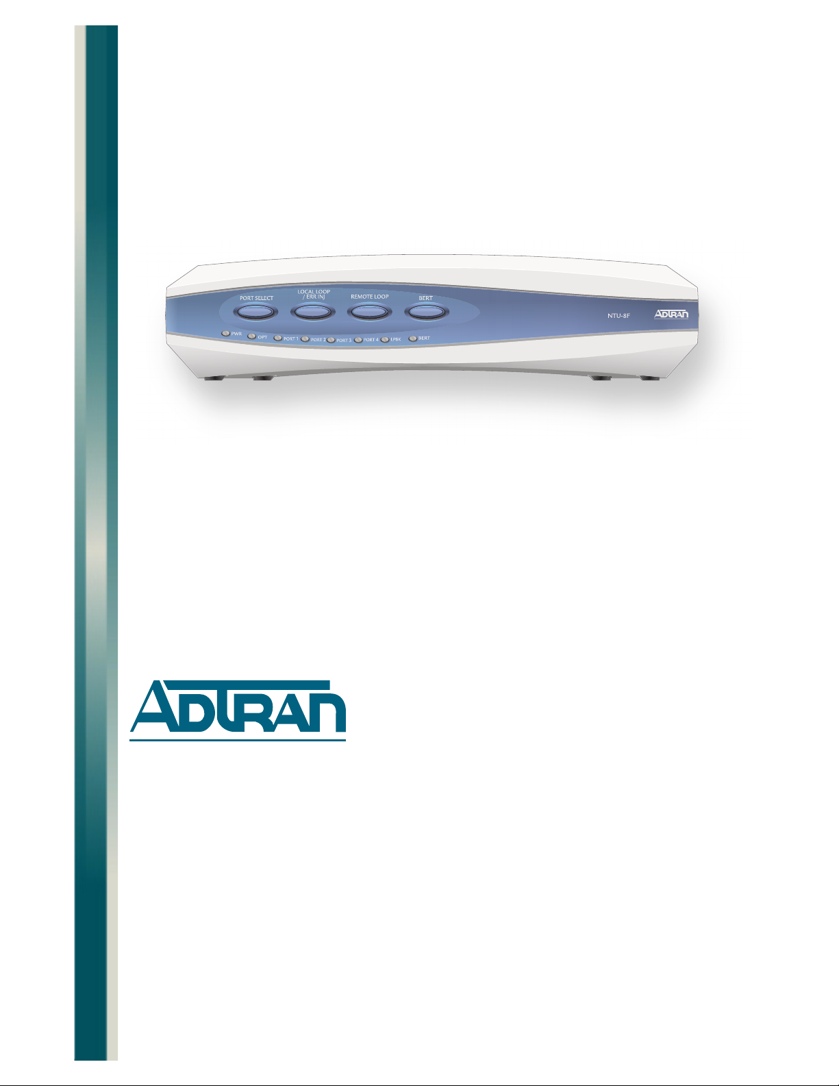
This document is an installation and maintenance guide for the Total Access® 3000/3010
NTU-8 Single Fiber Quad E1 with Ethernet and Performance Monitoring (NTU-8F). Figure 1
illustrates the NTU-8F (P/N 1182301E1) front panel.
Figure 1. NTU-8F Front Panel
DESCRIPTION
The NTU-8F is a standalone remote network terminal unit that provides for transport four,
short-haul E1 (G.703) channels, and a 10Base-T or 100Base-T (10/100) Ethernet interface
that can be multiplexed over a single-mode fiber optic cable to a Total Access 3000/3010 LTU8 Single Fiber Quad E1 with Ethernet and Performance Monitoring (P/N 1182300E1). The
LTU-8 is located in the Central Office. The NTU-8F is provisionable remotely from the LTU-8.
Provisioning can be viewed locally and flash upgrades can be initiated by using a VT100 craft
interface.
Features
The basic features of the Total Access 3000/3010 NTU-8F include the following:
• E1 Status for all channels
• Loopback Status
• Optical port status
61182301E1-5A 1
Page 8

Total Access 3000/3010 NTU-8 Single Fiber Quad E1 Installation and Maintenance Practice
• Operation over extended temperature range of –5°C to +55°C
• Optical interface consisting of a single mode transceiver module comprised of a single fiber
transmitter and an SC connector
• Optical interface port support for flat SC-type optical connectors
• Single fiber optical interface
• Operating wavelengths of 1310 nm and 1550 nm for both receiver and transmitter
Compliance
The NTU-8F is compliant with UL 60950 and IEC-60825 Class 1. The NTU-8F is also
compliant with 21CFR 1040.10 and 1040.11 except for deviations pursuant to Laser Notice
No. 50, dated July 26, 2001. The NTU-8F is intended for use in restricted access locations
only. Table 1 shows the compliance codes for the NTU-8F.
Table 1. Compliance Codes
Code Input Output
Power Code (PC) F C
Telecommunication Code (TC) – –
Installation Code (IC) A –
The G.703 interfaces for the NTU-8 Single Fiber Quad E1 are to be connected to intra-building
wiring only.
The LTU-8 is designed to meet the following environmental classes:
• ETSI EN 300 019-1-1 “Classification of environmental conditions; Storage,” Class 019-1-1,
Class 1.2
• ETSI EN 300 019-1-2 “Classification of environmental conditions; Transportation,” Class
019-1-2, Class 1.3
• ETSI EN 300 019-1-3 “Classification of environmental conditions; Stationary Use at Weather-Protected Locations,” Class 019-1-3, Class 3.3
This equipment is designed to function without degradation during exposure to all test
severities per Class 019-1-3 or 4, Class 3.3
• ETS 300 753 “Acoustic Noise Emitted by Telecommunications Equipment: Declared noise
emissions in accordance with ISO 9296 and ISO 7779:
– The Operating and Idling Sound Power (L
pressure (L
) are not applicable for this equipment, since this equipment does not
pAm
and the Operating and Idling sound
WAd)
generate noise.
2 61182301E1-5A
Page 9

INSTALLATION
C A U T I O N !
SUBJECT TO ELECTROSTATIC DAMAGE
OR DECREASE IN RELIABILITY.
HANDLING PRECAUTIONS REQUIRED.
Electrostatic Discharge (ESD) can damage electronic modules.
When handling modules, wear an antistatic discharge wrist strap
to prevent damage to electronic components. Place modules in
antistatic packing material when transporting or storing. When
working on modules, always place them on an approved antistatic
mat that is electrically grounded.
Installation
CAUTION
After unpacking the NTU-8F, inspect it for damage. If damage has occurred, file a claim with
the carrier then contact ADTRAN Customer Service. Refer to ”Appendix A, Warranty” for
further information. If possible, keep the original shipping container for returning the NTU-8F
for repair or for verification of shipping damage.
Shipping Contents
The contents include the following items:
•NTU-8F
• Total Access 3000/3010 NTU-8 Single Fiber Quad E1 with Ethernet and Performance
Monitoring Compliance Document (P/N 61182301E1-17)
• Total Access 3000/3010 NTU-8 Single Fiber Quad E1 with Ethernet and Performance
Monitoring Job Aid (P/N 61182301E1-22)
Power Interface
The power for the NTU-8F can be supplied through a –48 VDC supply connected to the
backplane of the NTU-8F. The NTU-8F operates within a voltage range of –42 VDC to –56 VDC.
Loop Connections
The E1 loop connections are made through four RJ-45 type connectors. For each connector,
transmit tip and ring are on pins 5 and 4, and receive tip and ring are on pins 2 and 1, respectively. Single-mode fiber is connected to the SC connector located on the back panel of the
module.
61182301E1-5A 3
Page 10

Total Access 3000/3010 NTU-8 Single Fiber Quad E1 Installation and Maintenance Practice
Physical Installation
To install the NTU-8F, perform the following steps:
1. Place the unit in a location where a DC power source is available. This unit operates
within a voltage range of –24 VDC to –48 VDC. If a wall-mount installation is required,
attach the supplied hangers to the unit.
2. Connect power to the NTU-8F housing. Power is connected to the NTU-8F by connecting
the plus (+), minus (–), and ground wires to a three-position terminal block located at the
right of the backplane (see Figure 2).
Figure 2. NTU-8F Rear Panel
When the NTU-8F first powers up, it runs power up self-tests. Once the power up self-test is
complete, the status LEDs will reflect the true state of the hardware.
Front Panel LEDs
The NTU-8F provides front panel LEDs to display status information. The NTU-8F LEDs and
status descriptions are shown in Table 2.
Table 2. Front Panel LEDs
Label Status Description
PWR
OPT
{
z
z
{
z
z
Off
Green
Yellow
Off
Green
Red
Power supply or fuse failure
In Service
Out of Service-Unassigned or Maintenance
Unit is Out of Service-Unassigned
Unit is active and optical interface is synchronized
Unit is active, but Rx loss on the optical interface
PORT 1-4
4 61182301E1-5A
{
z
z
z
Off
Green
Yellow
Red
Port is provisioned Out of Service-Unassigned
Port is provisioned and functioning properly
Port is in loopback or a BERT is active
Port is active with an active major alarm condition
Page 11

Table 2. Front Panel LEDs (Continued)
Label Status Description
Installation
LBK
BERT
{
z
z
z
{
z
z
z
Off
Green
Yellow
Red
Off
Green
Yellow
Red
No loopback on selected channel
Selected G.703 E1 port in local loopback
Selected G.703 E1 port in remote loopback (PN127 or V.54)
Selected G.703 E1 port in local or remote loopback (PN127 or
V.54); when no port is selected, this becomes an OR’d
summation of all loopbacks on all ports
Selected G.703 E1 port BERT not active
Selected G.703 E1 port BER, with no errors
Selected G.703 E1 port BERT active with errors
Selected G.703 E1 port active, but not in sync
Rear Panel Connections
Connectors on the rear panel (Table 3) provide for the following connections:
Table 3. Rear Panel Connectors
Connector Typ e Function
Fiber Optic SC-type Optical Connect single-mode fiber (1310 nm transmit;
1510 nm receive)
Port 1-4 RJ-45 Connect four G.703 E1s
ENET CAT 5 Modular Jack Connect 10/100 Ethernet
Craft DB-8 (RS-232) used to view menus and upgrade the NTU-8F; No
provisioning or testing can be initiated
External Alarms DB-15 Connect to six external alarm inputs
–48V, 250 mA 4-pin Terminal Block Connect to power (NTU-8F has a detachable
mating terminal screw block)
Figure 3 displays the NTU-8F Rear Panel connections.
Figure 3. NTU-8F Rear Panel Connections
61182301E1-5A 5
Page 12

Total Access 3000/3010 NTU-8 Single Fiber Quad E1 Installation and Maintenance Practice
PROVISIONING
The NTU-8F is automatically configured to match the LTU-8 settings and does not require local
provisioning. Provisioning for the LTU-8 is via the Total Access 3000/3010 System Controller
Unit (SCU). The SCU initiates and controls the transfer of commands and data to and from the
LTU-8. The LTU-8 generates all menu items for both the LTU-8 and the NTU-8F. The LTU-8
retains provisioning data in a nonvolatile memory device in the event of power loss.
Viewing of all provisionable settings, status, and Performance Monitoring menus are supported
from the NTU-8F local craft port, labeled
a DB-9 connector that supplies an RS-232 interface for connection to a controlling terminal.
The supported terminal type is VT100 or compatible and is set for the following:
• 38400 bps
• 8-data bits
•no parity
• no flow control
•1-stop bit
Y-Modem flash upgrade is password protected from the NTU-8F. The default password is
“password,” which can be changed from the NTU-8F.
CRAFT, but changes cannot be made. The craft port is
Provisioning Defaults
On initial installation, the NTU-8F is set to factory default provisioning options. Table 4 list
available options, with the default settings shown in bold type.
Table 4. Provisioning Defaults
NTU-8F Settings Defaults
Card Service State In Service;
Out of Service-Maintenance;
Out of Service Unassigned
NTU Push Buttons Disabled;
Enabled
External Alarms Disabled;
Enabled
Change NTU Firmware
Upgrade Password
Port Service State In Service;
password password
Out of Service-Maintenance;
Out of Service-Unassigned
Out of Service-Maintenance
Disabled
Disabled
Out of Service-Maintenance
E1 Frame Format FAS;
FAS+CRC4
E1 Data Rate 0h - FFh FFh
Timeslot Idle Pattern 00h - FFh FFh
6 61182301E1-5A
FAS
Page 13

Table 4. Provisioning Defaults (Continued)
NTU-8F Settings Defaults
Provisioning
LT Clock Source Internal Clock;
G.703 Rx Clock;
Fiber Rx Clock
NT Clock Source Internal Clock;
G.703 Rx Clock;
Fiber Rx Clock
ISDN-PRA V3 Disabled;
Enabled
LTU Ethernet Service State In Service;
Out of Service-Maintenance;
Out of Service-Unassigned
NTU Ethernet Service State In Service;
Out of Service-Maintenance;
Out of Service-Unassigned
Ethernet Auto Negotiation Disabled;
Enabled
Ethernet Duplex Mode Half Duplex;
Full Duplex
Ethernet Speed 10 Mbps;
100 Mbps
G.703 Rx Clock
Fiber Rx Clock
Disabled
Out of Service-Maintenance
Out of Service-Maintenance
Enabled
Full Duplex
100 Mbps
Fiber PM Thresholds Disabled Disabled
E1 PM Threshold - ES Disabled Disabled
61182301E1-5A 7
Page 14

Total Access 3000/3010 NTU-8 Single Fiber Quad E1 Installation and Maintenance Practice
OPERATION
The NTU-8F provides a platform to exchange data between four G.703 interfaces and an
optical fiber interface. The customer data connection is via the RJ-45 connector on the unit.
An optical fiber interface is provided for communication with the loop. The NTU-8F operates
with an LTU-8 at the other end of the fiber optic cable.
FRONT PANEL PUSHBUTTON
Pushbuttons on the front panel (Table 5) provide the following functionality (when the option
is enabled on the LTU-8).
Table 5. Front panel Pushbuttons
Pushbutton Function
Port Select Press the PORT SELECT button to select the active port. Selection
Local Loop/ERR INJ With a port selected, and a Bit Error Rate Test (BERT) is not in
Remote Loop With a port selected, press the REMOTE LOOP button to place or
BERT With a port selected, and no local loops, press the BERT button to
choices cycle through the provisioned G.703 E1 ports in following
order:
No Port, Port 1, Port 2, Port 3, and Port 4.
progress, press the
terminate a local loop on the selected port.
If a BERT is in progress, press the button to inject a single bit error.
remove a remote loop on the selected port's single data service. This
action sends respective inband loop-up or loop-down patterns to
the far end (in the associated data service timeslots).
start or stop a BERT on the selected port.
LOCAL LOOP/ERR INJ button to either initiate or
8 61182301E1-5A
Page 15

SPECIFICATIONS
Specifications for the NTU-8F are detailed in Table 6.
Specifications
Specification Description
Maximum Current Draw:
Maximum Power Dissipation:
Table 6. NTU-8F Specifications
Environmental
Operating Temperature:
Storage Temperature:
Relative Humidity:
Dimensions:
Weight:
Input Voltage Range:
Fiber Type:
Wave length:
Optical Budget:
Transmit Level:
Receive Level:
Connector:
–5°C to +55°C
–40°C to +85°C
Up to 95% noncondensing
Physical
Height: 1.8 inches
Width: 8.0 inches
Depth: 9.0 inches
2.5 pound
Power
–42 VDC to –56 VDC inputs
90 mA at –48 VDC
4.32 watts
Optical
Single Mode
1310 nm receive and 1550 nm transmit
17 +
1 dB
–14 +
–31 +
Single SC connector
1 dB (worst case)
1 dB (worst case)
Connectors
E1 Interface:
Fiber:
Part Number
NTU-8 Single Fiber Quad E1: 1182301E1
Compliance
Agency Approval: UL 60950
61182301E1-5A 9
RJ-45
Flat SC adapter
Page 16

Total Access 3000/3010 NTU-8 Single Fiber Quad E1 Installation and Maintenance Practice
This page is intentionally blank.
10 61182301E1-5A
Page 17

Appendix A
Warranty
WARRANTY AND CUSTOMER SERVICE
ADTRAN will replace or repair this product within the warranty period if it does not meet its
published specifications or fails while in service. Warranty information can be found at
www.adtran.com/warranty
Refer to the following subsections for sales, support, Customer and Product Service (CAPS)
requests, or further information.
ADTRAN Sales
Pricing/Availability:
800-827-0807
.
ADTRAN Technical Support
Pre-Sales Applications/Post-Sales Technical Assistance:
800-726-8663
Standard hours: Monday - Friday, 7 a.m. - 7 p.m. CST
Emergency hours: 7 days/week, 24 hours/day
ADTRAN Repair/CAPS
Return for Repair/Upgrade:
(256) 963-8722
Repair and Return Address
Contact CAPS prior to returning equipment to ADTRAN.
ADTRAN, Inc.
CAPS Department
901 Explorer Boulevard
Huntsville, Alabama 35806-2807
61182301E1-5A A-1
Page 18

®
Carrier Networks Division
901 Explorer Blvd.
Huntsville, AL 35806
 Loading...