

Page 1

Express 3000
Part Number 1203153L2
Document Number 61203153L2-20A
May 1999
1203153L2 Express 3000, Two Phone Ports
336012VUR01 Express 3000 Power Supply, 12 VDC Output
Page 2

Trademarks
Expert ISDN is a trademark of ADTRAN, Inc. (patent #5,715,241). Express
3000 and Express Configuration Software are trademarks of ADTRAN, Inc.
Hayes is a registered trademark of Hayes Microcomputer Products, Inc.
HyperTerminal is a registered trademark of Hilgraeve, Inc.
MicroPhone Pro is a trademark of Software Ventures Corporation.
Windows is a registered trademark and Windows NT is a trademark of Mi-
crosoft Corporation.
The Express 3000 incorporates Synchronous Data Compression based on ei-
ther IBM or hi/fn proprietary intellectual property depending on the time of
manufacture. The following trademarks and copyrights are applicable:
Stacker LZS Compressio n
Copyright © 1989 Carnegie Mellon University
All rights reserved.
Redistribution and use in source and binary forms are permitted provided
that the above copyright notice and this paragraph are duplicated in all such
forms and that any document ation, advert ising material s, and other mater ials
related to such distribution and us e acknowledge that the soft ware was developed by Carnegie Mellon University. The name of the University may not be
used to endorse or promote products derived from this softw are without specific prior written permission. This software is provided “as is” and without
any express or implied wa rra nt ies, including, without l imitat ion, t he implied
warranties of merchantability and fitness for a particular purpose.
hi/fn
5993 Avenida Encinas
Carlsbad, CA
Explorer Boulevard
P.O. Box 140000
Huntsville, AL 35814-4000
Phone: (256) 963-8000
© 1999 ADTRAN, Inc.
All rights reserved.
Printed in USA.
Page 3

ADTRAN Year 2000 (Y2K) Readiness Disclosure
ADTRAN has established a Year 2000 program to ensure that our
products will correctly function in the new millennium. ADTRAN
warrants that all products meet Year 2000 specifications regardless of
model or revision. Information about ADTRAN's Year 2000 compliance program is available at the following:
Product Matrix
www.adtran.com/y2kfax.html
Lists Y2K plans and product certifications.
E-mail
Faxback
Document Line
Y2K Project
year2000@adtran.com
(256) 963-8200
See also Product Matrix, above.
(256) 963-2200
Line
Important Safety Instructions
When using your telephone equipment, basic safety precautions
should always be followed to reduce the risk of fire, electric shock and
injury to persons. These precautions are listed below.
1. Do not use this product near water (for example, near a bath tub,
wash bowl, kitchen sin k or laundry tub, in a wet basement, or near
a swimming pool).
2. Avoid using a telephone (other than a cordless type) during an
electrical storm. There may be a remote risk of electric sh ock from
lightning.
3. Do not use the telephone to report a gas leak in the vicinity of the
leak.
4. Use only the power cord or power supply indicated in the manual. Check local codes for any special disposal instructions.
SAVE THESE INSTRUCTIONS
.
iii
Page 4

FCC regulations require that the following information be
provided in this manual:
1. This equipment complies with Part 68 of the FCC rules. On the
bottom of the equipment housing is a label that shows the FCC
registration number and Ringer Equivalence Number (REN) for
this equipment. If requested, provide this information to the telephone company.
2. If this equipment causes harm to the telephone network, the telephone company may temporarily discontinue service. If possible,
advance notification is given; otherwise, notification is given as
soon as possible. The telephone company will advise the customer of the right to file a complaint with the FCC.
3. The telephone company may make changes in its facilities, equipment, operations, or procedures that could affect the proper operation of this equipment; advance notification and the opportunity
to maintain uninterrupted service is given.
4. If experiencing difficulty with this equipment, please contact
ADTRAN for repair and warranty information. The telephone
company may require this equipment to be disconnected from the
network until the problem is corrected or it is certain the equipment is not malfunctioning.
5. This unit contains no user-serviceable parts.
6. An FCC-compliant telephone cord with a modular plug is provided with this equipment. This equipment is designed to be connected to the telephone network or premises wiring using an FCCcompatible modular jack, which is Part 68 compliant.
7. The following information may be required when applying to the
local telephone company for leased line facilitie s.
iv
Service
Type
Digital Facility
Interface Code
Service Ord er
Code
Network Jacks
ISDN 021S5 6.0F RJ-45
Page 5

Federal Communications Commission Radio Frequency
Interference Statement
This equipment has been tested and found to comply with the limits
for a Class B digital device, pursuant to Part 15 of the FCC Rules. These
limits are designed to provide reasonable protection against harmful
interference when the equipment is operated in a commercial environment. This equipment generates, uses, and can radiate radio frequency energy and, if not installed and used in accordance with the
instructions, may cause harmful interference to TV or radio reception,
which can be determined by turning the equipment on and off. The
user is encouraged to try to correct the interference by one or more of
the following methods:
• Reorient or relocate the receiving antenna.
• Increase the separation between the equipment and receiver.
• Connect the equipment into an outlet on a circuit different from
that to which the receiver is connected.
• Consult the dealer or an experienced radio/TV technician for
help.
Changes or modifications to this unit not expressly
approved by ADTRAN will void the user’s auth ority
to operate the equipment.
Canadian Emissions Requirements
This digital apparatus does not exceed the Class B limits for radio
noise emissions from digital apparatus as set out in the interferencecausing equipment standard entitled “Digital Apparatus,” ICES-003
of the Department of Communications.
Cet appareil nuerique respecte les limites de bruits radioelectriques
applicables aux appareils numeriques de Class B prescrites dans la
norme sur le materiel brouilleur: “Appareils Numeriques,” NMB-003
edictee par le ministre des Communications.
v
Page 6

Canadian Equipment Limitations
NOTICE:
The Canadian Industry and Science Canada label identifies
certified equipment. This certification means that the equipment
meets certain telecommunications network protective, operational,
and safety requirements. The Department of Communications does
not guarantee the equipment will operate to the user’s satisfaction.
Before installing this equipment, users should ensure that it is permissible to be connected to the facilities of the local telecommunica tions
company. The equipment must also be install ed us ing an acceptable
method of connection. In some cases, the company’s inside wiring associated with a single line individual service may be extended by
means of a certified connector assembly (telephone extension cord).
The customer should be aware that compliance with the above con ditions may not prevent degradation of service in some situations.
Repairs to certified equipment should be made by an authorized Canadian maintenance facility designated by the supplier. Any repairs
or alterations made by the user to this equipment, or equipment malfunctions, may give the telecommunications co mpany cause to request the user to disconnect the equipment.
Users should ensure for their own protection that the electrical ground
connections of the power utility, telephone lines, and internal metallic
water pipe system, if present, are connected together. This precaution
may be particularly important in rura l areas.
Users should not attempt to make such connections themselves,
but should contact the appropriate electric inspection authority,
or an electrician, as appropriate.
The Load Number (LN) assigned to each terminal device denotes the
percentage of the total load to be connected to a telephone loop which
is used by the device, to prevent overloading. The termination on a
loop may consist of any combination of devices subject only to the requirement that the total of the Load Numbers of all devices does not
exceed 100.
vi
Page 7

WARRANTY:
ADTRAN warrants that items manufactured by
ADTRAN and supplied under Buyer’s order shall be f ree from defects
in materials and workmanship and will conform to applicable
specifications and drawings. ADTRAN’s liability herein, whether
based upon breach of warranty or contract or negligence in
manufacture, shall be limited to replacement or repair at ADTRAN’s
election of all such defective or nonconforming items, provided that
this warranty shall apply only where Buyer has given ADTRAN
written notice of such defects or nonconformity within five (5) years*
after delivery by ADTRAN of such items to Buyer. ADTRAN shall
have the right prior to return to inspect at Buyer’s plant any items
claimed to be defective or nonconforming.
*Note:
The following items carry warranty period as shown.
1. Items not of ADTRAN manufacture will carry the remaining war-
ranty and related terms and conditions of the original manufacturer.
2. Encapsulated U-Repeater and Encapsulated DDS Repeater—two
years.
The foregoing constitutes the sole and exclusive remedy of the Buyer
and exclusive liability of ADTRAN AND IS IN LIEU OF ANY AND
ALL OTHER WARRANTIES EXPRESSED OR IMPLIED OR STATUTORY AS TO MERCHANTABILITY, FITNESS FOR PURPOSE SOLD,
DESCRIPTION, QUALITY, PRODUCTIVENESS OR ANY OTHER
MATTER. Without limiting the foregoing, in no event shall ADTRAN
be liable for the loss of use or profit or other collateral, special or consequential damages.
RETURNS:
Return authorization must be obtained from ADTRAN
prior to return of any items, including those for repair. Buyer’s right
to repair or replacement is governed by this Warranty. Issuance of
credit for returned items shall be made at ADTRAN’s discretion upon
Buyer’s request. All returns for credit accepted by ADTRAN are subject to a restocking fee.
SHIPPING:
The cost of shipping the equipment from Buyer’s facility
back to ADTRAN shall be paid by the Buyer. The cost for return shipping of the equipment by surface carrier shall be paid by ADTRAN.
ADTRAN will utilize other means of express shipment at the request
of the Buyer. The cost of shipping shall be paid by the Buyer if express
vii
Page 8

shipment is requested. In-warranty equipment returned for repair
that is found not defective will carry a nominal charge to cover handling cost.
OUT OF WARRANTY:
The cost of out-of-warranty repairs including return shipment are subject to a charge as quoted by ADTRAN. The cost
of the repair will be invoiced and the return of the item will be made
using the most economical shipment means available. ADTRAN will
use other means of express shipment at the request of the Buyer. In
this case, the cost of shipping shall be paid by the Buyer.
ALTERATION TO EQUIPMENT PURCHASED:
Modification or alteration to purchased equipment by Buyer, other than that specifically
authorized by this Agreement or by ADTRAN, shall VOID AND
NULLIFY, in its entirety, all warranty conditions as set forth in Warranty paragraph.
ENGINEERING CHANGES:
ADTRAN reserves the right to make
progress and design changes in standard pro duct items ordered wi thout prior approval or notification to Buyer and without incurring any
obligations or liability to make the same changes in items previously
manufactured.
DATA RIGHTS:
Rights to any intellectual property residing in the
products or any data furnished hereunder are not granted except by
specific written permission by an authorized representative of
ADTRAN. Buyer shall have no right to copy or reproduce in whole or
part any data furnished hereunder without the prior written consent
of ADTRAN.
PATENT AND COPYRIGHT INDEMNITY:
ADTRAN warrants that the
equipment and documentation furnished under this Agreement shall
be free and clear of infringement of any patent or copyright covering
the structure or composition of such articles or documentation. In the
event of a claim, suit, or action against Buyer alleging such
infringement, ADTRAN shall save Buyer and its affiliates, agents or
customers harmless from liability as finall y det e rmined by a court of
competent jurisdiction, for such infringement, provided that Buyer
gives ADTRAN notice promptly of such claim, suit, or action, and
shall have given ADTRAN full and exclusive control of the defense
thereof, and that ADTRAN shall have sole right to settle or
compromise such claim, suit, or action.
viii
Page 9

In the event of a claim, suit or action against ADTRAN alleging
infringement by the use of any such equipment or documentation,
furnished under this Agreement, in combination with other articles or
in carrying out any process covered by a patent owned or controlled
by any other person, in which independent use of the equipment
under this Agreement would not be an infringement. Buyer sha ll save
ADTRAN harmless from liability, as finally determined by a court of
competent jurisdiction, for such infringement, provided that
ADTRAN shall have given Buyer full and exclusive control of the
defense thereof, and that Buyer shall have the sole right to settle claim,
suit or action.
Except as herein provided in this indemnity paragraph, neither Buyer
nor ADTRAN makes any warranty to the other with respect to any
claim, suit or action of any third party by way of infringement and neither party shall be responsible to the other for any loss, cost o r damages consequential or otherwise, that may be suffered by the other as a
result of any such claim, suit or action .
Telephone Company Contacts for ISDN Service
Ameritech ISDN Repair
Bell Atlantic South
Bell South
Cincinnati Bell
Bell Atlantic North
Pac Bell
Rochester Tel
Southwestern Bell
US West
1-800-TEAMDATA
1-800-570-ISDN
1-800-247-2020
1-513-241-6900
1-800-GET-ISDN
1-800-430-ISDN (New England Area)
1-800-4PB-ISDN
1-716-777-1811 (Repair)
1-716-777-2000 (Order)
1-800-792-4736
1-800-223-7508 (Repair)
1-800-244-1111 (Order)
ix
Page 10

Affidavit Requirements for Connection to Digital Services
• An affidavit is required to be given to the telephone company
whenever digital terminal equipment without encoded analog
content and billing protection is used to transmit digital signals
containing encoded analog content which are intended for eventual conversion into voiceband analog signals and transmitted on
the network.
• The affidavit shall affirm that either no encoded a nalog content or
billing information is being tran smitted or that the output of the
device meets Part 68 encoded analog content or billing protection
specifications.
• End user/customer will be responsible to file an affidavit with the
local exchange carrier when connecting unprotected Customer
Premises Equipment (CPE) to 1.544 Mbps or subrate digital services.
• Until such time as subrate digital terminal equipment is registered
for voice applications, the affidavit requirement for subrate services is waived.
Affidavit for Connection of Customer Premises Equipment to
1.544 Mbps and/or Subrate Digital Services
For the work to be performed in the certified territory of
_________________________________ (telco name)
State of __________________________
County of ________________________
I, _______________ __ ___ ___________ (name),
_________________________________ (business address),
_________________________________ (telephone number)
being duly sworn, state:
I have responsibility for the operation and maintenance of the termi-
nal equipment to be connected to 1.544 Mbps and/or ________ subrate
digital services. The terminal equipment to be connected com p lies
with Part 68 of the FCC rules except for the encoded analog content
and billing protection specifications. With respect to encoded analog
content and billing protection:
x
Page 11

( ) I attest that all operations associated with the establishment, maintenance, and adjustment of the digital CPE with respect to analog content and encoded billing protection information continuously
complies with Part 68 of the FCC Rules and Regulations.
( ) The digital CPE does not transmit digital signals containing encoded analog content or billing information which is intended to be
decoded within the telecommunications network.
( ) The encoded analog content and billing protection is factory set
and is not under the control of the customer.
I attest that the operator(s)/maintainer(s) of the digital CPE responsible for the establishment, maintenance, and adjustment of the encoded analog content and billing information has (have) been trained to
perform these functions by successfully having completed one of the
following (check appropriate blocks):
( ) A. A training course provided by the manufacturer/grantee of the
equipment used to encode analog signals; or
( ) B. A training course provided by the customer or authorized representative, using training materials and instructions provided by the
manufacturer/grantee of the equipment used to encode analog signals; or
( ) C. An independent training course (e.g., trade school or technical
institution) recognized by the manufacturer/grantee of the equipment used to encode analog signals; or
( ) D. In lieu of the preceding training requirements, the operator( s)/
maintainer(s) is (are) under the control of a supervisor trained in accordance with _________ (circle one) above.
I agree to provide _________________ (telco' s name) wi th proper documentation to demonstrate compliance with the information as provided in the preceding paragraph, if so requested.
_______________ ___ _______________Signature
_______________ ___ _______________Title
_________________________________ Date
Transcribed and sworn to before me
This ________ day of ________, ________
_________________________________
Notary Public
My commission expires:
_________________________________
xi
Page 12

xii
Page 13

Table of Contents
List of Figures . . . . . . . . . . . . . . . . . . . . . . . . . . . . . . . . . . . . . . . . . . .xix
List of Tables . . . . . . . . . . . . . . . . . . . . . . . . . . . . . . . . . . . . . . . . . . . .xxi
Chapter 1 Overview. . . . . . . . . . . . . . . . . . . . . . . . . . . . . . . . . . . . .1-1
AO/DI . . . . . . . . . . . . . . . . . . . . . . . . . . . . . . . . . . . . . . . . . . . . . . . . . .1-1
Express Configuration Software . . . . . . . . . . . . . . . . . . . . . . . . . . . .1-1
Analog Devices Supported. . . . . . . . . . . . . . . . . . . . . . . . . . . . . . . . .1-2
Remote Access . . . . . . . . . . . . . . . . . . . . . . . . . . . . . . . . . . . . . . . . . . . 1-2
Express 3000 Features . . . . . . . . . . . . . . . . . . . . . . . . . . . . . . . . . . . . .1-2
System Requirements . . . . . . . . . . . . . . . . . . . . . . . . . . . . . . . . . . . . .1-3
Ordering a Basic Rate ISDN Line . . . . . . . . . . . . . . . . . . . . . . . . . . .1-4
Express 3000 Shipping Contents . . . . . . . . . . . . . . . . . . . . . . . . . . . .1-4
Additional Documentation. . . . . . . . . . . . . . . . . . . . . . . . . . . . . . . . .1-4
Chapter 2 Setting Up the Express 3000 . . . . . . . . . . . . . . . . . . . .2-1
Windows Installation Procedure. . . . . . . . . . . . . . . . . . . . . . . . . . . .2-2
Connecting the Hardware: Windows . . . . . . . . . . . . . . . . . . . . . .2-2
Installing the Express 3000: Windows 95/98 . . . . . . . . . . . . . . .2-3
Installing the Express Configuration Software: Windows . . . .2-4
Installing the Express 3000: Windows NT . . . . . . . . . . . . . . . . . .2-4
Macintosh Installation Procedure . . . . . . . . . . . . . . . . . . . . . . . . . . .2-5
Connecting the Hardware: Macintosh . . . . . . . . . . . . . . . . . . . . .2-6
Installing the Express Configurati on Software: Macintosh . . .2-7
Express 3000 Physical Description . . . . . . . . . . . . . . . . . . . . . . . . . .2-7
Front Panel . . . . . . . . . . . . . . . . . . . . . . . . . . . . . . . . . . . . . . . . . . . .2-7
Rear Panel . . . . . . . . . . . . . . . . . . . . . . . . . . . . . . . . . . . . . . . . . . . . .2-8
Setting the DIP Switches . . . . . . . . . . . . . . . . . . . . . . . . . . . . . . .2-9
DIP Switch 1 . . . . . . . . . . . . . . . . . . . . . . . . . . . . . . . . . . . . . . . . .2-9
DIP Switch 2 . . . . . . . . . . . . . . . . . . . . . . . . . . . . . . . . . . . . . . . . .2-9
Using Supplemental Analog Devices . . . . . . . . . . . . . . . . . . . . . . .2-10
Connecting Supplemental Devices . . . . . . . . . . . . . . . . . . . . . . . . .2-10
Connecting Your Primary Telephone . . . . . . . . . . . . . . . . . . . . .2-11
61203153L2-20 Express 3000 User Manual xiii
Page 14

Table of Contents
Shared Port for Analog Devices . . . . . . . . . . . . . . . . . . . . . . . . . 2-11
Chapter 3 Using the Express Configuration Program . . . . . . . 3-1
Before Using the Program . . . . . . . . . . . . . . . . . . . . . . . . . . . . . . . . . 3-2
Opening the Program. . . . . . . . . . . . . . . . . . . . . . . . . . . . . . . . . . . . . 3-2
Instructions for Windows 95, 98, and NT . . . . . . . . . . . . . . . . . . 3-2
Closing The Program . . . . . . . . . . . . . . . . . . . . . . . . . . . . . . . . . . . . . 3-3
Launching the Tray Tool . . . . . . . . . . . . . . . . . . . . . . . . . . . . . . . . . . 3-3
Instructions for Macintosh . . . . . . . . . . . . . . . . . . . . . . . . . . . . . . 3-3
Opening the Tray Tool Menu . . . . . . . . . . . . . . . . . . . . . . . . . . . . 3-4
Properties . . . . . . . . . . . . . . . . . . . . . . . . . . . . . . . . . . . . . . . . . . . 3-4
Toll Saver . . . . . . . . . . . . . . . . . . . . . . . . . . . . . . . . . . . . . . . . . . . 3-4
Refresh . . . . . . . . . . . . . . . . . . . . . . . . . . . . . . . . . . . . . . . . . . . . . 3-4
Enable/Disable Modem . . . . . . . . . . . . . . . . . . . . . . . . . . . . . . . 3-4
Capture COM Port . . . . . . . . . . . . . . . . . . . . . . . . . . . . . . . . . . . 3-4
About Express Configuration . . . . . . . . . . . . . . . . . . . . . . . . . . 3-4
Help on Express Configuration . . . . . . . . . . . . . . . . . . . . . . . . 3-4
Exit . . . . . . . . . . . . . . . . . . . . . . . . . . . . . . . . . . . . . . . . . . . . . . . . . 3-4
Factory Default settings . . . . . . . . . . . . . . . . . . . . . . . . . . . . . . . . . . . 3-5
Restoring Factory Default Settings . . . . . . . . . . . . . . . . . . . . . . . . 3-5
Using On-line Help. . . . . . . . . . . . . . . . . . . . . . . . . . . . . . . . . . . . . . . 3-5
Understanding Profiles . . . . . . . . . . . . . . . . . . . . . . . . . . . . . . . . . . . 3-6
ISDN Profiles . . . . . . . . . . . . . . . . . . . . . . . . . . . . . . . . . . . . . . . . . . 3-6
User Profiles . . . . . . . . . . . . . . . . . . . . . . . . . . . . . . . . . . . . . . . . . . 3-6
Internet Access Protocols . . . . . . . . . . . . . . . . . . . . . . . . . . . . . . 3-6
Remote Access Protocols . . . . . . . . . . . . . . . . . . . . . . . . . . . . . . 3-7
Using Profiles . . . . . . . . . . . . . . . . . . . . . . . . . . . . . . . . . . . . . . . . . 3-7
ISDN Profile Window . . . . . . . . . . . . . . . . . . . . . . . . . . . . . . . . . 3-7
General Tab . . . . . . . . . . . . . . . . . . . . . . . . . . . . . . . . . . . . . . . 3-8
Switch Type . . . . . . . . . . . . . . . . . . . . . . . . . . . . . . . . . . . . . 3-8
Area Code . . . . . . . . . . . . . . . . . . . . . . . . . . . . . . . . . . . . . . . 3-8
Phone Numbers 1and 2 . . . . . . . . . . . . . . . . . . . . . . . . . . . . 3-9
SPIDs 1and 2 . . . . . . . . . . . . . . . . . . . . . . . . . . . . . . . . . . . . . 3-9
Disable SPID download . . . . . . . . . . . . . . . . . . . . . . . . . . . 3-9
NI1 Conference Feature . . . . . . . . . . . . . . . . . . . . . . . . . . . 3-9
NI1 Transfer Feature . . . . . . . . . . . . . . . . . . . . . . . . . . . . . 3-10
NI1 Message Feature . . . . . . . . . . . . . . . . . . . . . . . . . . . . . 3-10
Packet Tab . . . . . . . . . . . . . . . . . . . . . . . . . . . . . . . . . . . . . . . . 3-10
xiv Express 3000 User Manual 61203153L2-20
Page 15

Table of Contents
TX Window Size . . . . . . . . . . . . . . . . . . . . . . . . . . . . . . . . .3-10
RX Window Size . . . . . . . . . . . . . . . . . . . . . . . . . . . . . . . . .3-10
Packet Size . . . . . . . . . . . . . . . . . . . . . . . . . . . . . . . . . . . . . .3-10
Packet DN . . . . . . . . . . . . . . . . . . . . . . . . . . . . . . . . . . . . . .3-10
Packet TEI . . . . . . . . . . . . . . . . . . . . . . . . . . . . . . . . . . . . . .3-10
Dial Prefix . . . . . . . . . . . . . . . . . . . . . . . . . . . . . . . . . . . . . .3-10
Preview Tab . . . . . . . . . . . . . . . . . . . . . . . . . . . . . . . . . . . . . .3-11
User Profile Window . . . . . . . . . . . . . . . . . . . . . . . . . . . . . . . . .3-11
General Tab . . . . . . . . . . . . . . . . . . . . . . . . . . . . . . . . . . . . . . .3-12
Protocol . . . . . . . . . . . . . . . . . . . . . . . . . . . . . . . . . . . . . . . .3-12
PPP Mode . . . . . . . . . . . . . . . . . . . . . . . . . . . . . . . . . . . . . . .3-12
Enable Bandwidth on Demand . . . . . . . . . . . . . . . . . . . .3-12
Disable BACP . . . . . . . . . . . . . . . . . . . . . . . . . . . . . . . . . . .3-12
DTR Options . . . . . . . . . . . . . . . . . . . . . . . . . . . . . . . . . . . .3-12
Flow Control . . . . . . . . . . . . . . . . . . . . . . . . . . . . . . . . . . . .3-13
Data Call Type . . . . . . . . . . . . . . . . . . . . . . . . . . . . . . . . . . .3-13
Data Over Voice . . . . . . . . . . . . . . . . . . . . . . . . . . . . . . . . .3-14
Call Routing . . . . . . . . . . . . . . . . . . . . . . . . . . . . . . . . . . . . .3-14
Enable Distinctive Ringing . . . . . . . . . . . . . . . . . . . . . . . .3-14
Protocols Tab . . . . . . . . . . . . . . . . . . . . . . . . . . . . . . . . . . . . . .3-14
Enable AO/DI . . . . . . . . . . . . . . . . . . . . . . . . . . . . . . . . . . .3-14
Raise Threshold . . . . . . . . . . . . . . . . . . . . . . . . . . . . . . . . . .3-14
Lower Threshold . . . . . . . . . . . . . . . . . . . . . . . . . . . . . . . . .3-15
Add Time . . . . . . . . . . . . . . . . . . . . . . . . . . . . . . . . . . . . . . .3-15
Drop Time . . . . . . . . . . . . . . . . . . . . . . . . . . . . . . . . . . . . . .3-15
Available Channels . . . . . . . . . . . . . . . . . . . . . . . . . . . . . .3-15
Type . . . . . . . . . . . . . . . . . . . . . . . . . . . . . . . . . . . . . . . . . . . 3 -15
TXINIT . . . . . . . . . . . . . . . . . . . . . . . . . . . . . . . . . . . . . . . . .3-15
TXFA . . . . . . . . . . . . . . . . . . . . . . . . . . . . . . . . . . . . . . . . . . .3-15
TXADD01 . . . . . . . . . . . . . . . . . . . . . . . . . . . . . . . . . . . . . . .3-16
TXDEQ . . . . . . . . . . . . . . . . . . . . . . . . . . . . . . . . . . . . . . . . .3-16
TANULL . . . . . . . . . . . . . . . . . . . . . . . . . . . . . . . . . . . . . . .3-16
TCID . . . . . . . . . . . . . . . . . . . . . . . . . . . . . . . . . . . . . . . . . . .3-16
Phone List Tab . . . . . . . . . . . . . . . . . . . . . . . . . . . . . . . . . . . .3-16
Allow only stored numbers . . . . . . . . . . . . . . . . . . . . . . .3-16
Stored Numbers . . . . . . . . . . . . . . . . . . . . . . . . . . . . . . . . .3-16
Enable Call Rejection List . . . . . . . . . . . . . . . . . . . . . . . . .3-16
Enable Anonymous Call Rejection . . . . . . . . . . . . . . . . . .3-17
Incoming Voice Call Rejection List . . . . . . . . . . . . . . . . .3-17
61203153L2-20 Express 3000 User Manual xv
Page 16

Table of Contents
Advanced Tab . . . . . . . . . . . . . . . . . . . . . . . . . . . . . . . . . . . . 3-17
V120 Lower Layer Compatibility . . . . . . . . . . . . . . . . . . 3-17
Connect Timeout . . . . . . . . . . . . . . . . . . . . . . . . . . . . . . . . 3-17
Inactivity Timer . . . . . . . . . . . . . . . . . . . . . . . . . . . . . . . . . 3-17
Remote Password . . . . . . . . . . . . . . . . . . . . . . . . . . . . . . . . 3-17
Test Timeout . . . . . . . . . . . . . . . . . . . . . . . . . . . . . . . . . . . . 3-18
Auto Answer . . . . . . . . . . . . . . . . . . . . . . . . . . . . . . . . . . . 3-18
Disable call waiting on POTS 1 and 2 . . . . . . . . . . . . . . . 3-18
Flash/Hook Default . . . . . . . . . . . . . . . . . . . . . . . . . . . . . 3-18
Preview Tab . . . . . . . . . . . . . . . . . . . . . . . . . . . . . . . . . . . . . . 3-18
Creating New Profiles . . . . . . . . . . . . . . . . . . . . . . . . . . . . . . . . . 3-19
Saving Profiles . . . . . . . . . . . . . . . . . . . . . . . . . . . . . . . . . . . . . . . . 3-19
Modifying Profiles . . . . . . . . . . . . . . . . . . . . . . . . . . . . . . . . . . . . 3-20
Copying Profiles . . . . . . . . . . . . . . . . . . . . . . . . . . . . . . . . . . . . . . 3-20
Deleting Profiles . . . . . . . . . . . . . . . . . . . . . . . . . . . . . . . . . . . . . . 3-21
Importing Profiles . . . . . . . . . . . . . . . . . . . . . . . . . . . . . . . . . . . . . 3-22
Exporting Profiles . . . . . . . . . . . . . . . . . . . . . . . . . . . . . . . . . . . . . 3-22
Reading Configuration Informa tion into the Current Profile 3-23
Using Diagnostics . . . . . . . . . . . . . . . . . . . . . . . . . . . . . . . . . . . . . . . 3-23
Diagnosing Local Units . . . . . . . . . . . . . . . . . . . . . . . . . . . . . . . . 3-24
Displaying the Unit’s Current Status . . . . . . . . . . . . . . . . . . . 3-24
Displaying the Express 3000’s Caller ID Log Buffer . . . . . . 3-24
Retrieving Current Settings . . . . . . . . . . . . . . . . . . . . . . . . . . . 3-24
Diagnosing Connection Problems . . . . . . . . . . . . . . . . . . . . . 3-25
Launching Terminal Programs . . . . . . . . . . . . . . . . . . . . . . . . 3-25
Diagnosing Remote Units . . . . . . . . . . . . . . . . . . . . . . . . . . . . . . 3-25
Testing a Remote Unit . . . . . . . . . . . . . . . . . . . . . . . . . . . . . . . 3-25
Configuring a User Profile on a Remote Unit . . . . . . . . . . . . 3-25
Retrieving Current Settings from a Remote Unit . . . . . . . . . 3-25
Retrieving Status Buffer Information from a Remote Unit . 3-26
Customizing the ADTRAN Express Configuration program . . 3-26
Detecting the Connection . . . . . . . . . . . . . . . . . . . . . . . . . . . . . . 3-26
Automatically Detecting the Unit on Startup . . . . . . . . . . . . . . 3-27
Using Caller ID . . . . . . . . . . . . . . . . . . . . . . . . . . . . . . . . . . . . . . . 3-27
Using Terminal Software for Diagnostics . . . . . . . . . . . . . . . . . 3-27
Using the Wizard. . . . . . . . . . . . . . . . . . . . . . . . . . . . . . . . . . . . . . . . 3-28
Automatically Running the Wizard on Startup . . . . . . . . . . . . 3-30
Locating Information About the Program. . . . . . . . . . . . . . . . . . . 3-30
xvi Express 3000 User Manual 61203153L2-20
Page 17

Table of Contents
Chapter 4 Using VT-100 Terminal Emulation . . . . . . . . . . . . . .4-1
Accessing Terminal Menus . . . . . . . . . . . . . . . . . . . . . . . . . . . . . .4-2
Exiting the Terminal Menus . . . . . . . . . . . . . . . . . . . . . . . . . . . . .4-3
Placing the Unit Back On-line . . . . . . . . . . . . . . . . . . . . . . . . . . . .4-3
Displaying the Status Buffer . . . . . . . . . . . . . . . . . . . . . . . . . . . . .4-3
Status Buffer Messages . . . . . . . . . . . . . . . . . . . . . . . . . . . . . . . . . . . .4-4
Chapter 5 Optional Calling Features . . . . . . . . . . . . . . . . . . . . . .5-1
Call Conferencing . . . . . . . . . . . . . . . . . . . . . . . . . . . . . . . . . . . . . . . .5-1
Call Forwarding. . . . . . . . . . . . . . . . . . . . . . . . . . . . . . . . . . . . . . . . . .5-2
Caller ID . . . . . . . . . . . . . . . . . . . . . . . . . . . . . . . . . . . . . . . . . . . . . . . .5-2
Call Return . . . . . . . . . . . . . . . . . . . . . . . . . . . . . . . . . . . . . . . . . . . . . .5-2
Call Reject . . . . . . . . . . . . . . . . . . . . . . . . . . . . . . . . . . . . . . . . . . . . . . .5-2
Call Rejection List . . . . . . . . . . . . . . . . . . . . . . . . . . . . . . . . . . . . . .5-2
Anonymous Call Rejection . . . . . . . . . . . . . . . . . . . . . . . . . . . . . . .5-2
Call Waiting . . . . . . . . . . . . . . . . . . . . . . . . . . . . . . . . . . . . . . . . . . . . . 5-3
Controlling Call Waiting . . . . . . . . . . . . . . . . . . . . . . . . . . . . . . . .5-3
Message Waiting Indicator. . . . . . . . . . . . . . . . . . . . . . . . . . . . . . . . .5-4
POTS Ports Distinctive Rings. . . . . . . . . . . . . . . . . . . . . . . . . . . . . . .5-4
Chapter 6 Upgrading Software . . . . . . . . . . . . . . . . . . . . . . . . . . .6-1
Upgrading Files Using the Express Configuration Program . . . .6-1
Upgrading Software Using HyperTerminal . . . . . . . . . . . . . . . . . .6-3
Chapter 7 Installing an Analog Modem . . . . . . . . . . . . . . . . . . .7-1
External Analog Modem Application. . . . . . . . . . . . . . . . . . . . . . . .7-1
Connecting an External Analog Modem . . . . . . . . . . . . . . . . . . .7-3
Configuring the External Analog Modem . . . . . . . . . . . . . . . . . .7-4
Setting the Carrier Detect Signal . . . . . . . . . . . . . . . . . . . . . . . . . .7-4
Controlling an External Analog Modem . . . . . . . . . . . . . . . . . . . . .7-5
Controlling the Modem via Terminal Emulation . . . . . . . . . . . .7-5
Internal Analog Modem Application . . . . . . . . . . . . . . . . . . . . . . . .7-6
Connecting an Internal Analog Modem . . . . . . . . . . . . . . . . . . .7-7
Chapter 8 Troubleshooting . . . . . . . . . . . . . . . . . . . . . . . . . . . . . .8-1
Troubleshooting Guidelines. . . . . . . . . . . . . . . . . . . . . . . . . . . . . . . .8-1
61203153L2-20 Express 3000 User Manual xvii
Page 18

Table of Contents
Appendix A AT Commands and S-Registers . . . . . . . . . . . . . .A-1
Appendix B Status Buffer Messages . . . . . . . . . . . . . . . . . . . . . .B-1
Appendix C Loop Status Messages . . . . . . . . . . . . . . . . . . . . . . .C-1
Appendix D Connector Pinouts . . . . . . . . . . . . . . . . . . . . . . . . . D-1
Appendix E Acronyms and Abbreviations . . . . . . . . . . . . . . . .E-1
Appendix F Glossary . . . . . . . . . . . . . . . . . . . . . . . . . . . . . . . . . . . F-1
Index . . . . . . . . . . . . . . . . . . . . . . . . . . . . . . . . . . . . . . . . . . . . . .Index-1
xviii Express 3000 User Manual 61203153L2-20
Page 19

List of Figures
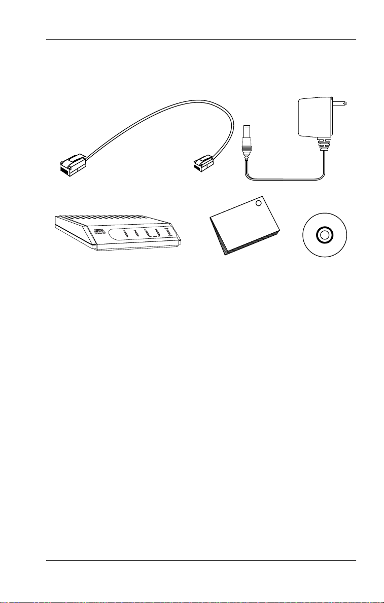
Figure 1-1. Express 3000 Contents. . . . . . . . . . . . . . . . . . . . . . . . . .1-5
Figure 2-1. Front Panel LEDs . . . . . . . . . . . . . . . . . . . . . . . . . . . . . .2-7
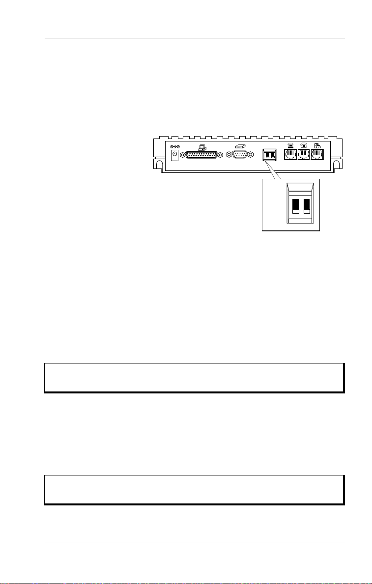
Figure 2-2. Express 3000 Rear Panel . . . . . . . . . . . . . . . . . . . . . . . .2-8
Figure 2-3. DIP Switch Locations on Rear Panel . . . . . . . . . . . . . .2-9
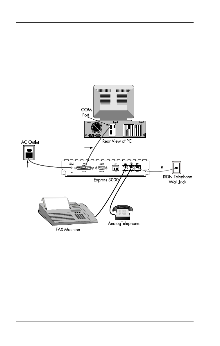
Figure 2-4. Possible Hardware Configuration . . . . . . . . . . . . . . .2-10
Figure 2-5. POTS Interfaces. . . . . . . . . . . . . . . . . . . . . . . . . . . . . . .2-11
Figure 3-1. ADTRAN Express Configuration GUI . . . . . . . . . . . .3-2
Figure 3-2. Tray Tool Icon in the Taskbar. . . . . . . . . . . . . . . . . . . .3-3
Figure 3-3. ISDN Profile Setup Window. . . . . . . . . . . . . . . . . . . . .3-8
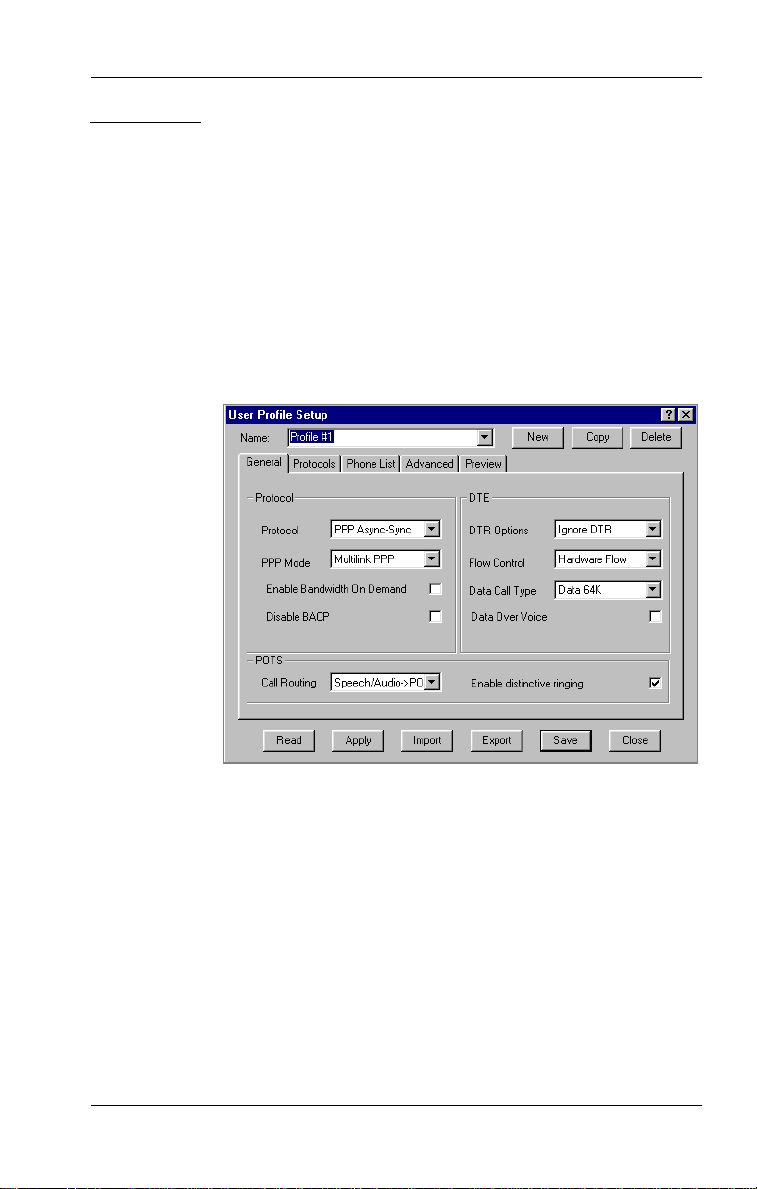
Figure 3-4. User Profile Setup Window . . . . . . . . . . . . . . . . . . . .3-11
Figure 3-5. Diagnostics Window . . . . . . . . . . . . . . . . . . . . . . . . . .3-24
Figure 3-6. Preferences Window . . . . . . . . . . . . . . . . . . . . . . . . . .3-26
Figure 3-7. ADTRAN Express Configuration Wizard . . . . . . . .3-28
Figure 3-8. Window for Entering ISDN Phone Numbers . . . . .3-29
Figure 3-9. Window for Entering SPID Numbers . . . . . . . . . . . .3-29
Figure 4-1. VT 100 Terminal Configuration Menu . . . . . . . . . . . .4-2
Figure 4-2. VT 100 Terminal Status Buffer Menu . . . . . . . . . . . . .4-3
Figure 7-1. External Analog Modem Application . . . . . . . . . . . . .7-2
Figure 7-2. Internal Analog Modem Connections. . . . . . . . . . . . .7-7
Figure D-1. EIA-232 Interface . . . . . . . . . . . . . . . . . . . . . . . . . . . . . D-1
Figure D-2. Modem Interface. . . . . . . . . . . . . . . . . . . . . . . . . . . . . . D-2
Figure D-3. RJ-11 POTS Port Interface . . . . . . . . . . . . . . . . . . . . . . D-3
Figure D-4. RJ-45 ISDN Line Interface . . . . . . . . . . . . . . . . . . . . . . D-3
Figure D-5. Express 3000 Power Supply . . . . . . . . . . . . . . . . . . . . D-3
61203153L2-20 Express 3000 User Manual xix
Page 20

List of Figures and Tables
xx Express 3000 User Manual 61203153L2-20
Page 21

List of Tables
Table 1-1. Customer-provided Requirements . . . . . . . . . . . . . . .1-3
Table 2-1. Express 3000 LED Descriptions . . . . . . . . . . . . . . . . . .2-8
Table 3-1. ADTRAN Express Configuration Program Options.3-1
Table 4-1. Menu Hot Keys. . . . . . . . . . . . . . . . . . . . . . . . . . . . . . . .4-2
Table D-1. EIA-232 Interface Pinout. . . . . . . . . . . . . . . . . . . . . . . D-1
Table D-2. Modem Interface Pinout . . . . . . . . . . . . . . . . . . . . . . . D-2
61203153L2-20 Express 3000 User Manual xxi
Page 22

List of Tables
xxii Express 3000 User Manual 61203153L2-20
Page 23

Chapter 1
The ADTRAN Express 3000™ is a stand-alone ISDN modem that is
ideal for remote access and Internet connectivity. The Express 3000
transmits data at speeds up to 230.4 kbps when using hi/fn compression and up to 512 kbps when using Microsoft compression. The
Express 3000 includes ISDN terminal adapter and network termination functionality, eliminating the need for an external NT-1 device.
The unique modem port on the rear of the Express 3000 allows an analog modem and the Express 3000 to operate from the same computer
serial port on a PC or Macintosh.
Overview
AO/DI
The Express 3000’s Always On/Dynamic ISDN (AO/DI) technology
allows a virtual connection to a corporate network or to the Internet
while conserving costs. AO/DI allows data transmission over the low
bandwidth D channel using the X.25 packet network. As demand for
greater bandwidth is presented to the Express 3000, B channels are
added to accommodate the increased data flow. As deman d for bandwidth decreases, B channels are automatically disconnected to conserve bandwidth and the cost associated with using a B channel. To
use this service, your Internet Service Provide (ISP) or remote access
provider must support AO/DI.
EXPRESS CONFIGURATION SOFTWARE
ADTRAN’s Express Configuration software, included with the
Express 3 000, makes connecting to ISDN and configuring the
Express 3000 easy. This software includes on-line help to assist you in
quickly and easily setting up your system (see also
on page 3-5). Expert ISDN, part of the Express Configuration software, contains sophisticated patented algorithm s tha t automatically
detect the telephone company parameters such as Switch Type and
61203153L2-20 Express 3000 User Manual 1-1
Using On-line Help
Page 24

Chapter 1. Overview
Service Profile Indentifier (SPID) numbers. In areas where the telephone company supports SPID download, this information automatically downloads to the modem, and the Express 3000 becomes plugand-play with the ISDN line.
ANALOG DEVICES SUPPORTED
The Express 3000 supports up to two analog devices such as telephone, FAX machine, or analog modem in addition to the computer
connection for data transmissions. When transmitting data at maximum throughput over both B channels using Multilink PPP, the
Express 3000 modem automatically detects calls on the analog ports.
Upon detection, the Express 3000 modem adjusts the speed of the data
call to 64 kbps using one B channel and accepts the analog/voice call
on the other B channel. After completing the analog/voice call, the
Express 3 000 modem automatically resumes data transfer over both
Bchannels.
REMOTE ACCESS
Remote access gives Management Information Systems (MIS) managers the flexibility of adjusting the configuration of remote units over
the ISDN line.
EXPRESS 3000 FEATURES
The Express 3000 provides the following features:
• Data rates up to 230.4 kbps—more than s ix times faster than a V.34
analog modem
• Simple setup with the ADTRAN Express Configuration Software™
• Automatic SPID and Switch Type detection using ADTRAN Expert ISDN (covered under patent number 5,715,241), or Auto SPID
download, where available
•LZS
• Support for Always On Dynamic ISDN ( AO/DI) technology
1-2 Express 3000 User Manual 61203153L2-20
®
technology from hi/fn™ for up to 4 to 1 compression
Page 25

Chapter 1. Overview
• Remote configuration
•Windows
®
Plug and Play compatibility
• Connections for two analog devices
• External analog modem support—no additional COM port re-
quired (patent number 5,708,663)
• Custom calling features such as Caller ID and Call Waiting
SYSTEM REQUIREMENTS
Table 1-1 shows
Express 3000.
Requirement PC Macintosh
customer-provided
requirements for using the
Table 1-1. Customer-provided Requirements
Computer
Operating system
Compact-disk drive
Free disk space
Modem cable
16550 UART high-
speed serial port
EIA-232 serial cable
One Basic Rate ISDN
Line
Single-ISDN phone number and point-to-point lines are not
recommended for use with the Express 3000.
386 or higher Power Mac or
68020 processor
Windows 95/98 Wind ows
NT 4.0 or greater
Required Required
1.5 MB 2 MB
Serial High speed
Required for data speed of 230.4 kbps.
Connector on one end is DB-25, the connector
on other end matches the CO M port on your
computer.
Includes two ISDN phone numbers; sometimes
referred to as local directory numbers (see also
Ordering a Basic Rate ISDN Line
7.0 or greater
on page 1-4).
61203153L2-20 Express 3000 User Manual 1-3
Page 26

Chapter 1. Overview
ORDERING A BASIC RATE ISDN LINE
Request EZ-ISDN 1 (Capability Package U) when ordering your ISDN
line from the telephone company. The telecommuni c ations industry
recommends EZ-ISDN 1 for most home office/small business applications. If EZ-ISDN is not available from your service provider, order
Generic Data S. AO/DI requires X.25 packet service; request a dedicated packet number and a fixed Terminal Endpoint Identifier (TEI) of
0x21.
For more information on ordering your ISDN line, see the ADTRAN
document
available on the ADTRAN home page at
by calling ADTRAN (see inside back cover). You can also contac t the
telephone company for alternative line configurations.
Ordering ISDN Service User Guide,
http://www.adtran.com
part number 60000.015- 8,
or
EXPRESS 3000 SHIPPING CONTENTS
The Express 3000 is packaged with the following contents (see also
Figure 1-1 on page 1-5).
• RJ-45 to RJ-11 ISDN cable
• AC power supply
• Express 3000
• Quick Start Guide
•CD-ROM
press Configuration software for Windows 95/98, Windows NT, and
Macintosh.)
(Contains Express 3000 User Manual and ADTRAN Ex-
Due to the number of differing COM ports, customers must
provide the serial cable that connects the Express 3000 t o their
computer (see also Table 1-1 on page 1-3).
ADDITIONAL DOCUMENTATION
See the ADTRAN web site (
technical notes, documents, and scripts. This documentation provides
1-4 Express 3000 User Manual 61203153L2-20
http://www.adtran.com
) for additional
Page 27
Chapter 1. Overview
information on how to use ADTRAN products in specific applications
on PC and Macin t osh platforms.
ISDN Cable
RJ-45 RJ-11
Figure 1-1. Express 3000 Contents
AC Power Supply
Express 3000
WINDOWS 95 AND WINDOWS NT INSTALLATION INSTRUCTIONS
Quick Start Guide
CD-ROMExpress 3000
61203153L2-20 Express 3000 User Manual 1-5
Page 28

Chapter 1. Overview
1-6 Express 3000 User Manual 61203153L2-20
Page 29

Chapter 2
This chapter tells you how to connect the Express 3000 to a computer,
how to install the Express 3000 into your system, and how to install
the Express Configuration software. For most instances, once you
have completed these three steps, the Express 3000 is ready to use.
(However, if you want to reconfigure your unit, see Chapter 3, Chapter 4, or Appendix A.) This chapter also provides a physical description of the Express 3000 and discusses using and connecting
supplemental analog devices.
For specific operating system installatio n procedures, see the following sections:
Windows
Connecting the Hardware: Windows
•
Installing the Express 3000: Windows 95/98
•
Installing the Express Configuration Software: Windows
•
Installing the Express 3000: Windows NT
•
Macintosh
Setting Up the Express 3000
on page 2-2
on page 2-3
on page 2-4
on page 2-4
Connecting the Hardware: Macintosh
•
Installing the Express Configuration Software: Macintosh
•
page 2-7.
61203153L2-20 Express 3000 User Manual 2-1
on page 2-6
on
Page 30

Chapter 2. Setting Up the Express 3000
WINDOWS INSTALLATION PROCEDURE
The following Step/Action tables provide step-by-step instructions
for installing the Express 3000. However, the basic installation procedure is as follows:
1. Connect and power up the hardware (see page 2-2).
2. Install the Express 3000 into the operating system (see page 2-3).
3. Install the Express Configuration software (see page 2-4).
Connecting the Hardware: Windows
As the first step in getting your Express 3000 up and running, install
the hardware. To ensure success, closely follow the instructions below—particularly those relating to installing the cables.
Windows Instructions for Connecting the Hardware
Step Action
1 Connect the Express 3000 to the PC:
With the computer’s power off and using an appropriate serial
cable (this serial cable is not provided—see Table 1-1 on
page 1-3), connect the EIA-232 port on the Express 3000 to
an available COM port on the computer.
2 Power on the Express 3000:
Plug the Express 3000 power supply cord into the port on the
unit labeled
The Express 3000 is now powered on.
3 Connect the Express 3000 to the ISDN line:
Plug the large (RJ-45) end of the provided ISDN cable into the
jack on the rear of the Express 3000 labeled
small (RJ-11) end of the same ISDN cable into the ISDN
telephone wall jack.
4 Power on the compu ter.
5 Insert the provided Express 3000 CD-ROM into the
CD-ROM drive.
2-2 Express 3000 User Manual 61203153L2-20
. Plug the other end into an electrical outlet.
PWR
ISDN
; plug the
Page 31

Chapter 2. Setting Up the Express 3000
Installing the Express 3000: Windows 95/98
Before you can use the Express 3000, your PC must recognize the unit
and communicate with it (i.e., the unit must be “installed” into the system). Windows 95/98 systems automatically detect the presence of
new hardware and search for the driver that allows this communication. When the driver is located, Windows installs it and the unit is
ready to use. (The Express 3000 CD that came with your unit contains
the appropriate driver that allows the Express 3000 and your PC to
communicate.) Follow the instructions in the Step/Action table below
to install the unit.
Windows 95/98 Express 3000 Installation Procedure
Step Action
1
If you haven’t already done so, insert the Express 3000 CD
into the CD-ROM drive.
automatically, and the Windows 95/98 operating systems
detect and install the necessary driver for installing the
Express 3000 into the system.)
Alternatively, you can launch the CD by double-clicking
on the
My Computer
drive labelled Express 3000.
(The Express 3000 CD launches
icon and then on the icon for the
2
When the ADTRAN Installation Helper runs, go to the
instructions
Windows
61203153L2-20 Express 3000 User Manual 2-3
Installing the Express Configuration Software:
on page 2-4.
Page 32

Chapter 2. Setting Up the Express 3000
Installing the Express Configuration Software: Windows
The Express Configuration software helps you configure your unit.
Follow the instructions in this Step/ Action table to install this software.
During software installation, if you encounter any error
screens or if the unit remains at
green LEDs) for longer than 15 m inutes, see Troubleshooting
on page 8-1.
Installing the Express Configuration Software: Windows
Step Action
1
If you haven’t already done so, insert the Express 3000 CD
into the CD-ROM drive.
Link Down
(i.e., blinking
2
Click on
3
Follow the on-screen instructions to complete the installation.
Install
.
Installing the Express 3000: Windows NT
The Windows NT operating system does not automatically detect and
install the necessary driver for installing the Express 3000; therefore,
you must follow the procedure outlined here.
Windows NT Express 3000 Installation Procedure
Step Action
1
Double-click in turn, each of the following icons:
My Computer > Control Panel > Modems
2
Click the
3 Click the
Express 3000
2-4 Express 3000 User Manual 61203153L2-20
Add
button to display the
Next
button.
.)
Install New Modem
(Windows NT detects the
.
window.
Page 33

Chapter 2. Setting Up the Express 3000
Windows NT Express 3000 Installation Procedure
Step Action
4
To complete the installation, follow the on-screen instructions.
5
Double-click on the icon,
6
Double-click on the icon for the drive labelled Express 3000
7
The ADTRAN Installation Helper automatically runs. Follow
the instructions in
Installing the Express Configuration
Software: Windows
.
My Computer
on page 2-4.
.
.
If you are asked for a driver disk provided by the hardware
manufacturer, enter the letter of the CD-ROM drive
containing the Express 3000 CD.
MACINTOSH INSTALLATION PROCEDURE
The following Step/Action tables provide step-by-step directions for
installing the Express 3000 on a Mac intosh; however, the basic installation procedure is as follows:
1. Connect and power up the hardware (see page 2-6).
2. Install the Express Configuration software (see page 2-7).
61203153L2-20 Express 3000 User Manual 2-5
Page 34

Chapter 2. Setting Up the Express 3000
Connecting the Hardware: Macintosh
Macintosh Instructions for Connecting the Hardware
Step Action
1 Connect the Express 3000 to the Macintosh:
With the Macintosh’s power off and using a Macintosh highspeed modem cable (not provided), connect the EIA-232 port
on the Express 3000 to an available communications port on
the Macintosh.
Macintosh high-speed modem cables are available at any electronics store that carries Macintosh
equipment.
2 Power on the Express 3000:
Plug the Express 3000 AC power cord into the port on the
unit labeled
outlet. The Express 3000 is now powered on.
3 Connect the Express 3000 to the ISDN line:
. Plug the other end into a 120 V electrical
PWR
Plug the RJ-45 connector (large end) of the provided ISDN
cable into the jack on the rear of the Express 3000 labeled
; plug the RJ-11 connector (small end) of the same
ISDN
ISDN cable into the ISDN telephone wall jack.
4 Power on the Macintosh.
2-6 Express 3000 User Manual 61203153L2-20
Page 35

Chapter 2. Setting Up the Express 3000
Installing the Express Configuration Software: Macintosh
Installing the Express Configuration Software: Macintosh
Step Action
1
Insert the provided Express 3000 CD into the CD-ROM drive.
2
With QuickTime enabled, the ADTRAN Installation Helper
automatically runs. Follow the on-screen instructions.
EXPRESS 3000 PHYSICAL DESCRIPTION
This section describes the Front and Rear Panels of the Express 3000.
Front P anel
The Express 3000 Front Panel contains five LEDs associated with the
DTE port and the ISDN interface (see Figure 2-1). Table 2-1 describes
the LEDs.
TD RD
Express 3000
12
PHONE
PWR
LINE
Figure 2-1. Front Panel LEDs
61203153L2-20 Express 3000 User Manual 2-7
Page 36

Chapter 2. Setting Up the Express 3000
Table 2-1. Express 3000 LED Descriptions
LED Color Description
TD Green Transmit Data (TxD).
RD Green Received Data (RxD).
1 or 2 Slow Green Flash Attempting SPID registration.
Fast Green Flash Attempting TEI registration.
Solid Green POTS 1 or 2 in use.
Off Ready. No data traffic.
Solid Amber B channel 1 or 2 passing data.
Amber Flash Remote test originate.
PWR/LINE Solid Green Link established. Calls can be placed.
Off No powe r.
Flashing Link is not established. Calls cannot
be placed.
Rear Panel
The Express 3000 Rear Panel contains all of the interfaces used in connecting your unit and two DIP switches that set the DTE rate and reset
your unit (see Figure 2-2). Please read carefully the section
DIP Switches
on page 2-9. Appendix D describes the pinouts for these
interfaces.
Setting the
Power Supply
Connector
12VDC
PWR
EIA-232 Port
EIA232
Modem
Interface
MODEM
POTS
Port 2
OFF
12
ON
DIP
Switches
Interface
21
POTS
Port 1
ISDN
ISDN
Figure 2-2. Express 3000 Rear Panel
2-8 Express 3000 User Manual 61203153L2-20
Page 37
Chapter 2. Setting Up the Express 3000
Setting the DIP Switches
The Express 3000 contains two DIP switches (1 and 2), located on the
Rear Panel. These switches let you physically configure DTE rates and
reset the unit. The factory default position for both switches is
down (ON)
. Leave the switches in the
down (ON)
position during the
initial installation. Figure 2-3 shows the location of the switches on the
Rear Panel.
12VDC
EIA232
PWR
MODEM
OFF
12
21
ON
ISDN
OFF
12
ON
Figure 2-3. DIP Switch Locations on Rear Panel
DIP Switch 1
With DIP switch 1 set to the
ON (down)
position, the Express 3000 auto-
matically a dapts to the DT E rate, up t o 115.2 kbps. W ith DIP sw itch 1 set
OFF (up)
to the
position, the unit operates at a DTE rate of 230.4 kbps. A
special serial COM port u sing a 16650 UA RT chip is required to operate
at this higher rate.
DIP Switch 1:
(DTE Rates)
On (Down) = Autobaud (speeds up to 115.2 kbps)
Off (Up) = 230.4 kbps (requires 16650 UART)
DIP Switch 2
DIP switch 2 resets factory default settings when you set it to the
OFF (up)
position. When the switch is set to the
ON (down)
position,
new settings can be entered. These settings are saved until DIP
switch 2 is reset to the
DIP Switch 2:
(Reset)
61203153L2-20 Express 3000 User Manual 2-9
OFF (up)
position; then, they are cleared.
Off (Up) = Factory Default (resets settings)
On (Down) = Normal (saves settings)
Page 38
Chapter 2. Setting Up the Express 3000
USING SUPPLEMENTAL ANALOG DEVICES
With the Express 3000 you can use two analog devices such as a telephone, FAX machine, analog modem (external o r internal), answering
machine, or Caller ID box. (For detailed information on installing an
analog modem, see Chapter 7.) Figure 2-4 depicts one possible hardware configuration.
EIA-232 Cable
ISDN
Telephone Cable
AC Power Supply
Figure 2-4. Possible Hardware Configuration
CONNECTING SUPPLEMENTAL DEVICES
Connect the supplemental devices to the two Plain Old Telephone Service (POTS) interfaces (jacks) on the Express 3000 Rear Panel. These
RJ-11 jacks are labeled 1 and 2. In addition, an illustration of a telephone identifies jack 1, and an illustration of a telephone resting on a
modem identifies jack 2 (see Figure 2-5).
2-10 Express 3000 User Manual 61203153L2-20
Page 39

Chapter 2. Setting Up the Express 3000
Figure 2-5. POTS Interfaces
Connecting Your Primary Telephone
The Basic Rate ISDN line, required for using the Express 3000, includes two ISDN phone numbers (see also,
Line
on page 1-4). The Express 3000 allocates ISDN phone number 1 to
POTS port 1. Connect your primary telephone (the one you use to talk
to people) to POTS port 1 (see Figure 2-5).
Ordering a Basic Rate ISDN
Shared Port for Analog Devices
ISDN phone number 2 is shared by the EIA-232 port and the POTS
port 2; therefore, you cannot use both ports at the same time. For example, you can’t use a FAX machine connected to POTS port 2 at the
same time you are using the Express 3000 for, say, Internet access.
ISDN data calls and external modem applications must be
placed to ISDN phone number 2, so provide this number as
your FAX number, etc.
61203153L2-20 Express 3000 User Manual 2-11
Page 40

Chapter 2. Setting Up the Express 3000
2-12 Express 3000 User Manual 61203153L2-20
Page 41

Chapter 3
Using the Express
Configuration Program
The Express 3000 comes from the factory preconfigured and ready to
use. You can, however, use the ADTRAN Express Configuration Software to change and restore these settings. The program also contains
other functions (see Table 3-1).
Table 3-1.
Option Function
isdn setup Configures an ISDN profile.
profile setup Configures a User profile.
diagnostics Provides detailed information about the status of the
preferences Allows you to turn on or off automatic user
wizard Guides you through the configuration process.
about Displays version and registration information.
help Provides on-line help.
exit Closes the software and, depending on the
The ADTRAN Express Configuration program provides a graphical
user interface (GUI) that lets you configure your unit, run diagnostic
tests, display and specify connection settings, apply certain preferences, run the Express Configuration Wizard, view the software version
ADTRAN Express Configuration Program Options
Express 3000 while it is off-line. You can also
upgrade the unit firmware from here.
configuration features such as Caller ID.
preferences settings, opens the Tray Tool.
You can also config ure the E xpress 3000 via VT-100 terminal
emulation (see Chapter 4) and using the AT Commands (see
Appendix A).
61203153L2-20 Express 3000 User Manual 3-1
Page 42

Chapter 3. Using the Express Configuration Program
number, open the on-line help file, and close the GUI window. The left
panel of the GUI lists these options (see Figure 3-1 on page 3-2).
Figure 3-1. ADTRAN Express Configuration GUI
BEFORE USING THE PROGRAM
Before opening the Express Configuration program, ensure that the
Express 3 000 is properly connected to your computer and that it is
powered on. Also, exit any applications that may be using the
Express 3000.
OPENING THE PROGRAM
Open the Express Configuration program in the manner appropriate
to your system. Once the program opens, you can begin using it immediately.
Instructions for Windows 95, 98, and NT
Click the following sequence:
ADTRAN Express Configuration Wizard
3-2 Express 3000 User Manual 61203153L2-20
Start > Programs > Adtran >
.
Page 43

Chapter 3. Using the Express Configuration Program
Instructions for Macintosh
Open the
ADTRAN ISDN
Configuration
folder, and double-click the
icon.
Express
CLOSING THE PROGRAM
Close the Express Configuration program by clicking
panel of the ADTRAN Express Config uration window or by clicking
the close button ( ) on the Title Bar.
Add Tray Tool
If
(under
preferences
icon (Tray Tool) appears in the Task Bar when you close the
program (for more information on the Tray Tool, see Launching
the Tray Tool on page 3-3).
Exit
on the left
) is selected, the Express
LAUNCHING THE TRAY TOOL
With the
Preferences
menu item
launches when you close the Express Configuration program. The
Tray Tool provides quick access to the Express Configuration program and other features. You can tell that the Tray Tool is active because the Tray Tool icon resides in the Windows Task Bar (see
Figure 3-2). To close the Tray Tool, right-click on the Tray Tool icon
and select
.
Exit
.
Add T ray T ool
selected, the Tray Tool
Figure 3-2. Tray Tool Icon in the Taskbar
61203153L2-20 Express 3000 User Manual 3-3
Page 44

Chapter 3. Using the Express Configuration Program
Opening the Tray Tool Menu
To open the
mouse button on the Tray Tool icon located in
the Task Bar (see Figure 3-2). A brief description of these menu items follows.
Properties
Launches the Express Configuration program.
Toll Saver
Quickly and easily determines how much you have spent on your
ISDN Line. To access Toll Saver, right click the Tray Tool and select
Toll Saver.
Refresh
Instructs the Express Configuration Software to update the icon status.
Enable/Disable Modem
Enables or disables the external analog modem. This option is only
available when the modem is connected to the Express 3000.
Tray Tool Menu
, click the right-
Capture COM Port
Allows Caller ID information to display on the screen when you are
not using a terminal application or dial-up networking.
You must disable
Capture COM Port
before using dial-up
networking or other terminal packages.
About Express Configuration
Displays version information.
Help on Express Configuration
Opens the on-line help file.
Exit
Closes the Tray Tool.
3-4 Express 3000 User Manual 61203153L2-20
Page 45

Chapter 3. Using the Express Configuration Program
FACTORY DEFAULT SETTINGS
The factory default configuration settings suffice for most applications. However, you can change these settings to create custom configurations using ISDN and User profiles (see
page 3-6). You can also restore these settings at any time.
Understanding Profiles
on
Restoring Factory Default Settings
To restore the Express 3000 to the factory default settings, follow the
steps belo w :
Instructions for Restoring Factory Default Settings
Step Action
1
2
3
4
DIP switch 2
Set
Disconnect the Express 3000 from the power source.
Reconnect the power source for the Express 3000.
When the
ON (Down)
page 2-9)
to the
PWR LED
position. (See also
OFF (Up)
flashes, set
Setting the DIP Switches
position.
DIP switch 2
to the
on
USING ON-LINE HELP
The ADTRAN Express Configuration program includes on-line help.
You can access this help in two ways:
1. Click on
ration window.
OR
2. From any dialog box, click the
top, right-hand corner of the dialog box, and then click again
over the item in question.
Help
in the left panel of the ADTRAN Express Configu-
What’s This?
button ( ) in the
61203153L2-20 Express 3000 User Manual 3-5
Page 46

Chapter 3. Using the Express Configuration Program
UNDERSTANDING PROFILES
A profile stores and retrieves multiple configurations for the
Express 3000. An individual profile contains unique settings appropriate to specific applications. Using the Express Configuration program, profiles can be created, saved, copied, edited, and deleted. In
addition, importing and exporting profiles simplifies troubleshooting
and setup. The Express Configuration program uses two types of profiles: ISDN profiles and User profiles.
ISDN Profiles
ISDN profiles contain configuration information for the ISDN line
such as Local Directory Numbers (LDNs), Service Profile Identifiers
(SPIDs), and Switch Type. Using the
Configuration program, you can modify, create, and delete ISDN profiles. You can store up to 16 ISDN profiles. (See also
page 3-7.)
isdn profile
option of the Express
Using Profiles
on
User Profiles
User profiles contain configuration information for the many features
of the Express 3000 such as protocol selection, calling features, and a
call rejection phone list. Using the
Configuration program, you can modify, create, and delete user profiles. You can store up to 16 user profiles. (See also
page 3-7.)
user profile
option of the Express
Using Profiles
on
User profiles have no effect on the ISDN line configuration.
ISDN line parameters including SPIDs, LDNs, and Switch
Type settings remain the same, regardless of changes or
applications made with profiles.
Internet Access Protocols
Most Internet Service Providers (ISPs) supporting ISDN also support
PPP protocol. Therefore, if you are connecting to an ISP using one
B c hannel, select the following protocol:
Mode/PPP
B channels, select
3-6 Express 3000 User Manual 61203153L2-20
. If arrangements have been made with the ISP to use two
profile setup/General/PPP Mode/Multilink PPP
profile setup/General/PPP
.
Page 47

Chapter 3. Using the Express Configuration Program
The Express 3000 uses Bandwidth Allocation Control Protocol
(BACP), if supported by your ISP, to bring up and down the second
channel of a multilink call. To disable this feature, select the appropriate checkbox:
profile setup / General / Disable BACP
.
Remote Access Protocols
Check with your systems administrator to determine which remote
access protocol to use.
Using Profiles
To use profiles, open the Express Configuration prog ram. Then select
isdn setup
either
(ISDN profile) or
3-3 on page 3-8 shows the window that opens for an ISDN profile, and
Figure 3-4 on page 3-11 shows the window that open for a User profile. These windows contain function buttons and parameter tabs.
Step-by-step instructions for using the function buttons begin on
page 3-19. Parameter tabs are described below.
ISDN Profile Window
The ISDN profile window contains three tabs: General, Packet, and
Preview. The General and Packet tabs contain fields f or setting parameters. The Preview tab lists information about the profile shown in the
Name
box.
profile setup
(User profile). Figure
61203153L2-20 Express 3000 User Manual 3-7
Page 48

Chapter 3. Using the Express Configuration Program
Figure 3-3. ISDN Profile Setup Window
General Tab
The General Tab contains fields for setting ISDN line information such
as switch type, area code, phone numbers 1 and 2, and SPIDs 1 and 2.
In addition, you can disable the automatic detection of SPIDs. Also,
you can enter feature activator codes for conference calling, call transfer, and message waiting.
Switch Type
Defines the switch type for the local version of the software, either
AT&T 5ESS, DMS - 100, National ISDN-1, or NEC Switch. If you
are running the International version of the Express Configuration Wizard, five additional switch types are available: Euro ISDN, VN4, NTT, KDD, or TDX. (The telephone company should
provide this information as part of the ISDN Line installation; if
this information is not provided, contact the telephon e company.)
Area Code
Sets the area code for the ISDN lines. The area code is the same for
both B channels. Enter the area code only if you plan to use the
AutoSPID algorithm to automatically detect the Switch Type and
SPIDs.
3-8 Express 3000 User Manual 61203153L2-20
Page 49

Chapter 3. Using the Express Configuration Program
In regions in which the area code has recently changed, the ISDN
line may be configured with a new area code. ADTRAN’s AutoSPID algorithm attempts to recognize these regions and adjust
the area code automatically if AutoSPID in itially fails. A table of
old area codes and the corresponding new area cod es is located in
the installation directory. This is a standard text file and may be
modified. For Windows 95 and Windows NT 4.0, the default installation directory is C:\Program Files\Adtran\Isdn.
Phone Numbers 1and 2
Defines the ISDN LDNs. The LDN is the seven digit telephone
number assigned to the ISDN line and is used when placing or receiving calls. A multipoint line may have LDNs that resemble the
following:
ISDN Phone Number 1: 5551212
ISDN Phone Number 2: 5551213
SPIDs 1and 2
Identifies the ISDN terminal equipment to the ISDN switch. SPIDs
are assigned by the telephone company when the ISDN line is installed. The SPID usually looks similar to the telephone number.
For example , a mu ltipoint li ne may have S PIDs th at look a s follow s:
Service Profile ID 1: 0155512120
Service Profile ID 2: 0155512130
The number of SPIDs required (0, 1, or 2) depends on how the
ISDN line is configured. For example, a point-to-point line has no
SPIDs. Multipoint lines have one or more S PIDs. The Express 3000
uses the presence of one SPID to determine if the line is multipoint. If the line only has one SPID, then the SPID must be entered
in the box labeled Service Profile ID 1.
Disable SPID download
Disables the automatic detection of SPIDs.
NI1 Conference Feature
Defines the activator code for Call Conference. This code is generally used only with National ISDN and DMS-100 switches. The
default value is 60.
61203153L2-20 Express 3000 User Manual 3-9
Page 50

Chapter 3. Using the Express Configuration Program
NI1 Transfer Feature
Defines the activator code for Call Transfer. This code is generally
used only with National ISDN and DMS-100 switches. The default
value is 61.
NI1 Message Feature
Defines the activator code for Message Waiting. The default value
is 63.
Packet Tab
The Packet Tab lets you set parameters for X.25 packet service, such as
window size, packet size, directory number, terminal endpoint identifier, and the dial prefix.
TX Window Size
Defines the number of unacknowledged packets sent before a reply is required. Used with X.25 flow control.
RX Window Size
Defines the number of unacknowledged receive packets that are
allowed before additional packets are rejected. Used with X.25
flow control.
Packet Size
Specifies the size of the X.25 packet sent.
Packet DN
Specifies the owner of the X.25 packet. This seven-digit packet
phone number is used when placing X.25 calls.
Packet TEI
Specifies the terminal endpoint identifier (TEI) that is negotiated
for D channel packet service. Use a value of 255 for dynamic TEI
allocation.
Dial Prefix
Defines the prefix required to dial out on a B channel. This information is only necessary when there is a different prefix f or D and
B channel access.
3-10 Express 3000 User Manual 61203153L2-20
Page 51
Chapter 3. Using the Express Configuration Program
Preview Tab
The Preview tab window displays a list of the configuration parameters and their values for the current profile.
mands for that co nfiguration parameter,
particular configuration parameter, and
ATS
refers to the AT com-
Description
V alue
lists the corresponding
refers to the
parameter value.
User Profile Window
The User profile window contains five tabs: General, Protoco ls, Phone
List, Advanced, and Preview. The General, Protoco ls, Phone List, and
Advanced tabs contain fields for setting parameters. The Preview tab
lists information about the profile shown in the
Name
box.
Figure 3-4. User Profile Setup Window
61203153L2-20 Express 3000 User Manual 3-11
Page 52

Chapter 3. Using the Express Configuration Program
General Tab
The General Tab lets you set Protocol, DTE, and POTS parameters.
Protocol
Sets the protocol type: PPP Async-Sync, Async Bonding, V120,
Fallback.
The Express 3000 communicates with many different types of telecommunications equipment including other Express 3000 units,
other ISDN terminal adapters, and PPP-compatible devices. Communication between such devices requires various rate adaption
protocols supporting various bit rates and RS-232 connector settings (protocol type).
PPP Mode
Selects the PPP mode the Express 3000 uses: Point-to-Point (PPP)
Async-to-Sync, Multilink PPP (MP) , or PPP with Compression.
Enable Bandwidth on Demand
Uses the thresholds defined in the
Protocols
tab to bring up and
down multilink channels, when this feature is enabled.
Disable BACP
Controls the negotiation of Bandwidth Allocation Control Protocol (BACP). BACP allows the client and server to exchange phone
number information and bring up and down chan nels, as needed.
Check
Enable Bandwidth on Demand
to use this feature.
DTR Options
Sets the following DTR options :
Ignore DTR
Disregards the state of the data terminal ready
(DTR) signal on the EIA-232.
AT Command when
Off
Forces the unit into the AT command processor
mode when DTR is not asserted. To return on-
ATO
line, DTR must be asserted and the
com-
mand must be issued.
Answer if On
I
dle when Off
Answers incoming calls only if DTR is asserted.
Forces an end to the current call when DTR is no
longer asserted.
3-12 Express 3000 User Manual 61203153L2-20
Page 53

Chapter 3. Using the Express Configuration Program
Flow Control
Allows communication devices (for example, the Express 3000
and a PC) to deal with one device sending data at a rate higher
than the other device.
Hardware
Controls the data transmission between the terminal
(PC) and the Express 3000 (via EIA-232 pins). Recommended for high-speed data transmission.
Software
Uses characters embedded in the communication software to control the data transmission. The control
characters are known as XON/XOFF. Typically used
in slower transmission of data.
No Control
Disables any type of flow control.
Data Call Type
Selects the Call Type according to the ISDN line configuration.
Speech
Directs call control software to request a Speech circuit
as the bearer capability for outgoing calls. Use with
ISDN lines configured for voice service. In some areas
voice service is less expensive than data service. A
Speech call type does not guarantee an end-to-end
digital connection with some local and long distance
carriers.
Audio
Directs call control software to request a 3.1 kHz Audio circuit as the bearer capability for outgoing calls.
Used with an ISDN line configured for voice service.
In some areas audio service is less expensive than data
service. An Audio call type does not guarantee an endto-end digital connection with some local and long
distance carriers.
Data 56kbps
Directs call control software to request a 64 kbps data
circuit that is rate-adapted down to 56 kbps.
Data 64kbps
Instructs call control software to request an unrestricted 64 kbps data circuit. (Default for the Express 3000.)
61203153L2-20 Express 3000 User Manual 3-13
Page 54

Chapter 3. Using the Express Configuration Program
Data Over Voice
Allows data calls to be placed using a Speech Call Type. If a usage
charge for data exists in your area, you may benefit from this
option.
Call Routing
Specifies how the Express 3000 routes incoming voice calls. Options include the following:
All Calls to DTE
Routes all calls to the EIA-232 port, regardless of
Call Type.
Speech Calls to
POTS
Routes calls with a Speech call type to the POTS
ports. Calls with Data 56k, Data 64k, and Audio
are routed to the EIA-232 port.
Speech/Audio Calls
to POTS
Routes calls with Speech and Audio call types to
the POTS ports. Calls with Data 56k and Data
64k are routed with the EIA-232 port.
Enable Distinctive Ringing
Instructs the Express 3000 to use distinctive rings that are easily
recognized on POTS ports 1 and 2.
Protocols Tab
The Protocols Tab provides you with fields for defining the point-topoint protocol (PPP) type. Options include the following:
Enable AO/DI
Configures the unit to operate in AO/DI mode when placing PPP
calls. AO/DI allows the unit to place X.25 packet calls over the
D channel. This feature requires that X.25 packet service be purchased from your ISDN service provider and AO/DI service be
purchased from you Internet Service Provider.
Raise Threshold
Defines the percentage of available bandwidth that must be in use
before an additional channel is added. A very high Raise Threshold sends the most packets on the D or, initial, B channel, before
adding more B channels. A very low Raise Threshold sends a minimum number of packets on the initial channel. Raise Threshold
3-14 Express 3000 User Manual 61203153L2-20
Page 55

Chapter 3. Using the Express Configuration Program
works in conjunction with Add Time to increase bandwidth, if it
is available.
Lower Threshold
Defines the percentage of available bandwidth that must be in use
to maintain bandwidth levels. If the bandwidth in use falls below
this level for longer than Drop Time, a channel drops. A very high
Drop Threshold increases the number of channels used, which
could increase costs.
Add Time
Defines the length of time that bandwidth must remain above
Raise Threshold before adding a channel.
Drop Time
Defines the length of time that bandwidth must remain below
Lower Threshold before dropping a channel.
Available Channels
Sets the number of available channels to be used in an AO/DI call.
From the Protocols Tab, you can also define the BONDIN G specif ications using the following options:
Type
Defines the type of equipment used in a call. Set to ADTRAN Only
when originating BONDING ca lls to ADTRAN legacy ISU
equipment; otherwise, set this field to Multi-Vendor.
TXINIT
Specifies the length of time (in seconds) that the originating unit
attempts to detect the Async BONDING negotiating pattern from
the answering unit before determining Async BONDING has
failed.
TXFA
Specifies the length of time (in seconds) both units attempt to detect the Async BONDING frame pattern when connecting a call
before determining Async BONDING has failed.
61203153L2-20 Express 3000 User Manual 3-15
Page 56

Chapter 3. Using the Express Configuration Program
TXADD01
Specifies t he length of time (in sec onds) both un i t s wai t for an additional call to connect at the end of negotiation before determining Async BONDING has failed.
TXDEQ
Specifies the length of time (in seconds) both units attempt to
equalize a network delay between ISDN B channels before determining Async BONDING has failed.
TANULL
Specifies the length of time (in seconds) the answering unit attempts to detect Async BONDING negotiation from the originating unit before determining Async BONDING has failed.
TCID
Specifies the length of time (in seconds) both units attempt to negotiate an agreeable value for B channels and channel capacities
before determining Async BONDING has failed.
Phone List Tab
Stores phone numbers used for various call accept or reject criteria.
Allow only stored numbers
Instructs the Express 3000 to accept only incoming calls originating from telephone numbers programmed in Stored Numbers 0
through 9.
Stored Numbers
Accepts and saves ten numbers used for dialing or call screening.
Enable Call Rejection List
Instructs the Express 3000 to compare all incoming Speech and
Audio calling party numbers to the list of ten numbers in the Incoming Voice Call Rejection List. If a match between the incoming
calling party number and an entry in the Incoming Voice Call Rejection List occurs, the Express 3000 refuses to ring the POTS port.
Generally, the caller experiences a busy signal. A message in the
Status Buffer is the only indication that a call has been rejected.
3-16 Express 3000 User Manual 61203153L2-20
Page 57

Chapter 3. Using the Express Configuration Program
Enable Anonymous Call Rejection
Rejects calls where the calling party number is blocked (anonymous). These numbers normally appear as
Private
on a Caller ID
unit. With this option selected, the Express 3000 refuses to ring
the POTS ports. Generally, the caller experiences a busy signal. A
message in the Status Buffer is the only indication that an anonymous call has been rejected.
Incoming Voice Call Rejection List
Contains ten numbers that represent the Call Rejection List. This
list is used when the Enable Call Reject List option is checked.
When the Express 3000 detects an incoming Voice or Audio call,
the telephone number of the caller is compared to the numbers in
this list. If a match is found, the call is rejected.
Generally, the format for the number is one seven-digit number.
If calls are not being rejected while the option is enabled and a
number is programmed, check the Status Buffer for the number of
the caller. The number of the caller should match exactly with the
number in the Call Rejection List.
Advanced Tab
Contains advanced instructions for the Express 3000.
V120 Lower Layer Compatibility
Sends a low-level compatibility information element as part of the
setup message.
Connect Timeout
Sets the length of time that the Express 3000 waits for the far-end
unit to answer an outgoing call.
Inactivity Timer
Defines the amount of time (in minutes) the Expre ss 3000 remains
idle before automatically disconnecting the current data call. A
value of 0 indicates the Inactivity Timer is off.
Remote Password
Accepts the six digit numeric password for the remote unit called.
Valid characters are 0 through 9. Alphabetic chara cters are not a ccepted.
61203153L2-20 Express 3000 User Manual 3-17
Page 58

Chapter 3. Using the Express Configuration Program
Test Timeout
Defines the amount of time (in minutes) the Express 3000 tests a
remote unit.
Auto Answer
Answers data calls in three different ways:
Enabled
Disabled
Dump all calls
Automatically answers incoming data calls.
Does not answer data calls. An AT answer command,
ATA
, must be issued before a call can be answered.
Keeps the line free for outgoing calls by not a nswering
incoming calls.
Disable call waiting on POTS 1 and 2
Instructs Express 3000 to disable call waiting and give callers either a ringing tone or a busy tone.
Flash/Hook Default
Flash/hook means to press and release the flash button on the
telephone keypad. The options include
ence/Transfer
Call Waiting
Conference/Transfer
.
Flash/hook used only for call wait ing.
Flash/hook used to connect conference call-
Call Waiting
and
Confer-
ing parties; however, if incoming call occurs,
flash/hook acts as call waiting. (See also,
Conferencing
on page 5-1.)
Call
Preview Tab
The Preview Tab window displays a list of the configuration parameters and their value for the current profile.
mands for that configuration parameter,
particular configuration parameter, and
ATS
refers to the AT com-
Description
V alue
lists the corresponding
refers to the
parameter value.
3-18 Express 3000 User Manual 61203153L2-20
Page 59

Chapter 3. Using the Express Configuration Program
Creating New Profiles
Follow the steps listed below to create a new profile—either ISDN or
User.
Instructions for Creating New Profiles
Step Action
1
Open the ADTRAN Express Configuration program.
2
On the left panel of the Express Configuration program
window, click on either
profile) or
profile setup
isdn setup
(to view the current User profile).
(to view the current ISDN
3
Click the
4
Click on
5
Enter a name for the new profile in the
6
Make any additional changes and click
Setup
button to open the setup window.
New
to create a new profile.
Name
Apply
field.
.
Saving Profiles
Follow the steps listed below to save a profile—either ISDN or User.
Instructions for Saving Profiles
Step Action
1
Open the ADTRAN Express Configuration program.
2
On the left panel of the Express Configuration program
window, click on either
profile) or
3
Click the
4
From the
(Ensure that the name of the profile you want to save is
displayed in the Name field before continuing.)
profile setup
Setup
button to open the setup window.
Name
field, select the profile you want to save.
isdn setup
(to view the current User profile).
(to view the current ISDN
5
Click the
61203153L2-20 Express 3000 User Manual 3-19
Save
button.
Page 60

Chapter 3. Using the Express Configuration Program
Modifying Profiles
Follow the steps listed below to modify profiles—either ISDN or User.
Instructions for Modifying Profiles
Step Action
1
Open the ADTRAN Express Configuration program.
2
On the left panel of the Express Configuration program
window, click on either
profile) or
profile setup
isdn setup
(to view the current User profile).
(to view the current ISDN
3
Click the
4
From the
(Ensure that the name of the profile you want to modify is
displayed in the Name field before continuing.)
5
Change all of the parameters as necessary (see also
Profiles
6
Click the
them to take effect.)
Setup
button to open the setup window.
Name
field, select the profile you want to modify.
on page 3-7).
Apply
button. (You must
the changes for
apply
Using
Copying Profiles
Follow the steps listed below to copy a profile—either ISDN or User.
Instructions for Copying Profiles
Step Action
1
Open the ADTRAN Express Configuration program.
2
On the left panel of the Express Configuration program
window, click on either
profile setup
Setup
3
profile) or
Click the
button to open the setup window.
isdn setup
(to view the current User profile).
(to view the current ISDN
3-20 Express 3000 User Manual 61203153L2-20
Page 61

Chapter 3. Using the Express Configuration Program
Instructions for Copying Profiles (Cont inued)
Step Action
4
From the
Name
field, select the profile you want to copy.
(Ensure that the name of the profile you want to copy is
displayed in the Name field before continuing.)
5
Click the
Copy
button, and a new profile is created.
Deleting Profiles
Follow the steps below to delete profile—either ISDN or User.
Instructions for Deleting Profiles
Step Action
1
Open the ADTRAN Express Configuration program.
2
On the left panel of the Express Configuration program
window, click on either
profile setup
Setup
button to open the setup window.
Name
field, select the profile you want to delete.
3
4
profile) or
Click the
From the
(Ensure that the name of the profile you want to delete is
displayed in the Name field before continuing.)
isdn setup
(to view the current ISDN
(to view the current User profile).
5
Click the
6
At the prompt, click the
61203153L2-20 Express 3000 User Manual 3-21
Delete
button.
Yes
button to delete the profile.
Page 62

Chapter 3. Using the Express Configuration Program
Importing Profiles
Follow the steps below to import profiles—either ISDN or User.
Instructions for Importing Profiles
Step Action
1
Open the ADTRAN Express Configuration program.
2
On the left panel of the Express Configuration program
window, click on either
profile) or
profile setup
isdn setup
(to view the current User profile).
(to view the current ISDN
3
Click the
4
Click the
5
In the
browse and select the file name with the mouse.
6
Click the
Setup
Import
File Name
Open
button.
button to open the setup window.
button.
field, type in the file name to import, or
Exporting Profiles
Follow the steps below to export profiles—either IS DN or User.
Instructions for Exporting Profiles
Step Action
1
Open the ADTRAN Express Configuration program.
2
On the left panel of the Express Configuration program
window, click either
profile) or
3
Click the
4
Select the name of the profile to export from the
(Ensure that the name of the profile you want to export is
displayed in the Name field before continuing.)
profile setup
Setup
isdn setup
(to view the current User profile).
button to open the setup window.
(to view the current ISDN
Name
field.
5
Click the
3-22 Express 3000 User Manual 61203153L2-20
Export
button.
Page 63

Chapter 3. Using the Express Configuration Program
Instructions for Exporting Profiles (Continued)
Step Action
6
7
File Name
In the
(Windows automatically adds the .ecf extension).
Click the
Save
field, type in the file name to export
button.
Reading Configuration Information into the Current Profile
Follow the steps below to read configuration information into the current profile—either ISDN or User.
Instructions for Reading Configuration Information
Step Action
1
Open the ADTRAN Express Configuration program.
2
On the left panel of the Express Configuration program
window, click on either
profile) or
3
Click the
4
Select the name of the profile to read from the
(Ensure that the name of the profile you want to read is
displayed in the Name field before continuing.)
profile setup
Setup
button to open the setup window.
isdn setup
(to view the current User profile).
(to view the current ISDN
Name
field.
5
Click the
Read
button.
USING DIAGNOSTICS
The option,
tus of the Express 3000—both local and remote units (see Figure 3-5 on
page 3-24).
61203153L2-20 Express 3000 User Manual 3-23
diagnostics,
provides detailed information about the sta-
Page 64

Chapter 3. Using the Express Configuration Program
Figure 3-5. Diagnostics Window
Diagnosing Local Units
You can collect information about local units using the
option. Click on the appropriate button to access the information you
want.
diagnostics
Displaying the Unit’s Current Status
The
Unit Info
button (under
diagnostics
) displays the current status of
several items: ISDN Loop Status, Firmware Version, Firmware Checksum, and the status of an external modem.
Displaying the Express 3000’s Caller ID Log Buffer
Click the
Caller ID
button (under
diagnostics
) to display the caller’s
telephone number for incoming Voice and Audio calls while the log is
open. To clear the contents of the log buffer, click the
Clear
button.
Retrieving Current Settings
To retrieve the current Express 3000 settings, click the
button (under
identical to the Preview list (see
diagnostics
). The current settings display in a format
Preview Tab
on page 3-11 or
Register Dump
page 3-18).
3-24 Express 3000 User Manual 61203153L2-20
Page 65

Chapter 3. Using the Express Configuration Program
Diagnosing Connection Problems
You can diagnose many connection problems by viewing the Status
Buffer messages returned from the ISDN network and the ADTRAN
Express 3000. Access these messages by clicking the
ton (under
diagnostics
).
Status Buffer
but-
Launching Terminal Programs
Launch the terminal program specified in the
Program Name
(
) by clicking the
Terminal
preferences
button (under
option
diagnostics
Diagnosing Remote Units
With the
mote units. Enter the phone number of the remote unit and a password, if required. Then click on the appropriate button to access the
information you want. Buttons include
and
Testing a Remote Unit
Follow the steps below to begin testing a remote unit.
diagnostics
Status Buffer
Instructions for Testing a Remote Unit
option, you can collect information about re-
Test, Register Dump, Config
.
).
,
Step Action
1
Click the
2
Choose the number of B channels with which to test.
3
Click
Test
button (under
Start
to begin the remote test.
diagnostics
).
Configuring a User Profile on a Remote Unit
Config
To configure a User profile on a remote unit, click the
(under
diagnostics
). (See also
Using Profiles
on page 3-7.)
button
Retrieving Current Settings from a Remote Unit
To retrieve the current settings from a remote unit, click the
Dump
button (under
format identical to the Preview list (see
diagnostics
). The current settings display in a
Preview Tab
on page 3-11 or
Register
page 3-18).
61203153L2-20 Express 3000 User Manual 3-25
Page 66

Chapter 3. Using the Express Configuration Program
Retrieving Status Buffer Information from a Remote Unit
To retrieve Status Buffer information from a remote unit, click the
tus Buffer
gins with the most recent call.
button (under
diagnostics
). Status Buffer information be-
CUSTOMIZING THE ADTRAN EXPRESS CONFIGURATION PROGRAM
preferences
The
modify automatic features (see Figure 3-6).
option on the left panel contains controls that let you
Sta-
Figure 3-6. Preferences Window
Detecting the Connection
When the
erences
the presence of the Express 3000 on startup. Normally, you won’t
make changes to this state. However, if you have opted to uncheck
this box, you can use the connection features
Model
up is detected. You can also click the
3-26 Express 3000 User Manual 61203153L2-20
Auto-Detect Express 3000
), the Express Configuration program automatically detects
to re-define the connection, and when you click
checkbox is selected (under
Communication Port
Apply
Auto-Detect
button (under
pref-
and
this set-
pref-
Page 67

Chapter 3. Using the Express Configuration Program
erences
your assistance.
) to instruct the program to detect the connection without
Automat ically Detecting the Unit on Startup
To instruct the ADTRAN Express Configuration program to automatically detect on startup an Express 3000 unit on COM ports 1 through
4, check the
This feature defaults to the auto-detect state. Uncheck the box to disable auto-detection.
ADTRAN recommends that you use this feature to automatically detect SPIDs and Switch Types, thus greatly reducing the occurrence of
time-consuming problems.
Auto-Detect Express 3000
checkbox (under
preferences
).
Using Caller ID
Caller ID allows you to view the number of an incoming Voice or Audio call via a pop-up menu on your computer screen. To enable Caller
ID, check the
ences
).
If you want Caller ID information to display on the screen when you
are not using a terminal application or dial-up networking, check
ture COM Port
page 3-4).
Caller ID and capture COM port
on the Tray Tool menu (see also
checkbox (under
Capture COM Port
prefer-
Cap-
on
You can also view information in the Caller ID log buffer (see
ing the Express 3000’s Caller ID Log Buffer
on page 3-24).
Display-
Using Terminal Software for Diagnostics
You can specify a software program to use for diagnostic test purposes. Under
and
click
fields launches.
61203153L2-20 Express 3000 User Manual 3-27
preferences > Terminal Software
Program Parameters
Terminal
(under
. With this information entered, when you
diagnostics
, enter the
), the program designated in these
Program Name
Page 68

Chapter 3. Using the Express Configuration Program
USING THE WIZARD
The Express Configuration Software
through the process of configuring your Express 3000. Before activating the
Wizard
, ensure that the Express 3000 is connected to your computer and that it is powered on, and quit any programs that may be
using the Express 3000. To activate the
tion in the left panel. The window shown in Figure 3-7 opens.
Wizard
Wizard
option guides you
, click on the
wizard
op-
Figure 3-7. ADTRAN Express Configuration Wizard
Next
As you follow the on-screen instructions and click
, the figure
shown in Figure 3-8 on page 3-29 opens and the Wizard prompts you
to enter the following information: Area Code, ISDN Phone Number
1, and ISDN Phone Number 2. The telephone company from which
you bought your ISDN service should provide you with this information. If you have problems with your ISDN service and need to contact
an ISDN Support Center, see
vice
on page ix.
3-28 Express 3000 User Manual 61203153L2-20
Telephone Company Contacts for ISDN Ser-
Page 69
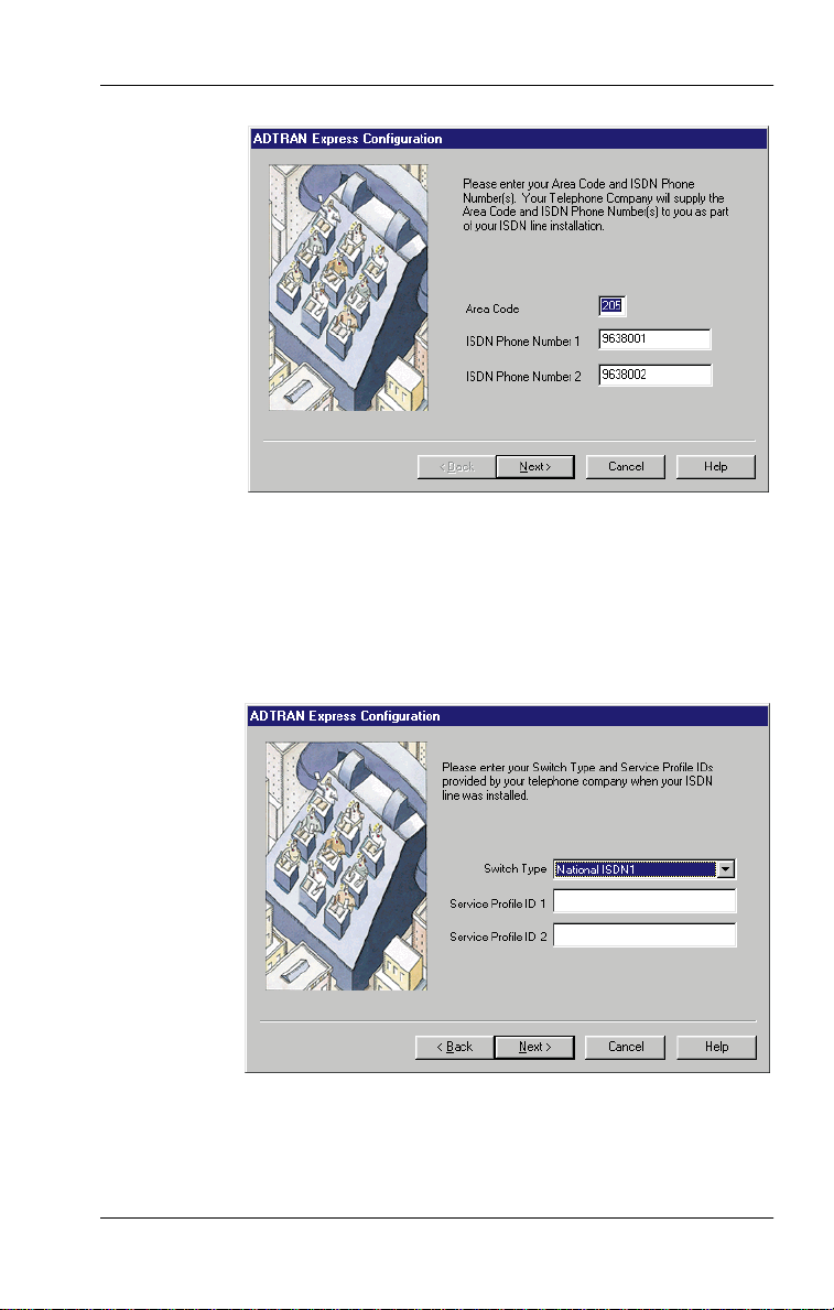
Chapter 3. Using the Express Configuration Program
Figure 3-8. Window for Entering ISDN Phone Numbers
Next
When you click
again, a new window opens (see Figure 3-9) for
entering the Switch Type, SPID 1, and SPID 2; however, you may not
need to enter this information as the Wizard uses advanced features to
auto-detect SPIDs and Switch Type.
Figure 3-9. Window for Entering SPID Numbers
61203153L2-20 Express 3000 User Manual 3-29
Page 70

Chapter 3. Using the Express Configuration Program
Automatically Running the Wizard on Startup
To instruct the ADTRAN Express Configuration program to automatically run the Wizard on startup, check the
(under
preferences
). To disable this feature, uncheck the checkbox.
Auto-Run Wizard
checkbox
LOCATING INFORMATION ABOUT THE PROGRAM
To find the version number and registration information about the
ADTRAN Express Configuration program, click on
panel of the GUI.
about
on the left
3-30 Express 3000 User Manual 61203153L2-20
Page 71

Chapter 4
Using
VT-100 Terminal
Emulation
You can configure the Express 3000 using any communications package that supports VT-100 terminal emulation. Ensure that the
Express 3000 is properly connected to your PC and that it is powered
on before you try to configure your unit.
Configuring the Exp ress 300 0 Using VT-100 Terminal Em ul ation
Step Action
1
Connect to a VT-100 terminal using a communications
package such as HyperTerminal.
2
At the prompt, enter the command
Enter
key.
(The Configuration screen displ ays; see
Figure 4-1.)
The AT command is not visible as you type since echo is
off by default. To enable echo, type
AT!V
and press the
.
ATE1
3
Enter the following information:
• Area Code
• ISDN phone number 1
• ISDN phone number 2
4
Enable Auto-Detect SPIDs/Switch and any other changes.
5
61203153L2-20 Express 3000 User Manual 4-1
Enter
Ctrl + X
to exit the menu.
Page 72

Chapter 4. Using VT-100 Terminal Emulation
Figure 4-1. VT 100 Terminal Configuration Menu
Accessing Terminal Menus
After establishing a VT-100 terminal emulation session, you can go to
a particular menu by pressing the hot key sequence for that menu (see
Table 4-1). If the hot keys don’t work, ensure that the co mmunications
package is configured to pass these control sequences through to the
Express 3000.
Table 4- 1. Menu Hot Keys
Menu Hot Keys
AODI (Ctrl + A)
CONFIG (Ctrl + C)
DIAL (Ctrl + D)
STATUS (Ctrl + V)
TEST (Ctrl + T)
The communications package must be configured to pass
these control sequenc es through to the Exp ress 3000.
4-2 Express 3000 User Manual 61203153L2-20
Page 73

Chapter 4. Using VT-100 Terminal Emulation
Exiting the Terminal Menus
To exit the terminal menus, type
Ctrl + X
.
Placing the Unit Back On-line
Ctrl + X
The
nected.
command also places the unit back on-line if a call is con-
Displaying the Status Buffer
Once you have accessed the terminal menus, type
to display the Express 3000
tains the Status Buffer.
Status
menu (see Figure 4-2) which con-
Ctrl + V
at any time
Figure 4-2. VT 100 Terminal Status Buffer Menu
61203153L2-20 Express 3000 User Manual 4-3
Page 74

Chapter 4. Using VT-100 Terminal Emulation
STATUS BUFFER MESSAGES
Status Buffer messages provide information about call progress, ISDN
link status, and error conditions (see Figure 4-2 on page 4-3). The Status Buffer contains only the last 20 status messages, with relevant status items, generated during unit operation. The most recent status
message appears as Status 1, with the remaining status messages appearing in descending order. Appendix B,
the Status Buffer messages and their descriptions
Status Buffer Messages
.
, lists
4-4 Express 3000 User Manual 61203153L2-20
Page 75

Chapter 5
The Express 3000 fully supports optional calling features such as
three- or six-way call conferencing, call forwarding, caller ID, call return, call holding, call transfer, call rejection, call waiting, and message waiting. To use these features, your touch-tone telephone must
connect to POTS 1 (see
page 2-11).
Optional Calling Features
Connecting Your Primary Te lephone
These features are available only if included in the ISDN
service to which you subscribe.
on
CALL CONFERENCING
Call Conferencing (also known as three-way calling) permits a conversation between three to six parties, each at different locations.
Instructions for Call Conferencing
Step Action
1
Establish a voice call.
2
Flash-hook (i.e., press the
key pad) to put the first party on hold and receive a second
dial tone.
3
Dial the second party.
4
Repeat steps 2 and 3 as necessary.
5
Flash-hook again to connect all callers.
61203153L2-20 Express 3000 User Manual 5-1
FLASH
button on the telephone
Page 76

Chapter 5. Optional Calling Features
CALL FORWARDING
If subscribed to, this service forwards incoming calls to a different
number. This action occurs after a certain number of rings or if the line
is in use (busy).
CALLER ID
Caller ID displays a caller’s name and phone number in a Caller ID
box.
CALL RETURN
With this feature, your telephone automatically dials the last incoming
call.
CALL REJECT
The Express 3000 provides two methods for rejecting incoming calls:
using a call reject list and rejecting anonymous calls. Both of these features are enabled and disabled from the
when you are working with User profiles.
Phone List
tab which opens
Call Rejection List
The Call Rejection List compares all incoming Speech and Audio calling party numbers to a user-created list of ten numbers that the user
wants rejected. If a match is found, the POTS port will not ring. Generally, the caller experiences a busy signal. To find out if calls have
been rejected, users must view the Status Buffer for rejection messages.
Anonymous Call Rejection
Sometimes callers block a party number so that you cannot see who is
calling in (i.e., an anonymous call). These numbers normally appear as
Private
5-2 Express 3000 User Manual 61203153L2-20
on a Caller ID unit. If the Anonymous Call Rejection feature is
Page 77

Chapter 5. Optional Calling Features
enabled, anonymous calls will not ring the POTS port. Generally, the
caller experiences a busy signal. To find out if calls have been rejected,
users must view the Status Buffer for rejection messages.
CALL WAITING
Call Waiting permits one voice call to be placed on hold while answering another voice call. To enable this option, follow the instructions
below.
Instructions for Enabling Call Waiting
Step Action
1
Flash-hook (i.e., press
to place the active call on hold and answer an incoming call.
2
Flash-hook as necessary between the two calls.
3
Hang up to terminate both calls.
FLASH
button on telephone keypad)
Controlling Call Waiting
Call waiting can be disabled and enabled on a
abled, you do not hear the call waiting tone.
Instructions for Enabling/Disabling the Call Waiting Tone
To... Do this...
Disable Using a touch-tone phone, press
Enable Hang up; the Express 3000 defaults to call waiting.
per-call
*70
.
basis. When dis-
61203153L2-20 Express 3000 User Manual 5-3
Page 78

Chapter 5. Optional Calling Features
MESSAGE WAITING INDICATOR
If your ISDN line provisioning includes a Message Waiting Indicator,
a stuttered dial tone is present on the POTS port when a message is unread. The stuttered dial tone is only present on the directory number
on which a Message Waiting Indicator has been provisioned. Once a
message is read, the stuttered dial tone stops.
When connecting to a National ISDN 1 switch, call
conferencing, message waiting, and call transferring are
assigned a unique feature identifier number. This number may
not be the same in all areas.
S-registers 90 through 93 (see Appendix A) contain the calling
feature identifier numbers used by the Express 3000. If these
numbers do not work in your area, contact your ISDN
provider.
PO TS PORTS DISTINCTIVE RINGS
You can set up the Express 3000 so that POTS ports 1 and 2 have distinctive rings that are easily recognized. S-register 19 controls this feature (see
S-Registers
on page A-2).
5-4 Express 3000 User Manual 61203153L2-20
Page 79

Chapter 6
Software upgrades provide you with new and improved features. The
Express 3000 flash-memory upgrades the software from a file
provided by ADTRAN. To check the software version currently
running, click on the
or view the
Use the Express Configuration program or a VT-100 terminal emulation program that supports the XMODEM or XMO DEM 1K proto cols
(such as HyperTerminal) to upgrade your software. This chapter provides instructions for upgrading software using the Express Configuration program and using HyperTerminal.
Upgrading Software
about
tab of the Express Configuration program
Status
menu via a VT-100 terminal emulation session.
If a terminal emulation package other than HyperTerminal is
selected, please see the instructions supplied with the package
to set up an XMODEM or XMODEM 1K connection.
UPGRADING FILES USING THE EXPRESS CONFIGURATION PROGRAM
Instructions for Upgrading Software Using the Express
Configuration Program
Step Action
1
Download the necessary upgrade files from the ADTRAN
web site (
2
Open the Express Configuration program. (If necessary,
see
instructions.)
61203153L2-20 Express 3000 User Manual 6-1
www.adtran.com
Opening the Program
).
on page 3-2 for detailed
Page 80
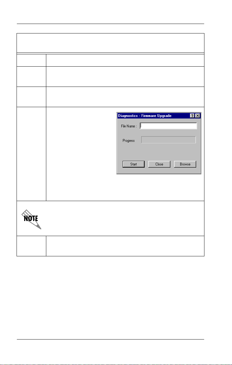
Chapter 6. Upgrading Software
Instructions for Upgrading Software Using the Express
Configuration Program
Step Action
3
Click on the Express Configuration program option
labeled
diagnostics
.
4
Enter the file name in the
File Name
field, or
the right file.
5
Click the
Start
button to
start the software
upgrade process.
When the software upgrade is complete, a
message displays indicating the status of the
software upgrade.
(If the software upgrade failed, see Troubleshooting on
page 8-1.)
During the software upgrade process, the
is no longer illuminated. Only the
TD LED
PWR/LINE LED
flashes during
the software upgrade process. Once the process is
complete, the Express 3000 automatically resets.
6
Close the Express Configuration program when you have
finished.
Browse
for
6-2 Express 3000 User Manual 61203153L2-20
Page 81

Chapter 6. Upgrading Software
UPGRADING SOFTWARE USING HYPERTERM INAL
Instructions for Upgrading Software Using HyperTerminal
Step Action
1
2
3
Download the necessary upgrade files from the
ADTRAN web site (
Connect to the Express 3000 via HyperTerminal:
a. Windows 95
Start
Windows 98
Start
>
b. When the
type in a connection name, select an icon, and click
OK
c. In the
field and select the COM port to which the
Express 3000 is connected; click
d. The
Change the
OK
Type
Programs> Accessories
>
>
Programs> Accessories
HyperTerminal
.
Connect To
COM port
.
AT!FLASHLOAD
www.adtran.com
>
> Communication
Connection Description
window, go to the
Properties
Bits per second
to initiate the firmware update.
window opens next.
field to
).
HyperTerminal
window opens,
Connect using
OK
.
57600
and click
The AT command is not visible since echo is off by default. (To enable echo, type
4
5
61203153L2-20 Express 3000 User Manual 6-3
Click the
Click
to the Express 3000.
Transfer
Browse
menu; then click
to locate the directory and file to download
ATE1
.)
Send File…
.
Page 82

Chapter 6. Upgrading Software
Instructions for Upgrading Software Using HyperTerminal
Step Action
6
7
Change the
Once the download is complete, exit HyperTerminal,
Protocol
1K Xmodem
to
and click
Send
.
saving the session if desired.
The software upgrade is now complete.
PWR/LINE, B1
If the
and
B2 LED
s are flashing, the software
upgrade failed. (In this case, see Troubleshooting on pa ge 8-1.)
6-4 Express 3000 User Manual 61203153L2-20
Page 83

Chapter 7
If you are using a PC running Windows 95/98, you can connect an
external or internal analog modem to the Express 3000 and access an
Internet Service Provider or host server that does not support ISDN.
When you check
commands sent to the COM port connected to the Express 3000 are
passed to the external analog modem; therefore, commands cannot be
sent to the Express 3000 when this mode is active. To resume
communication with the Express 3000, uncheck
This chapter describes the installation procedures for both external
and internal modems.
Installing an Analog Modem
Enable Modem
Windows NT 4.0 does not sup port this feature.
(on the Tray Tool Menu), all
Enable Modem
.
EXTERNAL ANALOG MODEM APPLICATION
To use an external analog modem with the Express 3000, you will
need the following items
Express 3000:
in addition to
the items provided with the
• External analog modem
• EIA-232 serial cable
• RJ-11 to RJ-11 telephone cable
• 16550 UART high-speed serial port (but only for data rates of
230.4 kbps)
Figure 7-1 illustrates the setup for an external analog modem connected to the Express 3000. This setup requires one PC COM port and supports DTE rates of up to 115.2 kbps.
61203153L2-20 Express 3000 User Manual 7-1
Page 84
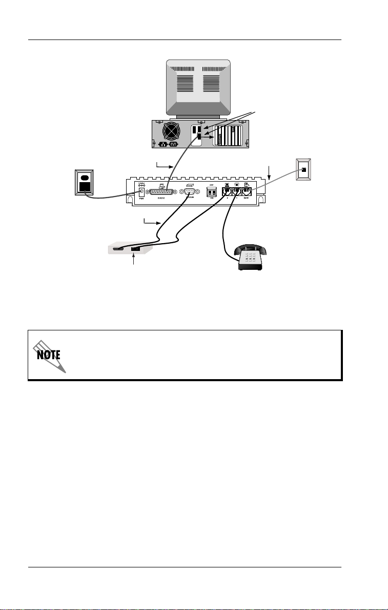
Chapter 7. Installing an Analog Modem
AC Outlet
PC
Rear View
EIA-232 Cable (1)
COM Ports
ISDN
Telephone Cable
ISDN
T elephone W all Jack
EIA-232 Cable (2)
Express 3000
Rear View
External Analog
Modem
Dial Line or
Line Jack
RJ-11 to RJ-11
Telephone Cables
Analog T elephone
Figure 7-1. External Analog Modem Application
EIA-232 cable 1 (pr ovided with th e Expr ess 3000) connects the
Express 3000 to the PC. EIA-232 cable 2 (provi ded by the user)
connects the external analog modem to the Express 3000.)
7-2 Express 3000 User Manual 61203153L2-20
Page 85

Chapter 7. Installing an Analog Modem
Connecting an External Analog Modem
To connect an external analog modem to the Express 3000 use the following procedure:
Instructions for Connecting an External Analog Modem
Step Action
1
2
3
Ensure that the Express 3000 is connected to the PC
via the provided EIA-232 cable, and that the PC is
turned on.
Ensure that the modem power is
plugged in).
Connect one end of the second EIA-232 serial cable to
the external analog modem and the other end to the
Express 3000 port labeled
modem is positioned above this port).
off
MODEM
(i.e., it’s not
(an illustration of a
Incoming calls must use ISDN phone number 2 for
external analog applications.
4
5
Connect one end of the RJ-11 to RJ-11 telephone cable
POTS port 2
to
telephone above a modem is positioned above this port)
and the other end to the
external analog modem. (See the external anal og
modem’s documentation to determine which modem
jack is the
Power on the external analog modem (i.e., plug it in).
on the Express 3000 (an illustration of a
Dial Line
or
Dial Line
Line
jack.)
or
Line
jack on the
(The external analog modem is now connected to the
Express 3000.)
If you are connecting an external analog modem that has already been
in use by a PC running Windows 95/98, you are ready to use the external analog modem. Enable the exter nal analog modem usi ng either
61203153L2-20 Express 3000 User Manual 7-3
Page 86

Chapter 7. Installing an Analog Modem
the Express Configuration program (Tray Tool Menu) or by using a
VT-100 terminal emulation package (such as HyperTerminal).
If you are connecting an external analog modem that has not been
used by a PC running Windows 95/98, you must configure it before
you can use it (see
Configuring the External Analog Modem
on page 7-4).
Configuring the External Analog Modem
To configure the external analog modem, set up the communications
software so it uses the same serial COM port to which the
Express 3000 is connected.
To install and use an external modem that does not support
230.4 kbps, set
ON (down)
230.4 kbps operation for ISDN connections, set
OFF (up)
When using an external analog modem that does not support
230.4 kbps with applications that support Express 3000 operation at
230.4 kbps, attach the Express 3000 to the high-speed 16650 UART
COM port and connect the external analog modem to a separate COM
port. This setup allows the Express 3000 to operate at 230.4 kbps and
the external modem to operate at the reduced speed.
DIP Switch 1
, thus limiting the DTE speed to 115.2 kbps. To r e-enable the
position.
on the back panel of the Express 3000 to
DIP Switch 1
to the
Setting the Carrier Detect Signal
Before enabling the modem using the Express Configuration program, set the
(track CD signal). Use the AT command
commands into the modem, open a VT-100 terminal emulation session and enter the following (
ter
key to insert a carriage return):
7-4 Express 3000 User Manual 61203153L2-20
Carrier Detect
(CD) signal from the modem to
AT&C1
indicates you should press the
<cr>
to do this. To enter AT
Normal
En-
Page 87

Chapter 7. Installing an Analog Modem
Command Function
AT_L1 <cr>
AT <cr>
ATI <cr>
AT&C1 <cr>
AT&W <cr>
AT_L0 <cr>
Enables external analog modem.
OK response (sets modem baud rate).
Identifies the modem (verifies modem connected).
Sets CD to normal.
Saves settings.
Disables external analog modem.
CONTROLLING AN EXTERNAL ANALOG MODEM
You can enable and disable (control) an external modem w ith the Windows 95/98 Tray Tool Men u (see
or with VT-100 terminal emulation (discussed here). When the
Express 3 000 enables the external modem port, the external analog
modem RTS and CTS lines directly switch over to the PC COM port.
This switching process allows the external analog modem to provide
flow control as normal. Once the modem is enabled, all further COM
activity transmits to the external analog modem. When the modem is
disabled, the ISDN terminal adapter within the Express 3000 processes all further COM port activity.
Launching the Tray Tool
on page 3-3)
Controlling the Modem via T erminal Emulation
Another method of controlling an external analog modem is using a
VT-100 terminal emulation package such as HyperTerminal. First, determine if the external analog modem is properly connected to the
Express 3000 by typing the AT command
key. If properly connected, the Express 3000 responds with the mes-
MODEM FOUND
sage
connected, the Express 3000 responds with the message
FOUND
61203153L2-20 Express 3000 User Manual 7-5
.
The
analog modem itself. An
sent while the external analog modem is enabled.
. If the external analog modem is not properly
command is directed to the Express 3000, not the
AT!Z
ERROR
and pressing the
AT!Z
NO MODEM
occurs if the command is
Enter
Page 88

Chapter 7. Installing an Analog Modem
Using VT-100 Terminal Emulation to Enable/Disable the Modem
To do this... Enter this AT Command
Enable modem
Disable modem
AT_L1
AT_L0
and press the
and press the
Enter
Enter
key
key
When carrier detect (CD) is active (i.e., a call is connected) on the external analog modem, the Express 3000 will not switch control from
the modem port when you attempt to disable it. The call must be
hung-up (disconnected) to deactivate CD, before you can switch control from the modem port and disable it.
INTERNAL ANALOG MODEM APPLICATION
The following items are necessary to connect an internal analog modem to the Express 3000:
• Internal analog modem
• RJ-11 to RJ-11 telephone cable
When using an internal analog modem with the Express 3000, two
COM ports are assigned on the PC and configured independently. See
the manufacturer's documentation for internal analog modem co nfiguration.
Figure 7-2 on page 7-7 illustrates the connections for installing an internal modem to the Express 3000.
7-6 Express 3000 User Manual 61203153L2-20
Page 89

Chapter 7. Installing an Analog Modem
ISDN Cable
Figure 7-2. Internal Analog Modem Connections
Connecting an Internal Analog Modem
To connect an internal analo g modem to th e Express 3000, use the following procedure:
Instructions for Connecting an Internal Analog Modem
Step Action
1
Ensure that the Express 3000 is connected to the PC.
2
Connect one end of the RJ-11 to RJ-11 telephone cable
to the telephone jack labeled
3
Connect the other end of the RJ-11 to RJ-11 telephone
cable to the
Dial Line
or
2
on the Express 3000.
Line
jack on the internal analog
modem.
See the internal analog modem documentation to determine
which jack on the internal analog modem is the
Line
jack.
61203153L2-20 Express 3000 User Manual 7-7
Dial Line
or
Page 90

Chapter 7. Installing an Analog Modem
7-8 Express 3000 User Manual 61203153L2-20
Page 91

Chapter 8
Troubleshooting
TROUBLESHOOTING GUIDELINES
This section provides troubleshooting techniques to resolve problems
that may be encountered while operating the Express 3000. If problems persist, contact ADTRAN technical support for assistance (see
the inside back cover of this manual for more information). Topics
covered in this chapter are listed below:
PWR / LINE LED is off.
•
PWR / LINE LED flashes, and 1 and 2 LEDs are off.
•
PWR / LINE LED, and 1 and 2 LEDs flash green.
•
Dial-up connection problems.
•
Auto-detect Switch SPIDs remains at Link Down.
•
Express 3000 not detected.
•
External analog modem not detected.
•
Difficulty with 230.4 kbps operation.
•
Dial-up networking difficulty.
•
See page 8-2
See page 8-2
See page 8-2
See page 8-4
See page 8-5
See page 8-6
See page 8-6
See page 8-7
See page 8-7
61203153L2-20 Express 3000 User Manual 8-1
Page 92

Chapter 8. Troubleshooting
PWR / LINE LED is off.
This indicates a problem with the power to the unit.
1. Verify that the power cord is connected to the Express 3000, and
that it is plugged into a working 120 volt AC electrical outlet.
PWR / LINE
LED flashes, and 1 and 2
LEDs are off.
This indicates a problem with the physical connection of the ISDN
line between the Express 3000 and the local telephone company.
1. Verify that the large end of the ISDN telephone cable (provided
with the Express 3000) is connected to the ISDN connector on
the rear panel of the Express 3000.
2. Verify that the small end of the same ISDN telephone cable is
connected to the ISDN telephone wall jack that is installed with
a Basic Rate ISDN.
3. If steps 1 and 2 do not solve the problem, contact your local telephone service provider.
PWR / LINE LED, and 1 and 2 LEDs flash
green.
This indicates a configuration problem.
1. Verify that the following information has been correctly entered:
• Switch Type
• Service Profile Identifiers (SPIDs)
• ISDN Phone Numbers
8-2 Express 3000 User Manual 61203153L2-20
Page 93

Chapter 8. Troubleshooting
PWR / LINE LED, and 1 and 2 LEDs flash
green. (Continued)
a. To verify this information, click
nostics
click
invoke the VT-100 menu system, issue the AT comman d
AT!V
minal.)
b. You can also use
ences
Type. In the ADTRAN Express Configuration program,
click
the
screen of the VT-100 menu system. (To invoke the VT-100
menu system, issue the AT command
emulation package such as HyperTerminal.)
c. If all configuration information is correct, and the unit is
properly connected,
link status is good and calls still cannot be placed, refer to
page 8-4.
2. Look for the following with the COM port setup:
• IRQ conflicts
• Wrong DTE speed
on the ADTRAN Express Configuration wi ndow, or
Configuration Screen
from a terminal emulation package such as HyperTer-
Auto-Detect Express 3000
) to automatically detect the SPIDs and the Switch
wizard
on the Express Configuration window or, use
Auto-Detect SPIDs / Switch
Link Status
PWR /LINE
If the
sequentially, after a software upgrade, a problem occurred
during the download. Restart the download using the
instructions in Chapter 6. If the download fails a second time,
contact ADTRAN technical support (see inside back cover).
LED, and 1 and 2 LEDs flash green,
Register Dump
in the VT-100 menu system. To
(under
option in the
AT!V
indicates
Configuration
from a terminal
Link Up
under
prefer-
. If the
diag-
61203153L2-20 Express 3000 User Manual 8-3
Page 94

Chapter 8. Troubleshooting
Dial-up connection problems.
A variety of causes may result in dial-up connection problems.
1. Status Buffer messages r eturned fr om the ISDN ne twork and the
Express 3000 can help diagnose many dial-up connection problems.
a. Access these messages by clicking
Remote) on the
diagnostics
Status Buffer
(Local or
option on the ADTRAN
Express Configuration window.
b. Alternatively, you can access the
key sequence
Ctrl+V
in the VT-100 menu system. (To invoke
the VT-100 menu system, issue the AT command
Status Buffer
by using the
from
AT!V
a terminal emulation package such as HyperTerminal.)
2. Ensure the following to verify the correct protocol is selected:
• PPP or V.120 generally for Internet applications
• V.120 or Multilink PPP f or work-at-home
8-4 Express 3000 User Manual 61203153L2-20
Page 95

Chapter 8. Troubleshooting
Auto-detect Switch SPIDs remains at Link
Down.
Link Down
A
indicates a problem with the ISDN line provided from the telephone
company. Usually, the ISDN physical layer device ha s been unable
to synchronize to the network.
1. Verify that the Express 3000 is powered on.
2. Verify that the provided ISDN telephone cable is correctly
installed between the Express 3000 and the ISDN wall jack.
a. If the wall jack does not have ISDN installed on the two
b. Call the local telephone company and have them check the
condition persisting for longer than five minutes
middle pins (tip and ring), the Express 3000 will never synchronize to the telephone switching equipment.
ISDN line for correct operation.
61203153L2-20 Express 3000 User Manual 8-5
Page 96

Chapter 8. Troubleshooting
Express 3000 not detected.
The Express 3000 may not be detected for several reasons.
1. Verify the following:
a. The Express 3000 is powered on.
b. No other applications are running that could be using the
COM port to which the Express 3000 is attached.
A Windows application does not have to be active to tie up a
COM port. Be sure to check the Windows 95/98 Taskbar for
any suspended applications (such as HyperTerminal) that
may be using the COM port. If any applications are minimized, they must be closed
Express Configuration program.
before
starting the ADTRAN
2. If you are operating at 230.4 kbps, move
Off
(up)
.
3. Confirm that the computer has a 16650 UART.
DIP switch 1
to
External analog modem not detected.
Verify the following:
1. The external analog modem is powered on.
2. The external analog modem is properly installed and configured
for use with the Express Configuration program.
8-6 Express 3000 User Manual 61203153L2-20
Page 97

Chapter 8. Troubleshooting
Difficulty with 230.4 kbps operation.
If the Express 3000 does not work when the DTE rate is set (inside
Windows) to 230.4 kbps, verify the following:
DIP switch 1
1.
2. A high-speed serial card with a 16650 UART is being used, and
the software drivers to support the extended baud rate tables are
installed.
on the back of the Express 3000 is set to
Off (up)
.
Dial-up networking difficulty.
1. If Windows 95/98 Dial-Up Networking cannot talk to the
Express 3000, check the modem configuration for the
Express 3000 and ensure the bit rate for the DTE is set correctly.
2. If the PC is not equipped with a 16650 UART, then the fastest
DTE operation speed is 115.2 kbps; ensure the speed is not
higher than the PC and modem can support.
61203153L2-20 Express 3000 User Manual 8-7
Page 98

Chapter 8. Troubleshooting
8-8 Express 3000 User Manual 61203153L2-20
Page 99

Appendix A
AT Commands and
S-Registers
AT COMMANDS
AT commands issue directions to the Express 3000 via a VT-100 terminal emulation session. The DTE serial port accepts AT commands only
when no calls are established; i.e., the carrier detect (CD) signal is inactive. When a call is established, the CD signal is active and the port
is used for data. The port cannot be used simultaneously to issue AT
commands and transmit and receive data. After entering command
mode (CD inactive), you can transmit AT commands to the Express
3000 to configure most options, dial re mote Express 3000s, and initiate
tests to check both the Express 3000 and the network connections.
Escape Sequence and Guard Time Delay
To exit data mode (CD active) and enter command mode, the DTE serial port must transmit a proper escape sequence to the Express 3000.
A specified time delay must occur between the last data character and
the first escape sequence character. This delay is the guard time delay.
You can change the guard time by writing a value to the S12 register.
For a valid escape sequence to occur, the DTE must transmit the escape code character
each character less than the guard time.
three
times in succession with the delay between
The default escape sequence is
is one second.
61203153L2-20 Express 3000 User Manual A-1
and the default guard time delay
+++
Page 100

Appendix A. AT Commands and S-Registers
Entering Text into the Command Line
All command lines must begin with the AT character set in either all
uppercase or all lowercase letters. After the AT attention code, the
command line may contain a single command or a series of commands; however, AT commands
separate line and followed by
mands, you may separate the individual commands with spaces for
readability. The maximum length for a command line is 40 characters.
After receiving a terminating character, the Express 3000 executes
each command line. The default terminating character is a carriage return (ASCII 013), but it can be changed by writing a differen t value to
register S3. Before transmitting the terminating character, you can edit
the command line by using the backspace character (ASCII 008) to
erase errors so the proper commands can be entered.
Enter
and
_L1
. When entering a series of com-
must be entered on a
_L0
To return an active call to the on-line state, enter
ATO
.
Entering AT Commands
To enter an AT command, type
press the
example,
Enter
key (the AT Commands list begins on page A-4). For
ATI1
returns the software version of the Express 3000 unit.
followed by the command; then,
AT
S-REGISTERS
You can change or view the Express 3000 configuration using the
S-registers (the S-registers list begins on page A-9).
Reading S-Registers
To read an S-register, type AT, the S-register number, a question mark,
and then press the
Auto Answer options.
A-2 Express 3000 User Manual 61203153L2-20
Enter
key. For example,
ATS0?
lets you view the
 Loading...