

Page 1
®
Total Access 1500 Dual Line Interface Unit (LIU)
Installation and Maintenance Practice
CONTENTS
1. General .................................................................... 1
2. Installation............................................................... 2
3. Provisioning ............................................................ 4
4. Alarms ................................................................... 10
5. Tests ...................................................................... 10
6. Maintenance .......................................................... 10
7. Specifications ........................................................ 11
8. Warranty and Customer Service ........................... 11
FIGURES
Figure 1. Dual LIU Front Panel .................................. 1
Figure 2. DIP Switches................................................ 4
Figure 3. Dual LIU Menu Tree ................................... 6
TABL ES
Table 1. Compliance Codes ........................................ 2
Table 2. Front Panel LEDs.......................................... 3
Table 3. Dual LIU Switch Settings ............................. 5
Table 4. Dual LIU Specifications.............................. 11
Section 61180009L1-5D
Issue 4, May 2006
CLEI Code: VAL2HF0A_ _
1. GENERAL
This practice is an installation and maintenance guide
for the ADTRAN
®
Total Access 1500® Dual Line
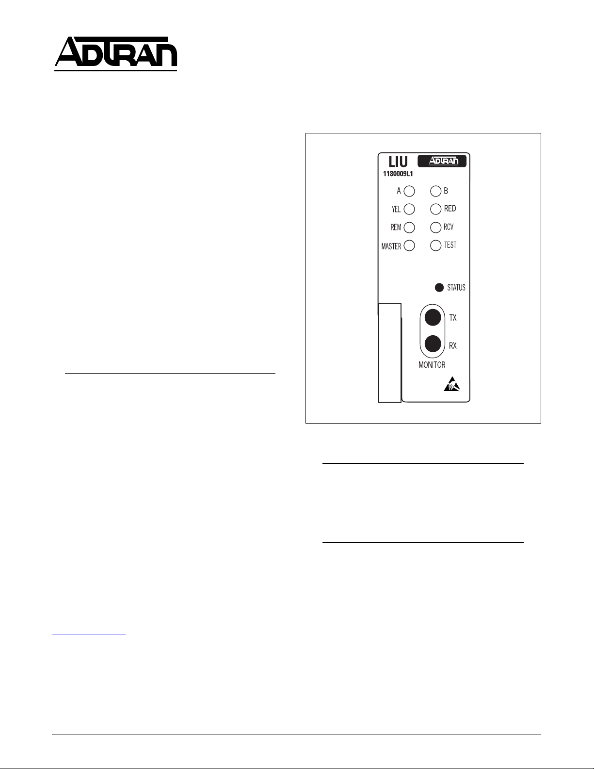
Interface Unit (LIU) Common Module. Figure 1 shows
the Dual LIU (P/N 1180009L1) front panel.
Revision History
This is the fourth issue of this practice. This issue
reflects updates to the Total Access 1500 System
Software Release 3.0, Dual LIU software T07D, and
incorporates the addition of new features including:
• Changed
CLK OOS Alarm in Alarms menu to
Disable as factory default
• Incorporation of automatic mapping for 2B+D
ISDN when in Dual T1 mode
• Removed signaling bits from 4-wire TO
A full list of features is detailed in Total Access 1500
System Release 3.0 Release Notes available at
www.adtran.com
.
Figure 1. Dual LIU Front Panel
NOTE
This release of the LIU software is designed to
operate with System Controller Unit (SCU)
software release V08 or later to support these
feature enhancements.
Description
The Dual LIU is a common module for the Total Access
1500 chassis (P/N 1180001L1) or the Total Access
1500 19-inch chassis (P/N 1180019L1).
The Dual LIU connects the chassis to a T1 line at the
DSX-1 or DS1 level. All data formatting and line
encoding as well as backplane timing and control are
performed by the Dual LIU.
61180009L1-5D 1
Trademarks: Any brand names and product names included in this document are
trademarks, registered trademarks, or trade names of their respective holders.
Page 2

Features
The basic features of the Dual LIU include the
following:
2. INSTALLATION
• Terminates up to 2 T1 lines providing DSX-1 or
DS1 interface to the network
• Supports up to 48 DS0s
• SF or ESF data framing formats
• AMI or B8ZS line code formats
• Local and remote loopbacks
• Front panel bantam jacks for monitoring T1s
• Local, loop, or external timing modes
• Supports ANSI T1.403 in-band payload and line
loopback
Compliance
Table 1 shows the compliance codes for the Dual LIU.
The Dual LIU is NRTL listed to the applicable UL
Listing.
The Total Access 1500 chassis frame ground terminal
must be connected to an earth ground to ensure that the
front panel of the Dual LIU is properly grounded via the
backplane connector.
Table 1. Compliance Codes
Code Input Output
Power Code (PC) F C
Telecommunication Code (TC) – X
C A U T I O N !
SUBJECT TO ELECTROSTATIC DAMAGE
OR DECREASE IN RELIABILITY.
HANDLING PRECAUTIONS REQUIRED.
After unpacking the Dual LIU, inspect it for damage. If
damage has occurred file a claim with the carrier, then
contact ADTRAN Customer Service. Refer to the
Warranty and Customer Service section for further
information. If possible, keep the original shipping
container for returning the Dual LIU for repair or for
verification of shipping damage.
Shipping Contents
The contents include the following items:
•Dual LIU
• Dual LIU Installation and Maintenance Practice
CAUTION
Electronic modules can be damaged by ESD.
When handling modules, wear an antistatic
discharge wrist strap to prevent damage to
electronic components. Place modules in
antistatic packing material when transporting
or storing. When working on modules, always
place them on an approved antistatic mat that is
electrically grounded.
Installation Code (IC) A –
This device complies with Part 15 of the FCC rules.
Operation is subject to the following two conditions:
1. This device cannot cause harmful interference.
2. This device must accept any interference received,
including interference that can cause undesired
operation.
Changes or modifications not expressly approved by
ADTRAN could void the user’s authority to operate this
equipment.
Instructions for Installing the Module
The Dual LIU plugs directly into the Total Access 1500
channel bank. No installation wiring is required.
The Dual LIU should be installed in the Total Access
1500 channel bank in the slot labeled
LIU-A or LIU-B.
Refer to Provisioning on page 4 prior to card insertion.
CAUTION
This release of the LIU software is designed to
operate with SCU software release V08 or later
to support feature enhancements. SCU
software can be found at www.adtran.com
under the Service/Support page.
To install the Dual LIU, perform the following steps:
1. If present, remove the LIU Blank (P/N 1180010L1)
from the appropriate LIU common module slot of
the Total Access 1500 chassis.
2 Issue 4, May 2006 61180009L1-5D
Page 3

2. Hold the Dual LIU by the front panel while
supporting the bottom edge.
3. Align the Dual LIU card edges to the guide
grooved for the slot designated
LIU-A.
4. Insert the Dual LIU until the edge connector seats
firmly into the backplane.
5. Push the ejector in place to ensure the Dual LIU is
fully seated.
NOTE
An additional
LIU-B slot is also provided for
optional redundancy. For dual operation, only
Dual LIUs of the same software revision
should be installed.
Table 2. Front Panel LEDs
Label Condition Description
When the Dual LIU first powers up it performs the
power up self-tests, which check the DRAM and
checksum. Once the power up self-test is complete, the
status LEDs will reflect the true state of the hardware.
Front Panel LEDs
The front panel LEDs provide status and alarm information. See Table 2 for LED descriptions.
Front Panel Pushbutton
A pushbutton switch labeled
STATUS is accessible
from the front panel to aid in test and troubleshooting.
MONITOR TX and RX bantam jacks are provided
The
for T1 access.
NOTE
TX = Transmit (Out) and RX = Receive (In)
A
B
RED
YEL
RCV
REM
TEST
MASTER
Red
Yellow
Green
Flashing
Off
Red
Yellow
Green
Flashing
Off
Red ON = Monitored T1 in Red Alarm
Yellow ON = Monitored T1 in Yellow Alarm
Red ON = Monitored T1 bipolar or logic error detected
Green
Off
Yellow ON = Test Mode Active
Green
ON = T1-A in Red Alarm
ON = T1-A in Yellow Alarm
ON = T1-A Active
FLASHING = T1-A in Test
OFF = In Monitor Mode
ON = T1-B in Red Alarm
ON = T1-B in Yellow Alarm
ON = T1-B Active
FLASHING = T1-B in Test
OFF = In Monitor Mode
ON = Remotely Provisioned (Craft or Network)
OFF = Locally Provisioned (DIP Switches)
ON = Online Unit
Flashing
STATUS
61180009L1-5D Issue 4, May 2006 3
Switch Momentary activation cycles through the T1s for monitoring purposes. Activating
FLASHING = Provisioning in progress. Failover not possible.
the switch for two or more seconds will cause provisioning to toggle between local
and remote.
Page 4
3. PROVISIONING
All options on the Dual LIU are provisionable either
manually, using internal DIP switches, or electronically
using the SCU
ADMIN port.
Windows HyperTerminal
Windows HyperTerminal can be used as a VT100
terminal emulation program. Refer to the Help section
of HyperTerminal for additional information.
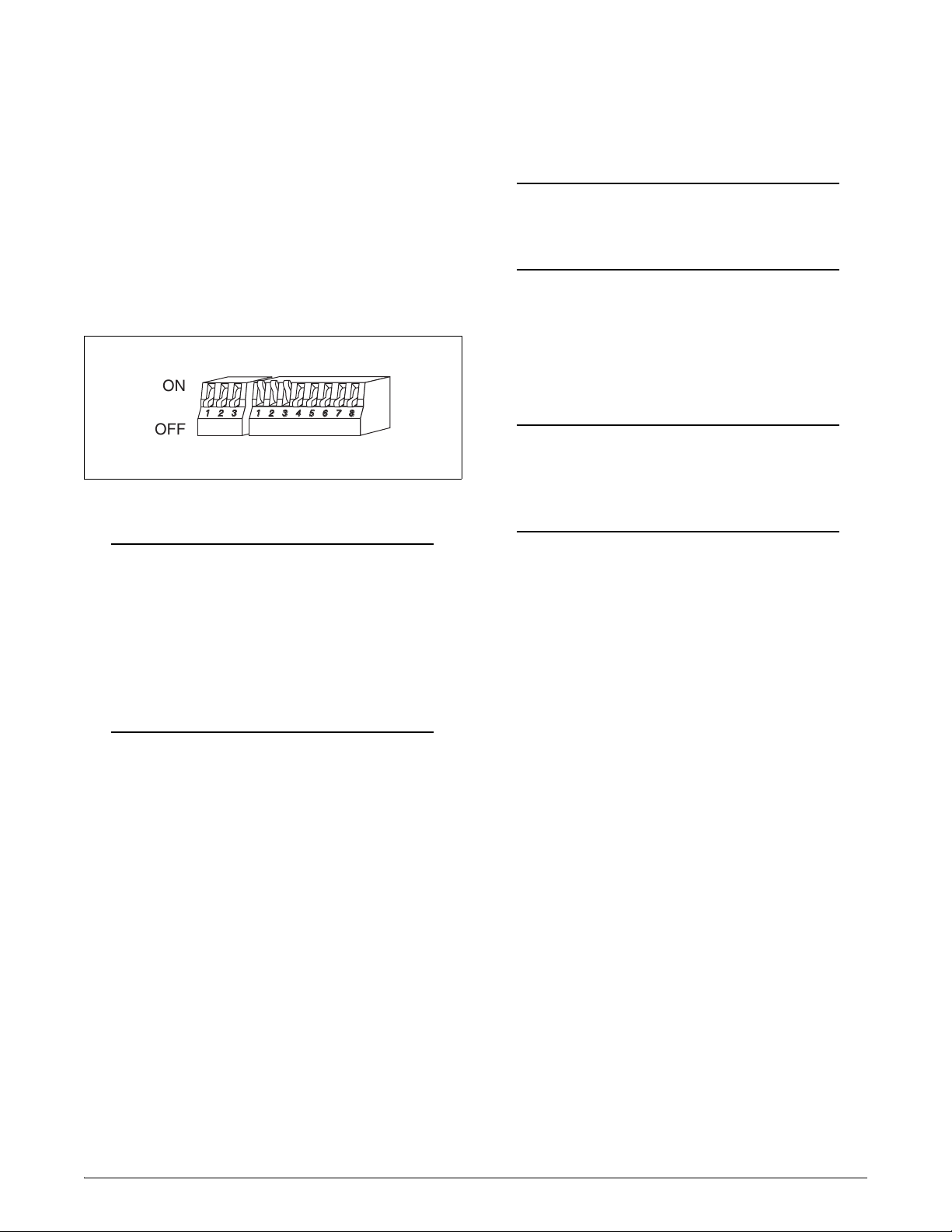
Manual Provisioning
The DIP switches SW1 and SW2 provide the Total
Access 1500 with the necessary option settings for
DSX/DS1 modes of operation. Figure 2 shows the
orientation of the DIP switches. Ta bl e 3 on page 5
shows the available DIP switch settings.
ON
123
OFF
12345678
Figure 2. DIP Switches
NOTE
DIP switch settings can be used for the initial
turn up of the system, and will automatically
assign time slots to physical slots, depending
on the setting selected. If any setting is
changed via the VT100 interface, the
REM
LED on the front panel will light indicating
that the settings have changed.
Electronic Provisioning
The craft ports on the Total Access 1500 SCU are used
to change default options and obtain access module
status through menu screens. To access the menu
screens, connect a VT100 terminal or computer running
a terminal emulation program to the SCU front panel
ADMIN port using a standard male RS-232, DB-9 cable.
ADMIN port settings are as follows:
• 9600 baud
• No parity
• 8 data bits
• 1 stop bit
• No flow control
NOTE
To ensure proper display background, select
VT100 terminal emulation under Settings.
Password and User ID
Password protection is a function of the SCU and is
factory disabled. If password authentication is enabled,
then the SCU will display the Logon screen. A valid
User Name and Password are required to access menus.
NOTE
The factory default User Name is “user”, and
the default Password is “password”. The User
Name and Password are not case sensitive.
Menu Navigation
To traverse through the menus, select the desired entry
and press
the
Enter. To work backward in the menu press
Esc key.
The menu tree in Figure 3 on page 6 illustrates the path
to every provisioning, performance, and test access
point in the Total Access 1500 Dual LIU menu.
Menus
The following subsections describe the Dual LIU menu
screens.
Main Menu
The LIU main menu provides access to the Dual LIU for
various functions such as viewing configuration, provisioning, viewing the current status of the module, setup
of alarms, testing, and performance monitoring.
Configuration Screen
The LIU Configuration screen is a read-only display. It
provides configuration data pertaining to the Dual LIU
and cannot be changed. Information such as unit name,
CLEI code, part number, product revision, and software
revision are displayed. Items such as Software Revision
will reflect new software revisions as upgrades are
performed.
4 Issue 4, May 2006 61180009L1-5D
Page 5

Table 3. Dual LIU Switch Settings
Switch Function Description
SW1 DSX-1 Line Build Out
and DS1 Attenuation
SW2-1
OFF
ON
SW2-2
OFF
ON
Line Code Format
AMI
B8ZS*
Framing Format
SF
ESF*
Selects the Line Build Out in feet; Attenuation in Decibels (dB)
Distance SW1-1 SW1-2 SW1-3
0-133 (Feet)/0 dB* OFF OFF OFF
133-266 OFF OFF ON
266-399 OFF ON OFF
399-533 OFF ON ON
533-655 ON OFF OFF
–7.5 dB ON OFF ON
–15 dB ON ON OFF
–22.5 dB ON ON ON
Enables Bipolar Eight Zero Substitution (B8ZS), which allows for Clear Channel
operation for the T1 carrier system, or Alternate Mark Inversion (AMI). This
option must be configured identically with all other T1 network equipment on this
circuit.
Enables either Extended Superframe Format (ESF) or Superframe Format (SF).
This option must be configured identically with all other T1 network equipment on
this circuit.
SW2-3
SW2-4
SW2-5
SW2-6
SW2-7
* Denotes factory default settings
Note: SW1-1 through SW2-4 set up both T1s identically.
Timing Mode Determines a clock source for the Total Access 1500 channel bank.
Function SW2-3 SW2-4
Local clock – provided by local LIU OFF OFF
Loop A clock – uses recovered clock from T1 bit
stream*
External clock input ON OFF
Terminal Mode Select the appropriate Terminal Type and counting mode for the Total Access 1500
system.
Terminal Mode Counting SW2-5 SW2-6 SW2-7
D4* D4 OFF OFF OFF
D4 D1D OFF OFF ON
Dual D4 D4 OFF ON OFF
OFF ON
61180009L1-5D Issue 4, May 2006 5
Page 6

1. Configuration
Unit Name
CLEI Code
Part Number
Product Revision
Software Revision
2. Provisioning
1. Bank Provisioning
2. DS1 Circuit Provisioning
1. Bank Mode
2. Counting Sequence
3. Inband Loopback
1. Circuit Select
2. Operation State
3. Line Buildout
1. Single T1
2. Dual T1
3. Manual Map
1. D4
2. D1D
1. Enable
2. Disable
1. Circuit A
2. Circuit B
1. Enable
2. Disable
1. 0-133 ft.
2. 133-266 ft.
3. 266-399 ft.
4. 399-533 ft.
5. 533-655 ft.
6. 0 dB
7. -7.5 dB
8. -15 dB
9. -22.5 dB
4. Line Code
5. Framing
1. Clock Mode
3. Timing Provisioning
2. Primary Timing Source
3. Secondary Timing Source
4. Time Slot Assignment
A
1. Assign by Card Slot
2. Assign T1 A
3. Assign T1 B
1. B8ZS
2. AMI
1. ESF
2. SF
1. Non-revertive
2. Revertive
1. Local
2. Loop A
3. Loop B
4. CLK
Figure 3. Dual LIU Menu Tree
6 Issue 4, May 2006 61180009L1-5D
Page 7

A
3. Status
4. Alarms
5. Test
Circuit A
Circuit B
Timing Source
Bank Mode
1. CLK OOS Alarm
1. T1 Loopbacks
2. T1 Monitor Select
Line Buildout
LIne Code
Framing
Inband Loopback
Loopback
Loop Status
Primary
Secondary
Current
1. Enable
2. Disable
1. T1-A
2. T1-B
1. None
2. T1 A
3. T1 B
1. None
2. Local
3. Line & Local
4. Payload
5. Line
6. Remote Inband
7. Remote Line*
8. Remote Payload*
6. Performance Monitoring
* Not available in SF Framing.
4. LIU Reset
1. Daily
2. Far-End Daily
3. Qtr-Hour
4. Far-End Qtr-Hour
5. Daily Threshold
6. FE Daily Threshold
7. Qtr-Hour Threshold
8. FE Qtr-Hour Threshold
9. Reset Performance Registers
10. Restore Factory Default Thresholds
11. Enable all LIU Threshold Alarms
12. Disable all LIU Threshold Alarms
13. Select T1
1. T1-A
2. T1-B
Figure 3. Dual LIU Menu Tree (continued)
61180009L1-5D Issue 4, May 2006 7
Page 8

Provisioning Menu
The Dual LIU Provisioning menu is a top-level provisioning screen which contains several other provisioning categories that allow users to make provisioning
changes to the Dual LIU.
The provisioning categories are listed below with all
respective submenus listed under each category.
3. Line Buildout: This option is used to select the
line length or the attenuation loss of the selected
T1. Option include the following:
• 0-133 feet
• 133-266 feet
• 266-399 feet
Bank Provisioning
The Bank Provisioning menu items are used to set
general channel bank provisioning settings. Options
include the following:
1. Bank Mode: This option is used to select the bank
mode for the Total Access 1500. Options include
the following:
•Single T1
•Dual T1
•Manual Map
NOTE
If Manual Map is selected, time slots must be
assigned using the
Time Slot Assignment
option from the LIU Provisioning menu.
2. Counting Sequence: This option is used to select
the counting sequence of the selected T1. The
options include the following
•D4
•D1D
3. In-band Loopback: This option is used to enable
or disable ANSI T1.403 in-band loopbacks.
• 399-533 feet
• 533 - 655 feet
•0 dB
• –7.5 dB
•–15 dB
• –22.5 dB
4. Line Code: This option is used to select the line
coding type. Options include the following:
• B8ZS: This option is used to enable Bipolar Eight
Zero Substitution (B8ZS), which allows for Clear
Channel operation for the T1 carrier system. This
option must be configured identically with all
other T1 network equipment on this circuit.
• AMI: This option is used to enable Alternate
Mark Inversion (AMI). This option must be
configured identically with all other T1 network
equipment on this circuit.
5. Framing: This option is used to select the framing
format for the selected T1. This setting must be
configured identically with all other T1 network
equipment on this circuit. Options include the
following:
• ESF: This option is used to enable Extended
Superframe Format.
DS1 Circuit Provisioning
The DS1 Circuit Provisioning menu items are used to
• SF: This option is used to enable Superframe
Format.
provision the DS1 circuit. Options include the
following:
Timing Provisioning
The Timing Provisioning menu items are used to
1. Circuit Select: This option is used to select the
circuit to be provisioned. The options include the
establish the clock mode and primary and secondary
timing source. Options include the following:
following:
1. Clock Mode: Options include Non-revertive or
• Circuit A
• Circuit B
2. Operation State: This option is used to enable or
disable the operation state of circuits A and B.
8 Issue 4, May 2006 61180009L1-5D
Revertive clock mode. This decision should be
based on whether a primary and secondary timing
source are available. In the event that the primary
timing source is lost, the Dual LIU will automatically switch to the secondary timing source.
Page 9

• Revertive: This option allows the unit to revert to
the primary timing source if and when it becomes
available.
• Non-revertive: This option allows the unit to
remain on the secondary timing source. If Nonrevertive is chosen and the secondary timing
source becomes active due to a primary timing
source failure and the secondary source fails, the
unit will switch to the primary timing source if it
has become available.
2. Primary Timing Source: This option is used to
select the primary timing source for the T1s.
Options include the following:
•Local
• Loop A
• Loop B
•CLK
3. Secondary Timing Source: This option is used to
select the secondary timing source for the T1s.
Options include the following:
•Local
• Loop A
• Loop B
•CLK
This timing source will become the current timing
source if the primary timing source is lost. If both
timing sources are lost, the timing reverts to local.
As timing sources are regained, the current timing
source reverts to the primary or secondary timing
source as they become available.
Time Slot Assignment
Used to assign time slots when the bank is in manual
map mode. This option allows time slots to be assigned
by T1-A, T1-B, or by the card slot.
Status Screen
The Dual LIU Status screen is used to quickly view the
status of the loops, the provisioned settings for each T1,
the bank mode, M.T.A. status, the settings for primary
and secondary timing, and the status of the timing
source.
Alarms Menu
The Dual LIU Alarms menu is used to enable or disable
the external clock alarms. These alarms should be
enabled when a timing source is connected to the
external clock pins.
Test Menu
The Dual LIU Test menu is used to perform loopbacks,
select which T1 is monitored by the front panel monitor
jacks, or reset the Dual LIU.
Performance Monitoring Menu
The Dual LIU collects and stores the Performance
Monitoring (PM) information statistics for each of the
T1s. This PM information is stored in non-volatile
memory and is accessible through the Performance
Monitoring menu. A brief description of the various
options follows:
1. Daily: This option is used to display daily counts
of multiple performance monitoring statistics.
2. Far-End Daily: This option is used to display
daily counts of multiple performance monitoring
statistics associated with the far-end.
3. Qtr-Hour: This option is used to display counts of
performance monitoring statistics in seven 15minute intervals.
4. Far-End Qtr-Hour: This option is used to display
counts of performance monitoring statistics in
seven 15-minute intervals associated with the farend.
5. Daily Threshold: This option is used to set
threshold points for daily counts and enable or
disable an alarm that would occur when this
threshold is exceeded.
6. FE Daily Threshold: This option is used to set
threshold points for far-end daily counts and enable
or disable an alarm that would occur when this
threshold is exceeded.
7. Qtr-Hour Threshold: This option is used to set
threshold points for 15-minute counts and enable
or disable an alarm that would occur when this
threshold is exceeded.
8. FE Qtr-Hour Threshold: This option is used to
set far-end threshold points for 15-minute counts
and enable or disable an alarm that would occur
when this threshold is exceeded.
9. Reset Performance Registers: This option is used
to reset all performance registers.
10. Restore Factory Default Thresholds: This option
is used to reset thresholds back to factory defaults.
11. Enable all LIU Threshold Alarms: This option is
used to enable all Dual LIU threshold alarms.
12. Disable all LIU Threshold Alarms: This option is
used to disable all Dual LIU threshold alarms.
61180009L1-5D Issue 4, May 2006 9
Page 10

13. Select T1: This option is used to select the T1 for
which performance monitoring statistics will be
displayed.
For each statistic, the following specific data is stored:
Payload Loopback
For a Payload Loopback, the T1 data is looped back
toward the network. The framing pattern, CRC6 calculation, and FDL bits are not looped back.
• Near End – Line: Code Violations (BVP), Errored
Seconds (ES), and Severely Errored Seconds (SES)
• Near End – Path: Code Violation (BVP), Errored
Seconds (ES), Severely Errored Seconds (SES),
Bursty Errored Seconds (BES), Severely Errored
Framing Seconds (SEFS), Controlled Slip Seconds
(CSS), and Unavailable Seconds (US)
• Far End – Path: Code Violation (BVP), Errored
Seconds (ES), Severely Errored Seconds (SES),
Bursty Errored Seconds (BES), Severely Errored
Framing Seconds (SEFS), Controlled Slip Seconds
(CSS), and Unavailable Seconds (US)
The threshold for each statistic can be independently
enabled, disabled, or have a specific value entered.
When enabled, and crossing of the threshold value will
result in a threshold entry into the Total Access 1500
Alarm Log. All thresholds are defaulted to disabled.
4. ALARMS
The Dual LIU supports an external clock input out-ofservice alarm and can be enabled or disabled. When the
alarms are enabled, an alarm condition will be created
when the external timing source is lost.
5. TESTS
The Test menu controls testing for the Dual LIU. The
Test menu allows the user to select either T1 A or B for
testing, perform local and remote loopbacks, select
which T1 to monitor, and reset the Dual LIU. The
loopbacks are described below.
Line Loopback
For a Line Loopback, the T1 data is looped back toward
the network with framing and line coding unchanged.
Remote In-band Loopback
A Remote In-band Loopback initiates the transmission
of an in-band line loopback code toward the far end as
specified in ANSI T1.403.
Remote Line Loopback
A Remote Line loopback initiates the transmission of a
Facility Data Link (FDL) line loop up toward the ar end
as specified ANSI T1.403. This loopback is only
available when the Total Access 1500 is provisioned for
Extended Superframe (ESF).
Remote Payload Loopback
A Remote Payload Loopback initiates the transmission
of a FDL Payload loop up code toward the far end as
specified in ANSI T1.403. This loopback is only
available when the Total Access 1500 is provisioned for
Extended Superframe (ESF).
6. MAINTENANCE
The Dual LIU requires no routine maintenance for
normal operation.
ADTRAN does not recommend that repairs be
attempted in the field. Repair services can be obtained
by returning the defective unit to ADTRAN. Refer to
the Warranty and Customer Service section for further
information.
Loopback Tests
The Dual LIU supports loopback tests to aid circuit
turnup and maintenance efforts. These tests are initiated
from the Total Access Site Manager or the Total Access
1500 local
ADMIN port on the SCU.
Local Loopback
T1 data is looped back toward the customer. The
transmit data is looped back after it has passed through
the framer and Dual LIU circuitry.
Line and Local Loopback
The Dual LIU supports a bi-directional loopback via
menu access only. The loopback in the network
direction will be of a line loopback type.
10 Issue 4, May 2006 61180009L1-5D
Page 11

7. SPECIFICATIONS
Specifications for the Dual LIU are detailed in Table 4.
Table 4. Dual LIU Specifications
Specification Description
Environmental
Operating Temperature:
–40°C to +65°C
8. WARRANTY AND CUSTOMER SERVICE
ADTRAN will replace or repair this product within the
warranty period if it does not meet its published specifications or fails while in service. Warranty information
can be found at www.adtran.com/warranty
.
Refer to the following subsections for sales, support,
Customer and Product Service (CAPS) requests, or
further information.
Storage Temperature:
Relative Humidity:
Maximum Current Draw
@ –48 VDC:
Maximum Heat
Dissipation:
Physical
Dimensions:
Weig ht :
Part Number
Total Access 1500
Dual LIU: 1180009L1
–40°C to +85°C
95 percent maximum @
50°C, noncondensing
Online: 0.042 amps
Offline: 0.025 amps
Online: 2.02 watts
Offline: 1.21 watts
Height: 3.125 inches
Width: 1.14 inches
Depth: 10.1 inches
0.9 pounds
ADTRAN Sales
Pricing/Availability:
800-827-0807
ADTRAN Technical Support
Pre-Sales Applications/Post-Sales Technical
Assistance:
800-726-8663
Standard hours: Monday - Friday, 7 a.m. - 7 p.m. CST
Emergency hours: 7 days/week, 24 hours/day
ADTRAN Repair/CAPS
Return for Repair/Upgrade:
(256) 963-8722
Repair and Return Address
Contact CAPS prior to returning equipment to
ADTRAN.
ADTRAN, Inc.
CAPS Department
901 Explorer Boulevard
Huntsville, Alabama 35806-2807
61180009L1-5D Issue 4, May 2006 11
Page 12

®
12 Issue 4, May 2006 61180009L1-5D
 Loading...