

Page 1
NEON-1020/1040
Quad Core x86 Smart Camera
User’s Manual
Manual Rev.: 2.00
Revision Date: June 13, 2014
Part No: 50-1Z168-2000
Advance Technologies; Automate the World.
Page 2
Revision History
Revision Release Date Description of Change(s)
2.00 June 13, 2014 Initial release
ii
Page 3

NEON 1020/1040
Preface
Copyright 2014 ADLINK Technology, Inc.
This document contains proprietary information protected by copyright. All rights are reserved. No part of this manual may be reproduced by any mechanical, electronic, or other means in any form
without prior written permission of the manufacturer.
Disclaimer
The information in this document is subject to change without prior
notice in order to improve reliability, design, and function and does
not represent a commitment on the part of the manufacturer.
In no event will the manufacturer be liable for direct, indirect, special, incidental, or consequential damages arising out of the use or
inability to use the product or documentation, even if advised of
the possibility of such damages.
Environmental Responsibility
ADLINK is committed to fulfill its social responsibility to global
environmental preservation through compliance with the European Union's Restriction of Hazardous Substances (RoHS) directive and Waste Electrical and Electronic Equipment (WEEE)
directive. Environmental protection is a top priority for ADLINK.
We have enforced measures to ensure that our products, manufacturing processes, components, and raw materials have as little
impact on the environment as possible. When products are at their
end of life, our customers are encouraged to dispose of them in
accordance with the product disposal and/or recovery programs
prescribed by their nation or company.
Trademarks
Product names mentioned herein are used for identification purposes only and may be trademarks and/or registered trademarks
of their respective companies.
Preface iii
Page 4
Conventions
Take note of the following conventions used throughout this
manual to make sure that users perform certain tasks and
instructions properly.
Additional information, aids, and tips that help users perform
tasks.
NOTE:
NOTE:
Information to prevent minor physical injury, component dam-
age, data loss, and/or program corruption when trying to com-
CAUTION:
WARNING:
plete a task.
Information to prevent serious physical injury, component
damage, data loss, and/or program corruption when trying to
complete a specific task.
iv Preface
Page 5

NEON 1020/1040
Table of Contents
Preface.................................................................................... iii
List of Figures....................................................................... vii
List of Tables.......................................................................... ix
1 Introduction ........................................................................ 1
1.1 Overview.............................................................................. 1
1.2 Features............................................................................... 1
1.3 Specifications....................................................................... 2
1.4 Schematics .......................................................................... 4
1.5 Indicators ............................................................................. 7
1.6 I/O Connectors..................................................................... 8
1.6.1 Digital I/O and Power.................................................. 9
1.6.2 100/GbE ................................................................... 11
1.6.3 VGA/USB.................................................................. 12
1.7 General Purpose Digital Signals ........................................ 13
1.7.1 General Purpose Digital Output (EDO) .................... 13
1.7.2 General Purpose Digital Input (EDI) ......................... 14
1.7.3 Hardware Trigger Input............................................. 14
1.7.4 PWM Light Control Output........................................ 14
2 Getting Started ................................................................. 17
2.1 Unpacking Checklist .......................................................... 17
2.2 Connecting a VGA/USB cable ........................................... 17
2.3 Connecting an Ethernet cable ........................................... 17
2.4 Connecting a power cable ................................................. 19
2.5 Operating System Installation............................................ 19
2.6 Driver Installation ............................................................... 19
Important Safety Instructions.............................................. 27
Table of Contents v
Page 6

Getting Service...................................................................... 29
vi Table of Contents
Page 7

NEON 1020/1040
List of Figures
Figure 1-1: NEON-1040 Front View ................................................... 4
Figure 1-2: NEON-1020/1040 Rear View........................................... 5
Figure 1-3: NEON-1020/1040 Side View ........................................... 6
Figure 1-4: NEON-1020/1040 LED Array........................................... 7
Figure 1-5: NEON-1020/1040 I/O Array............................................. 8
Figure 1-6: Digital I/O and Power Connector ..................................... 9
Figure 1-7: 100/GbE Connector ....................................................... 11
Figure 1-8: VGA/USB Connector ..................................................... 12
Figure 1-9: General Purpose Digital Output (EDO) Circuit .............. 13
Figure 1-10: General Purpose Digital Input (EDI) Circuit ................... 14
Figure 1-11: Hardware Trigger Input Circuit....................................... 14
Figure 1-12: PWM Light Control Output Circuit.................................. 15
Figure 2-1: VGA/USB Alignment Pin (device side) .......................... 17
Figure 2-2: Ethernet Alignment Channel (device side) .................... 18
Figure 2-3: Power Alignment Pin (device side) ................................ 19
List of Figures vii
Page 8

This page intentionally left blank.
viii List of Figures
Page 9

NEON 1020/1040
List of Tables
Table 1-1: NEON-1020/1040 LED Function ..................................... 7
Table 1-2: NEON-1020/1040 I/O Array Legend................................ 8
Table 1-3: Digital I/O and Power Pin Assignment........................... 10
Table 1-4: 100/GbE Pin Assignment............................................... 11
Table 1-5: VGA/USB Pin Assignment............................................. 13
List of Tables ix
Page 10

This page intentionally left blank.
xList of Tables
Page 11

1 Introduction
1.1 Overview
NEON-1020/1040
The NEON-1040 is a powerful new generation x86 smart camera
that features the Intel
®
Atom™ Processor E3845 1.9 GHz, 4 MP at
60 fps, global shutter image sensor, and PWM lighting control support. The NEON-1040 stands out with its minimal footprint and
superior computing power, and rugged IP67-rated construction
and M12 connectors enable the NEON-1040 to withstand the
harshest industrial environments.
High-end quad-core processor with FPGA coprocessors, GPU
and up to 32GB storage for image processing, programs, and
archiving, all provide advanced image processing ability ideally
suited to high speed high resolution industrial imaging. Optimal I/O
connectivity includes one additional slave GigE Vision camera
connection, 4x digital inputs, 4x digital outputs, and VGA output,
all maximizing integration with external devices.
Flexible software development support, including GenTL support
for image acquisition and Open CV and Open CL programming,
further significantly benefits developers by easing migration from
x86 platforms.
1.2 Features
X Intel
X 4MP, 60fps, monochrome global shutter CMOS sensor
X IP67-rated housing and M12 connectors
X Advanced image processing support
X Additional GigE Vision slave camera support
X Built-in PWN lighting control
X 4x digital inputs, 4x digital outputs, USB 2.0 port, RS-232
X VGA output, max. 2560x1600 @60 Hz
X Flexible software support with STEMMER Common Vision
X GeniCam , GenTL, Open CV and Open CL compatible with
®
Atom™ Quad-Core Processor E3845 1.91GHz
ports
Blox, MVTec HALCON, and many others
image acquisition
Introduction 1
Page 12
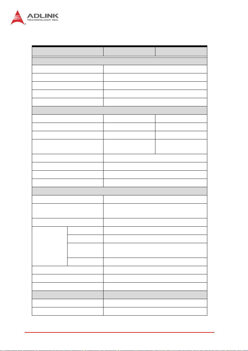
1.3 Specifications
NEON-1020 NEON-1040
Processing & Memory
Processor Quad core Intel Atom E3845 @ 1.91GHz
Display VGA output, max 2560x1600 at 60 Hz.
RAM 2GB DDR3L
Storage 8 to 32 GB solid state drive
Advanced Processing ROI, LUT, Shading Correction
Sensor
Image Sensor CMV2000 CMV4000
Resolution 2048 x 1088 2048 x 2048
Sensor Size 2/3” 1”
Frame Rate
Format Monochrome
Pixel Size (μm) 5.5
Shutter Global
Trigger Mode External trigger, software trigger, free run
I/O
Trigger Input 1x Opto-isolated trigger input
Digital Output
Digital Input 4x TTL level input
Drive Method Constant current 500 mA
PWM
Lighting
Control
Ethernet 1 x GbE
Serial Communication 1 x RS-232 (TX and RX only)
USB 1 x USB 2.0
Physical
Dimensions 68.5W x 110D x 52.7H mm
Lens mount C mount
Intensity PWM control, max. 125 KHz
Applicable
Light Units
20KHz 1000 steps
120fps (8bit)
60fps (12bit)
4x sink type output, max sink 100mA
sink voltage max 30VDC
12 VDC to 24 VDC illuminators
60fps (8bit)
30fps (12bit)
2Introduction
Page 13

NEON-1020/1040
NEON-1020 NEON-1040
Connectors
Software
OS
Environmental & Electrical
Power Consumption 12 to 24 VDC +/-10%, 13W (typical)
Operating Temperature 0 to 50°C
Vibration Operating, 5 Grms, 5-500 Hz, 3 axes
Certification IP67, CE, FCC Class A
1xM12 8-pin female, 1xM12 17-pin male,
1x M12 12-pin male
Windows 7, Windows Embedded Standard
7
Introduction 3
Page 14

1.4 Schematics
X All units are in millimeters (mm)
X External dimensions for the NEON-1020 and
NOTE:
NOTE:
71.5
30
NEON-1040 are identical
68.5
35.5
110
127.3
36
Figure 1-1: NEON-1040 Front View
4Introduction
Page 15

5.95
NEON-1020/1040
98.1
50
Figure 1-2: NEON-1020/1040 Rear View
Introduction 5
Page 16

65.2
1.50
Figure 1-3: NEON-1020/1040 Side View
6Introduction
52.7
Page 17

NEON-1020/1040
1.5 Indicators
Figure 1-4: NEON-1020/1040 LED Array
The NEON 1020/1040 provides five labeled LED indicators on the
top side, with function as follows.
Indicator Color Status Description
POWER Blue
STATUS Red
LAN ACT Green
USER1 Orange On/Off/ Flashing User defined LED1
USER2 Green On/Off/ Flashing User defined LED2
Table 1-1: NEON-1020/1040 LED Function
On System power on
Off System power off
On Image capture in progress
Off Image capture idle
On
Off Ethernet port disconnected.
Flashing
Ethernet port connected and
inactive
Ethernet port connected and
active
Introduction 7
Page 18

1.6 I/O Connectors
A
B C
Figure 1-5: NEON-1020/1040 I/O Array
A Power/IO/UART
B Ethernet
C VGA/USB
Table 1-2: NEON-1020/1040 I/O Array Legend
8Introduction
Page 19

1.6.1 Digital I/O and Power
Figure 1-6: Digital I/O and Power Connector
NEON-1020/1040
Pin Signal Type Description
1 RS232 RXD Input RS-232 receive. Brown
DO3/
2
Strobe out 3
DO1/
3
Strobe out 1
Hardware
4
trigger input
(+)
Hardware
5
trigger input
(-)
PWM light
6
control out (+)
Introduction 9
Output
Output
Input
Input
Output
Open-collector output 3
or strobe out 3
Open-collector output 1
or strobe out 1
Hardware Trigger input
positive
Hardware Trigger input
negative
PWM LED control out
positive, for
connection to LED
lighting device; Power
source of LED current
control is shared
System PWR
17-Pin M12
Pigtail
Blue
White
Green
Pink
Yell ow
Page 20

Pin Signal Type Description
17-Pin M12
Pigtail
PWM LED control out
negative, for
connection to LED
lighting device; Power
source of LED current
Black
7
PWM light
control out (-)
Output
control is shared
System PWR
Power input w/ input
8 System PWR Input
range +12V ~ +24V
Gray
+/-10%
Power input w/ input
9 System PWR Input
range +12V ~ +24V
Red
+/-10%
10 RS232 TXD Output RS-232 transmit Violet
DO2/
11
12
Strobe out 2
DO0/
Strobe out 0
Output
Output
13 DI3 Input
14 DI0 Input
15 DI2 Input
16 DI1 Input
Open-collector output 2
or strobe out 2
Open-collector output 0
or strobe out 0
Digital input signal
source 3
Digital input signal
source 0
Digital input signal
source 2
Digital input signal
source 1
Gray/Pink
Red/Blue
White/Green
Brown/Green
White/Yellow
Yellow/Brown
Ground, reserved for
17 GND GND
use with ground from
White/Gray
power supply
Table 1-3: Digital I/O and Power Pin Assignment
The negative pin of Digital OUT and Digital IN is GND.
NOTE:
NOTE:
10 Introduction
Page 21

NEON-1020/1040
1.6.2 100/GbE
M12 8-pin (female) connector that provides communication capabilities at 10 Mbit/sec, 100 Mbit/sec, or 1 Gbit/sec(1000 Mbit/sec).
Figure 1-7: 100/GbE Connector
Pin Signal Description
1 MDI_3- Data C-
2 MDI_4+ Data D+
3 MDI_4- Data D-
4 MDI_1- Data A-
5 MDI_2+ Data B+
6 MDI_1+ Data A+
7 MDI_3+ Data C+
8 MDI_2- Data B-
T able 1-4: 100/GbE Pin Assignment
Introduction 11
Page 22

1.6.3 VGA/USB
M12 12-pin (male) connector that transmits output video and USB
2.0 signals. The output video signal is a standard RGB analog
video output transferring the OS desktop to connected independent display devices. The video output can display an extended
Windows and/or an exclusive display.
Figure 1-8: VGA/USB Connector
Pin Signal Type Description
1 USB Power Output
2 USB DATA (+) Bidirectional USB data +
3 USB_DATA (-) Bidirectional USB data -
4 GND GND Ground
5 VGA RED Output Red of RGB video signal
6 VGA BLUE Output Blue of RGB video signal
7 VGA VSYNC Output
12 Introduction
5 V supplied to USB
peripherals
Vertical sync of RGB
video signal
Page 23

NEON-1020/1040
Pin Signal Type Description
8 VGA HSYNC Output
9 VGA GREEN Output
Horizontal synch of RBG
video signal
Green of RGB video
signal
10 GND GND Ground
11 VGA DDC SCL Bidirectional DDC serial clock line
12 VGA DDC SDA Bidirectional DDC serial data line
Table 1-5: VGA/USB Pin Assignment
1.7 General Purpose Digital Signals
1.7.1 General Purpose Digital Output (EDO)
Four digital output channels are provided, such that, in the common ground connection of digital output, as shown, when a 1
(logic high) is written by FPGA to a DO channel, sink current
passes through the transistors and the DO channel goes low, and
when a 0 (logic low) is written by FPGA to a DO channel, no current passes through the transistors and the DO channel goes high.
Max 100 mA
DOn
Max. 30VDC
GND
Figure 1-9: General Purpose Digital Output (EDO) Circuit
Introduction 13
Page 24

1.7.2 General Purpose Digital Input (EDI)
Four digital input channels are provided.
DIn
Max 6VDC
GND
1k
Figure 1-10: General Purpose Digital Input (EDI) Circuit
1.7.3 Hardware Trigger Input
Four digital input channels are provided.
Hardware Trigger input (+)
Max. 6VDC
Hardware Trigger input (-)
Figure 1-11: Hardware Trigger Input Circuit
1k
NEON-1020/1040
1.7.4 PWM Light Control Output
One channel constant-current sink LED driver, constant 500mA
output current with 1000 level light control controls brightness of
LED lighting devices, sharing the NEON-1020/1040 System PWR
input, requiring that System PWR voltage matches the LED lighting device's operating voltage.
14 Introduction
Page 25

NEON-1020/1040
System PWR
PWM LED control out (+)
Max. 500 mA
Neon-1020/1040
PWM controller
PWM LED control out (-)
Figure 1-12: PWM Light Control Output Circuit
LED Light
Introduction 15
Page 26

This page intentionally left blank.
16 Introduction
Page 27

NEON-1020/1040
2 Getting Started
This chapter describes connection and configuration of the
NEON-1020/1040.
2.1 Unpacking Checklist
Before unpacking, check the shipping carton for any damage. If
the shipping carton and/or contents are damaged, inform your
dealer immediately. Retain the shipping carton and packing
materials for inspection. Obtain authorization from your dealer
before returning any product to ADLINK. Ensure that the following items are included in the package.
X NEON-1020/1040
X Quick Start Guide
2.2 Connecting a VGA/USB cable
1. Align the alignment pin (device side) with the alignment
channel (cable side)
Figure 2-1: VGA/USB Alignment Pin (device side)
2. Fully insert the cable connector.
3. Tighten the threaded collar (cable side) to fix the connection.
Getting Started 17
Page 28

2.3 Connecting an Ethernet cable
1. Align the alignment pin (cable side) with the alignment
channel (device side)
Figure 2-2: Ethernet Alignment Channel (device side)
2. Fully insert the cable connector.
3. Tighten the threaded collar (cable side) to fix the connection.
18 Getting Started
Page 29

NEON-1020/1040
2.4 Connecting a power cable
1. Align the alignment pin (device side) with the alignment
channel (cable side)
Figure 2-3: Power Alignment Pin (device side)
2. Fully insert the cable connector.
3. Tighten the threaded collar (cable side) to fix the connec-
tion.
2.5 Operating System Installation
The NEON-1020/1040 is compatible with Windows Embedded
Standard 7 (WES7E),and supports File-Based Write Filter
(FBWF), providing a stable, secure, and high performance
software operating environment. The device OS is pre-installed.
For other OS support, please contact ADLINK directly.
2.6 Driver Installation
While the following describes NEON-1020/1040 driver installation
for WES 7 and Windows 7, with other Windows systems following
similar procedures.
1. Run Setup, installation begins.
Getting Started 19
Page 30

2. Select Next when prompted until installation is complete.
20 Getting Started
Page 31

NEON-1020/1040
Getting Started 21
Page 32

3. If a Security Warning window appears, select “Install this
driver anyway”.
22 Getting Started
Page 33

NEON-1020/1040
4. If a “Found New Hardware Wizard” window appears,
ignore and the window automatically closes after installation is complete.
5. When installation is complete, select Finish.
Getting Started 23
Page 34

The device should appear in the Device Manager, as shown
24 Getting Started
Page 35

NOTE:
NOTE:
NEON-1020/1040
If an error occurs and installation is rolled back, e-mail
the file setupapi.log in the Windows folder to ADLINK.
Log files on Vista systems are moved to %windir%\inf
and renamed to setupapi.app.log and setupapi.dev.log
where windir is the Windows folder.
Getting Started 25
Page 36

This page intentionally left blank.
26 Getting Started
Page 37

NEON-1020/1040
Important Safety Instructions
For user safety, please read and follow all instructions,
WARNINGS, CAUTIONS, and NOTES marked in this manual
and on the associated equipment before handling/operating the
equipment.
X Read these safety instructions carefully.
X Keep this user’s manual for future reference.
X Read the specifications section of this manual for detailed
information on the operating environment of this equipment.
X When installing/mounting or uninstalling/removing
equipment:
Z Turn off power and unplug any power cords/cables.
X To avoid electrical shock and/or damage to equipment:
Z Keep equipment away from water or liquid sources;
Z Keep equipment away from high heat or high humidity;
Z Keep equipment properly ventilated (do not block or
cover ventilation openings);
Z Make sure to use recommended voltage and power
source settings;
Z Always install and operate equipment near an easily
accessible electrical socket-outlet;
Z Secure the power cord (do not place any object on/over
the power cord);
Z Only install/attach and operate equipment on stable
surfaces and/or recommended mountings; and,
Z If the equipment will not be used for long periods of time,
turn off and unplug the equipment from its power source.
Important Safety Instructions 27
Page 38

X Never attempt to fix the equipment. Equipment should only
be serviced by qualified personnel.
A Lithium-type battery may be provided for uninterrupted, backup
or emergency power.
Risk of explosion if battery is replaced with one of an incorrect
type. Dispose of used batteries appropriately.
WARNING:
X Equipment must be serviced by authorized technicians
when:
Z The power cord or plug is damaged;
Z Liquid has penetrated the equipment;
Z It has been exposed to high humidity/moisture;
Z It is not functioning or does not function according to the
user’s manual;
Z It has been dropped and/or damaged; and/or,
Z It has an obvious sign of breakage.
28 Important Safety Instructions
Page 39

Getting Service
Contact us should you require any service or assistance.
ADLINK Technology, Inc.
Address: 9F, No.166 Jian Yi Road, Zhonghe District
New Taipei City 235, Taiwan
ᄅקؑխࡉ৬ԫሁ 166 ᇆ 9 ᑔ
Tel: +886-2-8226-5877
Fax: +886-2-8226-5717
Email: service@adlinktech.com
Ampro ADLINK Technology, Inc.
Address: 5215 Hellyer Avenue, #110
San Jose, CA 95138, USA
Tel: +1-408-360-0200
Toll Free: +1-800-966-5200 (USA only)
Fax: +1-408-360-0222
Email: info@adlinktech.com
ADLINK Technology (China) Co., Ltd.
Address: Ϟ⍋Ꮦ⌺ϰᮄᓴ∳催⾥ᡔು㢇䏃 300 ো(201203)
300 Fang Chun Rd., Zhangjiang Hi-Tech Park
Pudong New Area, Shanghai, 201203 China
Tel: +86-21-5132-8988
Fax: +86-21-5132-3588
Email: market@adlinktech.com
NEON-1020/1040
ADLINK Technology Beijing
Address: ࣫ҀᏖ⍋⎔Ϟഄϰ䏃 1 োⲜ߯ࡼ E ᑻ 801 ᅸ(100085)
Beijing, 100085 China
Tel: +86-10-5885-8666
Fax: +86-10-5885-8626
Email: market@adlinktech.com
ADLINK Technology Shenzhen
Address: ⏅ഇᏖቅ⾥ᡔು催ᮄϗ䘧᭄ᄫᡔᴃು
Tel: +86-755-2643-4858
Fax: +86-755-2664-6353
Email: market@adlinktech.com
LiPPERT ADLINK Technology GmbH
Address: Hans-Thoma-Strasse 11, D-68163
Mannheim, Germany
Tel: +49-621-43214-0
Fax: +49-621 43214-30
Email: emea@adlinktech.com
Rm. 801, Power Creative E, No. 1 Shang Di East Rd.
A1 2 ὐ C (518057)
2F, C Block, Bldg. A1, Cyber-Tech Zone, Gao Xin Ave. Sec. 7
High-Tech Industrial Park S., Shenzhen, 518054 China
Getting Service 29
Page 40

ADLINK Technology, Inc. (French Liaison Office)
Address: 6 allée de Londres, Immeuble Ceylan
91940 Les Ulis, France
Tel: +33 (0) 1 60 12 35 66
Fax: +33 (0) 1 60 12 35 66
Email: france@adlinktech.com
ADLINK Technology Japan Corporation
Address: ͱ101-0045 ᵅҀ䛑ҷ⬄⼲⬄䤯ފ⬎ 3-7-4
Tel: +81-3-4455-3722
Fax: +81-3-5209-6013
Email: japan@adlinktech.com
ADLINK Technology, Inc. (Korean Liaison Office)
Address: 137-881 昢殾柢 昢爎割 昢爎堆嵢 326, 802 (昢爎壟, 微汾瘶捒娯)
Tel: +82-2-2057-0565
Fax: +82-2-2057-0563
Email: korea@adlinktech.com
ADLINK Technology Singapore Pte. Ltd.
Address: 84 Genting Lane #07-02A, Cityneon Design Centre
Tel: +65-6844-2261
Fax: +65-6844-2263
Email: singapore@adlinktech.com
ADLINK Technology Singapore Pte. Ltd. (Indian Liaison Office)
Address: #50-56, First Floor, Spearhead Towers
Malleswaram, Bangalore - 560 055, India
Tel: +91-80-65605817, +91-80-42246107
Fax: +91-80-23464606
Email: india@adlinktech.com
⼲⬄ 374 ɛɳ 4F
KANDA374 Bldg. 4F, 3-7-4 Kanda Kajicho,
Chiyoda-ku, Tokyo 101-0045, Japan
802, Mointer B/D, 326 Seocho-daero, Seocho-Gu,
Seoul 137-881, Korea
Singapore 349584
Margosa Main Road (between 16th/17th Cross)
ADLINK Technology, Inc. (Israeli Liaison Office)
Address: 27 Maskit St., Corex Building
PO Box 12777
Herzliya 4673300, Israel
Tel: +972-77-208-0230
Fax: +972-77-208-0230
Email: israel@adlinktech.com
ADLINK Technology, Inc. (UK Liaison Office)
Tel: +44 774 010 59 65
Email: UK@adlinktech.com
30 Getting Service
 Loading...