

Page 1

®
NuDAM
ND-6520 RS-232 to RS-422/RS-485 Converter
ND-6510 RS-422/RS-485 Repeater
ND-6530 USB to RS-485/RS-422/RS-232 Converter
ND-6521 Addressable RS-422/RS-485 to RS-232 Converter
User’s Guide
Recycled Paper
Page 2

© Copyright 1999~2001 ADLINK Technology Inc.
All Rights Reserved.
Manual Rev. 3.00: March 16, 2001
The information in this document is subject to change without prior notice in
order to improve reliability, design and function and does not represent a
commitment on the part of the manufacturer.
In no event will the manufacturer be liable for direct, indirect, special, incidental,
or consequential damages arising out of the use or inability to use the product or
documentation, even if advised of the possibility of such damages.
This document contains proprietary information protected by copyright. All rights
are reserved. No part of this manual may be reproduced by any mechanical,
electronic, or other means in any form without prior written permission of the
manufacturer.
Trademarks
Nudam is registered trademarks of ADLINK Technology Inc.,
Other product names mentioned herein are used for identification purposes only
and may be trademarks and/or registered trademarks of their respective
companies.
Page 3

Table of Contents
Chapter 1 Introduction ....................................................... 1
1.1 WHAT IS NUDAM ?...............................................................................1
1.2 OUTSTANDING FEATURES OF NUDAM..................................................2
1.3 NUDAM-6000 SERIES PRODUCTS OVERVIEW ........................................3
1.4 EIA RS-485 STANDARD ........................................................................4
1.5 RS-485 ON NUDAM .............................................................................4
1.6 NUDAM RS-485 NETWORK CONFIGURATIONS.....................................5
1.7 CONSTRUCTING A NUDAM NETWORK..................................................8
1.8 TERMINATION BUS ................................................................................8
1.9. SHIELDING .............................................................................................9
1.10. HOW TO CALCULATE CHECKSUM VALUE ............................................10
Chapter 2 NuDAM-6520 ....................................................11
2.1. OVERVIEW...........................................................................................11
2.2 SETUP ..................................................................................................16
2.3. INSTALLATION .....................................................................................18
2.4 PROGRAMMING....................................................................................19
Chapter 3 NuDAM-6510 .................................................... 20
3.1. OVERVIEW...........................................................................................20
3.2. SETUP ..................................................................................................24
3.3 INSTALLATION .....................................................................................26
3.4 PROGRAMMING....................................................................................27
Chapter 4 NuDAM-6530 .................................................... 28
4.1. OVERVIEW...........................................................................................28
4.2 SETUP ..................................................................................................33
4.3 INSTALLATION .....................................................................................35
4.4 PROGRAMMING....................................................................................45
Chapter 5 NuDAM-6521 .................................................... 46
5.1. OVERVIEW...........................................................................................46
5.2 INITIALATION & INSTALLATION...........................................................51
5.3. INSTALL A NEW NUDAM-6521 TO A EXISTING NETWORK .................53
5.4 COMMAND SET ....................................................................................54
Table of Concents • i
Page 4

5.4.1 Command and Response....................................................................54
5.4.2 Summary of Command Set.................................................................56
5.4.3 Set Configuration...............................................................................57
5.4.4 Read Configuration ...........................................................................60
5.4.5 Read Module Name............................................................................60
5.4.6 Read Firmware Version.....................................................................62
5.4.7 Soft Reset ...........................................................................................63
5.4.8 Reset Status........................................................................................64
5.4.9 Set RTS Status....................................................................................65
5.4.10 Read RTS Status...............................................................................66
5.4.11 Read CTS Status ..............................................................................67
5.4.12 Set Device ID ...................................................................................68
5.4.13 Read Device ID................................................................................69
5.4.14 Set Delimiter ....................................................................................70
5.4.15 Read Delimiter.................................................................................71
5.4.16 Data Pass.........................................................................................72
5.4.17 Open/Close Data Gate.....................................................................73
5.4.18 Read Command Leading Code Setting .......................................74
5.4.19 Change Command Leading Code Setting........................................75
5.4.20 Set Host Watchdog Timer ................................................................77
5.4.21 Read Host Watchdog Timer.............................................................78
5.4.22 Host is OK........................................................................................79
Chapter 6 Software Utility ................................................ 80
6.1 SOFTWARE INSTALLATION...................................................................80
6.2 HOW TO EXECUTE THE NUDAM ADMINISTRATION ............................80
6.3 NUDAM ADMINISTRATION FUNCTION OVERVIEW..............................81
6.3.1 Change RS-232 Communication Port Setting. .................................81
6.3.2 Search all exist Nudam modules........................................................82
6.3.3 Using Operations...............................................................................83
6.3.4 Save and Print Nudam modules’ information....................................87
6.3.5 Version Information...........................................................................88
TROUBLESHOOTING AND MAINTENANCE..........................................89
PRODUCT WARRANTY/SERVICE.................ERROR! BOOKMARK NOT
DEFINED.
ii • Table of Contents
Page 5

1
Introduction
1.1 What is NuDAM ?
NuDAM is a series of data acquisition modules. It provides a total solution of the
data acquisition network and control system. You can remotely control up to 256
NuDAM modules on RS-485 netowrk. All you need is to use a host computer,
like PC (Personal Computer), with one RS-232 serial port for controlling the
whole system. The maximum communication distance is 4000 feet from the
host computer.
NuDAM is based on the RS-485 multi-drop network system, each module has an
unique address ID. Using simple ASCII command & response protocol through
standard RS-485 interface can control all the NuDAM modules in the RS-485
network.
The NuDAM modules provide direct linkage to a wide variety of sensors and
perform all signal conditioning, scaling, linearization and conversion. The
modules can be used to measure temperature, pressure, flow, voltage, current
and numerous types of digital signals.
Introduction • 1
Page 6

1.2 Outstanding Features of NuDAM
Industry standard networking
z
All NuDAM modules use the RS-485 communication protocol for transmitting
and receiving at high rates and over long distance.
Two-wire and multi-drop communication
z
A single twisted pair of wires is used to transmit and receive data between
modules. Multi-drop capability makes system configuration more flexible and
easy set-up of a network.
High transfer speed
z
NuDAM modules provide up to 115.2K bps data / command transfer rate. It can
promote system bandwidth.
Simple command / response protocol
z
All communications are performed with printable ASCII characters. This allows
the information to be processed with string functions common to the most
high-level languages.
Industrial design
z
The screw terminal plug connectors on every NuDAM module ensures simple
installation and easy modification. The compact size allows the modules to be
mounted on DIN rail, back-panel wall-mount, etc.
Watch-dog supervisory
z
NuDAM contains a watch-dog supervisory circuitry that will automatically reset
the module when the system fails. In addition, a user-programmable software
timer provides a ‘safe’ output signal in the event of host computer failure.
High isolation voltage
z
NuDAM provides photo-isolators, which ensure high isolation voltage, between
the data acquisition circuits and the communication port. The fatal
electric-shock won‘t go through and damage all the modules on the network.
Noise immunity
z
The NuDAM provide extra noise immunity capability. An electrode, which is
coated inside the ABS case, can reduce electro-magnetic interference (EMI)
and noise.
Harsh environmental protection
z
2 • Introduction
Page 7

A surface coating covers on the PCB and electronic components of the NuDAM.
It allows superior resistance to harsh environment such as humidity, salt spry
and most harsh chemicals.
1.3 NuDAM-6000 series products overview
The NuDAM-6000 series provides the complete sets of data acquisition modules,
including the communication modules, the analog input modules, the analog
output modules, and the digital I/O modules.
Communication Module
♦ NuDAM-6510 : RS-422/RS-485 Repeater
♦ NuDAM-6520 : RS-232 to RS-422/RS-485 Converter
♦ NuDAM-6530 : USB to RS-422/RS-485 Converter
♦ NuDAM-6521 : Addressable RS-422/RS-485 to RS-232 Converter
Analog Input Modules
♦ NuDAM-6011: Multifunction High Gain Analog Input Module(with
DI/O)
♦ NuDAM-6011D: Multifunction High Gain Analog Input with 5 ½ digit
LED Display(with DI/O)
♦ NuDAM-6012: Analog Input Module(with DI/O)
♦ NuDAM-6012D: Analog Input Module with 5 1/2 digit LED Display(with
DI/O)
♦ NuDAM-6013: 3-channel RTD Input Module
♦ NuDAM-6014D: Analog (Transmitter) Input Module with 5 1/2digit
LED Display
♦ NuDAM-6017: 8-channel Analog Input Module
♦ NuDAM-6018: 8-channel Thermocouple Input Module
Analog Output Modules
♦ NuDAM-6021: Single Channel Analog Output Module
♦ NuDAM-6024: 4-channel Analog Output Module(with DI)
Digital I/O Modules
♦ NuDAM-6050 : Module with 7 DI channels and 8 DO channels
♦ NuDAM-6052 : Isolated Digital Input Module
♦ NuDAM-6053 : 16-channel digital Input Module
♦ NuDAM-6054 : 15-channel digital Input Module
♦ NuDAM-6056 : 15-channel digital Output Module
♦ NuDAM-6058 : 28-channel programable digital I/O Module
♦ NuDAM-6060 : 4-channel Relay Output & Digital Input Module
Introduction • 3
Page 8

♦ NuDAM-6063 : 8-channel Relay Output Module
♦ NuDAM-6080 : Counter/Frequency Input Module
1.4 EIA RS-485 Standard
The EIA RS-485 interface is a communication standard developed for
multi-dropped systems that can communicate at high rate over long distance.
The standard RS-485 can operate at speed up to 10 M bps over cable length up
to 4000 feet.
The RS-485 interface can support up to 32 drivers / receivers on the same line.
This allows actual networking applications on a parity line system (sometimes
called multi-drop).
The RS-485 uses differential transmission on a balance line. Its easy wiring
make it popular to use in industrial applications.
1.5 RS-485 on NuDAM
The NuDAM improves the RS-485 capability for minimizing the user‘s cost. On
each NuDAM module, a half-duplex RS-485 transceiver is used to communicate
with other modules. A single twisted pair of wires, which provides standard
differential transmission, is used to transmit and receive data between modules.
The high input impedance of each NuDAM receiver allows up to 128 NuDAM
modules on the same RS-485 bus without using a signal repeater.
The maximum transfer rate of NuDAM is 115.2Kbps which is lower than the
maximum speed of the RS-485 standard. The slew-rate limiter on every RS-485
transceiver of NuDAM is very useful for transmitting error-free data, minimizing
EMI, and reducing reflections caused by improperly terminated cables.
The NuDAM on a network may not use the same power supply. Therefore, the
voltage difference between ground of the modules may exist.
Excessive output current and power dissipation caused by faults or by bus
contention are prevented by the current limiter and the thermal shutdown
circuitry inside the NuDAM.
4 • Introduction
Page 9
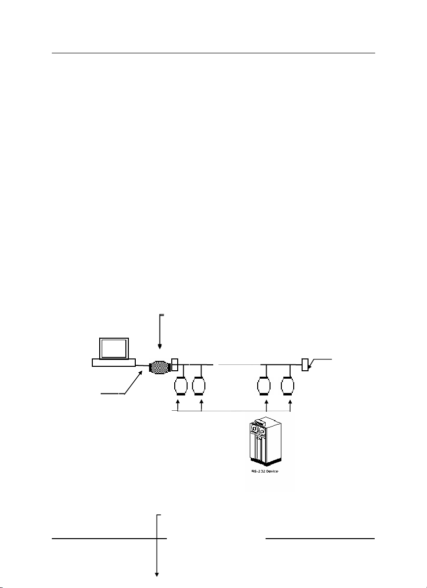
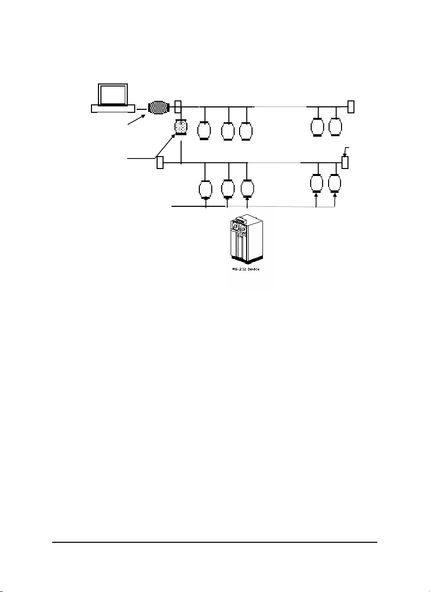
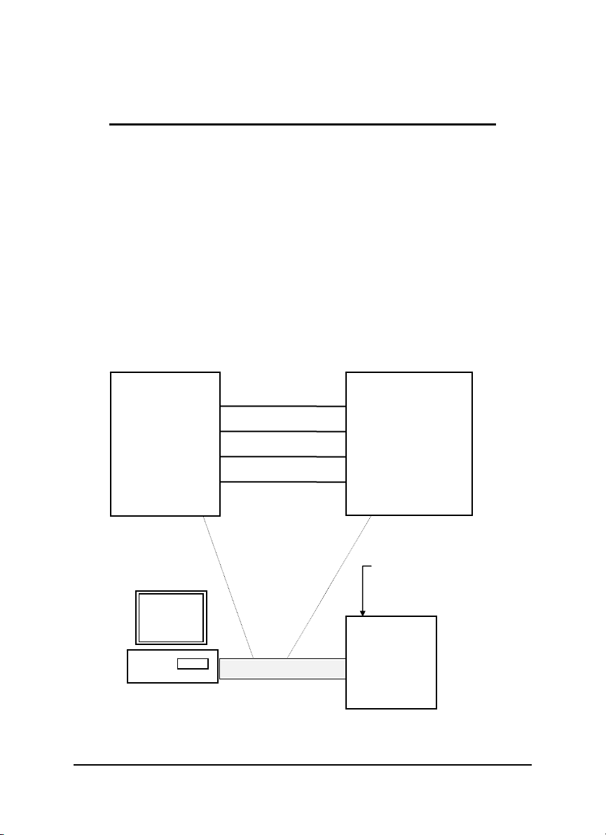
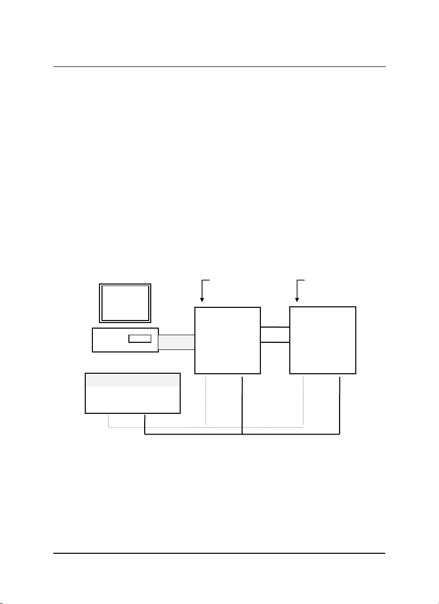
1.6 NuDAM RS-485 Network Configurations
T
r
NuDAM-6000 series is designed under RS-485 multi-drop network architecture.
Up to 256 NuDAM modules can be controlled in a multi-drop network. The limit
of 256 is due to command code. The network can be connected by simple
topology (Figure 1-1) or branch topology (Figure 1-2) or free topology (Figure
1-3).
The ND-6520 and ND-6510 are the two basic communication modules to
construct a RS-485 network. The ND-6520 is a RS-232 to RS-485/RS-422
converter. The ND-6520 is used to build a RS-485 port for the host computer by
converting standard RS-232 signal into RS-485 signal.
The ND-6510 is the RS-485 signal repeater which is used to extend or to
lengthen the network distance. A NuDAM bus can connect up to 256 modules,
each segment is up to 128 modules. Whenever the numbers of the modules
excess 128, the repeater should be used. In addition, the length of a standard
RS-485 bus is up to 4000 feet, the repeater should be used whenever the length
of a signal bus is more than 4000 feet.
The ND-6530 is the USB to RS-485/RS-422/RS-232 converter, and it used to
build the USB signal into RS-485/RS-422/RS-232 signal.
The ND-6521 is an addressable RS-485/RS-422 to RS-232 converter, it allows
the RS-232 devices easily link to Host by the RS-485/422 bus.
Host
RS-232
NuDAM Modules
ND-6520: RS-232 to
ND-6520
RS-485/RS-422
RS-232/RS-485
ND-6530: USB to
Converter
RS-232/RS485/RS-422
Converter.
RS-485 bus
Converter
erminato
ND-6521
Figure 1-1 Simple Topology
ND-6520: RS-232 to
RS-485/RS-422
ND-6530: USB to
RS-232/RS485/RS-422
Converter.
Converter
Introduction • 5
Page 10
T
r
Host
RS-232
ND-6510
Repeater
RS-485 bus
RS-485 bus
erminato
NuDAM Modules
ND-6521
6 • Introduction
Figure 1-2 Branch Topology
Page 11
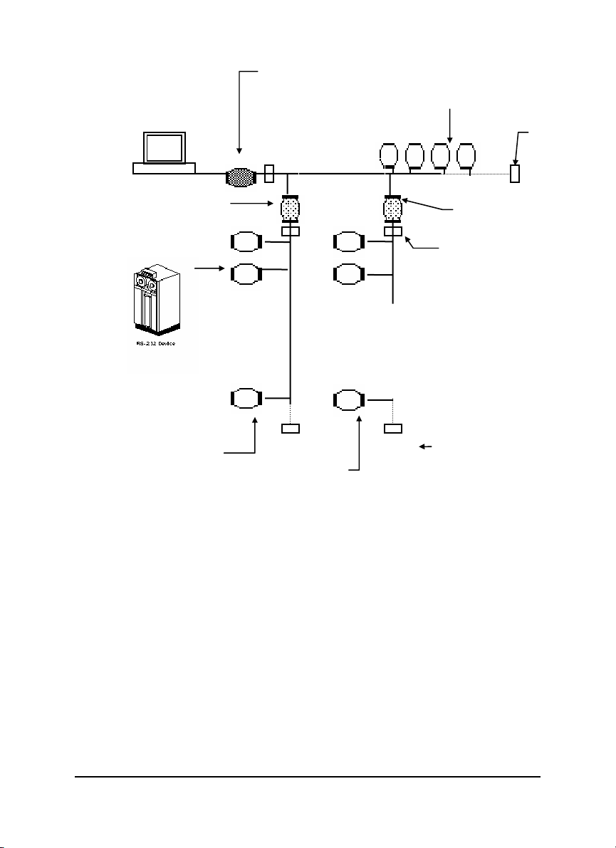
ND-6520: RS-232 to
T
r
T
r
T
r
Host
ND-6510
Repeater
RS-485/RS-422
ND-6530: USB to
RS-232/RS485/RS-422
Converter.
RS-485 bus
ND-6521
Converter
NuDAM Modules
ND-6510
Repeater
erminato
erminato
NuDAM I/O
modules
NuDAM I/O modules
Figure 1-3 Free Topology
erminato
Introduction • 7
Page 12
1.7 Constructing a NuDAM Network
Go through the following steps, the user can construct a NuDAM network easily.
1. Setup a ND-6520 or ND-6530.
2. Connect the host computer with the ND-6520 or ND-6530.
3. Setup one or more ND-6510 if necessary.
4. Connect the ND-6510 to extend to RS-485 bus if necessary.
5. Install the NuDAM utility software or ND-6530 driver from disk.
6. Initialize the brand-new NuDAM modules.
7. Add the new NuDAM modules into RS-485 network.
Refer to chapter 2 and chapter 4 for executing step 1 and 2. Refer to chapter 3
for executing step 3, 4 and for understanding the time to install ND-6510. The
knowledge about the software for operating the NuDAM is in chapter 6. For
executing the step 6 and step 7, please refer to the install procedures of each
module and chapter 6.
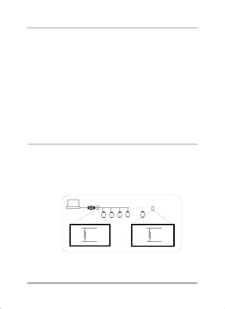
1.8 Termination Bus
In order to avoid signal reflections on the bus, each bus segment has to be
blanked off at its physical beginning and at its end with the characteristic
impedance. An termination resister ( Rt) is intalled for this purpose. The Rt value
- 120Ω ± 2% is recommended, and the detailed connection of Rt can be referred
from the “Terminator Connection” diagram below.
8 • Introduction
Host
Data+
Data-
120 ohms
Data+
Data-
Terminator Connection
120 ohms
Page 13
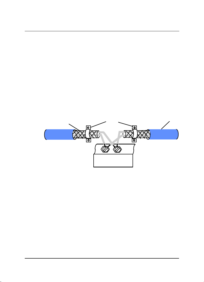
1.9. Shielding
In case of increased interference, a shielded bus cables is recommended to use
for wiring between module and modules. In addition, a shielding also should be
done for the cable of power supply and for the signal cables.
Some experiences and recommendations are concerning for shield connection.
1. The shield should be connected with protective earthing at each bus
connection.
2. The shield should be applied additionally several times along the course of the
cable.
3. The Computer should be applied the shield directly to the appliance or to
separate shield rails.
braided shield
RS-485 Connection Cable
Earthing Point
DATA+
DATA -
Isolation
NuDAM Module
Introduction • 9
Page 14

1.10. How to Calculate Checksum Value
Format of NuDAM Commands
(LeadingCode)(Addr)(Command)(Data)
When checksum is enable then [Checksum] is needed, it is 2-character.
[Checksum] =
Example 1: checksum is
Example 2: checksum is
B7 = (
0x24 + 0x30 + 0x31 + 0x32
AC= (
0x24+ 0x30+ 0x31+ 0x34+ 0x30+ 0x30+ 0x36+ 0x30+ 0x30)
(LeadingCode)+(Addr)+(Command)+(Data)
(
disable
User Command : $012<CR>
Response : !01400600
enable
User Command :
Response :
‘$’ = 0x24 ‘0’ = 0x30 ‘1’ = 0x31 ‘2’ = 0x30
‘!’ = 0x24 ‘0’ = 0x30 ‘1’ = 0x31 ‘4’ = 0x34
‘6’ = 0x36
[Checksum]
$012B7<CR>
!01400600AC
) MOD 0x100
<CR>
) MOD 0x100
MOD 0x100
10 • Introduction
Page 15

2
NuDAM-6520
2.1. Overview
What is NuDAM-6520 ?
NuDAM-6520 is a RS-232 to RS-422/RS-485 converter, it converts the RS-232
signal to the RS-422/RS-485 signals. The ND-6520 can be considered as an
extension RS-422/RS-485 serial port for the host computer. A standard 9-pin
D-type connector is used to connect the host computer and the ND-6520.
Hence, the ND-6520 can connect with all kinds the PC, IPC or Notebook PC,
which install a standard RS-232 interface.
Features of NuDAM-6520
♦ RS-422/RS-485 transceiver
♦ Differenial 2-wire half-duplex RS-485
♦ Easily setup and installation
♦ Auto direction flow control
♦ Maximum 128 NuDAM on a bus without using repeaters
♦ Maximum 256 addressable NuDAM modules
♦ High transfer speed
♦ High isolation voltage
♦ Lower power consumption
NuDAM-6520 • 11
Page 16

Specifications of NuDAM-6520
Input
♦ Interface : standard RS-232 9 pin female D-type connector
♦ Speed (bps) : 1200(115.2K
1
), 2400, 4800, 9600, 19.2K, 38.4K, RTS
♦ Data Format : 9 bits, 10 bits, 11 bits, or 12 bits
Output
♦ Interface :RS-485, differential, 2 half-duplex wires RS-422, differential,
4 full-duplex wires
♦ Speed (bps) : 1200(115.2K
1
), 2400, 4800, 9600, 19.2K, 38.4K, RTS
♦ Max RS-485 network bus distance : 4000 ft. (1200m)
Isolation
♦ Isolation voltage : 5000 Vrms(between RS-422/RS-485 network and
host computer)
Bus
♦ Max loading : 128 NuDAMs on a RS-485 network
♦ Max modules : 256 NuDAMs with one ND-6510 repeater
Power
♦ Power Supply : +10V to +30V
♦ Power Consumption : 0.95 W
Note 1: 115.2K is supported by Firmware version A1.2 or later.
12 • NuDAM-6520
Page 17

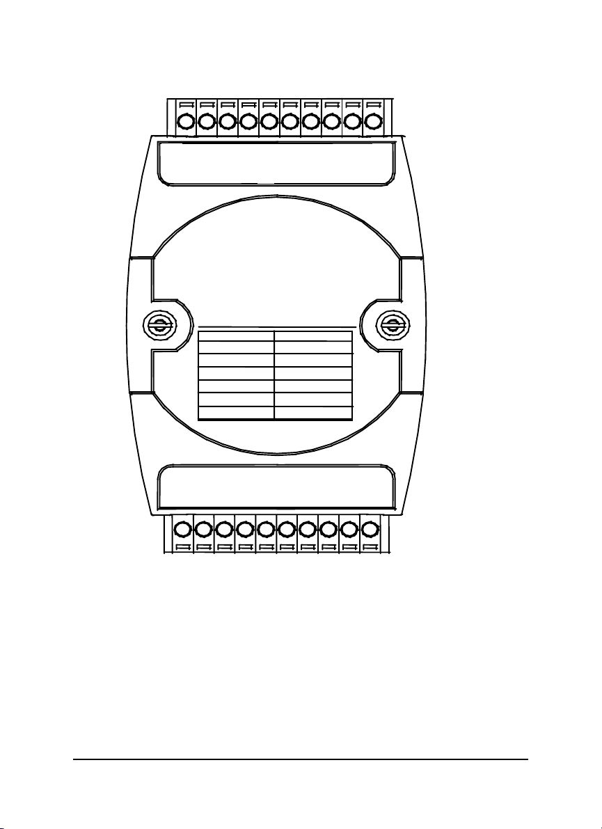
A Look at NuDAM-6520 & Pin Assignment
(
)
N
(Y) DATA+
)
bp
bp
RS-232 IN
RS-232 to RS-485
D-6520
Switch Position
SW1: ON
SW2: ON
SW3: ON
SW4: ON
SW5: ON
SW6: ON
SW7: ON
/RS-422Converter
Baud Rate
RTS CTRL
115.2K bps
2400
s
4800 bps
9600 bps
19.2K bps
38.4K
s
DATAG
TX-
TX+
RX+
TX-
(B)GND
(R)+Vs
NuDAM-6520 • 13
Page 18
Pin Definitions
r
Pin # Signal Name Description
1 (Y)DATA+ RS-485 transmission line, positive
2 (G)DATA- RS-485 transmission line, negative
4 TX+ RS-422 transmission line, positive
5 TX- RS-422 transmission line, negative
6 RX+ RS-422 receiving line, positive
7 RX- RS-422 receiving line, negative
9 (R)+VS NuDAM power supply, +10V~+30V
10 (B)GND NuDAM ground
-- RS-232 IN 9-pin RS-232 connector
Connection Between Host and ND-6520
Host RS-232
RTS t
GND r
TXD p
RXD o
Host
Computer
RS-232
ND-6520 RS-232
i RTS
g GND
e TXD
d RXD
NuDAM-6520
RS-232/RS-485
Converte
DATA +
DATA -
+Vs GND
14 • NuDAM-6520
Page 19
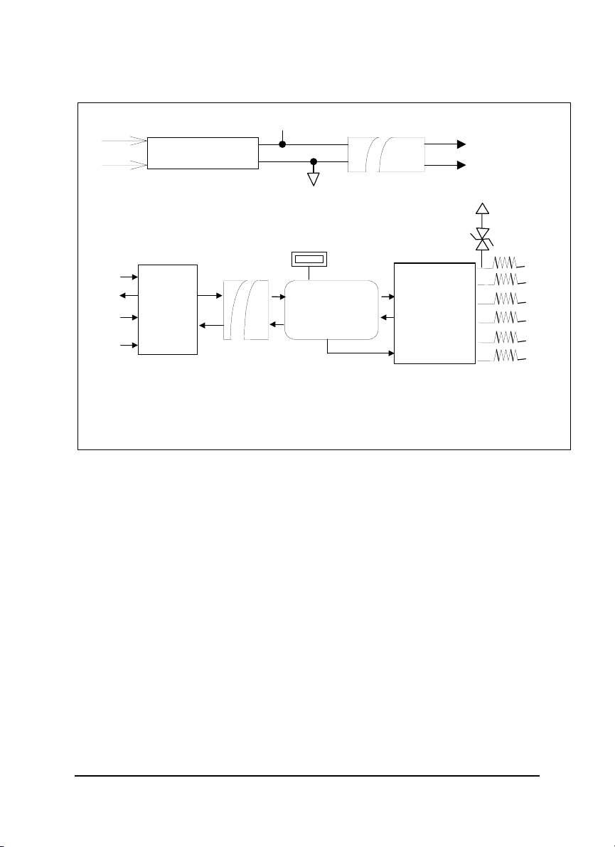
Functional Block Diagram
r
r
r
p
VS
Power Regulato
& Filte
Power Input
+10V ~ +30V
+5V
GND
Isolation +5V
Isolation GND
DC to DC
Converte
TXD
RXD
RTS
RS-232
Receiver
/ Driver
GND
Opto-Isolation
TVS : Transient Voltage Suppresser
PTC : Positive Tem
SW1
Communication
Switching
Controller
Communication
Direction Control
erature Coefficient
T
RS-422/RS-485
Receiver/Driver
PTC
Data+
Data-
Rx+
Rx-
Tx+
Tx-
NuDAM-6520 • 15
Page 20

2.2 Setup
Objective of Setup
In normal condition, it is not necessary to setup the NuDAM-6520. The default
configuration of this communication module is 9600 bps and data format of 8
data bits with 1 start bit, 1 stop bit, and no parity check. Note that the data format
is reserved to be compatible with other brand‘s communication port, it should not
be modified if only NuDAM is used in a system. The baud rate can be
configured according applications’ requirement.
Setup Equipments
Only screw driver is used to open the case. Software, power supply, and wiring
are not necessary.
Setup Procedure
Only hardware switch setting can be setup in ND-6520. The user can set the
speed of the serial interface ( RS-232 and RS-422/RS-485 ), and the serial data
format. The speed and the data format on the whole RS-485 network must be
identity otherwise the communication will be not correct.
To setup the ND-6520, use the screw driver to open the case, then change the
switch setting. The new setting is available after power on. The case must be
put back and locked carefully. Note that do not scratch the surface of the circuit
while setting up, otherwise the surface coating or even the circuits will be
damaged.
(Note: For Harware Rev.C1 or upper, there is switchless for
Baudrate adjust. It is auto baudrate and parity, data bits
adjust.)
Default Setting
♦ 9600 baud rate
♦ 10 bits series data format : one start bit, eight data bits, one stop bit,
no parity check
16 • NuDAM-6520
Page 21
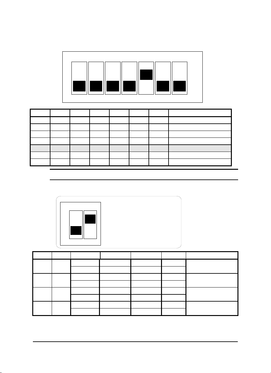
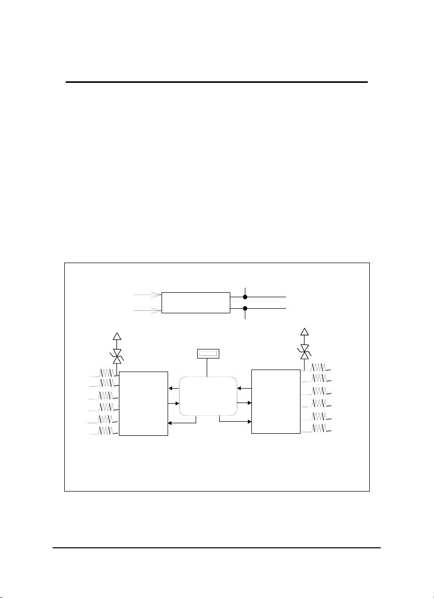
SW1 Setting
g (
)
p
SW 1 D efault S e ttin
ON
1 2 3 4 5 6 7
OFF
9600 bps
1 2 3 4 5 6 7 Baud Rate
ON OFF OFF OFF OFF OFF OFF RTS Control
OFF ON OFF OFF OFF OFF OFF 1200 or 115.2k1 bps
OFF OFF ON OFF OFF OFF OFF 2400 bps
OFF OFF OFF ON OFF OFF OFF 4800 bps
OFF OFF OFF OFF ON OFF OFF 9600 bps
OFF OFF OFF OFF OFF ON OFF 19200 bps
OFF OFF OFF OFF OFF OFF ON 38400 bps
Note 1: 115.2kbps is supported by version A1.2 or later.
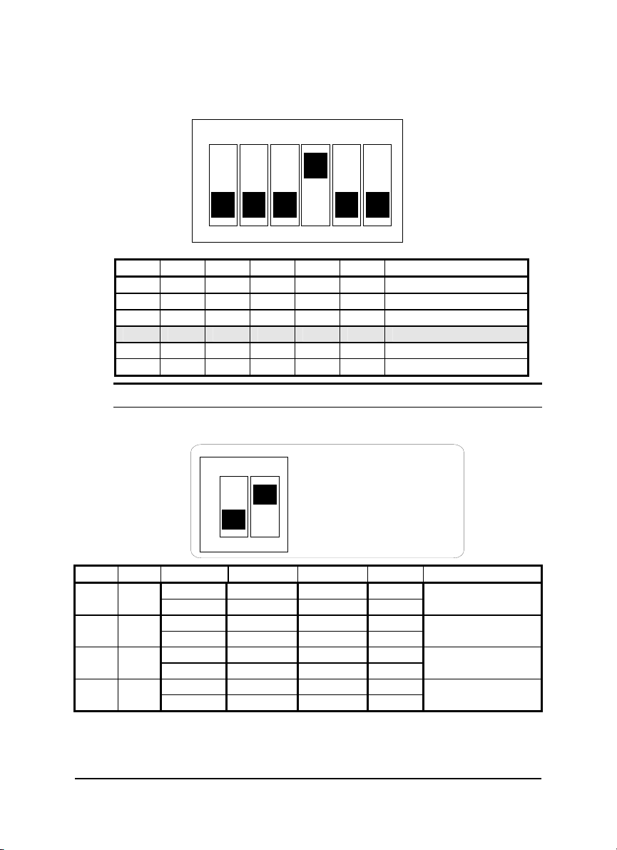
SW2 Setting
ON
12
S W 2 D e fa u lt Settin g
S tart B its : 1
Data Bits : 8
Sto
Bits : 1
P arity : N o n e
1 2 Start Bit Data Bits Stop Bit Parity Packet Data Bits
1 7 1 0 OFF OFF
9
1 6 1 1
1 8 1 0 OFF ON
10
1 7 1 1
1 9 1 0 ON OFF
11
1 8 1 1
1 10 1 0 ON ON
12
1 9 1 1
NuDAM-6520 • 17
Page 22
2.3. Installation
r
Software Utility
Software is not necessary for this module.
Equipments for Installation
A host computer with RS-232 port
RS-232 cable (DB-9 female)
DC Power supply (+10V~+30V) (NDP-243u is recommended)
Wires (shielded and grounded is recommended)
Installation Procedure
1. Make sure the host computer is power off.
2. Use RS-232 cable to connect NuDAM-6520 with host computer.
3. Wire the power supply to NuDAM. Note that the power supply should meet
the specification.
4. Wire other NuDAMs.
Application Wiring
The Figure 2-1 shows the application wiring of NuDAM-6520.
Host
Computer
RS-232
Local Power Supply
+10 V to +30 V
+Vs GND
Figure 2-1 Application wiring of NuDAM-6520
NuDAM-6520
RS-232/RS-485
Converte
DATA +
DATA -
+Vs GND
NuDAM
module
+ DATA
- DATA
+Vs GND
18 • NuDAM-6520
Page 23

2.4 Programming
The NuDAM-6520 is a communication module, it is not necessary to be
programmed
NuDAM-6520 • 19
Page 24

3
NuDAM-6510
3.1. Overview
What is NuDAM-6510 ?
The ND-6510 is the RS-422/RS-485 signal repeater which is used to extend or
to lengthen the network distance. A NuDAM bus can connect up to 128 modules.
The repeater should be used when the numbers of the modules excess 128. In
addition, the repeater should also be used when the length of a signal bus is
more than 4000 feet.
Features of NuDAM-6510
z RS-422/RS-485 signal transceiver & repeater
z Bi-directions signal transmission for both RS-422/RS-485 ports
z Automatic transmission direction control
z Easily setup and installation
z Maximum 128 NuDAM on a bus
z Maximum 256 addressable NuDAM modules
z High transfer speed
z Surge protection
z Lower power consumption
Specifications of NuDAM-6510
20 • NuDAM-6510
Page 25

Input / Output
♦ Interface : RS-485, differential 2 half-duplex wires RS-422, differential, 4
full-duplex wires
♦ Speed (bps) : 1200(115.2K
1)
, 2400, 4800, 9600, 19.2K, 38.4K
♦ Data Format : 9 bits, 10 bits, 11 bits, or 12 bits
♦ Max RS-485 network bus distance : 4000 ft. (1200m)
Note 1: 115.2k is supported by version A1.2 or later.
Bus
♦ Max Loading : 128 NuDAMs on a bus
Power
♦ DC Power Supply : +10V to +30V
♦ Power Consumption : 0.9 W
NuDAM-6510 • 21
Page 26
A Look at NuDAM-6510 & Pin Assignment
N
)
bp
r
20
DATA+ (Y)
DATA- (G)
D-6510
Switch Position Baud Rate
SW1-1: ON 115.2K bps
SW1-2: ON
SW1-3: ON
SW1-4: ON
SW1-5: ON
SW1-6: ON
DATAG
(Y)DATA+
Tx+
Rx-
Rx+
RS-422/RS-485
Repeapte
2400
s
4800 bps
9600 bps
19.2 K bps
38.4 K bps
RX-
Rx+
Tx-
11
(R)+Vs
(B)GND
22 • NuDAM-6510
Page 27
Pin Definitions
r
r
V
V
D
r
+
n
g
r
+
Pin # Signal Name Description
1 (Y)DATA+ RS-485 transmission line, positive
2 (G)DATA- RS-485 transmission line, negative
4 TXIN+ RS-422 transmission input line, positive
5 TXIN- RS-422 transmission input line, negative
6 RXOUT+ RS-422 receiving output line, positive
7 RXOUT- RS-422 receiving output line, negative
9 (R)+VS NuDAM power supply, +10V~+30V
10 (B)GND NuDAM ground
14 RXIN- RS-422 receiving input line, negative
15 RXIN+ RS-422 receiving input line, positive
16 TXOUT- RS-422 transmission output line, negative
17 TXOUT+ RS-422 transmission output line, positive
19 (G)DATA- RS-485 transmission line, negative
20 (Y)DATA+ RS-485 transmission line, positive
ND-6510 Functional Block Diagram
+5
Power Input
+10V ~ +30
Power Regulato
& Filte
GN
Data
Data-
Rx+
Rx-
Tx+
Tx-
RS-422/RS-485
Receiver/Dr iver
SW1
Communicatio
Switchin
Controlle
Communication
T
RS-422/RS-485
Receiver/Dr iver
PTC
Data
Data-
Rx+
Rx-
Tx+
Tx-
Direction
Control
TVS : Transient Voltage Suppresse
PTC : Positive Temperature Coefficient
NuDAM-6510 • 23
Page 28

3.2. Setup
Objective of Setup
In normal condition, it only needs to setup the NuDAM-6510 when the NuDAM
bus with more than 128 modules or the distance exceeds 4000 feet long. The
default configuration of this communication module is 9600 bps and data format
of 8 data bits with 1 start bit, 1 stop bit, and no parity check. Note that the data
format is reserved to be compatible with other brand‘s communication port, it
should not be modified if only NuDAM is used in a system. The baud rate can
be configured according user’s requirement.
Setup Equipments
Only screw driver is used to open the case. Software, power supply, and wiring
are not necessary.
Setup Procedure
Only hardware switch setting can be setup in ND-6510. The user can set the
speed and the data format of the RS-422/RS-485 interface. The speed and the
data format on the whole network must be identity otherwise the communication
may be not correct.
To setup the ND-6510, use the screw driver to open the case, then change the
switch setting. The new setting is available after power on. The case must be
put back and locked carefully. Note that do not scratch the surface of the circuit
while setting up, otherwise the surface coating or even the circuits will be
damaged.
(Note: For Harware Rev.C1 or upper, there is switchless for
Baudrate adjust. It is auto baudrate and parity, data bits
adjust.)
Default Setting
♦ 9600 Baud rate
♦ 10 bits serial data format : one start bit, eight data bits, one stop bit, no
parity check
24 • NuDAM-6510
Page 29
SW1 Setting
)
p
SW1 Default Setting (9600 bps
ON
OFF
1 2 3 4 5 6 Baud Rate
ON
OFF
OFF OFF OFF OFF OFF 1200 or 115.2k
ON
OFF OFF
OFF OFF OFF
OFF OFF OFF OFF
OFF OFF OFF OFF OFF
2 3 4 5 6
1
OFF OFF OFF OFF 2400 bps
ON
OFF OFF OFF 4800 bps
ON
OFF OFF 9600 bps
ON
OFF 19200 bps
ON
38400 bps
1
bps
Note 1: 115.2kbps is supported by version A1.2 or later.
SW2 Setting
ON
12
S W 2 D e fa ult S e ttin g
S tart B its : 1
D ata B its : 8
B its : 1
Sto
P ar ity : N o n e
1 2 Start Bit Data Bits Stop Bit Parity Packet Data Bits
1 7 1 0 OFF OFF
1 6 1 1
1 8 1 0 OFF ON
1 7 1 1
1 9 1 0 ON OFF
1 8 1 1
1 10 1 0 ON ON
1 9 1 1
9
10
11
12
NuDAM-6510 • 25
Page 30

3.3 Installation
Software Utility
Software is not necessary.
Equipments for Installation
A 2-wire RS-485 network or 4-wire RS-422 network.
DC Power supply (+10V~+30V)
Wires
Installation Procedure
1. Make sure the original RS-422/RS-485 network is power off.
2. Wire the power supply to NuDAM-6510. Note that the power supply should
meet the specification.
3. Wire other NuDAMs to the extend RS-485 bus.
26 • NuDAM-6510
Page 31

Application Wiring
NuDAM
module
DATA +
DATA -
+Vs GND
+DATA DATA+
-DATA DATA-
Local Power Supply
+10 V to +30 V
+Vs GND
Figure 3-1 NuDAM-6510 wiring.
3.4 Programming
NuDAM-6510
Repeater
+Vs GND
NuDAM
module
+ DATA
- DATA
+Vs GND
The NuDAM-6510 is a communication module, it is not necessary to be
programmed
NuDAM-6510 • 27
Page 32

4
NuDAM-6530
4.1. Overview
What is NuDAM-6530 ?
Universal Serial Bus (USB) is an open, royalty free, Plug and Play standard for
PC peripheral connectivity, supported by leading computer, telecommunications
and software company. It behaves in a similar fashion to conventional bus
technology (serial, parallel, ISA…), but is a faster, no extra slots or IRQ required
manner.
The ND-6530 takes advantages of the USB technology, and for the convenience
to the users of numerous PC, IPC, notebooks, laptops and handheld PC, it
provides an easy way to link with industry standard buses interface of
RS-232/422/485.
Features of NuDAM-6530
z USB Specification 1.1 Compliant
z Plug and Play Installation
z Self power
z RS-232 support RTS CTS handshake signal
z Full-Duplex RS-422 support
z Half-Duplex RS-485 support
28 • NuDAM-6530
Page 33

z Up to 128 RS-485 devices on the bus
z Auto direction flow control on RS-485
z High transfer Speed up to 115.2Kbps
z High isolation voltage up to 2500Vrms
z Surge protection on RS-232/422/485 lines
z Driver support for Windows 2000/98
z Low power consumption
z Easily setup and installation
Specifications of NuDAM-6530
USB controller:
♦ USB Spec. 1.1 compliant
Transceiver:
♦ RS-232: SP385E
♦ RS-422: LT490
♦ RS-485: LT1487
I/O Interface:
♦ RS-232/422/485 DIP switch selectable
♦ RS-232 support RXD, TXD, RTS, CTS, FGND signals
♦ RS-422 support TX+, TX-, RX+, RX- 4 wires full-duplex signals
♦ RS-485 support DATA+, DATA- signals with auto direction control
♦ Selectable transfer speed with 1200, 2400, 4800, 9600, 19200, 38400,
115200 bps
♦ 2500Vrms isolation
♦ Surge protection on all signal lines
Connector:
♦ USB type B
♦ 10 pin screw terminal block
LED Indicator:
♦ ON: Receiving USB power
♦ Flashing: Data transfer
♦ OFF: No power applied
Cable: Type A to type B
NuDAM-6530 • 29
Page 34

Storage Temperature Range: -25 to 80 °C
Operating Temperature Range: -10 to 70 °C
Power Requirement: USB bus power
Power Consumption: 0.6W
Case: ABS with captive mounting hardware
CE Class A Conformity
30 • NuDAM-6530
Page 35

A Look at NuDAM-6510 & Pin Assignment
N
USB to RS-232/422/485
D-6530
Converter
FGND
RX-
RX+
TX-/D-
TX+/D+
TX
RX
CTS
RTS
NuDAM-6530 • 31
Page 36

Pin Definitions
Pin # Signal Name Description
1 TX+/D+ RS-422 or RS-485 transmission line, positive
2 TX-/D- RS-422 or RS-485 transmission line, negative
3 RX+ RS-422 receive line, positive
4 RX- RS-422 receive line, negative
5 NC No connection
6 TX RS-232 transmission line
7 RX RS-232 receive line
8 RTS Request to send
9 CTS Clear to send
10 F.GND Ground
USB Type B connector
1 +5V USB +5V bus power
2 Data- USB data line, negative
3 Data+ USB data line, positive
4 Ground USB bus power ground
ND-6530 Functional Block Diagram
32 • NuDAM-6530
Page 37

4.2 Setup
Objective of Setup
In normal condition, it is not necessary to setup the NuDAM-6520. The default
configuration of this communication module is in RS-485 mode and support
baudrate from 75 to 115200, with data format including 5, 6, 7, 8 or 16 bits, and
its stop bit support 1, 1.5 or 2 bits, parity types are None, Odd, Even, Mark and
Space. Note that the data format is reserved to be compatible with other brand‘s
communication port, it should not be modified if only NuDAM is used in a system.
The baud rate is no needed to config.
Setup Equipments
Only screw driver is used on the dip switch beside the USB connector to select
the protocal type.
Setup Procedure
Only hardware switch setting can be setup in ND-6530. The user can select the
portocal types in RS-422, RS-485 or RS-232 interface. The speed and the data
format on the whole network must be identity otherwise the communication may
be not correct.
To setup the ND-6530, use the screw driver to adjust the dip switch beside the
USB connector to select the protocal type. The new setting is available even
power on. The case will not be open.
NuDAM-6530 • 33
Page 38

Default Setting
RS-485 Interface
z
DIP Switch Setting
RS-485 (Default)
RS-422
RS-232
34 • NuDAM-6530
Page 39

4.3 Installation
Software Utility
ND-6530 Driver.
Equipments for Installation
A computer with USB port
Window 98 or Win2000 operation system
USB host controller installed on the system
USB cable (type A to type B)
Windows 98 Installation:
1. Plug the ND-6530 into the computer USB port or a USB hub. The
Hardware Wizard
appears, click on
Next
to continue.(show as figure)
New
NuDAM-6530 • 35
Page 40

2. In the dialog box that comes up, leave the default choice (Search for the best
drivers for your device), click on
Next
to continue.
3. In the dialog box that comes up, leave the default choice (
insert the distribution diskette in the floppy (A:) drive, click on
Floppy disk drives
Next
to continue.
),
36 • NuDAM-6530
Page 41

4. In the dialog box that comes up, click on
copied to your hard disk.
5. After the driver files have been copied to the hard disk, a dialog box appears to
tell you that the installation has finished.
Next
to continue. Files are now
Click on Finish.
(show as figures)
NuDAM-6530 • 37
Page 42

Installation Complete:
Now you have installed ND-6530 on your system, you can see a new USB serial
device in
COM port, you can use any UART serial communication utility (eg.
HyperTerminal), or call standard windows API for COM
Control Æ Device Manager.
The ND-6530 plays a role as standard
38 • NuDAM-6530
Page 43

Windows 2000 Installation
1. Plug the ND-6530 into the computer USB port or a USB hub
2. Then there will be a dialog box as following
3. Please click the next step, and it will show as
Please select the item “Display a list of the known drivers so that I can choose a
specific driver" and click
Next
.
NuDAM-6530 • 39
Page 44

4. Then it will appear the following dialog box, please choose the item “
LPT”
and click
Next
And please choose the device as following
Com &
40 • NuDAM-6530
Page 45

5. Then you should use the driver to find the following device
6. After this, you should see the dialog box as
Then you have success to install the ND-6530 on your host
7. To check if the installation is success, please check the device in your device
manager, and there should be a device as
NuDAM-6530 • 41
Page 46

42 • NuDAM-6530
Page 47

Application Wiring
RS-485
ND-6530
For RS-485 Transmission Distanc e Up to 1,200m (4,000 ft.)
Load more than 128 NuDAM I/O modules or more than 32
others RS-485 devices
DATA+
DATA-
RS-485 Device
DATA+
DATA-
DATA+
DATA-
DATA+
DATA-
.....
DATA+
DATA-
.....
NuDAM-6530 • 43
Page 48

RS-422
For RS-422 Transmission Distance Up to 1,200m (4,000 ft.)
TXTX+
RXRX+
RS-232
TX+
ND-6530
TX-
RX+
RX-
RX+
RX-
TX+
TX-
RS-232 Device
TX
ND-6530
RX
RTS
CTS
FGND
1
6
TXD
2
CTS
7
RXD
3
8
RTS
4
9
5
GND
44 • NuDAM-6530
Page 49

4.4 Programming
The NuDAM-6530 is a communication module, it is not necessary to be
programmed
NuDAM-6530 • 45
Page 50

5
NuDAM-6521
5.1. Overview
What is NuDAM-6521 ?
NuDAM-6521 is an RS-422/485 to RS-232 converter. it converts the
RS-422/485 communication signal to the RS-232 signals which makes your
RS-232 devices easily link up to RS-422/485 multi-drop network.
Features of NuDAM-6521
z RS-422/RS-485 transceiver
z RS-232 support RTS CTS handshake signal
z RS-232 and RS-422/485 can be different baud rate
z Full-Duplex RS-422 support
z Half-Duplex RS-485 support
z Up to 128 RS-485 devices on the bus
z Auto direction flow control on RS-485
z Addressable and non-addressable mode configurable
z High transfer Speed up to 115.2Kbps
z High isolation voltage up to 2500Vrms
z Surge protection on RS-422/485 lines
z Low power consumption
z Easily setup and installation
46 • NuDAM-6521
Page 51

Specifications of NuDAM-6521
Transmission Speed (bps): 1,200 ~ 115,200 (RS-422/485 and RS-232
can set to different baud rate)
Data Format: (RS-232) (RS-422/485 is fixed to 1 stop bit, non-parity, 8
data bits format)
♦ Stop bits: 1, 2
♦ Parity type: None, Even, Odd
♦ Data bits: 5, 6, 7, 8
RS-232:
♦ 9 pin D-sub female connector
♦ Support RXD, TXD, RTS, CTS signals
RS-422:
♦ Differential 4 full duplex wires
♦ Support TX+, TX-, RX+, RX- signals
♦ Surge protection on signal pins
RS-485:
♦ Differential 2 half duplex wires
♦ Support DATA+, DATA- signals
♦ Surge protection on signal pins
Isolation Voltage: 1000 V
Storage Temperature Range: -25 to 80 °C
Operating Temperature Range: -10 to 70 °C
Power Requirement: +10V to +30V
reversal
DC
Unregulated with against power
DC
♦ Power Consumption: 0.75W
Case: ABS with captive mounting hardware
CE Class A Conformity
NuDAM-6521 • 47
Page 52

A Look at NuDAM-6521 & Pin Assignment
N
(
)
(RS-232 )
Addressable RS-4 22/485
To RS-232 Converter
D-6521
DATA+
Y
TX+
DEFAULT*
(G)DATA-
X-
TX-
RX+
FGND
(B)GND
(R)+Vs
48 • NuDAM-6521
Page 53

Pin Definitions
Pin # Signal Name Description
1 (Y)DATA+ RS-485 transmission line, positive
2 (G)DATA- RS-485 transmission line, negative
3 DEFAULT* Initial state setting
4 TX+ RS-422 transmission line, positive
5 TX- RS-422 transmission line, negative
6 RX+ RS-422 receiving line, positive
7 RX- RS-422 receiving line, negative
8 FGND Field ground
9 (R)+VS Power supply, +10V~+30V
10 (B)GND Ground
RS-232 9-pin RS-232 connector
*The module is in DEFAULT mode when DEFAULT* pin connected
to GND while applying power on the module.
*Do not apply any power signal to DEFAULT* pin, just left it open or
connected it to GND.
1
6
TXD
CTS
RTS
2
7
RXD
3
8
4
9
5
GND
NuDAM-6521 • 49
Page 54

Functional Block Diagram
Power Regulator
& Filter
Power Input
+10V ~ +30V
+5V
GND
Isolation +5V
Isolation GND
DC to DC
Converter
TXD
RXD
RTS
RS-232
Receiver
/ Driver
GND
Opto-Is olatio n
TVS : Transient Voltage Suppresser
PTC : Positive Temperature Coefficient
SW1
Communication
Switching
Controller
Communication
Direction Control
TVS
RS-422/RS-485
Receiver/Drive
PTC
Dat a+
Dat a-
Rx+
Rx-
Tx+
Tx-
50 • NuDAM-6521
Page 55

5.2 Initialation & Installation
Software Installation
1. If you have already installed “NuDAM Administration” then skip other steps.
2. Backup your software diskette
3. Insert “NuDAM Administration” disc into CD-ROM:
4. Change drive to the path of CD-ROM. For example, your drive of CD-ROM is
F:, then change the drive to F:
5. Find the setup of NuDAM Administration and run it.
6. Please follow the steps of setup program then you can successful to install the
nudism Administration.
Objective of Initializing a Brand-New NuDAM-6521
All NuDAM modules. except NuDAM-6520, 6510, and 6530, in a RS-485
network must have an unique address ID, however, every brand-new
NuDAM-6521 has a factory default setting as following:
♦ Address ID is 01.
♦ Baud rate is 9600 bps
♦ RS-485 Interface
♦ Host Watchdog timer is disable
Therefore, to configure the brand-new NuDAM before using is necessary,
otherwise the address ID will be conflict with others modules because the ID of
new modules are identity . The baud rate may also be changed according to
user‘s requirements.
Default State
The NuDAM I/O modules must be set at Default State when you want to change
the default settings, such as the ID address, baud rate, check-sum status etc.
All NuDAM I/O modules have an special pin labeled as
will be in Default State if the
ON. Under this state, the default configuration is set as following:
DEFAULT*
pin is shorted to ground when power
♦ Address ID is 00.
♦ Baud rate is 9600 bps.
♦ RS-485 Interface
DEFAULT*
. The module
NuDAM-6521 • 51
Page 56

Therefore, the communication between host and the module will can be easily
set as the same configuration, the initialization of a module will be possible no
matter what configuration is set under operating state
Initialization Equipments
♦ Host computer with an RS-232 port.
♦ An installed RS-485 module (NuDAM-6520 or 6530) with 9600 baud
rate.
♦ The brand new NuDAM-6521
♦ Power supply (+10 to +30 V
) for NuDAM modules
DC
♦ Administration utility software
Note1: Never Connect the DRFAULT* pin to Vs or power source
just left it open or wired to GND.
Initialization Procedure
1. Power off the host computer and the installed NuDAM-6520 or 6530. Be sure
of the baud rate of the NuDAM-6520 or 6530 is 9600 bps.
2. Connect a brand new NuDAM module with the RS-485. Set the module in
Default State by shorting the
wiring.
3. Power on the host computer.
4. Power on the power supply for NuDAM modules.
5. Use the NuDAM Administrating utility to configure the address ID, Baud rate
and check-sum status of the module.
DEFAULT*
pin. Refer to Figure 5.1 for detailed
52 • NuDAM-6521
Page 57

Initialization Wiring
5.3. Install a New NuDAM-6521 to a Existing Network
Equipments for Install a New Module
♦ A existing NuDAM network
♦ New NuDAM modules.
♦ Power supply (+10 to +30 V
Installation Procedure
1. Configure the new NuDAM module according to the initialization procedure in
section 2.2.
2. The baud rate and check-sum status of the new module must be identity with
the existing RS-485 network. The address ID must not be conflict with other
NuDAM modules on the network.
3. Power off the NuDAM power supply of the existing RS-485 network.
4. Power off the host computer.
5. Wire the power lines for the new NuDAM with the existing network. Be careful
about the signal polarity as wiring.
6. Wire the RS-485 data lines for the new NuDAM with the existing network. Be
careful about the signal polarity as wiring.
7. Wire to the input or output devices. Refer to section 2.4 for illustrations.
8. Power on the host computer.
9. Power on the NuDAM local power supply.
10. Use the NuDAM administration utility to check entire network.
DC
).
NuDAM-6521 • 53
Page 58

Application Wiring
RX+
RX-
TX+
TX-
Host with RS-422/485 I/F
DATA+
DATA-
TX+
TX-
RX+
RX-
DATA+
DATA-
ND-6521
1
6
TXD
2
CTS
7
RXD
3
RTS
8
4
9
5
GND
RTS
CTS
1
6
2
RXD
7
TXD
3
8
4
9
GND
5
RS-232 Device
5.4 Command Set
5.4.1 Command and Response
Introduction
The NuDAM command is composed by numbers of characteristics, including the
leading code, address ID, the variables and a carriage return to indicate the end
of a command. The host computer can only command only one NuDAM module.
The slave device may or may not give response to the command.
Document Conventions
The NuDAM command is composed by numbers of characteristics, including the
leading code, address ID, the variables and a carriage return to indicate the end
of a command. The host computer can only command only one NuDAM module.
The slave device may or may not give response to the command.
54 • NuDAM-6521
Page 59

(Leading
Code)
(Addr) Module’s address ID, the value is in the range of 00 - FF
(Command
Variable)
[Data] Some output command need data.
[Checksum] Checksum in brackets indicate optional parameter,
< > Identifies a control code character, such as <CR> for carriage
Format of NuDAM Commands
(Leading Code)(Addr)(Command)[Data]<CR>
Example:
Leading Code is the first characteristic of the NuDAM
command. All NuDAM commands need a command leading
code, such as %,$,#,@,...etc.
1- character
(Hexadecimal) if no specified in the following.
2- character
Items indicate command codes or value of variables.
Variable length
Variable length
only checksum is enable then this field is required.
2- character
return, its value is 0x0D.
User Command: $012<CR>
Response: !01400600<CR>
$: LeadingCode
01: Address
2: Command (Read Configuration)
<CR>: Carriage return 0x0D
1- character
NuDAM-6521 • 55
Page 60

Response of NuDAM Commands
The response message depends on NuDAM command. The response is also
composed with several characteristics, including leading code, variables, and
carriage return for ending. There are two kinds of leading code for response
message, ”!“ or ”>“ means valid command and ”?“ means invalid. By checking
the response message, user can monitor the command is valid or invalid.
Note : Under the following conditions, there will have no response
message.
1. The specified address ID does not exist.
2. Syntax error.
3. Communication error.
4. Some special commands do not have response.
5.4.2 Summary of Command Set
Command Set of Digital I/O Modules
Command Syntax
General Commands
Set Configuration
Read Configuration
Read Module Name
Read Firmware Version
Soft Reset
Reset Status
Functional Commands
Set RTS Status
Read RTS Status
Read CTS Status
Set Device ID
Read Device ID
Set Delimiter
Read Delimiter
Data Pass
Open/Close Data Gate
Special Commands
%(OldAddr)(NewAddr)
(TypeCode)(BaudRate)
(CheckSumFlag)
$(Addr)2
$(Addr)M
$(Addr)F
$(Addr)RS
$(Addr)5
$(Addr)0(RTS Status)
$(Addr)3
$(Addr)1
$(Addr)6(Device ID)
$(Addr)7
$(Addr)C(Delimiter)
$(Addr)D
(Delimiter)(Addr)(Data)
&(Addr)8(Data Gate Mode)
56 • NuDAM-6521
Page 61

Read Command Leading Code
Setting
Change Command Leading Code
Setting
Set Host Watchdog / Safety Value
Read Host WatchDog / Safe
Value
Host is OK
~(Addr)0
~(Addr)10(C1)(C2)(C3)
(C4)(C5)(C6)
~(Addr)2(Flag)(TimeOut) (SafeValue)
~(Addr)3
~**
5.4.3 Set Configuration
@Description
Configure the basic setting about address ID, baud rate, and checksum.
@Syntax
%(OldAddr)(NewAddr)(TypeCode)(BaudRate)(DataFlag)<CR>
% Command leading code.
(1-character)
(OldAddr) Original address ID. The default address ID of a
brand new module is 01. The value range of
address ID is 00 to FF in hexadecimal.
(2-character)
(NewAddr) New address ID, if you don’t want to change
address ID, let new address ID equals to the old
(2-character)
one.
(TypeCode)
(BaudRate) Communication baud rate, refer to Table 3-1 for
(DataFlag) Define check-sum status, refer to Table3-2 for
W. bit 3 0
1 Non-addressable mode (ND-6520 mode)
W. bit 2 0 Disable checksum (*Default Setting)
1 Enable checksum
W. bit 1 0 RS-422 interface
1 RS-485 interface (*Default Setting)
W. bit 0 Don’t care, set to 0
X. bit 3 Don’t care, set to 0
X. bit 2 Don’t care, set to 0
Type Code is fixed 40H
details. The first character is for RS-232, the
second character is for RS422/485.
(2-character)
(4-character, WXYZ)
details.
system setting. YZ is for RS-232 configuration.
Normal addressable mode (*Default Setting)
. (2-character)
WX is for module
NuDAM-6521 • 57
Page 62

X. bit 1 Don’t care, set to 0
X. bit 0 0 Don’t append <CR> in output string
1 Append <CR> in output string(*Default
Y. bit 3 Don’t care, set to 0
Y. bit 2 Don’t care, set to 0
Y. bit 1 Don’t care, set to 0
Y. bit 0 0 Odd parity (*Default Setting)
1 Even parity
Z. bit 3 0 Non-parity mode (*DefaultSetting)
1 Parity mode
Z. bit 2 0 One stop bit (*Default Setting)
1 Two stop bit
Z. bit 1 0 00 5 data bit format
01 6 data bit format
10 7 data bit format
11 8 data bit format
@Response
!(Addr)<CR>
or
?(Addr)<CR>
(Addr) Address ID.
! Command is valid.
? Command is invalid. Invalid parameter values,
Setting)
When you wanted to change the setting without
grounding the DEFAULT* pin.
Note :When you want to change the checksum or baud rate or
DataFlag, then the DEFAULT* pin should be grounded at
first.
58 • NuDAM-6521
Page 63

@Example
Item Meaning Description
% (Leading Code) Command leading code.
01 (OldAddr) Original address ID is 01H.
30 (NewAddr) New address ID is 30H
40 (TypeCode) 6521 module.
6 (BaudRate for
6 (BaudRate for
2103 (DataFlag) Addressable mode
<CR> Carriage return 0x0D.
User command:
Response:
RS-422/485)
RS-232)
%013040662103<CR>
!30<CR>
(Hexadecimal).
Baud rate is 9600 for RS-422/485.
Baud rate is 9600 for RS-232.
Checksum is disable
RS-485 interface
Append <CR>
Non-parity
8 data bit
Code Baudrate
3 1200 bps
4 2400 bps
5 4800 bps
6 9600 bps
7 19200 bps
8 38400 bps
9 115200 bps
A 57600 bps
Table 5-1. Baud rate setting code
NuDAM-6521 • 59
Page 64

5.4.4 Read Configuration
@Description
Read the configuration of module on a specified address ID.
@Syntax
$(Addr)2<CR>
$ Command leading code
(Addr) Address ID.
2 Command code for reading configuration
@Response
!(Addr)(TypeCode)(BaudRate)(DataFlag)<CR>
or
?(Addr)<CR>
! Command is valid.
? Command is invalid.
(Addr) Address ID.
(TypeCode) It always be 40 (Hex)
(BaudRate) Current setting of communication baud rate of
RS-422/485 and RS-232, refer to Table 3-1 for
details.
(DataFlag) Current setting of module setting and RS-232
configuration. Refer 3.3 for details.
@Example
User command:
Response:
$302<CR>
!3040662103<CR>
! Command is valid.
30 Address ID.
40 Digital I/O module.
66 Baud rate is 9600 for RS-422/485 and RS-232.
2103 Addressable mode
Checksum is disable
RS-485 interface
Append <CR>
Non-parity
8 data bit
5.4.5 Read Module Name
60 • NuDAM-6521
Page 65

@Description
Read module‘s name.
@Syntax
$(Addr)M<CR>
$ Command leading code.
(Addr) Address ID
M Read module name
@Response
!(Addr)(ModuleName) <CR>
or
?(Addr)<CR>
! Command is valid.
? Command is invalid.
(Addr) Address ID.
(ModuleName) NuDAM module‘s name.
@Example
User command:
Response:
! Command is valid.
30 Address
6521 ND-6521 (RS-422/485 to RS-232 converter)
$30M<CR>
!306521<CR>
NuDAM-6521 • 61
Page 66

5.4.6 Read Firmware Version
@Description
Read NuDAM module‘s firmware version.
@Syntax
$(Addr)F<CR>
$ Command leading code.
(Addr) Address ID
F Read module firmware version.
@Response
!(Addr)(FirmRev) <CR>
or
?(Addr)<CR>
! Command is valid.
? Command is invalid.
(Addr) Address ID.
(FirmRev) NuDAM module‘s firmware version.
@Example
User command:
Response:
! Command is valid.
30 Address
E1.00 Firmware Version
$30F<CR>
!30E1.00<CR>
62 • NuDAM-6521
Page 67

5.4.7 Soft Reset
@Description
Reset the module by software command
@Syntax
$(Addr)RS<CR>
$ Command leading code.
(Addr) Address ID
RS Soft Reset Command
@Response
!(Addr)<CR>
or
?(Addr)<CR>
! Command is valid.
? Command is invalid.
(Addr) Address ID.
@Example
User command:
Response:
$30RS<CR>
!30<CR>
NuDAM-6521 • 63
Page 68

5.4.8 Reset Status
@Description
Checks the reset status of module at specified address to see whether it has
been reset since the last reset status command was issued to the module.
@Syntax
$(Addr)5<CR>
$ Command leading code.
(Addr) Address ID
5 Reset Status Command
@Response
!(Addr)(Status)<CR>
or
?(Addr)<CR>
! Command is valid.
? Command is invalid.
(Addr) Address ID.
(Status) 0 : It has not been reset since the last reset
status command was issued.
1 : It has been reset since the last reset
status command was issued
@Example
User command:
Response:
Status is 0 means this module has not been reset since the last reset status
command was issued.
$305<CR>
!300<CR>
64 • NuDAM-6521
Page 69

5.4.9 Set RTS Status
@Description
Set the RS-232 RTS signal to specified value.
@Syntax
$(Addr)0(RTS Status)<CR>
$
(Addr) Address ID (2-character)
0 Set RTS Status command
(RTS Status) 0 : Set RTS Status to 0
@Response
!(Addr)<CR>
or
?(Addr)<CR>
! Command is valid
? Command is invalid.
(Addr) Address ID.
@Example
User command:
Response:
30 Address ID
0 Set RTS Status command
1 Set the RTS signal to 1
Command leading code.
1: Set RTS Status to 1
$3001<CR>
!30<CR>
(1-character)
NuDAM-6521 • 65
Page 70

5.4.10 Read RTS Status
@Description
Read the RS-232 RTS status.
@Syntax
$(Addr)3<CR>
$
(Addr) Address ID (2-character)
3 Read RTS status command
@Response
!(Addr)(RTS Status)<CR>
or
?(Addr)<CR>
! Command is valid
? Command is invalid.
(Addr) Address ID.
(RTS Status) 0 : RTS Status is 0
@Example
User command:
Response:
Command leading code.
1: RTS Status is 1
$303<CR>
!301<CR>
(1-character)
66 • NuDAM-6521
Page 71

5.4.11 Read CTS Status
@Description
Read the RS-232 CTS status.
@Syntax
$(Addr)1<CR>
$
(Addr) Address ID (2-character)
1 Read CTS status command
@Response
!(Addr)(CTS Status)<CR>
or
?(Addr)<CR>
! Command is valid
? Command is invalid.
(Addr) Address ID.
(CTS Status) 0 : CTS Status is 0
@Example
User command:
Response:
Command leading code.
1: CTS Status is 1
$301<CR>
!300<CR>
(1-character)
NuDAM-6521 • 67
Page 72

5.4.12 Set Device ID
@Description
Set the ID of RS-232 network.
@Syntax
$(Addr)6(Device ID)<CR>
$
(Addr) Address ID (2-character)
6 Set Device ID command
Device ID RS-232 Device ID for up to 24 bytes
@Response
!(Addr)<CR>
or
?(Addr)<CR>
! Command is valid
? Command is invalid.
(Addr) Address ID.
@Example
User command:
Response:
30 Address ID
6 Set Device ID command
NuDAM
Network 1
Command leading code.
Set the ID on address #30 to “NuDAM Network 1”
(1-character)
$306NuDAM Network 1<CR>
!30<CR>
68 • NuDAM-6521
Page 73

5.4.13 Read Device ID
@Description
Read the ID of RS-232 network.
@Syntax
$(Addr)7<CR>
$
(Addr) Address ID (2-character)
7 Read Device ID command
@Response
!(Addr)(Device ID)<CR>
or
?(Addr)<CR>
! Command is valid
? Command is invalid.
(Addr) Address ID.
Device ID RS-232 Device ID
@Example
User command:
Response:
30 Address ID
NuDAM
Network 1
Command leading code.
The ID on address #30 is “NuDAM Network 1”
(1-character)
$307<CR>
!30NuDAM Network 1<CR>
NuDAM-6521 • 69
Page 74

5.4.14 Set Delimiter
@Description
Set the delimiter character for the Data Pass command.
@Syntax
$(Addr)C(Delimiter)<CR>
$
(Addr) Address ID (2-character)
C Set Delimiter command
Delimiter 8 special character:
@Response
!(Addr)<CR>
or
?(Addr)<CR>
! Command is valid
? Command is invalid.
(Addr) Address ID.
@Example
User command:
Response:
30 Address ID
C Set Delimiter command
{ Use { as Data Pass delimiter
Command leading code.
: [ ] ^ { } | ~
can be used for delimiter
$30C{<CR>
!30<CR>
(1-character)
70 • NuDAM-6521
Page 75

5.4.15 Read Delimiter
@Description
Read the delimiter character.
@Syntax
$(Addr)D<CR>
$
(Addr) Address ID (2-character)
D Read delimiter command
@Response
!(Addr)(Delimiter)<CR>
or
?(Addr)<CR>
! Command is valid
? Command is invalid.
(Addr) Address ID.
Delimiter Delimiter character
@Example
User command:
Response:
30 Address ID
{ { is used as delimiter for Data Pass command
Command leading code.
$30D<CR>
!30{<CR>
(1-character)
NuDAM-6521 • 71
Page 76

5.4.16 Data Pass
@Description
Pass the data to RS-232 device.
@Syntax
(Delimiter)(Addr)(Data)<CR>
(Delimiter) Data pass delimiter character
(Addr) Address ID (2-character)
Data Data to the RS-232 device, up to 80 bytes of data can
be passed by one command
@Response
No response
@Example
User command:
Response:
{ Use { as Data Pass delimiter
30 Address ID
ABCDEF Data pass to RS-232 device (if X.0 = 0, don’t append
ABCDEF<CR> Data pass to RS-232 device (if X.0 = 1, append <CR>
<CR>)
mode)
{30ABCDEFGHIJ<CR>
72 • NuDAM-6521
Page 77

5.4.17 Open/Close Data Gate
@Description
Set the ND-6521 as non-addressable mode or addressable mode.
@Syntax
&(Addr)8(Data Gate Mode)<CR>
&
(Addr) Address ID (2-character)
8 Open/Close Data Gate Command
Data Gate
Mode
@Response
!(Addr)<CR>
or
?(Addr)<CR>
@Example
User command:
Response: !30
& Command leading code
30 Address ID
10 Open data gate
* Once the gate is open, the ND-6521 can be used as the ND-6520 for
transparent data converter.
Command leading code.
10: Open the ND-6521 as non-addressable mode
00: Close the ND-6521 as addressable mode
&30810<CR>
(1-character)
NuDAM-6521 • 73
Page 78

5.4.18 Read Command Leading Code Setting
@Description
Read command leading code setting status.
@Syntax
~(Addr)0<CR>
~ Command leading code.
(Addr) Address ID
0 Read command leading code setting.
@Response
!(Addr)(Status)(C1)(C2)(C3)(C4)(C5)(C6)<CR>
or
?(Addr)<CR>
! Command is valid.
? Command is invalid.
(Addr) Address ID
(Status) (2-character)
Bit 0 : Reserved
Bit 1 : Power failure or watchdog failure
Bit 2 : Host watchdog is enable
Bit 3 : Host failure
(C1) Leading code 1, for read configuration status,
firmware version, etc. default is
(1-character)
(C2) Leading code 2, for read synchronize sampling,
digital output ,default is
(C3) Leading code 3, for change configuration.
default is %. (1-character)
(C4) Leading code 4, for read alarm status, enable
alarm, etc. default is
(C5) Leading code 5, for read command leading code,
change command leading code, etc. default is
(1-character)
(C6) Leading code 6, this leading code is reserved.
Default is
*. (1-character)
#. (1-character)
@. (1-character)
$.
~.
74 • NuDAM-6521
Page 79

@Example
User command:
Response:
Command leading code setting is $#%@~* for module address ID 30, current
status is factory default setting.
~300<CR>
!3000$#%@~*<CR>
5.4.19 Change Command Leading Code Setting
@Description
User can use this command to change command leading code setting as he
desired.
@Syntax
~(Addr)10(C1)(C2)(C3)(C4)(C5)(C6)<CR>
~ Command leading code.
(Addr) Address ID, range (00 - FF).
10 Change command leading code setting.
(C1) Leading code 1, for read configuration status, firmware version,
etc. default is
(C2) Leading code 2, for read synchronize sampling, digital
output ,default is
(C3) Leading code 3, for change configuration.
default is %. (1-character)
(C4) Leading code 4, for read alarm status, enable alarm, etc. default is
@. (1-character)
(C5) Leading code 5, for read command leading code, change leading
code, etc. default is
(1-character)
(C6)
@Response
!(Addr)< CR>
or
?(Addr)<CR>
Leading code 6, this leading code is reserved. default is
(1-character)
! Command is valid.
? Command is invalid.
(Addr) Address ID.
$. (1-character)
#. (1-character)
~.
*.
NuDAM-6521 • 75
Page 80

@Examples
User command:
Response:
User command:
Response:
User command:
Response:
Read leading code setting is $#%@~* for module address 30 and change
leading code $ to A, then use A30F to read firmware version of module on
address 30.
*** WARNING ***
We do not recommend users to change the default setting of leading code,
because it will make you confuse
The leading code changing only when the command conflicts other devices on
the network.
~300<CR>
!3000$#%@~*<CR>
~3010A#%@~*<CR>
!30<CR>
A
30F
!30E1.00<CR>
76 • NuDAM-6521
Page 81

5.4.20 Set Host Watchdog Timer
@Description
Set host watchdog timer, module will change to safety state when host is failure.
@Syntax
~(Addr)2(Flag)(TimeOut)00<CR>
~ Command leading code.
(Addr) Address ID, range (00 - FF).
2 Set host watchdog timer and safe state value.
(Flag) 0 : Disable host watchdog timer
1 : Enable host watchdog timer
(TimeOut) Host timeout value, between this time period host must
send (Host is OK) command to module, otherwise module
will change to safety state.
Range 01 - FF.
One unit is 100 ms
01 = 1 * 100 = 100 ms
FF = 255 * 100 = 25.5 sec
(SafeValue) 8 channels safety value of digital output channels when
host is failure.
@Response
!(Addr)<CR>
or
?(Addr)<CR>
! Command is valid.
? Command is invalid.
(Addr) Address ID
@Example
User command:
Response:
30 Address ID
2 Set host watchdog timer and safe state value.
1 Enable host watchdog timer.
12 Timeout value. 0x12 = 18
00
18 * 100 = 1800 ms
(2-character)
(2-character)
(1-character)
~30211200<CR>
!30<CR>
NuDAM-6521 • 77
Page 82

5.4.21 Read Host Watchdog Timer
@Description
Read host watchdog timer setting and the safety value.
@Syntax
~(Addr)3<CR>
~ Command leading code.
(Addr) Address ID
3 Read host watchdog setting and module safety
state value.
@Response
!(Addr)(Flag)(TimeOut)00<CR>
or
?(Addr)<CR>
! Command is valid.
? Command is invalid.
(Addr) Address ID, range (00 - FF).
(Flag) 0 : Host watchdog timer is disable
1 : Host watchdog timer is enable
(TimeOut) Host timeout value.
Range 01 - FF.
One unit is 100 ms
01 = 1 * 100 = 100 ms
FF = 255 * 100 = 25.5 sec
00
@Example
User command:
Response:
06 Address ID
1 Host watchdog timer is enable.
12 Timeout value. 0x12 = 18
00
18 * 100 = 1800 ms
(2-character)
~303<CR>
!3011200<CR>
(1-character)
78 • NuDAM-6521
Page 83

5.4.22 Host is OK
@Description
When host watchdog timer is enable, host computer must send this command to
every module before timeout otherwise
module‘s output value will go to safety state output value.
@Syntax
~**<CR>
~ Command leading code.
** Host is OK.
@Response
“host watchdog timer enable”
Note : Host is OK command has NO response.
@Example
User command:
~**<CR>
NuDAM-6521 • 79
Page 84

6
Software Utility
6.1 Software Installation
1. Insert “ADLink All-in-one CD” into your CDROM driver.
2. Move cursor on NuDAM and click.
3. Move cursor on NuDAM 6000 Admin Utility and click.
4. Select the driver you want to install and follow the setup instructions on
screen.
6.2 How to Execute the NuDAM Administration
What environment you needed ?
1. At least one RS-232 communication port.
2. Microsoft Windows(version 3.1, 95/98/NT)
3. At least 2MB Hard Drive Space
4. A VGA monitor(optional)
5. Mouse (optional)
Execute the NuDAM Administration Utility
Run “NuDAM Administration Utility” Icon.
z
80 • Software Utility
Page 85

6.3 NuDAM Administration Function Overview
Default RS-232 Communication Port Setting.
z Communication Port :
z Baud Rate :
z Data Bits : 8
z Stop Bits : 1
z Parity :
COM2
9600
None
6.3.1 Change RS-232 Communication Port Setting.
Choose “Network-ComPort” to change setting.
Software Utility • 81
Page 86

6.3.2 Search all exist Nudam modules
Choose “Network-Search” to search all exist Nudam modules in the current
RS-485 network.
You can change search addresses range from here.
82 • Software Utility
Page 87

6.3.3 Using Operations
Operation-Terminal : Terminal Emulation, user can input
command and get response message.
Operation-Configuration : Select one exist NuDAM module and select
Configuration to do this module‘s common
and private setting .
Operation-Monitor: Monitor all the module’s function on the
network.
Operation-Diagnostic: Diagnostic module‘s function.
Operation-Calibration: Some A/D modules need do calibration
Operation-Model Number: Select Model Number
Software Utility • 83
Page 88

Term ICON for Operation-Terminal
You can remote control all moudles by directly using command mode, or testing
your modules from this Terminal.
84 • Software Utility
Page 89
Operation-Run Batch : Run batch command file in BATCH.CMD
user can edit this text file.
Operation-Step Batch : Run the batch command step by step.
Operation-Display Batch: Display content of BATCH.CMD
Operation-Repeat : Repeat one command n times
D
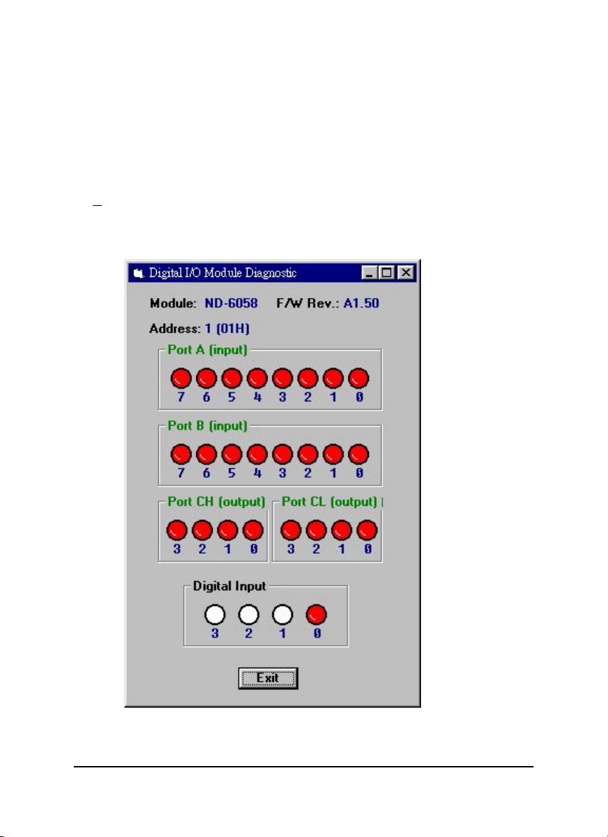
iag ICON for Operation-Diagnostic
This dialog is different by different-fuction modules.
Software Utility • 85
Page 90

Cal ICON for Operation-Calibration
This dialog is different by different-fuction modules.
86 • Software Utility
Page 91

6.3.4 Save and Print Nudam modules’ information
File-Save : Save all exist NuDAM modules information as display as in the
listbox in the current RS-485 network.
File-Print : Print the NuDAM module information in the listbox.
File-Exit : Quit the NuDAM Administration Utility.
Software Utility • 87
Page 92

6.3.5 Version Information
Help-About Version information
88 • Software Utility
Page 93

Troubleshooting and
Maintenance
Preventive Maintain
z Periodic check for loose connection
ATTENTION: To avoid electircal shock or unintended operation of the
module, remove incoming power before checking connections.
Using the LED Indication
The LED provides status information on Modules operation. The
troubleshooting about shows LED indicator. It also shows how to use the LED to
detect and correct common operating problems.
LED What it Means: What to do:
OFF Module is not receiving input
power by loosing wiring.
ON(RED) Normal receiving state. No action required.
Flashing Normal transmitting state. No action required.
Other Malfunctions
Problem What it Means: What to do:
Check module wiring,
cable connections, and
cable connections on
terminal block.
Do not
function
Loose wiring
Incorrect DIP switch setting
Check wiring and cable
connection
Check Baudrate and data
packet setting of the DIP
switch.
Troubleshooting and Maintenance • 89
Page 94

Warranty Policy
Thank you for choosing ADLINK. To understand your rights and enjoy all the
after-sales services we offer, please read the following carefully.
1. Before using ADLINK’s products please read the user manual and
follow the instructions exactly. When sending in damaged products for
repair, please attach an RMA application form which can be
downloaded from: http://rma.adlinktech.com/policy/.
2. All ADLINK products come with a limited two-year warranty, one year
for products bought in China.
• The warranty period starts on the day the product is shipped from
ADLINK’s factory.
• Peripherals and third-party products not manufactured by ADLINK
will be covered by the original manufacturers' warranty.
• For products containing storage devices (hard drives, flash cards,
etc.), please back up your data before sending them for repair.
ADLINK is not responsible for any loss of data.
• Please ensure the use of properly licensed software with our
systems. ADLINK does not condone the use of pirated software
and will not service systems using such software. ADLINK will not
be held legally responsible for products shipped with unlicensed
software installed by the user.
• For general repairs, please do not include peripheral accessories.
If peripherals need to be included, be certain to specify which
items you sent on the RMA Request & Confirmation Form.
ADLINK is not responsible for items not listed on the RMA
Request & Confirmation Form.
3. Our repair service is not covered by ADLINK's guarantee in the
following situations:
• Damage caused by not following instructions in the User's Manual.
• Damage caused by carelessness on the user's part during product
transportation.
• Damage caused by fire, earthquakes, floods, lightening, pollution,
other acts of God, and/or incorrect usage of voltage transformers.
90 • Warranty Policy
Page 95

• Damage caused by inappropriate storage environments such as
with high temperatures, high humidity, or volatile chemicals.
• Damage caused by leakage of battery fluid during or after change
of batteries by customer/user.
• Damage from improper repair by unauthorized ADLINK
technicians.
• Products with altered and/or damaged serial numbers are not
entitled to our service.
• This warranty is not transferable or extendible.
• Other categories not protected under our warranty.
4. Customers are responsible for all fees necessary to transport damaged
products to ADLINK.
For further questions, please e-mail our FAE staff: service@adlinktech.com
Warranty Policy •
 Loading...