

Page 1

ND-6021 & ND-6024
Analog Input Modules
User’s Guide
Page 2

Page 3

©Copyright 1996~2001 ADLINK Technology Inc.
All Rights Reserved.
Manual Rev. 4.00: June 5,2001
The information in this document is subject to change without prior notice in
order to improve reliability, design and function and does not represent a
commitment on the part of the manufacturer.
In no event will the manufacturer be liable to direct, indirect, special, incidental,
or consequential damages arising out of the use or inability to use the product
or documentation, even if advised of the possibility of such damages.
This document contains proprietary information protected by copyright. All
rights are reserved. No part of this manual may be reproduced by any
mechanical, electronic, or other means in any form without prior written
permission of the manufacturer.
Trademarks
NuDAM
Other product names mentioned herein are used for identification purposes
only and may be trademarks and/or registered trademarks of their respective
companies.
is registered trademarks of ADLINK Technology Inc.,
Page 4

Page 5

Table of Contents
Chapter 1 Introduction .......................................................1
1.1 About the NuDAM Analog Output Modules ............................. 1
1.2 Overview of NuDAM-6021 ....................................................... 2
1.3 Overview of NuDAM-6024 ....................................................... 7
Chapter 2 Initialization & Installation ..............................12
2.1 Software Installation............................................................... 12
2.2 Initializing a Brand-New Module............................................. 13
2.3 Install a New NuDAM to a Existing Network .......................... 15
2.4 Application Wiring for NuDAM-6021 ......................................16
2.5 Application Wiring for NuDAM-6024 ......................................17
Chapter 3 Command Set .................................................. 18
3.1 Command and Response ...................................................... 18
3.2 Summary of Command Set.................................................... 21
3.2. Set Configuration.................................................................... 23
3.3 Read Configuration ................................................................26
3.4 Read Module Name ...............................................................27
3.5 Read Firmware Version.......................................................... 28
3.6 Reset Status........................................................................... 29
3.7 Synchronized Sampling (6024 only) ......................................30
3.8 Read Synchronized Data (6024 only) .................................... 31
3.9 Digital Input (6024 only) .........................................................32
3.10 Analog Data Output................................................................ 33
3.11 4mA Offset Calibration ........................................................... 35
3.12 20mA Calibration.................................................................... 36
3.13 Trim Calibration ...................................................................... 37
3.14 Save Power On Analog Output Value.................................... 38
3.15 Last Value Readback ............................................................. 39
3.16 Current Readback .................................................................. 40
3.17 Read....................................................................................... 41
3.18 Change Leading Code Setting ............................................... 43
3.19 Set Host Watchdog Timer & Safety Value ............................. 45
3.20 Read Host Watchdog Timer & Safety Value.......................... 48
3.21 Host is OK .............................................................................. 50
Table of Contents • i
Page 6

Chapter 4 Data Format .....................................................51
4.1 Unit Conversion...................................................................... 51
4.2 Engineering Units................................................................... 52
4.3 Percent of FSR....................................................................... 53
4.4 Hexdecimal Format ................................................................ 54
4.5 Summary of Data Format....................................................... 55
Chapter 5 Analog Output Calibration.............................. 56
5.1 Calibration .............................................................................. 56
5.2 Analog Output Module Calibration ......................................... 56
Product Warranty/Service ...... Error! Bookmark not defined.
ii • Table of Contents
Page 7

1
Introduction
1.1 About the NuDAM Analog Output Modules
The NuDAM provides an analog output modules which can convert the digital
command to analog. The basic features of each module are shown here.
• NuDAM-6021 : analog signal output module with safety functions
• NuDAM-6024 : 4 channel analog output module
Introduction • 1
Page 8

1.2 Overview of NuDAM-6021
What is NuDAM-6021 ?
ND-6021 is an analog signal output module. It receives the digital command
from host computer through RS-485 network. The format of the digital value
can be engineering units, hexdecimal format or percentage of full-scale
range(FSR). A microprocessor is used to convert the digital command to
digital value to send to DAC. The DAC converts the digital value into analog
form. The analog output can be either voltage or current output.
The ND-6021 is designed for safety. It provides many safety functions such as
isolation, watchdog, and power on safe value. The opto-isolators provide
5000Vrms isolation voltage to isolate the digital section and the remote
controlled analog equipments. The damage of power surges is avoided.
Another safety fucntion is the watchdog. Whenever the host is loss contact with
the remoted NuDAM module, or the micro-processor is down, the module will
reset itself and send the safety value to the analog output therefore the industry
safety is guarantee. The safety value / power-up value can be set by
configuration software.
The analog output can be readback through the module‘s ADC. which can
monitor the ’real‘ output of the device. The host can check the digital command
and the real output to avoid short circuits. The slew rate of the output signal is
also controllable by software.
Features of NuDAM-6021
• One uni-polar analog output channel
• Two sets of differential current and voltage output terminals
• Versatile digital signal format
• Programmable host watchdog timer for host failure protection
• Internal watchdog timer for device failure protection
• Easy programming by software
• Easy installation and wiring
2 • Introduction
Page 9

Specifications of NuDAM-6021
Interface
♦
• Interface : RS-485, 2 wires
• Speed (bps) : 1200, 2400, 4800, 9600, 19.2K, 38.4K
Analog Output
♦
• Singal Output type: Differential type
• Resolution: 12 bits
• Accuracy: ±0.1% of FSR for current output
±0.2% of FSR for voltage output
• Unit Convertion: V or mA
• Output range: Voltage output: 0 to 10 V (uni-polar)
Current output: 0 to 20 mA,4 to 20 mA
• Maximum Sampling Rate: 100 samples /sec
• Slew rate: Voltage output: 0.0625 to 64 V/sec
Current output: 0.125 to 128 mA/sec
• Internal Current Load Resistor: 500Ω (%1)
Readback Analog Input
♦
• Accuracy: ±0.2% of FSR
Isolation
♦
• Isolation voltage: 5000 Vrms
Watchdog Function
♦
• Module internal watchdog timer : 150 ms
• Power failure threshold : 4.65 V
• Host programmable watchdog : 100 ms ~ 25.500 sec
Introduction • 3
Page 10

Power
♦
• Power supply : +10V to +30V
• Power consumption : 1.0W
Pin Definitions of ND-6021
Pin # Signal Name Description
1 +IOUT Positive Current Output Terminal
2 -IOUT Negative Current OutputTerminal
3 +VOUT Positive Voltage Output Terminal
4 -VOUT Negative Voltage Output Terminal
6 Default* Initial state setting
7 (Y) DATA+ RS-485 series signal, positive
8 (G) DATA- RS-485 series signal, negative
9 (R) +Vs Power supply, +10V~+30V
10 (B) GND Ground
4 • Introduction
Page 11
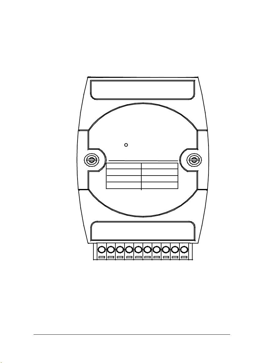
A Look at ND-6021 & Pin Assignment
20
Analog Output
ND-6021
Code Output R ange
30
31
32
(Current/Voltage)
0 ~20 mA
4 ~ 20 mA
0 ~ 10V
1
+VOUT
-IOUT
+IOUT
-VOUT
DEFAULT*
(Y)DATA+
(G)DATA-
11
10
(R)+Vs
(B)GND
Introduction • 5
Page 12
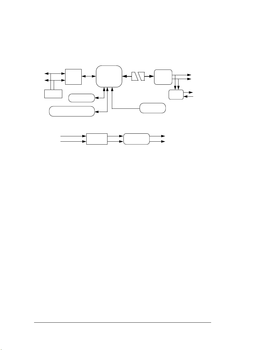
Functional Block Diagram of ND-6021
Data+
RS-485
Rec/DRv
Data-
RS-485
Terminator
Watchdog / Power Failure
Supervisor
+10V ~ +30 V
GND
EEPROM
Power
Regulator
Micro
Processor
+5V
GND
DC to DC
Convertor
Photo
Isolators
*Defalut Setting
(1 bit Digital In)
DAC
(12 bits)
Voltage Output
V to I
Current Output
Isolated Power
Isolated Ground
VOUT +
VOUT -
IOUT +
IOUT -
6 • Introduction
Page 13

1.3 Overview of NuDAM-6024
What is NuDAM-6024 ?
ND-6024 is a 4 channel bipolar analog signal output module. It receives the
digital command from host computer through RS-485 network. A
microprocessor is used to convert the digital command to digital value to send
to DAC. The DAC converts the digital value into analog form.
The ND-6024 is designed for safety. It provides many safety functions such as
isolation, watchdog, and power on safe value. The opto-isolators provide
5000Vrms isolation voltage to isolate the digital section and the remote
controlled analog equipments. The damage of power surges is avoided.
Another safety fucntion is the watchdog. Whenever the host is loss contact
with the remoted NuDAM module, or the micro-processor is down, the module
will reset itself and send the safety value to the analog output therefore the
industry safety is guarantee. The safety value / power-up value can be set by
configuration software.
Features of NuDAM-6024
• 4 channel bipolar analog output
• Programmable host watchdog timer for host failure protection
• Internal watchdog timer for device failure protection
• Easy programming by software
• Easy installation and wiring
Specifications of NuDAM-6024
Interface
♦
• Interface : RS-485, 2 wires
• Speed (bps) : 1200, 2400, 4800, 9600, 19.2K, 38.4K
Analog Output
♦
• Channel numbers : 4
• Singal Output type: Differential output
Introduction • 7
Page 14

Voltage Output: ±10V
♦
• Resolution: 12-bit resolution
• Accuracy: ±1/2 LSB
• Gain Drift: ±5ppm/°C
Digital Input
♦
• Channel numbers : 7
• Logical level 0: +2V max.
Logical Level 1: +3.5V ~ +30V
Isolation
♦
• Isolation voltage: 5000 Vrms
Watchdog Function
♦
• Module internal watchdog timer : 150 ms
• Power failure threshold : 4.65 V
• Host programmable watchdog : 100 ms ~ 25.500 sec
Power
♦
• Power supply : +10V to +30V
• Power consumption : 2.5W
8 • Introduction
Page 15

Pin Definitions of ND-6024
Pin # Signal Name Description
1 DI4 Digital input channel 4
2 DI3 Digital input channel 3
3 DI2 Digital input channel 2
4 DI1 Digital input channel 1
5 DI0 Digital input channel 0
6 Default* Initial state setting
7 (Y) DATA+ RS-485 series signal, positive
8 (G) DATA- RS-485 series signal, negative
9 (R) +Vs Power supply, +10V~+30V
10 (B) GND Ground
11 VOUTA+ Positive Voltage Output A Terminal
12 AGND Negative Voltage Output A Terminal
13 VOUTB+ Positive Voltage Output B Terminal
14 BGND Negative Voltage Output B Terminal
15 VOUTC+ Positive Voltage Output C Terminal
16 CGND Negative Voltage Output C Terminal
17 VOUTD+ Positive Voltage Output D Terminal
18 DGND Negative Voltage Output D Terminal
19 DI6 Digital input channel 6
20 DI5 Digital input channel 5
Introduction • 9
Page 16
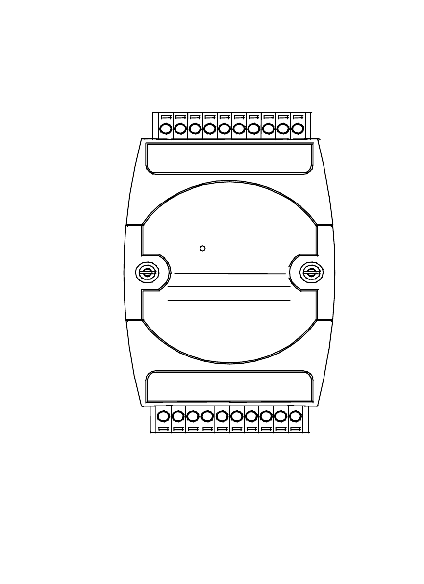
A Look at ND-6024 & Pin Assignment
DI5
DI6
DGND
VOU TD+
ND-6024 4-CH
Code Signal
33
CGND
VOU TC+
BGND
VOU TB +
Analog Output
10V
±
AGND
VOU TA+
10 • Introduction
DI4
DI3
DI2
DI1
DI0
DEFAULT*
(Y)DATA+
(G)DATA-
(R)+Vs
(B)GND
Page 17
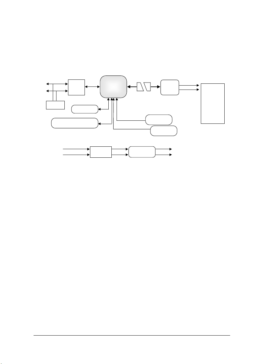
Functional Block Diagram of ND-6024
Data+
RS-485
Rec/DRv
Data-
RS-485
Terminator
Watchdog / Power Failure
Supervisor
+10V ~ +30 V
GND
EEPROM
Power
Regulator
Micro
Processor
+5V
GND
DC to DC
Convertor
Photo
Isolators
*Defalut Setting
(1 bit Digital In)
DAC
(12 bits)
DIØ…… DI6
Voltage Outpu t
Isolated Pow er
Isolated Grou nd
•VOUTA+
AGND
•VOUTB+
BGND
•VOUTC+
CGND
•VOUTD+
DGND
Introduction • 11
Page 18

2
Initialization & Installation
2.1 Software Installation
1. If you have already installed “NuDAM Administration” then skip other
steps.
2. Backup your software diskette.
3. Insert “NuDAM Administration” diskette into floppy drive A:
4. Change drive to A:
5. Installation command syntax
INSTALL drive:
drive name is C to Z.
Example 1 : install to drive C:
A:\>
Example 2 : install to drive F:
A:\>
6. NuDAM Administration Utility will be installed in the directory C:\NUDAM
12 • Initialization & Installation
INSTALL C:
INSTALL F:
Page 19

2.2 Initializing a Brand-New Module
Objective of Initializing a Brand-New NuDAM
All NuDAM modules, except NuDAM-6520 and NuDAM-6510, in a RS-485
network must have an unique address ID. Every brand-new NuDAM has a
factory default setting as following:
• Address ID is 01
• Baud rate is 9600 bps
• Check-sum disable
• Host Watchdog timer is disable
Therefore, to configure the brand-new NuDAM before using is necessary to
avoid conflicting address. The baud rate may also be changed according to
user‘s requirements.
The initialization procedures of a brand-new NuDAM are shown in the following
sections.
Default State
The NuDAM modules must be set at Default State when you want to change the
default settings, including the ID address, baud rate, check-sum status etc. All
NuDAM modules have an special pin labeled as
be in Default State if the
Under this state, the default configuration is set as following:
DEFAULT*
pin is shorted to ground when power ON.
DEFAULT*
. The module will
• Address ID is 00
• Baud rate is 9600 bps
• Check-sum disable
• Watchdog timer is disable
Therefore, the configuration of the host and the module can be easily set
identically and initializing a module will be possible no matter what configuration
is set under operating state.
Initialization Equipments
• Host computer with an RS-232 port
• An installed RS-485 module (NuDAM-6520) with 9600 baud rate
• The brand new NuDAM module
Initialization & Installation • 13
Page 20
• Power supply (+10 to +30 VDC) for NuDAM modules
• Administrating utility software
Initialization Procedure
1. Power off the host computer and the installed NuDAM-6520. Be sure of
the baud rate of the NuDAM-6520 is 9600 bps.
2. Connect a brand new NuDAM module with the RS-485. Set the module
in Default State by shorting the
detailed wiring.
3. Power on the host computer.
4. Power on the power supply for NuDAM modules.
5. Use the NuDAM Administrating utility to configure the address ID, Baud
rate and check-sum status of the module.
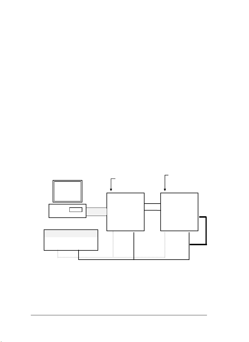
Initialization Wiring
DEFAULT*
pin. Refer to Figure 2.1 for
Host
Computer
RS-232
Local Power Supply
+10 V to +30 V
+Vs GND
Figure 2-1 Layout for Initialization the NuDAM module
14 • Initialization & Installation
NuDAM-6520
RS-232/RS-485
Converter
DATA +
DATA -
+Vs GND
New
NuDAM
module
DATA+
DATA Default*
+Vs GND
Page 21

2.3 Install a New NuDAM to a Existing Network
Equipments for Install a New Module
• A existing NuDAM network
• New NuDAM modules
• Power supply (+10 to +30 V
Installing Procedures
1. Configure the new NuDAM module according to the initialization
procedure in section 2.2.
2. The baud rate and check-sum status of the new module must be identity
with the existing RS-485 network. The address ID must not be conflict
with other NuDAM modules on the network.
3. Power off the NuDAM power supply of the existing RS-485 network.
4. Power off the host computer.
5. Wire the power lines for the new NuDAM with the existing network. Be
careful about the signal polarity as wiring.
6. Wire the RS-485 data lines for the new NuDAM with the existing
network. Be careful about the signal polarity as wiring.
7. Wire to the input or output devices. Refer to section 2.4 for illustrations.
8. Power on the host computer.
9. Power on the NuDAM local power supply.
DC
)
10. Use the NuDAM administration utility to check entire network.
Initialization & Installation • 15
Page 22

2.4 Application Wiring for NuDAM-6021
Differential Current Output
Differential Current Output Channel of NuDAM 6021
DAC
Differential Voltage Output
Differential Voltage Output Channel of NuDAM 6021
DAC
+IOUT
Current Loading
-IOUT
+VOUT
Voltage Loading
-VOUT
16 • Initialization & Installation
Page 23

2.5 Application Wiring for NuDAM-6024
Differential Voltage Output
Differential Voltage Output Channel of NuDAM 6021
DAC
+VOUT
Voltage Loading
-VOUT
Initialization & Installation • 17
Page 24

3
Command Set
3.1 Command and Response
Introduction
The NuDAM command is composed by numbers of characteristics, including
the leading code, address ID, the variables, the optional check-sum bytes, and
a carriage return to indicate the end of a command. The host computer can
only command only one NuDAM module except those synchronized
commands with wildcard address “**”. The NuDAM may or may not give
response to the command. The host should check the response to handshake
with the modules.
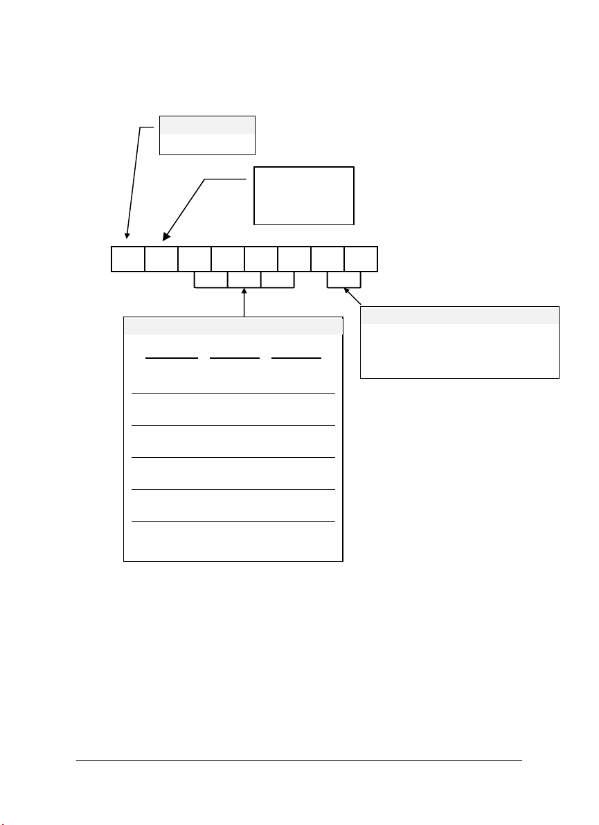
Document Conventions
The following syntax conventions describes the NuDAM commands in this
manual.
Leading Code is the first characteristic of the NuDAM
(Leading Code)
(Addr)
(Command
Variable)
[Data]
[Checksum]
command. All NuDAM commands need a command
leading code, such as %,$,#,@,...etc.
1- character
Module’s address ID, the value is in the range of 00 - FF
(Hex).
2- character
Command codes or value of variables.
Variable length
Some commands need additional data.
Variable length
Checksum in brackets indicate optional parameter,
only checksum is enable then this field is required.
18 • Command Set
Page 25

2- character
< >
Format of NuDAM Commands
(Leading Code)(Addr)(Command)[Data][Checksum]<CR>
When checksum is enable then [Checksum] is needed, it is 2-character. Both
command and response must append the checksum characters.
How to calculate checksum value ?
Identifies a control code character, such as <CR> for
carriage return, its value is 0x0D. 1- character
[Checksum] =
Example 1: checksum is disable
Example 2: checksum is enable
‘$’ = 0x24 ‘0’ = 0x30 ‘1’ = 0x31 ‘2’ = 0x32
((LeadingCode)+(Addr)+(Command)+[Data])
User Command : $012<CR>
Response : !01400600<CR>
$
01
2
<CR>
User Command :
Response :
$
01
2
B7
<CR>
: LeadingCode
: Address
: Command (Read Configuration)
: Carriage return 0x0D
$012B7<CR>
!01400600AC<CR>
: LeadingCode
: Address
: Command (Read Configuration)
: Checksum value
: Carriage return 0x0D
MOD 0x100
Command Set • 19
Page 26

B7 = (
0x24 + 0x30 + 0x31 + 0x32
‘!’ = 0x24 ‘0’ = 0x30 ‘1’ = 0x31 ‘4’ = 0x34
‘6’ = 0x36
AC
= ( 0x24 + 0x30 + 0x31 + 0x34 + 0x30 + 0x30 + 0x36 + 0x30
MOD 0x100
Note : 1. There is no spacing between the command words and the
2. Every command follows a <CR> carriage return for ending.
3. The checksum characters are optional.
Response of NuDAM Commands
The response message depends on versatile NuDAM command. The
response is composed with a few characteristics, including leading code,
variables, and carriage return for ending. There are two categories of leading
code for response message, ”!“ or ”>“ means valid command and ”?“ means
invalid. By checking the response message, user can monitor the command is
valid or not.
Note : Under the following conditions, there will have no response message.
1. The specified address ID is not exist.
2. Syntax error.
3. Communication error.
4. Some special commands does not have response message .
checksum characters.
) MOD 0x100
)
20 • Command Set
Page 27

3.2 Summary of Command Set
There are three categories of NuDAM commands. The first is the general
commands, including set configuration command, read configuration, reset,
read module‘s name or firmware version, etc. Every NuDAM can response to
the general commands. The second is the functional commands, which
depends on functions of each module. Not every module can execute all
function commands. The third is the special commands including functions
about the programmable watchdog timer, safe values, and the programmable
leading code. All the commands used in the NuDAM analog output module are
list in the following table.
Command Set of Analog Output Modules
Command Syntax Module
s
General Commands
Set Configuration
Read Configuration
Read Module Name
Read Firmware Version
Reset Status
Functional Commands
Synchronized Sampling
Read Synchronized Data
Digital Input
Analog Data Out
4 mA Offset Calibration
20 mA Offset Calibration
Trim Calibration
Save Power On Analog
Value
Last Value Readback
Current Readback
Special Commands
Read Command Leading
Code Setting
Change Command
%(OldAddr)(NewAddr)
All 23
(OutputRange)(BaudRate)
(DataFormat)
$(Addr)2
$(Addr)M
$(Addr)F
$(Addr)5
#**
$(Addr)9
$(Addr)8
#(Addr)(OutData)
#(Addr)(Port)(OutData)
All 26
All 27
All 28
All 29
6024
6024
6024
6021 30
6024
$(Addr)0 6021(1)
$(Addr)1 6021(1)
$(Addr)3(Counts) All(1)
$(Addr)4
$(Addr)6
$(Addr)6(Port)
$(Addr)8
~(Addr)0
~(Addr)10(C1)(C2)(C3)
All 38
6021 39
6024
6021 40
All
All 43
Error!
Bookmark
not
defined.
Page
35
36
37
Command Set • 21
Page 28

Leading Code Setting
Set Host Watchdog /
Safety Value
Read Host WatchDog /
Safe Value
Host is OK
Note: “ALL” means for ND-6021, ND-6024
(1) For Firmware Reversion E1.00,the command must beprocessed in
*Default mode.
(C4)(C5)(C6)
~(Addr)2(Flag)(TimeOut)
(SafeValue)
~(Addr)2(Flag)(TimeOut)
(SafeA)(SafeB)(SafeC)
(SafeD)
~(Addr)3
~**
6021 45
6024
All 48
All 50
22 • Command Set
Page 29

3.2. Set Configuration
@Description
Configure the basic setting of NuDAM, including the address ID, output
signal range, baud rate, and data format. The new configuration will be
available after executing the command.
@Syntax
%(OldAddr)(NewAddr)(OutputRange)(BaudRate)(DataFormat)<CR>
% Command leading code. (1-character)
NuDAM module original address ID. The
(OldAddr)
(NewAddr)
(OutputRange)
(BaudRate)
(DataFormat)
default address ID of a brand new module is
01. The value range of address ID is 00 to FF
in hexadecimal. (2-character)
New address ID, if you don’t want to change
address ID, let new address ID equals to the
old one. (2-character)
Define analog output range, refers to Table
3-1 for details. (2-character)
Define communication baud rate, refers to
Table 3-2 for details. (2-character)
Define checksum, integration time and
output data format, refers to Figure 3-1 for
details. (2-character)
@Response
!(Addr)<CR>
or
?(Addr)<CR>
(Addr)
!
?
Note : When you want to change the checksum or baud rate, the DEFAULT*
pin must be grounded at first.
@Example
Address ID.
Command is valid.
Command is invalid, parameter values are invalid,
or change the setting without grounding the
DEFAULT* pin.
Command Set • 23
Page 30

User command: %0118310610<CR>
Response: !18<CR>
Item Meaning Description
% (Leading Code) Command leading code.
01 (OldAddr) Original address ID is 01(Hex).
18 (NewAddr) New address ID is 18(Hex).
31 (OutputRange) Analog output range is 4 to 20 mA
06 (BaudRate) Baud rate is 9600.
10 (DataFormat) 10 means a slew rate is 1.000 mA/sec
and checksum is disable.
<CR> Carriage return 0x0D.
Code
(Hex)
30 0 to 20 mA 6021
31 4 to 20 mA 6021
32 0 to 10 V 6021
33 -10 to 10 V 6024
Signal Range of Output Range Modules
Table 0-1 Analog Output Range Setting
Code Baudrate
03 1200 bps
04 2400 bps
05 4800 bps
06 9600 bps
07 19200 bps
08 38400 bps
24 • Command Set
Table 3-2 Baud rate setting code
Page 31
Reserved
Must to be 0
Checksum
0 : disable
1 : enable
7
6 5
BitCode
0000 immediate change
0001 0.0625
4
3
2 1 0
Slew Rate
Voltage Current
V/sec 0.125 mA/sec
Analog Output Data Unit
00 : Engineering units
01 : % of Full Scale Range
10 : Hexadecimal
0010 0.125 V/sec 0.250 mA/sec
0011 0.250
V/sec 0.500 mA/sec
0100 0.500 V/sec 1.000 mA/sec
0101 1.000 V/sec 2.000 mA/sec
0110 2.000
V/sec 4.000 mA/sec
0111 4.000 V/sec 8.000 mA/sec
1000 8.000 V/sec 16.00 mA/sec
1001 16.00
V/sec 32.00 mA/sec
1010 32.00 V/sec 64.00 mA/sec
1011 64.00 V/sec 128.0 mA/sec
Figure 3-1 Data format of Analog Output Setting
*6024 only supports immediate change and engineering units.
Command Set • 25
Page 32

3.3 Read Configuration
@Description
Read the configuration of module on a specified address ID.
@Syntax
$(Addr)2<CR>
$
(Addr)
2
@Response
!(Addr)(OutputRange)(BaudRate)(DataFormat)<CR>
or
?(Addr)<CR>
!
?
(Addr)
(OutputRange)
(BaudRate)
(DataFormat)
@Example
User command: $182<CR>
Response: !18320610<CR>
!
18
32
06
10
Command leading code
Address ID.
Command code for reading configuration
Command is valid.
Command is invalid.
Address ID.
Current setting of analog voltage output, refers
to Table 3-1 for details.
Current setting of communication baud rate,
refers to Table 3-2 for details.
Current settings of checksum, integration time
and output data format, refers to Figure 3-1 for
details.
Command is valid.
Address ID.
Analog output range is 0 to 10V
Baud rate is 9600 bps.
The output data is in engineering units, slew rate is
1mA/sec, checksum is disable.
26 • Command Set
Page 33

3.4 Read Module Name
@Description
Read module name of NuDAM at specified address.
@Syntax
$(Addr)M<CR>
$
(Addr)
M
@Response
!(Addr)(ModuleName) <CR>
or
?(Addr)<CR>
!
?
(Addr)
(ModuleName)
@Example
User command: $18M<CR>
Response: !186021<CR>
!
18
6021
Command leading code.
Address ID.
Read module name.
Command is valid.
Command is invalid.
Address ID.
NuDAM module‘s name would be ’6021‘.
4 characters
Command is valid.
Address ID is 18 (Hex).
ND-6021 (It is a analog output module)
Command Set • 27
Page 34

3.5 Read Firmware Version
@Description
Read firmware version of NuDAM at specified address.
@Syntax
$(Addr)F<CR>
$
(Addr)
F
@Response
!(Addr)(FirmRev) <CR>
or
?(Addr)<CR>
!
?
(Addr)
(FirmRev)
@Example
User command: $18F<CR>
Response: !18A2.30<CR>
!
18
A2.30
Command leading code.
Address ID
Read module firmware version.
Command is valid.
Command is invalid.
Address ID.
NuDAM module‘s firmware version.
Command is valid.
Address ID is 18 (Hex).
Firmware Version
28 • Command Set
Page 35

3.6 Reset Status
@Description
Read the reset status of module at specified address to check whether if it
has been reset since the last reset status command was issued to the
module.
@Syntax
$(Addr)5<CR>
$
(Addr)
5
@Response
!(Addr)(Status)<CR>
or
?(Addr)<CR>
!
?
(Addr)
(Status)
@Example
User command: $185<CR>
Response: !180<CR>
Status is 0 means this digital I/O module has not been reset,
since the last reset status command was issued.
Command leading code.
Address ID.
Reset Status Command.
Command is valid.
Command is invalid.
Address ID.
0 : It has not been reset since the last reset
status command was issued.
1 : It has been reset since the last reset
status command was issued.
Command Set • 29
Page 36

3.7 Synchronized Sampling (6024 only)
@Description
Synchronized all modules to sample input values and stored the values in
the module’s register at the same time and use “Read Synchronized Data”
command to read the data and process it one by one.
For analog output module, this command is only available to modules
involving the digital input function, such as NuDAM-6024.
@Syntax
#**<CR>
#
**
@Response
Note : Synchronized sampling command has NO response.
@Example
Command leading code.
Synchronized sampling command
User command:
Synchronized sampling command
30 • Command Set
#**<CR>
has no response
.
Page 37

3.8 Read Synchronized Data (6024 only)
@Description
After a synchronized sampling command
input value that was stored in the addressed module’s register and use
same method to process other module‘s data one by one.
@Syntax
$(Addr)9<CR>
$
(Addr)
9
@Response
!(Status)(DataIn)<CR>
or
?(Addr)<CR>
>
?
(Status)
(DataIn) Value of digital input channel. (2-character).
@Examples
User command: $309<CR>
Response: >17F<CR>
>
1
7F
Command leading code.
Address ID.
Read synchronized data.
Command is valid.
Command is invalid.
0 : Data has been sent at least once before.
1 : Data has been sent for the first time since a
synchronized sampling command was
issued.(1-character)
Command is valid.
Data has not been sent before.
7F(01111111) means digital input channel
0,1,2,3,4,5,6 are HIGH.
#**
was issued, you can read the
Command Set • 31
Page 38

3.9 Digital Input (6024 only)
@Description
Read the digital input channel value.
@Syntax
$(Addr)8<CR>
$
(Addr)
8
@Response
!(DataIn)0000<CR>
or
?(Addr)<CR>
!
?
(DataIn) Value of digital input. (2-character)
@Example
User command: $308<CR>
Response: !320000<CR>
!
32
0000
Command leading code.
Address ID
Digital data input command.
Command is valid.
Command is invalid.
Command is valid.
32 (00110010) means digital output channel 1, 4, 5
are ON, channel 0, 2, 3, 6 are OFF.
No used
32 • Command Set
Page 39

3.10 Analog Data Output
@Description
Send a value to analog output module at specified address. The data
format of the value can be engineering unit, percent, or hexdecimal value,
which is set by configuration setting command.
(ND-6024 only supports engineering format.)
@Syntax
#(Addr)(OutData)<CR> (6021 Only)
#(Addr)(Port)(OutData)<CR> (6024 Only)
# Command leading code. (1-character)
(Addr) Address ID. (2-character)
(Port)
(OutData)
@Response
<CR>
or
?(Addr)<CR>
>
?
(Addr)
@Examples
User command: #0616.000<CR>
Response: ><CR>
A, B, C or D
Value of the analog output signal,. The unit of the
value can be engineering units, % of FSR, or
hexadecimal value. Refers to chapter 4 for details of
the data format.
Command is valid.
Command is invalid or no synchronized sampling
command was issued.
Address ID.
The command sets the analog output to be 16 mA at address 06H, if the
data format is configured as engineering units and 0~20mA output range.
User command: #08+020.00<CR>
Response: ><CR>
Command Set • 33
Page 40

The command sets the analog output to be 4 mA at address 08H, if the
data format is configured as % of FSR and 0~20mA output range.
4mA = 20mA x 20.00%
User command: #097FF<CR>
Response: ><CR>
The command sets the analog output to be 5 V at address 09H, if the data
format is configured as hexdecimal format and output range of 0~10V.
5 V = 7FF / FFF x 10V
User command: #08A-05.000<CR>
Response: ><CR>
The command sets the analog output port A to be –5 V at address 08H.
34 • Command Set
Page 41

3.11 4mA Offset Calibration
@Description
Stores the current output value as 4 mA reference at the specified analog
output module.(only 6021)
@Syntax
$(Addr)0<CR>
$
(Addr)
0
@Response
!(Addr)<CR>
or
?(Addr)<CR>
!
?
(Addr)
@Example
User command: $060<CR>
Response: !06<CR>
Command leading code
Address ID
Command Code
Command is valid.
Command is invalid or no synchronized sampling
command was issued.
Address ID.
To perform the 4 mA calibartion for analog output module at address 06H.
Note : Analog output module should be trimmed to the correct value by “Trim
Calibration” command before to execute “4 mA Calibration”. Refers
to Chapter 5 “Analog Output Calibration” for details.
Command Set • 35
Page 42

3.12 20mA Calibration
@Description
Stores the current output value as 20 mA reference at the specified analog
output module. (only 6021)
@Syntax
$(Addr)1<CR>
$
(Addr)
1
@Response
!(Addr)<CR>
or
?(Addr)<CR>
!
?
(Addr)
@Example
User command: $061<CR>
Response: !06<CR>
To perform the 20 mA calibration for analog input module at address ID
06H.
Note : Analog output module should be trimmed to the correct value by “Trim
Calibration” command before to execute “20 mA Calibration”. Refers
to Chapter 5 “Analog Output Calibration” for details .
Command leading code (1 character)
Address ID (2 characters)
Function Code, 20 mA calibration (1 character)
Command is valid.
Command is invalid.
Address ID.
36 • Command Set
Page 43

3.13 Trim Calibration
@Description
Trims the specified analog output module a specified number of units up or
down.
@Syntax
$(Addr)3(Counts)<CR>
$
(Addr)
3
(Counts)
@Response
!(Addr)<CR>
or
?(Addr)<CR>
!
?
(Addr)
@Example
User command: $06314<CR>
Response: !06<CR>
Increase analog output value about 97.6µA (14H * 4.88µA = 97.6µA) at
address 06H.
Command leading code
Address ID
Function Code
Number of counts to increase or decrease the output
current.
Range 00 - 5F : 0 to +95 counts (increase)
Range A1 - FF : -95 to -1 counts (decrease)
1 count equals approximately 4.88µA or 2.44mV
(4.88mV for ND-6024)
Command is valid.
Command is invalid.
Address ID.
Note : Analog output module trim calibration should have a corrent calibration
wiring. Refers to Chapter 5 “Analog Output Calibration” for details.
Command Set • 37
Page 44

3.14 Save Power On Analog Output Value
@Description
Save the current output value to the non-volatile register for NuDAM
analog output module. The power on value be put on the output channel
when system power ON.
@Syntax
$(Addr)4<CR>
$ Command leading code. (1-character)
(Addr) Address ID. (2-character)
4
@Response
!(Addr)<CR>
or
?(Addr)<CR>
!
?
(Addr)
@Example
User command: $064<CR>
Response: !06<CR>
Save the current analog output value as the default value when the analog
output module start-up.
Function code of saving power on analog value.
(1-character)
Command is valid.
Command is invalid.
Address ID.
38 • Command Set
Page 45

3.15 Last Value Readback
@Description
Return the latest analog output value which is set by “Analog Data Out”
command. If the analog output module never execute the “Analog Data
Out” command then it return the start-up output value. (only 6021)
@Syntax
$(Addr)6<CR>
$(Addr)6(Port)<CR> (6024 Only)
$ Command leading code. (1-character)
(Addr) Address ID. (2-character)
6
(Port)
@Response
!(Addr)(Data)<CR>
or
Function code of last value readback.
(1-character)
Port A, B, C or D.
?(Addr)<CR>
!
?
(Addr)
(Data)
@Example
User command: $086<CR>
Response: !0802.000<CR>
This analog output module return the latest output value is 2.000 mA at
address 08H, if data format is engineering units and the signal range is
0~20mA.
Command is valid.
Command is invalid.
Address ID.
The current analog output value, the data format
depends on module configuration.
Command Set • 39
Page 46

3.16 Current Readback
@Description
Read the estimated current output value at the specified analog output
module.
@Syntax
$(Addr)8<CR>
$ Command leading code. (1-character)
(Addr) Address ID. (2-character)
6
@Response
!(Addr)(Data)<CR>
or
?(Addr)<CR>
!
?
(Addr)
(Data)
@Example
User command: $088<CR>
Response: !0802.000<CR>
This analog output module return the latest output value is 2.000 mA at
address 08H, if data format is engineering units and the signal range is
0~20mA.
Function code of last value readback.
(1-character)
Command is valid.
Command is invalid.
Address ID.
The current analog output value, the data format
depends on module configuration.
40 • Command Set
Page 47

3.17 Read
@Description
Read command leading code setting and host watchdog status.
@Syntax
~(Addr)0<CR>
~
(Addr)
0
@Response
!(Addr)(Status)(C1)(C2)(C3)(C4)(C5)(C6)<CR>
or
?(Addr)<CR>
!
?
(Addr)
(Status)
(C1)
(C2)
(C3)
(C4)
(C5)
(C6)
Command leading code.
Address ID
Read command leading code setting.
Command is valid.
Command is invalid.
Address ID.
(2-character)
Bit 0 : Reserved
Bit 1 : Power failure or watchdog failure
Bit 2 : Host watchdog is enable
Bit 3 : Host failure
Leading code 1, for read configuration status,
firmware version, etc. default is $. (1-character)
Leading code 2, for read synchronize sampling,
digital output ,default is #. (1-character)
Leading code 3, for change configuration.
default is %. (1-character)
Leading code 4, for read alarm status, enable alarm,
etc. default is @. (1-character)
Leading code 5, for read command leading code,
change command leading code, etc. default is ~.
(1-character)
Leading code 6, this leading code is reserved. default
is *. (1-character)
Command Set • 41
Page 48

@Example
User command: ~060<CR>
Response: !0600$#%@~*<CR>
Command leading code setting is $#%@~* for module address ID is 06,
current status is factory default setting.
42 • Command Set
Page 49

3.18 Change Leading Code Setting
@Description
User can use this command to change command leading code setting as
he desired.
@Syntax
~(Addr)10(C1)(C2)(C3)(C4)(C5)(C6)<CR>
~
(Addr)
10
(C1)
(C2)
(C3)
(C4)
(C5)
(C6)
@Response
!(Addr)< CR>
or
?(Addr)<CR>
!
?
(Addr)
Command leading code.
Address ID, range (00 - FF).
Change command leading code setting.
Leading code 1, for read configuration status,
firmware version, etc. default is $.
(1-character)
Leading code 2, for read synchronize sampling,
digital output ,default is #. (1-character)
Leading code 3, for change configuration.
default is %. (1-character)
Leading code 4, for read alarm status, enable alarm,
etc. default is @. (1-character)
Leading code 5, for read command leading code,
change leading code, etc. default is ~.
(1-character)
Leading code 6, this leading code is reserved. default
is *. (1-character)
Command is valid.
Command is invalid.
Address ID.
Command Set • 43
Page 50

@Examples
User command: ~060<CR>
Response:
User command:
Response: !06<CR>
User command:
Response: !06A1.8<CR>
Read leading code setting is $#%@~* for module address 06 and change
leading code $ to A, then use A06F to read firmware version of module on
address 06.
*** WARNING ***
• We do not recommend users to change the default setting of leading
code, because it will confuse yourself.
• The leading code change only use the command conflicts other
devices of other brand on the network.
• The changing of leading code is not necessay if all modules in a
network are NuDAMs‘.
!0600$#%@~*<CR>
~0610A#%@~*<CR>
A06F
44 • Command Set
Page 51

3.19 Set Host Watchdog Timer & Safety Value
@Description
Set host watchdog timer, module will change to safety state when host is
failure. Define the output value in this command.
@Syntax
~(Addr)2(Flag)(TimeOut)(SafeValue)<CR>
~(Addr)2(Flag)(TimeOut)(SafeA)(SafeB)(SafeC)(SafeD) (6024 Only)
~
(Addr)
2
(Flag)
(TimeOut)
Command leading code.
Address ID, range (00 - FF).
Set host watchdog timer and safe state value.
0 : Disable host watchdog timer
1 : Enable host watchdog timer (1-character)
Host timeout value, between this time period host
must send (Host is OK) command to module,
otherwise module will change to safety state.
Range 01 - FF. (2-character)
One unit is 53.3 ms (Firmware version 1.x)
01 = 1 * 53.3 = 53.3 ms
FF = 255 * 53.3 = 13.6 sec
One unit is 100 ms (Firmware version 2.x)
01 = 1 * 100 = 100 ms
FF = 255 * 100 = 25.5 sec
(SafeValue)
(SafeA)
(SafeB)
(SafeC)
(SafeD)
Safety value of analog output when host is failure.
(3-character)
000: analog output is 0mA or 0 V
7FF: analog output is 10 mA or 5V
FFF: analog output is 20 mA or 10V
Safety value of analog output for port A, B, C and D
when host is failure. (3-character)
000: analog output is –10 V
800: analog output is 0 V
FFF: analog output is 10 V
Command Set • 45
Page 52

@Response
!(Addr)<CR>
or
?(Addr)<CR>
!
?
(Addr)
@Example
User command: ~0621123F0<CR>
Response: !06<CR>
06
2
1
12
3F0
Command is valid.
Command is invalid.
Address ID
Address ID
Set host watchdog timer and safe state value.
Enable host watchdog timer.
Timeout value. 0x12 = 18
18 * 53.3 = 959 ms (Firmware Version 1.x)
18 * 100 = 1800 ms (Firmware Version 2.x)
0x3F0 is hexadecimal
Analog output value is 4.923 mA for 0-20mA
Analog output value is 4.923 mA for 4-20mA
Analog output value is 2.462 V for 0-10 V
Analog output safety value are as following :
For type is 0 ~20 mA or 4~20 mA (Output Range is 0x30, 0x31)
value = (0x3F0 / 0xFFF) * 20 mA = 4.923 mA
For type is 0 ~10V (Output Range is 0x32)
value = (0x3F0 / 0xFFF) * 10 V = 2.462 V
User command: ~062112800800800800<CR>
Response: !06<CR>
46 • Command Set
Page 53

06
2
1
12
800
800
800
800
Address ID
Set host watchdog timer and safe state value.
Enable host watchdog timer.
Timeout value. 0x12 = 18
18 * 53.3 = 959 ms (Firmware Version 1.x)
18 * 100 = 1800 ms (Firmware Version 2.x)
0x800 is hexadecimal
Analog output value is 0V for port A
Analog output value is 0V for port B
Analog output value is 0V for port C
Analog output value is 0V for port D
Command Set • 47
Page 54

3.20 Read Host Watchdog Timer & Safety Value
@Description
Read host watchdog timer setting and the safety value.
@Syntax
~(Addr)3<CR>
~
(Addr)
3
@Response
!(Addr)(Flag)(TimeOut)(SafeValue)<CR>
!(Addr)(Flag)(TimeOut)(SafeA)(SafeB)(SafeC)(SafeD)<CR>(6024Only)
or
?(Addr)<CR>
!
?
(Addr)
(Flag)
(TimeOut)
Command leading code.
Address ID
Read host watchdog setting and module safety state
value.
Command is valid.
Command is invalid.
Address ID, range (00 - FF).
0 : Host watchdog timer is disable
1 : Host watchdog timer is enable(1-character)
Host timeout value.
Range 01 - FF. (2-character)
One unit is 53.3 ms (Firmware version 1.x)
01 = 1 * 53.3 = 53.3 ms
FF = 255 * 53.3 = 13.6 sec
One unit is 100 ms (Firmware version 2.x)
01 = 1 * 100 = 100 ms
FF = 255 * 100 = 25.5 sec
(SafeValue)
(SafeA)
(SafeB)
(SafeC)
48 • Command Set
Safety value of analog output when host is failure.
(3-character)
Safety value of analog output for port A, B, C and D
when host is failure. (3-character)
Page 55

@Example
User command: ~063<CR>
Response: !061123F0<CR>
06
1
12
3F0
User command: ~063<CR>
Response: !06112800800800800<CR>
06
1
12
Address ID
Host watchdog timer is enable.
Timeout value. 0x12 = 18
18 * 53.3 = 959 ms (Firmware Version 1.x)
18 * 100 = 1800 ms (Firmware Version 2.x)
0x3F0 is hexadecimal
Analog output value is 4.923 mA for 0-20mA
Analog output value is 4.923 mA for 4-20mA
Analog output value is 2.462 V for 0-10 V
Address ID
Host watchdog timer is enable.
Timeout value. 0x12 = 18
18 * 53.3 = 959 ms (Firmware Version 1.x)
18 * 100 = 1800 ms (Firmware Version 2.x)
800
800
800
800
0x800 is hexadecimal
Analog output value is 0V for port A
Analog output value is 0V for port B
Analog output value is 0V for port C
Analog output value is 0V for port D
Command Set • 49
Page 56

3.21 Host is OK
@Description
When host watchdog timer is enable, host computer must send this
command to every module before timeout otherwise
timer enable”
Timeout value and safety state output value is defined in 3.14. “Set Host
Watchdog Timer & Safety Value”
@Syntax
module‘s output value will go to safety state output value.
“host watchdog
~**<CR>
@Response
Note : Host is OK command has NO response.
@Example
~
**
User command: ~**<CR>
Command leading code.
Host is OK.
50 • Command Set
Page 57

4
Data Format
4.1 Unit Conversion
The data value in the command of the analog output module is corresponding
to the amplitude of the physical analog signal. The user should understand the
data format to represent a analog signal by an ASCII string. The physical
meaning of a data depends on both the unit conversion and the value. The unit
conversion of the digits value can be configured by the setting configuration
command. Three types of unit conversion are used in analog output modules.
1. Engineering units.
2. Percent of FSR (Full Scale Range).
3. Hexdecimal.
Data Format • 51
Page 58

4.2 Engineering Units
The date is in engineering unit when the bit 1 and 0 of the configuration register
are ‘00’. The data string is composited by 6 characters. Because the output of
ND-6021 is unipolar, the value is always positive.
The meaning of the value depends on the output range setting too. When the
output range is set to 0~10V, the unit of the value is in ‘Volts’. When the output
range is set to 0~20mA or 4~20mA, the unit of the value is in ‘mA’.
• Set bit 1 and bit 0 of data format variable to “00” means the data is
represented in engineering units
• Data string is fixed length of 6 characters. The value is composed of
five decimal digits with a decimal fixed point
• Two digits present the integer part and three present the fraction
Example 4.2.1:
• If the output range is set as 0 to 20 mA
• The desired analog output value is +5.678 mA
The data value should be :
Example 4.2.2:
• If the output range is set as 0 to 10 V
• The desired analog output value is +2.345 V
The data value should be :
52 • Data Format
05.678<CR>
02.345<CR>
Page 59

4.3 Percent of FSR
The date is in percent of FSR(Full Scale Range) when the bit 1 and 0 of the
configuration register are ‘01’. The data string is composited by 6 characters.
Because the output of ND-6021 is unipolar, the value is always positive.
The value is unit-less and depends on the output range setting too.
• Set bit 1 and bit 0 of data format variable to “01” means the data is
represented in percent of FSR.
• Data string is fixed length of 6 characters. The value is composed of
five decimal digits with a decimal fixed point.
• Three digits present the integer part and two digits present the fraction
• Maximum resolution is 0.2%.
Example 4.3.1 :
• If the output range is set as 0 to 20 mA
• The desired analog output current is 10 mA
The data value should be :
10 mA / 20 mA = 50.00 %
Example 4.3.2 :
• If the output range is set as 4 to 20 mA
• The desired analog output current is 10 mA
The data value should be :
(10 mA - 4 mA ) / (20 mA - 4mA) = 37.50 %
050.00<CR>
037.50<CR>
Data Format • 53
Page 60

4.4 Hexdecimal Format
The data is in hexdecimal format as the bit 1 and 0 are set as ‘10’. The data
string length is 3 characters. It is equivilant to 12 binary bits. Because the
output of ND-6021 is unipolar, the maximum value of the digits is FFF(H) and
the minimum value of the digits is 000(H).
As the output range is set to 0~20mA, the value ‘FFF(H)’ represents 20mA and
‘000(H)’ represents 0mA. Similarily, as the output range is set to 4~20mA, the
value ‘FFF(H)’ represents 20mA and ‘000(H)’ represents 4mA.
Example 4.3.1 :
• If the output range is set as 0 to 20 mA
• The desired analog output current is 10 mA
Two’s complement hexdecimal :
7FF<CR>
54 • Data Format
Page 61

4.5 Summary of Data Format
The following table shows the relation between the output range setting with
the data format and the resolution.
Code
30 0 to 20 mA Eng. Units 20.000 00.000
31 4 to 20 mA Eng. Units 20.000 04.000
32 0 to 10 V Eng. Units 10.000 00.000 2.442 mV
Code
30 0 to 20 mA % of FSR 100.00 000.00
31 4 to 20 mA % of FSR 100.00 000.00
32 0 to 10 V % of FSR 100.00 000.00 2.442 mV
Code
30 0 to 20 mA Hexdecimal FFF 000
31 4 to 20 mA Hexdecimal FFF 000
32 0 to 10 V Hexdecimal FFF 000 2.442 mV
Output
Range
Output
Range
Output
Range
Data
Format
Data
Format
Data
Format
Maximum
Value
Maximum
Value
Maximum
Value
Minimum
Value
Minimum
Value
Minimum
Value
Output
Resolutio
n
4.88µA
4.88µA
Output
Resolution
4.88µA
4.88µA
Output
Resolution
4.88µA
4.88µA
Data Format • 55
Page 62

5
Analog Output Calibration
5.1 Calibration
The NuDAM analog output module needs to be calibrated. It has a factory
default calibration . User can use NuDAM Adminstration utility to do any type of
calibration.
5.2 Analog Output Module Calibration
What do you need to do calibration ?
1. One 5 1/2 digit multimeter.
2. A resistor 250 Ω (Accurary is 0.01 %).
3. NuDAM Aministration Utility.
Calibration Procedure
1. Select output range to 0 ~20 mA or 4~20 mA.
2. Put the resistor 250 Ω to the NuDAM-6021 (+ IOUT (Pin.1) and -IOUT
(Pin.2)).
3. Put 5 1/2 digit multimeter to measure + IOUT (Pin.1) and -IOUT (Pin.2)
.
56 • Analog Output Calibration
Page 63

4. Send the “
output value is
command is
5. Use “
output value to
6. Send “
module to complete the 4 mA calibration.
7. Send the “
output value is
command is
8. Use “
output value to
9. Send “
module to complete the 20 mA calibration.
Analog Data Output
4 mA
. For example if the address is 0x03 then the
#0304.000.
Trim calibration
4mA Calibration
Analog Data Output
$(Addr)3(Counts)” command to adjust until the
1 V (4 mA)
$(Addr)0” command to the analog output
20 mA
. For example if the address is 0x03 then the
#0320.000
Trim calibration
5 V (20 mA)
20mA Calibration
Calibration wiring of NuDAM-6021
-IOUT
+IOUT
$(Addr)3(Counts)” command to adjust until the
#(Addr)(OutData)” command with
.
#(Addr)(OutData)” command with
.
$(Addr)1” command to the analog output
250 Ohms
+
-
5 1/2 Digital Meter
Analog Output Calibration • 57
Page 64

Warranty Policy
Thank you for choosing ADLINK. To understand your rights and enjoy all the
after-sales services we offer, please read the following carefully.
1. Before using ADLINK’s products please read the user manual and follow
the instructions exactly. When sending in damaged products for repair,
please attach an RMA application form which can be downloaded from:
http://rma.adlinktech.com/policy/.
2. All ADLINK products come with a limited two-year warranty, one year for
products bought in China.
• The warranty period starts on the day the product is shipped from
ADLINK’s factory.
• Peripherals and third-party products not manufactured by ADLINK
will be covered by the original manufacturers' warranty.
• For products containing storage devices (hard drives, flash cards,
etc.), please back up your data before sending them for repair.
ADLINK is not responsible for any loss of data.
• Please ensure the use of properly licensed software with our
systems. ADLINK does not condone the use of pirated software and
will not service systems using such software. ADLINK will not be
held legally responsible for products shipped with unlicensed
software installed by the user.
• For general repairs, please do not include peripheral accessories. If
peripherals need to be included, be certain to specify which items
you sent on the RMA Request & Confirmation Form. ADLINK is not
responsible for items not listed on the RMA Request & Confirmation
Form.
3. Our repair service is not covered by ADLINK's guarantee in the following
situations:
• Damage caused by not following instructions in the User's Manual.
• Damage caused by carelessness on the user's part during product
transportation.
• Damage caused by fire, earthquakes, floods, lightening, pollution,
other acts of God, and/or incorrect usage of voltage transformers.
58 • Product Warranty/Service
Page 65

• Damage caused by inappropriate storage environments such as
with high temperatures, high humidity, or volatile chemicals.
• Damage caused by leakage of battery fluid during or after change of
batteries by customer/user.
• Damage from improper repair by unauthorized ADLINK technicians.
• Products with altered and/or damaged serial numbers are not
entitled to our service.
• This warranty is not transferable or extendible.
• Other categories not protected under our warranty.
4. Customers are responsible for all fees necessary to transport damaged
products to ADLINK.
For further questions, please e-mail our FAE staff: service@adlinktech.com
Product Warranty/Service • 59
 Loading...