

Page 1
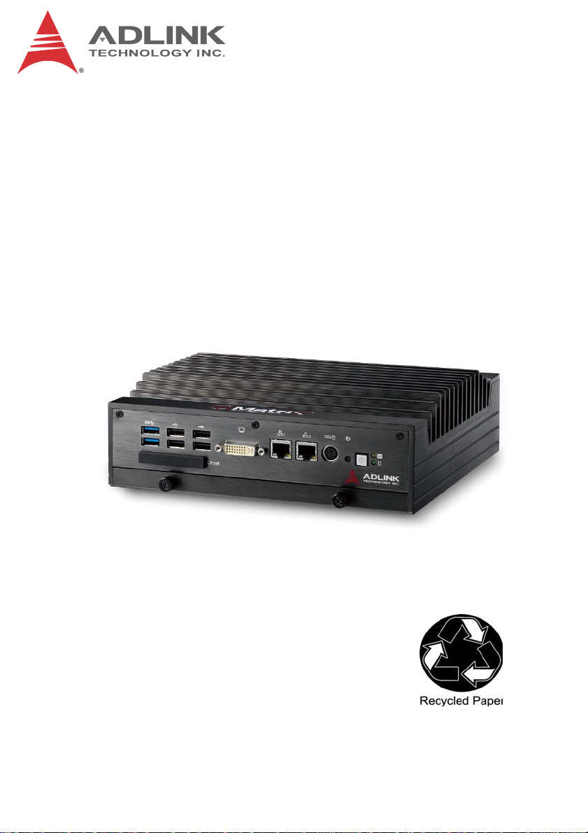
MXE-5300 Series
5301/5302/5303
Fanless Embedded Computer
User’s Manual
Manual Rev. 2.00
Revision Date: Dec. 23, 2011
Part No: 50-1Z112-2000
Advance Technologies; Automate the World.
Page 2

Revision History
Revision Release Date Description of Change(s)
2.00 Dec. 23, 2011 Initial release
ii
Page 3

MXE-5300
Table of Contents
Revision History...................................................................... ii
List of Tables......................................................................... vii
Preface.................................................................................... ix
1 Introduction ........................................................................ 1
1.1 Overview.............................................................................. 1
1.2 Features............................................................................... 2
1.3 Specifications....................................................................... 3
1.4 Unpacking Checklist ............................................................ 4
2 System Description............................................................ 7
2.1 Mechanical Views ................................................................ 7
2.2 Front Panel I/O Connectors ................................................. 9
2.2.1 LED Indicators ............................................................... 10
2.2.2 Power Switch ................................................................. 10
2.2.3 Reset Button .................................................................. 10
2.2.4 PS/2 Connector ............................................................. 10
2.2.5 Dual Gigabit Ethernet Ports ........................................... 11
2.2.6 DVI-I Connector ............................................................. 13
2.2.7 USB 2.0 Connectors ...................................................... 13
2.2.8 USB 3.0 Connectors ...................................................... 14
2.2.9 CFast Slot ...................................................................... 14
2.3 Rear Panel I/O Connectors................................................ 15
2.3.1 DC Power Supply Connector......................................... 15
2.3.2 Dual Gigabit Ethernet Ports ........................................... 16
2.3.3 eSATA Connector.......................................................... 17
2.3.4 Audio Jacks ................................................................... 17
2.3.5 DB-62P COM Port and Digital I/O Connector................ 18
2.4 Internal I/O Connectors...................................................... 21
iii
Page 4

MXE-5300
2.4.1 Clear CMOS and ME RTC Register Jumpers ............... 21
2.4.2 Mini-PCIe Connector ..................................................... 23
2.4.3 DC 5V and 3.3V Connectors for GPS Module............... 24
2.4.4 USIM Port ...................................................................... 24
2.4.5 SATA Connector............................................................ 24
3 Getting Started.................................................................. 25
3.1 Installing a Hard Disk Drive................................................ 25
3.2 Installing Memory............................................................... 29
3.3 Installing CFast Cards........................................................ 32
3.4 COM Ports and DIO Device............................................... 34
3.5 Connecting to DC power.................................................... 36
3.6 Wall-mounting the MXE-5300 ............................................ 37
3.7 Thermal Considerations..................................................... 40
4 Driver Installation.............................................................. 41
4.1 Installing the Chipset Driver ............................................... 41
4.2 Installing the Graphics Driver............................................. 42
4.3 Installing the Ethernet Driver.............................................. 42
4.4 Installing the Audio Driver.................................................. 43
4.5 Installing the WDT Driver ................................................... 43
5 BIOS Settings.................................................................... 45
5.1 Main ................................................................................... 46
5.1.1 BIOS Information ........................................................... 46
5.1.2 System Time/System Date ............................................ 46
5.2 Advanced ........................................................................... 47
5.2.1 ACPI Settings ................................................................ 48
5.2.2 CPU Configuration......................................................... 49
5.2.3 Onboard Device Configuration ...................................... 51
5.2.4 Advanced Power Management...................................... 52
5.2.5 SATA Configuration ....................................................... 54
5.2.6 Intel Anti-Theft Technology Configuration ..................... 55
iv
Page 5

MXE-5300
5.2.7 Intel Anti-Theft Technology............................................ 55
5.2.8 AMT Configuration......................................................... 56
5.2.9 USB Configuration ......................................................... 57
5.2.10Super IO Configuration.................................................. 58
5.2.11H/W Monitor................................................................... 59
5.2.12Serial Port Console Redirection..................................... 60
5.3 Chipset............................................................................... 61
5.3.1 System Agent (SA) Configuration.................................. 62
5.4 Boot ................................................................................... 64
5.4.1 Boot Configuration......................................................... 64
5.4.2 Boot Option Priorities..................................................... 65
5.5 Security.............................................................................. 65
5.6 Exit..................................................................................... 66
A Appendix: WDT Function Reference............................... 69
A.1 Watchdog Timer (WDT) Function Reference .................... 69
Important Safety Instructions.............................................. 73
Getting Service...................................................................... 75
v
Page 6

MXE-5300
This page intentionally left blank.
vi
Page 7

MXE-5300
List of Tables
Table 2-1: MXE-5300 Front Panel Connectors................................. 9
Table 2-2: LED Indicators ............................................................... 10
Table 2-3: Gigabit Ethernet Port Features...................................... 11
Table 2-4: Active/Link LED ............................................................. 12
Table 2-5: Speed LED .................................................................... 12
Table 2-6: DVI-I Connector Pin Assignment ................................... 13
Table 2-7: Active/Link LED ............................................................. 17
Table 2-8: Speed LED .................................................................... 17
Table 2-9: DB-62P Connector Pin Assignment............................... 19
Table 2-10: D-SUB 9P COM Port Signal Names.............................. 19
Table 2-11: Digital I/O Specifications ................................................ 20
Table 2-12: D-SUB 25P Pin Assignment on Digital I/O port ............. 20
Table 2-13: Clear CMOS Jumper ..................................................... 22
Table 5-1: Restore On Power Loss................................................. 53
List of Tables vii
Page 8

MXE-5300
This page intentionally left blank.
viii List of Tables
Page 9

MXE-5300
Preface
Copyright 2011 ADLINK TECHNOLOGY, INC.
This document contains proprietary information protected by copyright. All rights are reserved. No part of this manual may be reproduced by any mechanical, electronic, or other means in any form
without prior written permission of the manufacturer.
Disclaimer
The information in this document is subject to change without prior
notice in order to improve reliability, design, and function and does
not represent a commitment on the part of the manufacturer.
In no event will the manufacturer be liable for direct, indirect,
special, incidental, or consequential damages arising out of the
use or inability to use the product or documentation, even if
advised of the possibility of such damages.
Environmental Responsibility
ADLINK is committed to fulfill its social responsibility to global
environmental preservation through compliance with the European Union's Restriction of Hazardous Substances (RoHS) directive and Waste Electrical and Electronic Equipment (WEEE)
directive. Environmental protection is a top priority for ADLINK.
We have enforced measures to ensure that our products, manufacturing processes, components, and raw materials have as little
impact on the environment as possible. When products are at their
end of life, our customers are encouraged to dispose of them in
accordance with the product disposal and/or recovery programs
prescribed by their nation or company.
Trademarks
PC, PS/2, and VGA are registered trademarks of International
Business Machines Corp. Borland
and Delphi
Corporation. LabVIEW™ is a trademark of National Instruments
Corporation. Microsoft
Preface ix
®
are registered trademarks of the Borland Software
®
, Visual Basic®, Visual C++®, Windows
®
, Borland® C, C++ Builder®,
®
Page 10
MXE-5300
98, Windows® NT, Windows® 2000, Windows® XP, and Windows
Vista® are registered trademarks of Microsoft® Corporation.
PCI™, is a registered trademark of the Peripheral Component
Interconnect Special Interest Group (PCI-SIG).
Product names mentioned herein are used for identification purposes only and may be trademarks and/or registered trademarks
of their respective companies.
Conventions
Take note of the following conventions used throughout this
manual to make sure that users perform certain tasks and
instructions properly.
Additional information, aids, and tips that help users perform tasks.
NOTE:
NOTE:
Information to prevent minor physical injury, component
damage, data loss, and/or program corruption when try-
CAUTION:
ing to complete a task.
®
Information to prevent serious physical injury, compo-
nent damage, data loss, and/or program corruption
when trying to complete a specific task.
xPreface
Page 11
1 Introduction
1.1 Overview
The Matrix MXE-5300 series is the latest addition to ADLINK’s
Matrix E line, based on the Intel® Core™ i7-2710QE quad-core
processor, providing a performance boost of almost 150% with
minimal increase in power consumption, and outstanding computing power tailored to a variety of specific application needs.
Featuring new simplified system component replacement and
maintenance, the MXE-5300 allows effortless access to storage,
memory, and wireless modules. Leveraging proprietary mechanical engineering, the MXE-5300 series also retains all the popular
features of the Matrix E series, including rugged -20 to 70°C (w/
SSD) fanless operation, 5 Grms vibration resistance, and 9-32V
wide range DC input.
MXE-5300
In addition, the MXE-5300 provides dual mini-PCIe sockets and a
USIM socket supporting wireless protocols such as 3G, GPS,
WIFI, and Bluetooth. ADLINK’s proprietary wireless enhancement
technology empowers the MXE-5300 to deliver industrial-grade
wireless performance.
The MXE-5300 accommodates Intel® Active Management Technology 7.0, for remote system management, enabling easy maintenance, diagnosis, update, and even BIOS configuration tasks on
the MXE-5300 via Ethernet connection.
Combing superior processor performance, innovative mechanical
design, flexible wireless capability, and rich IO, all in a compact
Introduction 1
Page 12

package, the ADLINK MXE-5300 is an ideal choice for a wide
range of applications.
1.2 Features
X Intel
X Rugged, up to -20°C to 70°C fanless operation (w/SSD)*
X Intel
X ADLINK proprietary wireless enhancement technology
X One onboard SATA-III port
X 2 software-programmable RS-232/422/485 (COM1 &
X 4 USB 2.0 ports & 2 USB 3.0 ports
X Four 1000/100/10 Mbps Ethernet ports (2 Realtek
X One external CFAST socket
NOTE:
NOTE:
®
Core™ i7-2710QE/i5-2510E/i3-2330E processor +
®
QM67 chipset
Intel
®
Active Management Technology 7.0 support
COM2), 2 RS-232
®
8111C +
®
1 Intel
82574IT + 1 Intel® 82579 PHY)
This option guarantees cold boot of the system at -20°c and
operation with 100% loading at 70°c. The industrial solid-state
drive storage option is required.
2Introduction
Page 13

1.3 Specifications
System Core
MXE-5300
MXE-5301 MXE-5302 MXE-5303
Processor
Chipset
Video VGA+DVI dual display output by DVI-I connector
Memory 4 GB DDR3 1066 MHz SODIMM module (Up to 8
I/O Interface
Ethernet
Serial Ports 2 software-programmable RS-232/422/485
USB 4 USB 2.0 ports & 2 USB 3.0 ports
DIO 4 DIO w/ 1.5KV isolation
Audio 1 mic-in and 1 speaker-out
KB/MS 1 PS/2 keyboard and 1 PS/2 mouse (combo)
Mini PCIe 2 internal PCIe mini card sockets
Intel® Core™ i72710QE
®
Mobile Platform Controller Hub (QM67)
Intel
Analog CRT, supports QXGA (2048 x 1536) res.
DVI output, supports up to 1920 x 1080 res.
GB support)
4 GbE ports (2 Realtek® 8111C + 1 Intel® 82574IT
+ 1 82579 PHY)
(COM1 & COM2)
2 RS-232 (COM3 & COM4)
Intel® Core™
i5-2510E
Intel® Core™
i3-2330E
USIM 1 USIM socket for 3G communication (used for a
3G-mini module )
WDT Supports watchdog timer
Power Supply
DC Input Built-in 9-32 VDC wide-range DC input
3P pluggable connectors with latch (GND, V-, V+)
Introduction 3
Page 14

MXE-5301 MXE-5302 MXE-5303
AC Input Optional 160 W external AC-DC adapter for AC
input
Storage
SATA HDD 1 onboard SATA-III port for 2.5" HDD/SSD
installation
CompactFlash 1 CFAST slot, supporting PIO and DMA modes
eSATA 1 eSATA interface connectors on rear panel for
storage expansion
Mechanical
Dimensions 230 mm (W) x 205 mm (D) x 75 mm (H) (9” x 8” x
2.5”)
Weight 3.8 kg (8.39 lbs)
Mounting Wall-mount kit
Environmental
Operating Temperature Standard: 0°C to 50°C (w/HDD)
Extended Temperature: -20°C to 70°C (w/
industrial SSD or CFAST)
Storage Temperature -40°C to 85°C (excl. HDD/SDD/CFAST)
Humidity ~95% @ 40°C (non-condensing)
Vibration Operating, 5 Grms, 5-500 Hz, 3 axes (w/ CFAST
or SSD)
Operating, 0.5 Grms, 5-500 Hz, 3 axes (w/ HDD)
ESD Contact +/-4 KV and Air +/-8 KV
Shock Operating, 50 G, half sine 11 ms duration (w/
CFAST or SSD)
EMC CE and FCC Class A
1.4 Unpacking Checklist
Before unpacking, check the shipping carton for any damage. If
the shipping carton and/or contents are damaged, inform the
dealer immediately. Retain the shipping carton and packing mate-
4Introduction
Page 15

MXE-5300
rials for inspection. Obtain authorization from the dealer before
returning any product to ADLINK. Ensure that the following items
are included in the package.
X MXE-5300 controller
X Wall-mount bracket (located in the Accessory Box)
X Screw pack for wall-mounting and HDD fixing (located in the
Accessory Box)
X User’s manual
X Com port cable for DB62 to DB9
Introduction 5
Page 16

This page intentionally left blank.
6Introduction
Page 17
2 System Description
This section describes the appearance and connectors of the
MXE-5300 series, including chassis dimensions, front panel con-
nectors, rear panel connectors, and internal IO connectors.
2.1 Mechanical Views
(All dimensions are in mm)
NOTE:
NOTE:
MXE-5300
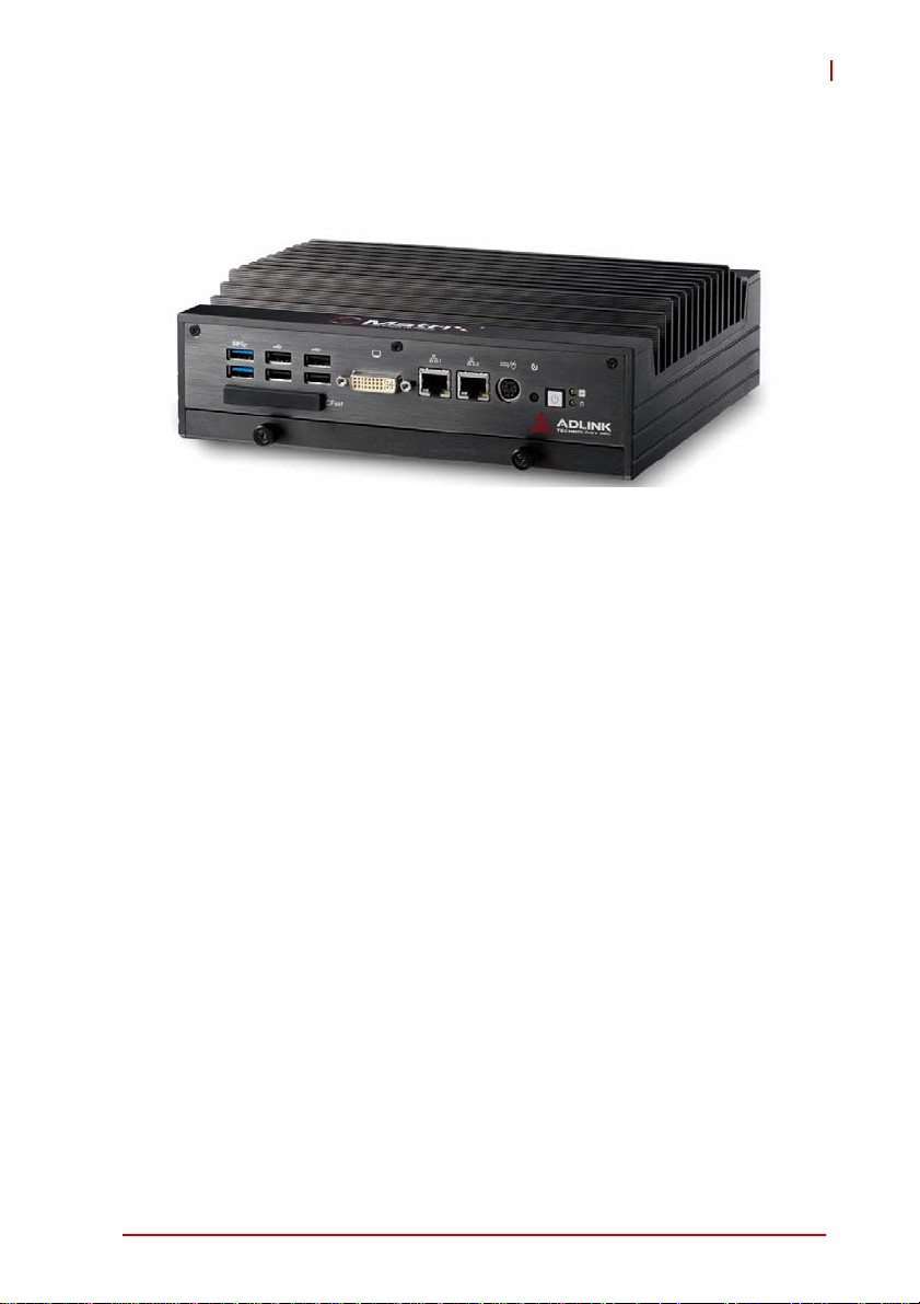
Figure 2-1: Front View
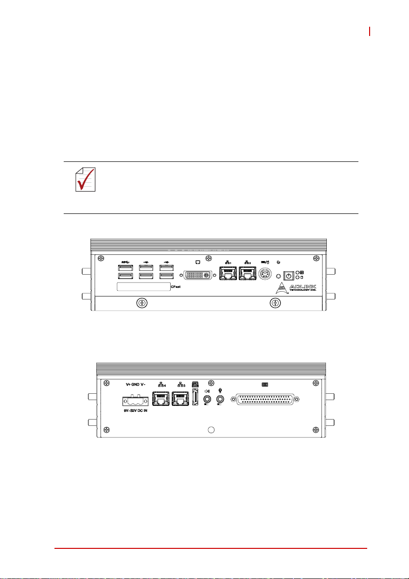
Figure 2-2: Rear View
System Description 7
Page 18

75
205.2
230
Figure 2-3: Top View
63
Figure 2-4: Side View
8System Description
Page 19
MXE-5300
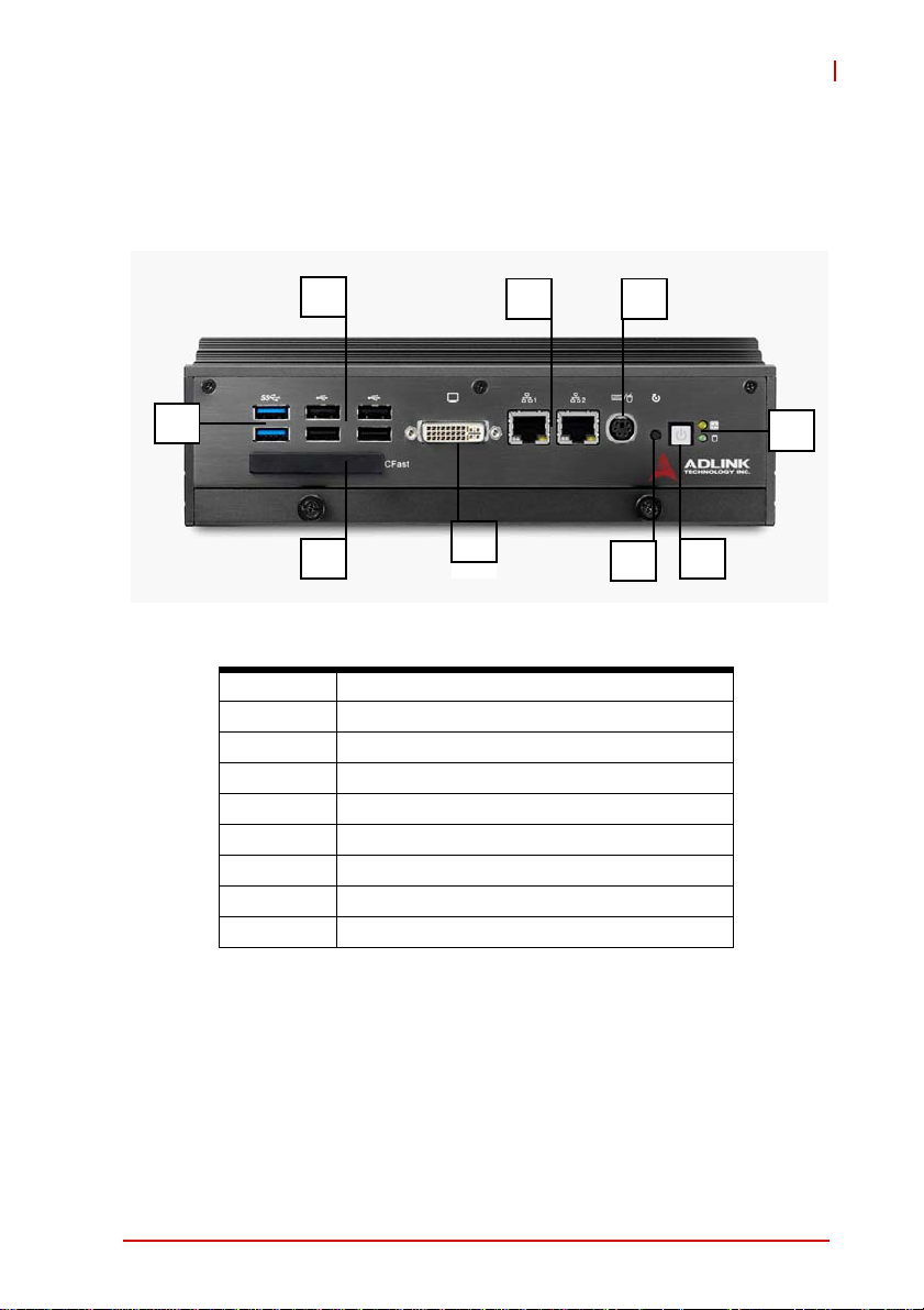
2.2 Front Panel I/O Connectors
This section describes the functions of the MXE-5300 I/O connectors
G
G
D E
D E
H
F
I
I
A LED Indicators
B Power Button
C Reset Button
D PS/2 keyboard & mouse
E Dual Gigabit Ethernet ports
F DVI-I connector
G USB 2.0 connector x4 (Type A)
H USB 3.0 connector x2 (Type A)
I CFast connector(Push-Push,Type II)
T able 2-1: MXE-5300 Front Panel Connectors
F
C
C
B
B
A
System Description 9
Page 20
2.2.1 LED Indicators
In addition to the LED of the power switch, two LEDs on the front
panel indicate the following.
LED indicator Color Description
X If lit continuously, indicates no
physical storage is connected
Diagnostic Yellow
X If blinking, indicates no mem-
ory is installed on either SODIMM socket
HDD Green
Table 2-2: LED Indicators
When blinking, indicates the SATA hard
drive is active
2.2.2 Power Switch
The power switch is non-latched, with a blue LED indicator. System is turned on when the button is depressed, and the power
LED lights. If the system hangs, depressing the switch for 5 seconds turns the system off completely.
2.2.3 Reset Button
The reset button executes a hard reset.
2.2.4 PS/2 Connector
The MXE-5300 provides connectors for PS/2 keyboard and
mouse, either singly or with a Y-cable to connect both at the same
time.
10 System Description
Page 21

MXE-5300
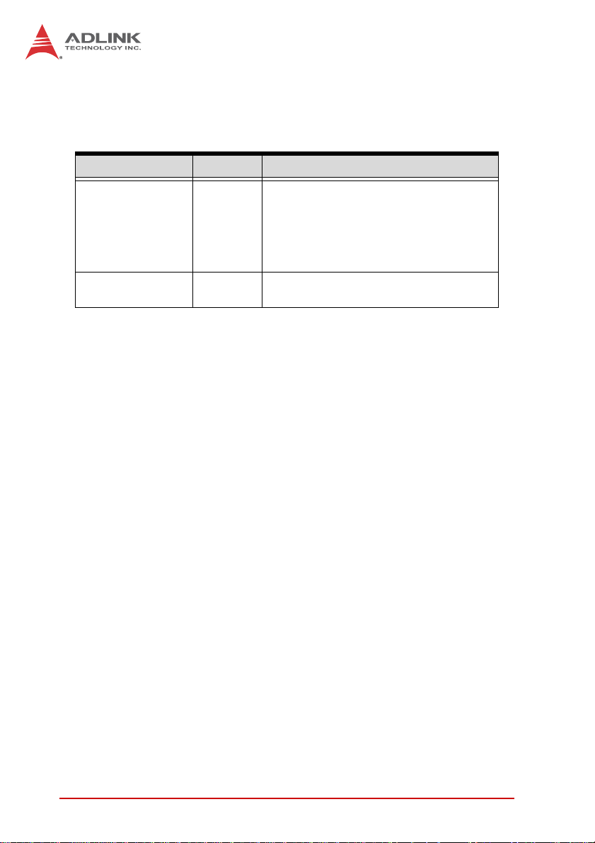
2.2.5 Dual Gigabit Ethernet Ports
The MXE-5300 provides two Gigabit Ethernet ports on the front
panel, an Intel® 82574IT Gigabit Ethernet Controller and Intel®
82579LM Gigabit Ethernet PHY, with features as follows.
Intel® 82574IT Gigabit Ethernet
Controller
Advanced error reporting 802.3x flow control-compliant
Message signaled interrupts IEEE 802.1p and 802.1q support
TCP segmentation offload/largesend support
802.3x flow control-compliant 10/100/1000 IEEE 802.3-compliant
IEEE 802.1p and 802.1q support
10/100/1000 IEEE 802.3-compliant Wake-On-LAN feature
Automatic MDI/MDIX crossover at all
speeds
ACPI 2.0 specification
Wake-On-LAN
Fully integrated ASF 2.0 functionality
with on-chip μc
SMBus 2.0 master interface for ASF
functionality
Preboot eXecution environment
(PXE) flash interface support
9 KB jumbo frame support IEEE 802.1p and 802.1q support
LAN Teaming Function support
Intel® 82579LM Gigabit Ethernet
PHY
Energy efficient
Ethernet(EEE)802.3az support
Automatic MDI/MDIX crossover at all
speeds
Support Intel® AMT 7.0
Reduced power consumption during
normal operation and power down
modes
Preboot eXecution Environment
(PXE) flash interface support
9 KB jumbo frame support
Supports LAN Teaming function
802.3x flow control-compliant
Energy Efficient
Ethernet(EEE)802.3az support
Table 2-3: Gigabit Ethernet Port Features
Both Gigabit Ethernet ports provide function indication through
LED display, as follows, with a yellow Activity indicator LED on the
right side of the port, and a green/orange Speed indicator LED on
the left. LED function is the same for both ports
System Description 11
Page 22
.
Figure 2-5: Gigabit Ethernet Ports
LED Color Status Description
OFF Ethernet port is disconnected.
Yell ow
LED Color Status Description
Green/
Orange
ON Ethernet port is connected with no activity.
Flashing Ethernet port is connected and active.
Table 2-4: Active/Link LED
OFF 10 Mbps
Green 100 Mbps
Orange 1000 Mbps
T able 2-5: Speed LED
12 System Description
Page 23
MXE-5300
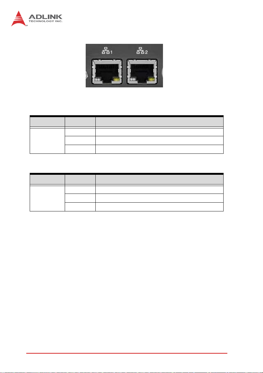
2.2.6 DVI-I Connector
The MXE-5300 provides one DVI-I connector for external monitor,
which can separate to VGA and DVI-D (single link) interfaces.
Pin Signal Name Pin Signal Name
1 DVI Data 2- 16 Hot plug detect
2 DVI Data 2+ 17 DVI Data 0-
3 GND 18 DVI Data 0+
4 CRT DDC clock 19 GND
5 CRT DDC data 20 N/C
6 DVI DDC clock 21 N/C
7 DVI DDC data 22 GND
8 Analog vertical sync 23 DVI clock +
9 DVI Data 1- 24 DVI clock -
10 DVI Data 1+
11 GND C1 Analog Red
12 N/C C2 Analog Green
13 N/C C3 Analog Blue
14 +5V C4 Analog horizontal sync
15 GND C5 Analog GND
Table 2-6: DVI-I Connector Pin Assignment
2.2.7 USB 2.0 Connectors
The MXE-5300 provides four Type A USB 2.0 ports on the front
panel. All are compatible with Hi-Speed, full-speed, and low-speed
USB devices.
The MXE-5300 supports multiple boot devices, including USB
flash, USB external HD, USB floppy, and USB CD-ROM drives.
System Description 13
Page 24

Boot priority and device can be configured in BIOS. Please refer to
Section 6.2.8 USB Configuration for details.
2.2.8 USB 3.0 Connectors
The MXE-5300 provides two Type A USB 3.0 ports on the front
panel. Based on the TI TUSB7320RKM USB host controller, connection to the host system is achieved through a PCIe x1 Gen2
interface, supporting SuperSpeed, Hi-Speed, full-speed, and lowspeed transmission for the downstream USB 3.0 ports.
The MXE-5300 supports multiple boot devices, including USB
flash, USB external HD, and USB CD-ROM drives. Boot priority
and device can be configured in BIOS.
While the USB 3.0 ports allow boot from CD-ROM, OS
installation via CD-ROM is not supported.
NOTE:
NOTE:
2.2.9 CFast Slot
The MXE-5300 is equipped with a type II push-push CFast host
connector on the front panel, connecting to the host controller by
SATA interface. Data transfer rates up to 3.0Gb/s(300MB/s)/
1.5Gb/s(150MB/s) are supported. The host SATA controller provides a legacy operating mode using I/O space, and an AHCI
operating mode using memory space. The CFast card can function as a storage device for system installation.
14 System Description
Page 25
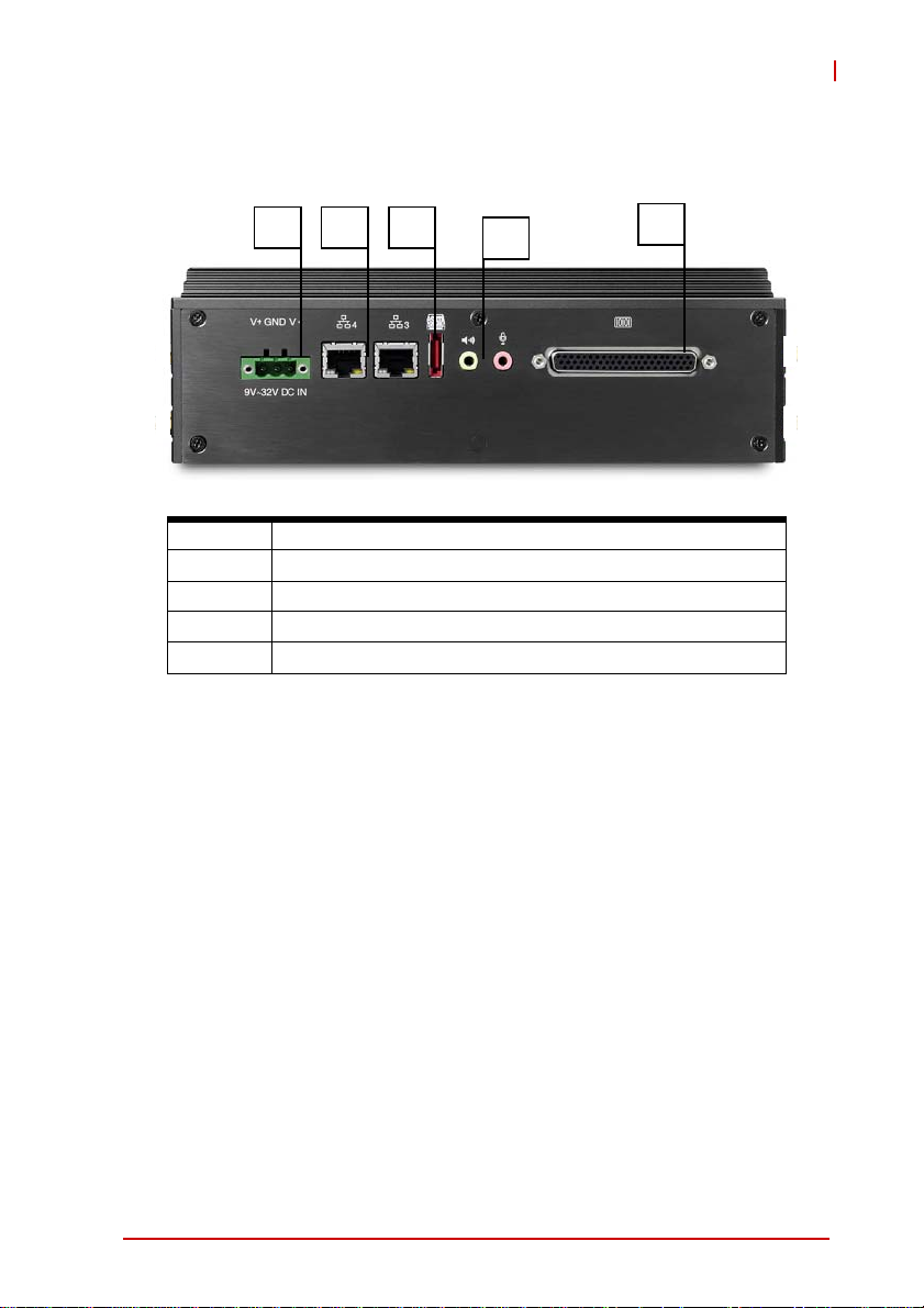
2.3 Rear Panel I/O Connectors
MXE-5300
K L M
K DC Power Supply Connector
L Dual Gigabit Ethernet ports
M eSATA Connector
N Audio Jacks
O DB-62P COM Ports and Digital I/O Connector
N
O
2.3.1 DC Power Supply Connector
The DC power supply connector of the MXE-5300, on the back
panel, consists of V-, chassis ground, and V+ pins, from right to
left. V+ and V- pins accept DC power input and the chassis ground
pin grounds the chassis for better EMC compatibility. The DC
power input of the MXE-5300 allows a voltage input range from 9
VDC to 32 VDC.
System Description 15
Page 26
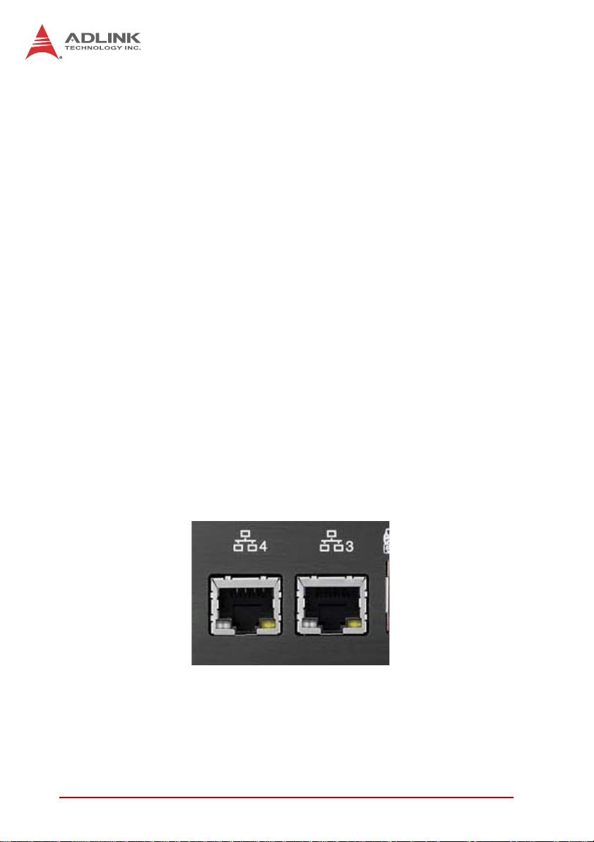
2.3.2 Dual Gigabit Ethernet Ports
The back panel provides two Gigabit Ethernet ports, both on
RealTek RTL8111C-VC-GR Gigabit Ethernet Controllers.
The RTL8111C-VC-GR supports:
X Integrated 10/100/1000 transceiver
X Auto-Negotiation with Next Page capability
X Supports pair swap/polarity/skew correction
X Crossover detection & Auto-Correction
X Wake-on-LAN and remote wake-up support
X Microsoft® NDIS5, NDIS6 checksum offload and segmenta-
tion task-offload support
X 802.3x flow control-compliant
X Fully compliant with IEEE802.3, IEEE 802.3u, IEEE802.3ab
X IEEE 802.1p and 802.1q support
X Supports power down/link down power saving
X Supports PCI MSI (message signal interrupt) and MSI-X
X Supports receive-side scaling (RSS)
X Preboot eXecution environment (PXE) flash interface sup-
port
LEDs on each rear panel LAN port provide the following operational information:
16 System Description
Page 27

MXE-5300
LED Color Status Description
Yellow OFF Ethernet port is disconnected.
ON Ethernet port is connected and no data
transmission.
Flashing Ethernet port is connected and transmitting/
receiving data.
Table 2-7: Active/Link LED
LED Color Status Description
Green/
Orange
OFF 10 Mbps
Green 100 Mbps
Orange 1000 Mbps
Table 2-8: Speed LED
2.3.3 eSATA Connector
One eSATA port connector is located on the back panel, supporting external SATA storage expansion at data transfer rates up to
3.0Gb/s(300MB/s) / 1.5Gb/s(150MB/s).
The host SATA controller provides two modes of operation: a legacy mode using I/O space, and an AHCI mode using memory
space. This connector supports only SATA singaling, and SATA
HDD or SSD requires connection to an external power supply for
operation.
2.3.4 Audio Jacks
The MXE-5300 implements Intel High Definition audio on a
Realtek ALC269 chip. The HD audio supports up to 24-bit, 192
KHz sample rate high quality headphone/speaker output and
microphone input. Access is provided by the pink jack for microphone input and the green jack for output.
System Description 17
Page 28

2.3.5 DB-62P COM Port and Digital I/O Connector
The MXE-5300 features 4 COM ports and 4-CH isolated digital
input and 4channel isolated digital output through a DB-62P connector on the back panel. Also provided is a cable connect to DB62P connector to extend four D-SUB 9-pin connectors and one
25-pin digital I/O connector. The COM1 and COM2 ports selectively support RS-232/ RS-422/ RS-485 mode by BIOS setting,
and RS-422/RS-485 mode also provides an optional choice of isolated 1.4 kV capability.
The residual COM3 and COM4 ports support RS-232 function
only.
Pin Signal Name Pin Signal Name Pin Signal Name
1 COM3_TXD 22 COM3_RXD 43 COM3_CTS#
2 COM3_DTR# 23 COM3_DSR# 44 COM3_RTS#
3 COM3_RI# 24 COM3_DCD# 45 GND
4 COM4_TXD 25 COM4_RXD 46 COM4_CTS#
5 COM4_DTR# 26 COM4_DSR# 47 COM4_RTS#
6 COM4_RI# 27 COM4_DCD# 48 GND
7 COM1_TXD 28 COM1_RXD 49 COM1_CTS#
8 COM1_DTR# 29 COM1_DSR# 50 COM1_RTS#
9 COM1_RI# 30 COM1_DCD# 51 GND
10 COM2_TXD 31 COM2_RXD 52 COM2_CTS#
11 COM2_DTR# 32 COM2_DSR# 53 COM2_RTS#
12 COM2_RI# 33 COM2_DCD# 54 GND
13 EOGND 34 GND 55 EOGND
18 System Description
Page 29

MXE-5300
Pin Signal Name Pin Signal Name Pin Signal Name
14 EOGND 35 IDO_3 56 EOGND
15 EOGND 36 IDO_2 57 EOGND
16 EOGND 37 IDO_1 58 EOGND
17 EOGND 38 IDO_0 59 EOGND
18 IDI_3L 39 IDI_3H 60 +V5DIO_CN_ISO
19 IDI_2L 40 IDI_2H 61 +VDD
20 IDI_1L 41 IDI_1H 62 +VDD
21 IDI_0L 42 IDI_0H
T able 2-9: DB-62P Connector Pin Assignment
Pin
RS-232 RS-422 RS-485
1 DCD# TXD422- 485DATA-
2 RXD TXD422+ 485DATA+
3 TXD RXD422+ N/C
4 DTR# RXD422- N/C
5 GND N/C N/C
6DSR# N/C N/C
7RTS# N/C N/C
8CTS# N/C N/C
9RI# N/C N/C
Table 2-10: D-SUB 9P COM Port Signal Nam es
System Description 19
Signal Name
Page 30

The onboard digital I/O card supports the following specs:
4-CH Isolated DI 4-CH Isolated DO
Logic high: 5 to 24 V
Logic low: 0 to 1.5 V
Input resistance: 2.4 k @ 0.5 W Supply voltage: 5 to 35 VDC
Interrupt source: DI Isolation voltage: 1.5KV DC
Isolation voltage: 1.5KV DC
channel 0 ~3
T a ble 2-11: Digital I/O Specifications
Pin Signal Name Pin Signal Name Pin Signal Name
1 EOGND 10 IDO_1 19 IDI_3L
2 +V5DIO_CN_ISO 11 EOGND 20 IDI_2H
3 +VDD 12 IDO_0 21 IDI_2L
4 +VDD 13 EOGND 22 IDI_1H
5EOGND14EOGND23IDI_1L
6 IDO_3 15 EOGND 24 IDI_0H
7EOGND16EOGND25IDI_0L
8 IDO_2 17 EOGND
9 EOGND 18 IDI_3H
Output Type: Open Drain N-
Channel Power MOSFET driver
250 mA for all channels @60℃,
100% duty
Table 2-12: D-SUB 25P Pin Assignment on Digital I/O port
Legend:
X IDO_n: Isolated digital output channel #n.
X IDI_nH: High input of isolated differential DI channel #n.
X IDI_nL: Low input of isolated differential DI channel #n.
X EOGND: Ground return path of isolated output channels.
X VDD: Power input signal for fly-wheel diode of DO chan-
nels.
20 System Description
Page 31

2.4 Internal I/O Connectors
MXE-5300
Figure 2-6: Mainboard Top View
(showing Clear CMOS and ME RTC Register Jumpers)
2.4.1 Clear CMOS and ME RTC Register Jumpers
Under abnormal conditions in which the MXE-5300 controller fails
to boot, clearing the BIOS content stored in CMOS and restoring
the default settings may be effective. To clear CMOS, shorten
System Description 21
Page 32

Pin#1 and Pin#2 of JP1 and remove the jumper, after which the
CMOS will be restored to factory default settings.
Normal Clear
Table 2-13: Clear CMOS Jumper
As with JP1, shorting Pin#1 and #2 of JP2 will clear the ME
RTC register, however, since this jumper is used by RMA, user
CAUTION:
clearance of the ME RTC register may cause unexpected
errors in system behavior.
22 System Description
Page 33

MXE-5300
B
A
C
D
Figure 2-7: Mainboard Underside View
A Mini-PCIe Connectors (Default: Rev.1.2, Option: Rev.1.1)
B DC 5V and 3.3V Connectors for GPS Module
C USIM Port
D SATA Connectors
2.4.2 Mini-PCIe Connector
Mini-PCIe connectors provide function expansion by enabling
installation of a third party Mini-PCIe module such as a WiFi module, 3.5G module, or other.
System Description 23
Page 34

2.4.3 DC 5V and 3.3V Connectors for GPS Module
Two power connectors are provided for GPS module use, one 5V
and the other 3.3V, with maximum current rating of each 1A.
2.4.4 USIM Port
Use of a 3.5G mini-PCIe module normally requires a SIM card to
support communication with a telecom operator. The MXE-5300
provides a USIM port connected to mini-PCIe connector. The SIM
card and 3.5G mini-PCIe module can be installed to facilitate 3.5G
communication.
2.4.5 SATA Connector
Two SATA connectors support data transfer up to 6.0Gb/s(600MB/
s). The SATA host controller supports a legacy mode using I/O
space and AHCI mode using memory space. The SATA connector
is compatible with a 2.5 in hard disk drive (HDD) or solid state disk
(SSD). The HDD or SSD must be installed into the SATA connector with a HDD bracket.
24 System Description
Page 35

3 Getting Started
This chapter discusses installation of hard disk drive, memory, and
CFast card. In addition to connection and use of DIO and COM
ports, wall-mount installation is also described.
3.1 Installing a Hard Disk Drive
Before installing a hard disk drive, remove the bottom cover of the
chassis as follows.
1. Remove the thumbscrews on the front panel by hand or
a screwdriver.
MXE-5300
2. Withdraw the thumbscrews and remove the bottom
cover by pulling and lifting.
Getting Started 25
Page 36

3. Remove the mounting screw from the top of the HDD
bracket.
26 Getting Started
Page 37

MXE-5300
4. Pull and lift the HDD bracket.
5. Use the 4 included M3-F head screws to fix one 2.5”
HDD or SSD to the bracket.
Getting Started 27
Page 38

6. Install the 2.5’’ HDD or SSD to the SATA connector.
7. Reassemble the chassis.
28 Getting Started
Page 39

MXE-5300
3.2 Installing Memory
Before installing RAM, the bottom cover must be removed, as
described in steps 1 and 2 of Section 3.1.
1. Remove 3 M3-P head screws from the top of the RAM
bracket.
2. Remove 2 M3-F head screws from the front panel.
Getting Started 29
Page 40

3. Pull and lift the RAM bracket.
4. Insert DDRIII SODIMM RAM into the slot at an angle.
30 Getting Started
Page 41

MXE-5300
5. Depress RAM until the latch catches and RAM is
securely fixed.
Getting Started 31
Page 42

3.3 Installing CFast Cards
The MXE-5300 series provides an external CFast socket to
accommodate one CFast card, acting as a replacement of the
hard disk drive.
1. Remove and rotate the CFast cover to expose the slot
.
2. Gently insert the CFast card into the CFast socket.
32 Getting Started
Page 43

MXE-5300
3. Rotate the CFast cover to its orginal position and
replace.
Getting Started 33
Page 44

3.4 COM Ports and DIO Device
The MXE-5300 series controller integrates 4 COM ports and 4 digital input and 4 digital output ports into a connector, The included
breakout cable can connect COM ports and the DIO device.
1. Connect the cable to the connector on the rear panel
.
34 Getting Started
Page 45

MXE-5300
2. The 4 COM ports cables are numbered 1 to 4, with 1 and
2 connecting to RS-232 interface devices and 3 and 4 to
RS-422 or RS-485 interface devices.
3. The DIO cable connects to a terminal board for digital
input and output.
Getting Started 35
Page 46

3.5 Connecting to DC power
Before introducing DC power to the MXE-5300 controller,
ensure the voltage and polarity provided are compatible with
the DC input. Improper input voltage and/or polarity can be
responsible for system damage
The DC power input connector of the MXE-5300 utilizes V+, V-,
and chassis ground pins, and accepts input voltage as shown previously.
1. Connect the DC power as shown
2. Fix the DC connector using the 2 screws.
36 Getting Started
Page 47

MXE-5300
3.6 Wall-mounting the MXE-5300
The MXE-5300 controller is shipped with wall-mount brackets and
accessory screws, with mounting procedures as follows.
1. Prepare the two wall-mount brackets and 4 M4-P head
screws included in the package.
Getting Started 37
Page 48

2. Remove the 4 plastic pads from the corners of the chassis underside.
3. With the 4 included M4-P head screws, fix the 2 wallmount brackets, also included, to the chassis, according
to the spacing dimensions of the screw holes and brackets, as shown.
38 Getting Started
Page 49

MXE-5300
Getting Started 39
Page 50

4. Once final assembly as shown is complete, mount the
MXE-5300 series controller on the wall via the screw
holes.
3.7 Thermal Considerations
Heat-generating components of the MXE-5300 (such as CPU and
PCH) are all situated on the left side of the system. These components directly contact the heat sink via thermal pads and dissipate
heat generated by the components. To maximize efficiency of heat
dissipation, a minimum of 2 inches (5 cm) clearance should be
maintained on the top of the chassis.
40 Getting Started
Page 51

4 Driver Installation
This section describes the drivers needed for Windows operating
systems and the procedures to install them. For other OS support,
please contact ADLINK for further information.
Properly install Windows before installing any drivers. Most standard I/O device drivers have been included in Windows. The following drivers must be installed:
X Chipset
X Graphics
X Ethernet
X WDT (watchdog timer)
4.1 Installing the Chipset Driver
The chipset driver directs the operating system in configuration of
the Intel
of:
®
QM67 chipset components to guarantee performance
X Core PCI and ISAPNP Services
X PCIe Support
X SATA Storage Support
X USB Support
X Identification of Intel
®
Chipset Components in the Device
Manager
MXE-5300
One of the following operating systems must be fully installed and
running on the system before installing this software:
X Microsoft Windows XP
X Microsoft windows 7
To install the chipset driver for the MXE-5300 :
1. Close any running applications.
2. Insert the ADLINK All-in-One DVD; the chipset driver is
located in the directory: x:\Driver Installa-
Driver Installation 41
Page 52

tion\Matrix\MXE-5300\Chipset\ (where x: denotes the
DVD-ROM drive)
3. Execute Setup.exe and follow the onscreen instructions
to complete the setup.
4. After installation is complete, reboot the system.
4.2 Installing the Graphics Driver
The MXE-5300 is equipped with the Intel® HD Graphic 3000
graphics media accelerator integrated in Intel Mobile Intel® ATOM.
The Intel
Windows 7 and Windows XP.
To install the graphics driver.
®
Graphics Media Accelerator Driver package supports
1. Close any running applications.
2. Insert the ADLINK All-in-One DVD; the graphics driver is
located in the directory: x:\Driver Installation\Matrix\MXE-5300\Graphics\ (where x: denotes the
DVD-ROM drive).
3. Execute Setup.exe and follow the onscreen instructions
to complete the setup.
4. After installation is complete, reboot the system.
4.3 Installing the Ethernet Driver
To install the driver for Realtek 8111C Gigabit Ethernet controller,
for Windows 7 and XP users:
1. Close any running applications.
2. Insert the ADLINK All-in-One DVD; the Ethernet driver is
located in the directory: x:\Driver Installation\Matrix\MXE-5300\LAN-Realtek\ (where x: denotes
the DVD-ROM drive).
3. Execute Setup.exe and follow the onscreen instructions
to complete the setup.
4. After installation is complete, reboot the system.
42 Driver Installation
Page 53

MXE-5300
To install the driver for Intel 82547 Gigabit Ethernet controller, for
Windows 7 and XP users:
1. Close any running applications.
2. Insert the ADLINK All-in-One DVD; the Ethernet driver is
located in the directory: x:\Driver Installation\Matrix\MXE-5300\LAN-Intel\ (where x: denotes the
DVD-ROM drive).
3. Execute Setup.exe and follow the onscreen instructions
to complete the setup.
4. After installation is complete, reboot the system.
4.4 Installing the Audio Driver
The MXE-5300 supports Intel High Definition audio using Realtek
ALC269 audio codec. To install the audio driver for MXE-5300, for
Windows 7, XP, and Vista users:
1. Close any running applications.
2. Insert the ADLINK All-in-One DVD; the audio driver is
located in the directory:x:\Driver Installation\Matrix\MXE5300\Audio\ (where x: denotes the DVD-ROM drive).
3. Execute Setup.exe and follow the onscreen instructions
to complete the setup.
4. After installation is complete, reboot the system.
4.5 Installing the WDT Driver
A WDT (watchdog timer) is a hardware mechanism resetting the
system when the operating system or application is halted. A typical usage of WDT is to start and periodically reset timers, and
when a timer is expired, the system resets.
To install the WDT driver for the MXE-5300:
1. Close any running applications.
2. Insert the ADLINK All-in-One DVD; the WDT driver is
located in the directory: x:\Driver Installa-
Driver Installation 43
Page 54

tion\Matrix\MXE-5300\WDT\ (where x: denotes the DVDROM drive).
3. Execute Setup.exe and follow the onscreen instructions
to complete the setup.
4. After installation is complete, reboot the system.
44 Driver Installation
Page 55

5 BIOS Settings
The Basic Input/Output System (BIOS) is a program that provides
a basic level of communication between the processor and peripherals. In addition, the BIOS also contains codes for various
advanced features applied to the MXE-5300. The BIOS setup program includes menus for configuring settings and enabling features of MXE-5300. Most users do not need to use the BIOS setup
program, as the MXE-5300 controller ships with default settings
that work well for most configurations.
BIOS options in the manual are for reference only. Different
configurations may lead to actual BIOS displayed differing from
NOTE:
NOTE:
CAUTION:
that shown here. Users are welcome to download the latest
BIOS version from our website.
Changing BIOS settings may lead to incorrect controller behavior and possible inability to boot. In such a case, see
Section 2.4.1: Clear CMOS and ME RTC Register Jumpers for
instruction on clearing the CMOS and restoring default settings.
MXE-5300
BIOS Settings 45
Page 56

5.1 Main
5.1.1 BIOS Information
Shows current system BIOS code version and BIOS version.
5.1.2 System Time/System Date
Use this option to change the system time and date. Highlight System Time or System Date using the up or down <Arrow> keys.
Enter new values using the keyboard then <Enter>. Enter < Tab >
to move between fields. The date must be entered in MM/DD/YY
format. The time is entered in HH:MM:SS format.
The time is in 24-hour format. For example, 5:30 A.M. appears
as 05:30:00, and 5:30 P.M. as 17:30:00.
NOTE:
NOTE:
46 BIOS Settings
Page 57

5.2 Advanced
MXE-5300
Setting incorrect or conflicting values in Advanced BIOS Setup
may cause system malfunctions.
CAUTION:
BIOS Settings 47
Page 58

5.2.1 ACPI Settings
Enable ACPI Auto Configuration
Enables or disables BIOS ACPI Auto Configuration.
Enable Hibernation
Enables or disables system's ability to hibernate. This option
may be not effective with some OS.
ACPI Sleep State
Selects the highest ACPI sleep state the system will enter
when the SUSPEND button is pressed.
Lock Legacy Resource
Enables or disables lock of legacy resource to prevent changes
in IO resource for legacy devices like serial ports.
48 BIOS Settings
Page 59

5.2.2 CPU Configuration
MXE-5300
Limit CPUID Maximum
Disabled for Windows XP.
Execute Disable Bit
Enables XD to prevent certain classes of malicious buffer overflow attacks when combined with a supporting OS.
Hardware Prefetcher
Enables or disables the Mid Level Cache (L2) streamer
prefetcher.
Adjacent Cache Line Prefetch
Enables or disables the prefetching of adjacent cache lines.
BIOS Settings 49
Page 60

Intel Virtualization Technology
When enabled, a VMM can utilize the additional hardware
capabilities provided by Vanderpool Technology.
Local x2APIC
Enables Local x2APIC, some OS do not support this.
EIST
Enables/disables Intel SpeedStep Technology.
Turbo Mode
Enables/disables Intel TurboBoost Technology.
C1E Function
When enabled, lets CPU enter enhanced C1 sleep state to
save more power than C1.
CPU C3 Support
Enables/disables CPU C3(ACPI C2) report to OS.
CPU C6 Support
Enables/disables CPU C6(ACPI C3) report to OS.
CPU C7 Support
Enables/disables CPU C7(ACPI C3) report to OS.
50 BIOS Settings
Page 61

5.2.3 Onboard Device Configuration
MXE-5300
Intel 82579LM LAN
Enables/disables onboard Intel 82579LM (built-in PCH) LAN
controller.
Launch Intel 82579LM LAN PXE OpROM
Enables or disables execution of LAN boot-rom to add
boot option for legacy network devices.
Intel 82574 LAN
Enables/disables onboard Intel 82574 LAN controller.
Launch Intel 82574 LAN PXE OpROM
Enables or disables execution of LAN boot-rom to add
boot option for legacy network devices.
RealTek 8111C LAN #1 (Appear on MXE5300 only)
Enables/disables onboard RealTek 8111C LAN controller.
BIOS Settings 51
Page 62

Launch RealTek 8111C PXE OpROM
Enables or disables execution of LAN boot-rom to add
boot option for legacy network devices.
RealTek 8111C LAN #2 (Appear on MXE5300 only)
Enables/disables onboard RealTek 8111C LAN controller.
Launch RealTek 8111C PXE OpROM
Enables or disables execution of LAN boot-rom to add
boot option for legacy network devices.
5.2.4 Advanced Power Management
52 BIOS Settings
Page 63

MXE-5300
Restore On AC Power Loss
Determines the state the computer enters when power is
restored after a power loss. Options for this value are Last
State, Power On and Power Off.
Option Description
Power Off
Power On
Last State
When set, powers the system down when
power is restored.
When set, powers the system on when power
is restored.
When set, powers the system down or on
depending on the last system power state
when power is restored.
Table 5-1: Restore On Power Loss
Wake up system by 82579L LAN in S5
Enables or disables integrated LAN to wake the system in S5
state.
RTC Wakeup in S5
Enables or disables system wake on alarm event.
System watchdog
Enables or disables system internal watchdog to prevent boot
failure during system POST stage.
BIOS Settings 53
Page 64

5.2.5 SATA Configuration
SATA Controller(s)
Enables/disables internal serial ATA controller
SATA Mode Selection
This option selects the SATA channel configuration from
among (1) IDE Mode or (2) AHCI Mode
Serial ATA Port 0 / C-Fast Port / E-SATA Port
Port X
Enables or disables SATA Port X
Hot Plug
Sets this port as hot pluggable.
54 BIOS Settings
Page 65

5.2.6 Intel Anti-Theft Technology Configuration
MXE-5300
5.2.7 Intel Anti-Theft Technology
Enables or disables Intel AT function. Intel® Anti-Theft Technology
helps stop theft by making computers non-functional with immediate shutdown.
Intel Anti-Theft Technology Recovery/Enter Intel AT suspend
mode
Miscellaneous settings for Intel AT function.
BIOS Settings 55
Page 66

5.2.8 AMT Configuration
Intel AMT
Enables/disables Intel AMT function.
Intel AMT Setup Prompt
Enables/disables launching of MEBx during system post for
configuring AMT features.
BIOS Hotkey Pressed/MEBx Selection Screen
Miscellaneous settings for iAMT function.
56 BIOS Settings
Page 67

5.2.9 USB Configuration
MXE-5300
Legacy USB Support
AUTO option disables legacy support if no USB devices are
connected, DISABLE option keeps USB devices available only
for EFI applications.
USB3.0 Support
Enables or disables USB3.0 (XHCI) controller support, allowing
USB 3.0 devices to be used in DOS environment.
XHCI Hand-Off
Enables BIOS support of XHCI Hand-Off feature. Default
option is Enabled.
EHCI Hand-Off
Enables BIOS support of EHCI Hand-Off feature. Default
option is Enabled.
BIOS Settings 57
Page 68

5.2.10 Super IO Configuration
Serial Port 1 to 4 Configuration
Can enable/disable the port, select port type (RS-232/422/485)
for Serial Port 1 and 2 only, or change the port settings
(address).
58 BIOS Settings
Page 69

5.2.11 H/W Monitor
MXE-5300
PC Health Status
The hardware health on Super I/O supports Board Temperature 1/2, CPU Temperature, CPU Voltage, I-GFX Voltage,
VCCSA Voltage, +1.05V, +3.3V, +1.5V, +5V, +12.0V, and
VBAT.
BIOS Settings 59
Page 70

5.2.12 Serial Port Console Redirection
COM 1 to 4, SOL (Serial Over LAN) COM
Console Redirection
Enables console redirection of COM 1 to 4, SOL COM.
Console Redirection Settings
Miscellaneous parameters for COM Port 1 to 4, SOL
COM.
Serial Port for Out-of-Band Management/EMS
Console Redirection
Enables console redirection for remote management of
a Windows Server OS through the port selected by Outof-Band Mgmt Port.
60 BIOS Settings
Page 71

Out-of-Band Mgmt Port
Selects the COM Port for remote management of a Windows OS.
Terminal Type
Selects the transmission protocol for remote terminal
console.
5.3 Chipset
MXE-5300
BIOS Settings 61
Page 72

5.3.1 System Agent (SA) Configuration
VT-d
Enables VT-d function for efficient virtualization of I/O devices.
Graphics Configuration
Selects internal graphic device shared memory size and power
policy.
62 BIOS Settings
Page 73

Graphics Turbo IMON Current
MXE-5300
Sets the maximum IMON current value for graphics turbo
mode.
GTT Size
Selects GTT size for internal graphics.
DVMT Pre-Allocated
Selects DVMT 5.0 pre-allocated graphics memory size used by
the internal graphics device.
DVMT Total Gfx Memory
Selects DVMT 5.0 total graphics memory size used by the
internal graphics device.
BIOS Settings 63
Page 74

5.4 Boot
5.4.1 Boot Configuration
Setup Prompt Timeout
Number of seconds to wait for setup activation key (DEL).
Bootup Num-Lock State
Allows Number Lock setting to be modified during boot.
Quiet Boot
When Disabled, directs BIOS to display POST messages;
when Enabled, directs BIOS to display the OEM logo.
64 BIOS Settings
Page 75

MXE-5300
5.4.2 Boot Option Priorities
Specifies the priority of boot devices, with all installed boot devices
detected during POST and displayed, selecting Boot Option #
specifies the desired boot device.
5.5 Security
If only the Administrator’s password is set, only access to Setup is
limited and is only requested when entering Setup. If only the
user’s password is set, power on requires a password which must
be entered to boot or enter setup. In Setup the user has Administrator rights.
Administrator Password
Sets Administrator password
BIOS Settings 65
Page 76

User Password
Sets boot/setup User password
5.6 Exit
Save Changes and Exit
When BIOS settings are complete, selecting this option saves
all changes and reboots the system, and new settings take
effect.
Discard Changes and Exit
Discards all changes and exits BIOS setup.
Discard Changes and Reset
Resets system setup without saving any changes.
66 BIOS Settings
Page 77

MXE-5300
Restore Defaults
Returns all BIOS options to Default settings, designed for maximum system stability, but not performance. Applicable in the
event of system configuration problems.
Launch EFI Shell from filesystem device
Attempts to launch EFI Shell application (Shellx64.efi) from one
of the available filesystem devices.
BIOS Settings 67
Page 78

This page intentionally left blank.
68 BIOS Settings
Page 79

Appendix A WDT Function Reference
A.1 Watchdog Timer (WDT) Function Reference
This appendix describes the usage of the watchdog timer (WDT)
function library for the MXE-5300 controller. Watchdog timer is a
hardware mechanism to reset the system in case the operating
system or an application halts. After starting watchdog timer, you
need to periodically reset the watchdog timer in the application
before the timer expires. Once watchdog timer expires, a hardware-generated signal is sent to reset the system.
To use the WDT function library for MXE-5300, you need to
include the header file WDT.h and linkage library WDT.lib in your
C++ project.
InitWDT
Description
Initializes the watchdog timer function of MXE-5300 controller.
InitWDT must be called before the invocation of any other WDT
function.
Supported controllers
MXE-5300
MXE-5300
Syntax
C/C++
BOOL InitWDT()
Parameters
None
Return code
TRUE if watchdog timer is successfully initialized.
FALSE if watchdog timer is failed to initialize.
WDT Function Reference 69
Page 80

MXE-5300
SetWDT
Description
Set the timeout value of watchdog timer. There are two parameters for this function to indicate the timeout ticks and unit.
Users should call ResetWDT or StopWDT before the expiration
of watchdog timer, or the system will be reset.
Supported controllers
MXE-5300
Syntax
C/C++
BOOL SetWDT(BYTE tick, BYTE unit)
Parameters
tick
Specify the number of tick for watchdog timer. A valid value
is 1 - 255.
unit
Specify the timeout ticks of the watchdog timer.
Value Description
The unit of tick is second. For example, when you specify tick
0
as 100 and unit as 0, the timeout value is 100 seconds.
The unit of tick is minute. For example, when you specify tick
1
as 100 and unit as 1, the timeout value is 100 minutes.
Return codes
TRUE if timeout value of watchdog timer is successfully set.
FALSE if timeout value of watchdog timer is failed to set.
70 WDT Function Reference
Page 81

StartWDT
Description
Start the watchdog timer function. Once the StartWDT is
invoked, the countdown of watchdog timer starts. Users should
call ResetWDT or StopWDT before the expiration of watchdog
timer, or the system will be reset.
Supported controllers
MXE-5300
Syntax
C/C++
BOOL StartWDT()
Parameters
None
Return codes
TRUE if watchdog timer is successfully started.
FALSE if watchdog timer is failed to start.
MXE-5300
ResetWDT
Description
Reset the watchdog timer. The invocation of ResetWDT allows
users to restore the watchdog timer to the initial timeout value
specified in SetWDT function. Users should call ResetWDT or
StopWDT before the expiration of watchdog timer, or the system will be reset.
Supported controllers
MXE-5300
Syntax
C/C++
BOOL ResetWDT()
Parameters
None
WDT Function Reference 71
Page 82

MXE-5300
Return codes
TRUE if watchdog timer is successfully reset.
FALSE if watchdog timer is failed to reset.
StopWDT
Description
Stop the watchdog timer.
Supported controllers
MXE-5300
Syntax
C/C++
BOOL StopWDT()
Parameters
None
Return codes
TRUE if watchdog timer is successfully stopped.
FALSE if watchdog timer is failed to stop.
72 WDT Function Reference
Page 83

PXIe-3975
Important Safety Instructions
For user safety, please read and follow all instructions,
WARNINGS, CAUTIONS, and NOTES marked in this manual and
on the associated equipment before handling/operating the
equipment.
X Read these safety instructions carefully.
X Keep this user’s manual for future reference.
X Read the specifications section of this manual for detailed
information on the operating environment of this equipment.
X When installing/mounting or uninstalling/removing
equipment:
Z Turn off power and unplug any power cords/cables.
X To avoid electrical shock and/or damage to equipment:
Z Keep equipment away from water or liquid sources;
Z Keep equipment away from high heat or high humidity;
Z Keep equipment properly ventilated (do not block or
cover ventilation openings);
Z Make sure to use recommended voltage and power
source settings;
Z Always install and operate equipment near an easily
accessible electrical socket-outlet;
Z Secure the power cord (do not place any object on/over
the power cord);
Z Only install/attach and operate equipment on stable
surfaces and/or recommended mountings; and,
Z If the equipment will not be used for long periods of time,
turn off and unplug the equipment from its power source.
Important Safety Instructions 73
Page 84

X Never attempt to fix the equipment. Equipment should only
be serviced by qualified personnel.
X A Lithium-type battery may be provided for uninterrupted,
backup or emergency power.
Risk of explosion if battery is replaced with an incorrect type;
please dispose of used batteries appropriately.
X Equipment must be serviced by authorized technicians
when:
Z The power cord or plug is damaged;
Z Liquid has penetrated the equipment;
Z It has been exposed to high humidity/moisture;
Z It is not functioning or does not function according to the
user’s manual;
Z It has been dropped and/or damaged; and/or,
Z It has an obvious sign of breakage.
74 Important Safety Instructions
Page 85

Getting Service
Contact us should you require any service or assistance.
ADLINK Technology, Inc.
Address: 9F, No.166 Jian Yi Road, Zhonghe District
New Taipei City 235, Taiwan
ᄅקؑխࡉ৬ԫሁ 166 ᇆ 9 ᑔ
Tel: +886-2-8226-5877
Fax: +886-2-8226-5717
Email: service@adlinktech.com
Ampro ADLINK Technology, Inc.
Address: 5215 Hellyer Avenue, #110, San Jose, CA 95138, USA
Tel: +1-408-360-0200
Toll Free: +1-800-966-5200 (USA only)
Fax: +1-408-360-0222
Email: info@adlinktech.com
ADLINK Technology (China) Co., Ltd.
Address: Ϟ⍋Ꮦ⌺ϰᮄᓴ∳催⾥ᡔು㢇䏃 300 ো(201203)
300 Fang Chun Rd., Zhangjiang Hi-Tech Park,
Pudong New Area, Shanghai, 201203 China
Tel: +86-21-5132-8988
Fax: +86-21-5132-3588
Email: market@adlinktech.com
ADLINK Technology Beijing
Address: ࣫ҀᏖ⍋⎔Ϟഄϰ䏃 1 োⲜ߯ࡼ E ᑻ 801 ᅸ(100085)
Rm. 801, Power Creative E, No. 1, B/D
Shang Di East Rd., Beijing, 100085 China
Tel: +86-10-5885-8666
Fax: +86-10-5885-8625
Email: market@adlinktech.com
MXE-5300
ADLINK Technology Shenzhen
Address: ⏅ഇᏖቅ⾥ᡔು催ᮄϗ䘧᭄ᄫᡔᴃು
Tel: +86-755-2643-4858
Fax: +86-755-2664-6353
Email: market@adlinktech.com
ADLINK Technology (Europe) GmbH
Address: Nord Carree 3, 40477 Duesseldorf, Germany
Tel: +49-211-495-5552
Fax: +49-211-495-5557
Email: emea@adlinktech.com
A1 2 ὐ C (518057)
2F, C Block, Bldg. A1, Cyber-Tech Zone, Gao Xin Ave. Sec. 7,
High-Tech Industrial Park S., Shenzhen, 518054 China
Getting Service 75
Page 86

MXE-5300
ADLINK Technology, Inc. (French Liaison Office)
Address: 15 rue Emile Baudot, 91300 Massy CEDEX, France
Tel: +33 (0) 1 60 12 35 66
Fax: +33 (0) 1 60 12 35 66
Email: france@adlinktech.com
ADLINK Technology Japan Corporation
Address: ͱ101-0045 ᵅҀ䛑ҷ⬄⼲⬄䤯ފ⬎ 3-7-4
Tel: +81-3-4455-3722
Fax: +81-3-5209-6013
Email: japan@adlinktech.com
ADLINK Technology, Inc. (Korean Liaison Office)
Address: 昢殾柢 昢爎割 昢爎壟 1675-12 微汾瘶捒娯 8猻
Tel: +82-2-2057-0565
Fax: +82-2-2057-0563
Email: korea@adlinktech.com
ADLINK Technology Singapore Pte. Ltd.
Address: 84 Genting Lane #07-02A, Cityneon Design Centre,
Tel: +65-6844-2261
Fax: +65-6844-2263
Email: singapore@adlinktech.com
⼲⬄ 374 ɛɳ 4F
KANDA374 Bldg. 4F, 3-7-4 Kanda Kajicho,
Chiyoda-ku, Tokyo 101-0045, Japan
8F Mointer B/D,1675-12, Seocho-Dong, Seocho-Gu,
Seoul 137-070, Korea
Singapore 349584
ADLINK Technology Singapore Pte. Ltd. (Indian Liaison Office)
Address: 1st Floor, #50-56 (Between 16th/17th Cross) Margosa Plaza,
Tel: +91-80-65605817, +91-80-42246107
Fax: +91-80-23464606
Email: india@adlinktech.com
ADLINK Technology, Inc. (Israeli Liaison Office)
Address: 6 Hasadna St., Kfar Saba 44424, Israel
Tel: +972-9-7446541
Fax: +972-9-7446542
Email: israel@adlinktech.com
Margosa Main Road, Malleswaram, Bangalore-560055, India
76 Getting Service
 Loading...