

Page 1

Matrix MXC-4000 Series
User’s Manual
Manual Revision: 2.01
Revision Date: June 23, 2011
Part Number: 50-1Z068-1010
Advance Technologies; Automate the World.
Page 2

Matrix MXC-4000 Series
User’s Manual
This page intentionally left blank.
ii
Page 3

Matrix MXC-4000 Series
User’s Manual
Table of Contents
Table of Contents................................................................... iii
List of Tables........................................................................... v
1 Introduction ........................................................................ 1
1.1 Overview.............................................................................. 1
1.2 Specifications....................................................................... 3
1.3 Unpacking Checklist ............................................................ 5
2 System Description............................................................ 7
2.1 Mechanical Drawings........................................................... 7
2.1.1 Front View........................................................................ 7
2.1.2 Rear View ........................................................................ 8
2.1.3 Side View (Left) ............................................................... 9
2.1.4 Side View (Right) ............................................................. 9
2.1.5 Bottom View................................................................... 10
2.1.6 Top View........................................................................ 10
2.2 Front Panel I/O Connectors ............................................... 11
2.2.1 Power Button ................................................................. 12
2.2.2 LED Indicators ............................................................... 12
2.2.3 Reset Button .................................................................. 12
2.2.4 Digital I/O Connector ..................................................... 13
2.3 Operating Principles .......................................................... 15
2.3.1 Isolated Digital Input ...................................................... 15
2.3.2 Isolated digital Output .................................................... 16
2.4 Gigabit Ethernet (WG82574L) ........................................... 18
2.4.1 USB 2.0 connectors....................................................... 19
2.4.2 LVDS Connector............................................................ 20
2.4.3 COM Ports..................................................................... 20
2.4.4 VGA Connector.............................................................. 22
2.4.5 E-SATA Connectors ...................................................... 23
Table of Contents iii
Page 4

Matrix MXC-4000 Series
User’s Manual
2.4.6 Audio Jacks ................................................................... 24
2.4.7 Keyboard & Mouse PS2 Connectors ............................. 24
2.4.8 Power Input Connector .................................................. 25
2.5 Internal I/O Connectors...................................................... 26
2.5.1 CompactFlash Socket.................................................... 27
2.5.2 Fan Connector ............................................................... 27
2.5.3 SATA Connector............................................................ 27
2.5.4 Clear CMOS Button ....................................................... 28
3 Getting Started .................................................................. 29
3.1 Installing a hard disk drive ................................................. 29
3.2 Installing PCI/PCIe card..................................................... 35
3.3 Installing a CF Card ........................................................... 38
3.4 Plug-in DC power............................................................... 40
3.5 Mounting MXC4000 Series Controller ............................... 41
4 BIOS Settings and Driver Installation ............................. 45
4.1 BIOS Setting ...................................................................... 45
4.1.1 Main ............................................................................... 45
4.1.2 Advanced....................................................................... 46
4.1.3 Chipset........................................................................... 51
4.1.4 Security.......................................................................... 54
4.1.5 Boot ............................................................................... 55
4.1.6 Exit................................................................................. 57
4.2 Driver Installation ............................................................... 58
4.2.1 Install the Chipset Driver................................................ 59
4.2.2 Install the Graphics Driver ............................................. 61
4.2.3 Install the Ethernet Driver .............................................. 62
4.2.4 Install the Audio Driver................................................... 63
4.2.5 Install the WDT Driver.................................................... 64
5 Appendix............................................................................ 65
A.1 Watchdog Timer (WDT) Function Reference..................... 65
iv Table of Contents
Page 5

Matrix MXC-4000 Series
User’s Manual
List of Tables
Table 1-1: Specifications................................................................... 3
Table 2-1: MXC-4002D/4011D Connectors .................................... 11
Table 2-2: LED Indicators ............................................................... 12
Table 2-3: Digital I/O Connector ..................................................... 14
Table 2-4: Active/Link LED ............................................................. 19
Table 2-5: Speed LED .................................................................... 19
Table 2-6: VGA Connector.............................................................. 22
Table 2-7: E-SATA Connectors ...................................................... 23
Table 2-8: Audio Jacks ................................................................... 24
Table 2-9: Keyboard & Mouse PS2 Connectors ............................. 24
Table 2-10: Power Input Connector .................................................. 25
Table 2-11: Internal I/O Connectors.................................................. 26
Table 2-12: Fan Connector............................................................... 27
Table 4-1: Suspend Mode .............................................................. 48
Table 4-2: Legacy USB Support ..................................................... 50
Table 4-3: DVMT Mode Select........................................................ 52
Table 4-4: Restore on Power Loss ................................................. 53
Table 4-5: User Access Level......................................................... 54
List of Tables v
Page 6

Matrix MXC-4000 Series
User’s Manual
This page intentionally left blank.
vi List of Tables
Page 7

Matrix MXC-4000 Series
User’s Manual
Preface
Copyright 2011 ADLINK TECHNOLOGY INC.
This document contains proprietary information protected by copyright. All rights are reserved. No part of this manual may be reproduced by any mechanical, electronic, or other means in any form
without prior written permission of the manufacturer.
Disclaimer
The information in this document is subject to change without prior
notice in order to improve reliability, design, and function and does
not represent a commitment on the part of the manufacturer.
In no event will the manufacturer be liable for direct, indirect,
special, incidental, or consequential damages arising out of the
use or inability to use the product or documentation, even if
advised of the possibility of such damages.
Trademarks
Borland® C/C++ and Delphi® are registered trademarks of the
Borland Software Corporation. Intel® is a registered trademark of
Intel Corporation. LabVIEW™ is a trademark of National
Instruments Corporation. Linux® and the Linux® Logo are
registered trademarks of Linus Torvalds. MATLAB® and the
MATLAB Logo are registered trademarks of The MathWorks, Inc.
Microsoft®, MS-DOS®, Windows® 95, Windows® 98, Windows
NT®, Windows® 2000, Windows® 2003 Server®, Windows® XP,
Windows Vista®, ActiveX®, Visual Studio®, Visual Basic®, Visual
C#®, and Visual C++® are registered trademarks of Microsoft
Corporation. PCI™, CompactPCI®, and PCI Express®, are
registered trademarks of the Peripheral Component Interconnect
Special Interest Group (PCI-SIG). PXI™ is a trademark of the PXI
systems Alliance. VEE™ is a trademark of Agilent.
Product names mentioned herein are used for identification
purposes only and may be trademarks and/or registered
trademarks of their respective companies.
vii
Page 8

Matrix MXC-4000 Series
User’s Manual
Getting Service
Contact us should you require any service or assistance.
ADLINK Technology, Inc.
Address: 9F, No.166 Jian Yi Road, Zhonghe District
New Taipei City 235, Taiwan
ᄅקؑխࡉ৬ԫሁ 166 ᇆ 9 ᑔ
Tel: +886-2-8226-5877
Fax: +886-2-8226-5717
Email: service@adlinktech.com
Ampro ADLINK Technology, Inc.
Address: 5215 Hellyer Avenue, #110, San Jose, CA 95138, USA
Tel: +1-408-360-0200
Toll Free: +1-800-966-5200 (USA only)
Fax: +1-408-360-0222
Email: info@adlinktech.com
ADLINK Technology (China) Co., Ltd.
Address: Ϟ⍋Ꮦ⌺ϰᮄᓴ∳催⾥ᡔು㢇䏃 300 ো(201203)
300 Fang Chun Rd., Zhangjiang Hi-Tech Park,
Pudong New Area, Shanghai, 201203 China
Tel: +86-21-5132-8988
Fax: +86-21-5132-3588
Email: market@adlinktech.com
ADLINK Technology Beijing
Address: ࣫ҀᏖ⍋⎔Ϟഄϰ䏃 1 োⲜ߯ࡼ E ᑻ 801 ᅸ(100085)
Rm. 801, Power Creative E, No. 1, B/D
Shang Di East Rd., Beijing, 100085 China
Tel: +86-10-5885-8666
Fax: +86-10-5885-8625
Email: market@adlinktech.com
ADLINK Technology Shenzhen
Address: ⏅ഇᏖቅ⾥ᡔು催ᮄϗ䘧᭄ᄫᡔᴃು
A1 2 ὐ C (518057)
2F, C Block, Bldg. A1, Cyber-Tech Zone, Gao Xin Ave. Sec. 7,
High-Tech Industrial Park S., Shenzhen, 518054 China
Tel: +86-755-2643-4858
Fax: +86-755-2664-6353
Email: market@adlinktech.com
viii
Page 9

Matrix MXC-4000 Series
User’s Manual
ADLINK Technology (Europe) GmbH
Address: Nord Carree 3, 40477 Duesseldorf, Germany
Tel: +49-211-495-5552
Fax: +49-211-495-5557
Email: emea@adlinktech.com
ADLINK Technology, Inc. (French Liaison Office)
Address: 15 rue Emile Baudot, 91300 Massy CEDEX, France
Tel: +33 (0) 1 60 12 35 66
Fax: +33 (0) 1 60 12 35 66
Email: france@adlinktech.com
ADLINK Technology Japan Corporation
Address: ͱ101-0045 ᵅҀ䛑ҷ⬄⼲⬄䤯ފ⬎ 3-7-4
⼲⬄ 374 ɛɳ 4F
KANDA374 Bldg. 4F, 3-7-4 Kanda Kajicho,
Chiyoda-ku, Tokyo 101-0045, Japan
Tel: +81-3-4455-3722
Fax: +81-3-5209-6013
Email: japan@adlinktech.com
ADLINK Technology, Inc. (Korean Liaison Office)
Address: 昢殾柢 昢爎割 昢爎壟 1506-25 穢壊 B/D 2 猻
2F, Hando B/D, 1506-25, Seocho-Dong, Seocho-Gu,
Seoul 137-070, Korea
Tel: +82-2-2057-0565
Fax: +82-2-2057-0563
Email: korea@adlinktech.com
ADLINK Technology Singapore Pte. Ltd.
Address: 84 Genting Lane #07-02A, Cityneon Design Centre,
Singapore 349584
Tel: +65-6844-2261
Fax: +65-6844-2263
Email: singapore@adlinktech.com
ADLINK Technology Singapore Pte. Ltd. (Indian Liaison Office)
Address: No. 1357, "Anupama", Sri Aurobindo Marg, 9th Cross,
JP Nagar Phase I, Bangalore - 560078, India
Tel: +91-80-65605817
Fax: +91-80-22443548
Email: india@adlinktech.com
ix
Page 10

Matrix MXC-4000 Series
User’s Manual
This page intentionally left blank.
x
Page 11
Matrix MXC-4000 Series
User’s Manual
1 Introduction
1.1 Overview
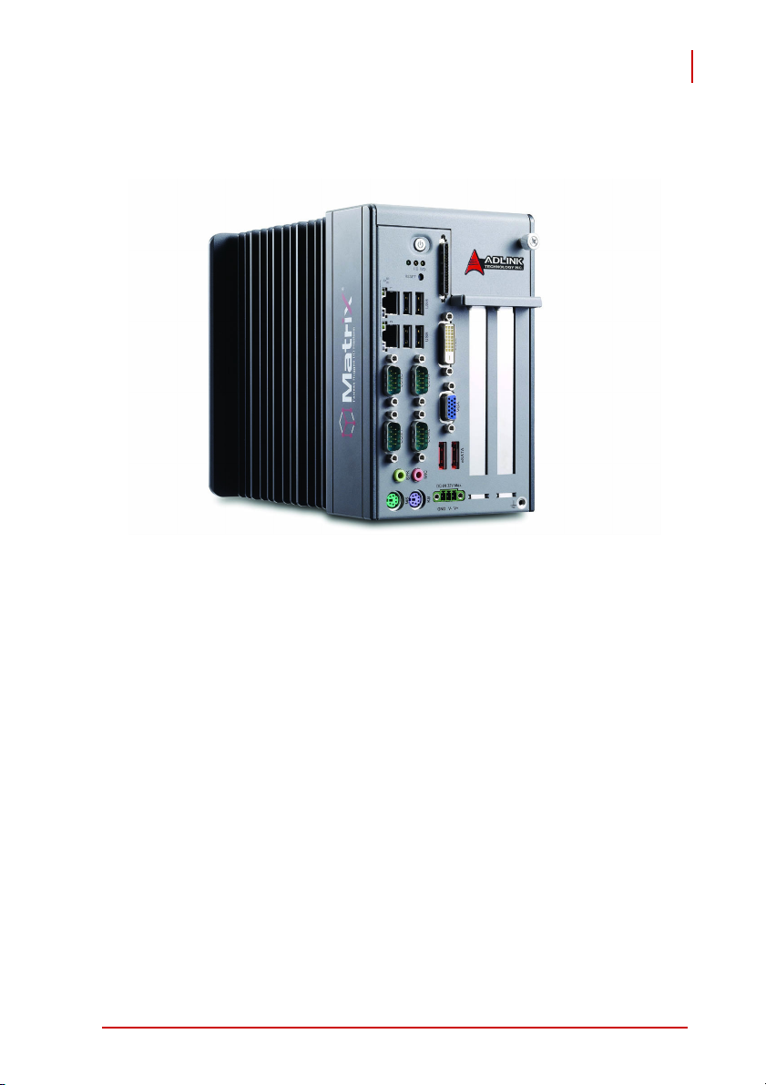
The Matrix MXC-4000 series is a fanless, embedded computer
based on the next generation Intel® Atom™ D510 dual-core processor to offer greater computing power for your applications. The
MXC-4000 inherits its exceptional fanless and cable-less design
from existing Matrix C series, with the addition of innovative features, such as an eSATA interface, an LVDS output, and a hotpluggable fan option.
The MXC-4000 series features an Intel® Atom™ D510 dualcore1.6 GHz processor to boostits performance to almost twice
that of the Atom™ N270 platform, while maintaining the same
overall power consumption. Its PCI and PCIe slots give you the
possibility to integrate off-the-shelf PCI/PCIe cards and develop a
configurable application platform. Built-in isolated DIO channels
are provided for general industrial control. Its LVDS output on the
front panel allows you to directly connect to a LCD panel. The
MXC-4000 series also provides two eSATA ports to enable the
capability of either expanding storage capacity or using hot-swappable SATA drives.
Introduction 1
Page 12

Matrix MXC-4000 Series
User’s Manual
Leveraging a reliable fanless and durable cable-less design, the
MXC-4000 series exhibits excellent dependability in harsh environments, where severe temperature variation and vibration may
exist.
The MXC-4000 series provides an optional hot-pluggable fan
module to dissipate heat generated within the system when high
power consumption PCI/PCIe cards are installed. This ingenious
mechanical design retains a cable-less structure which dramatically improves thermal stability when PCI/PCIe cards installed.
Combining a reliable design with more computing power and innovative features, the Matrix MXC-4000 series is the optimal choice
to base your rugged application system on.
2Introduction
Page 13

Matrix MXC-4000 Series
1.2 Specifications
Model Name MXC-4002D MXC-4011D
System Core
Processor Intel® Atom™ D510 1.66 GHz Dual-Core CPU
Chipset Intel® I/O Controller Hub 8 Mobile (ICH8-M)
VGA+LVDS display via DVI-D connector
Video
Memory 1 GB DDR2 667 MHz SODIMM module
I/O Interface
Expansion
Slots
Ethernet 2x GbE Ports (Intel® 82574L)
DI/O 12 DI + 12 DO
Serial Port
USB 4x USB 2.0 Ports
Audio 1x Mic-in and 1x Speaker-out
KB/MS 1x PS/2 Keyboard and 1x PS/2 Mouse
Power Supply
DC Input
AC Input Optional 80 W external AC-DC adapter for AC input
Storage Devices
SATA HDD On-board SATA Port for 2.5" HDD/SSD Installation
eS TATA
CompactFlash
Mechanical
Fan
Dimension 118 mm (W) x 219 mm (D) x 183 mm (H)
- Analog CRT, supports QXGA (2048 x 1536) resolution
- 18-bit LVDS output via DVI-D connector for LCD panel
2 PCI slots 1 x1 PCIe slot + 1 PCI slot
2x software-programmable RS-232/422/485 (COM1 &
COM2)
2x RS-232 (COM3 & COM4)
Built-in 9-32 V DC Input with Over-voltage Protection
3P Pluggable Connector with Latch (GND, V-, V+)
2x eSATA interface connectors for external storage
expansion
1x type II CompactFlash socket, supporting PIO and
DMA modes
Optional, hot-pluggable fan module for dissipating heat
generated by PCI/PCIe card
Table 1-1: Specifications
User’s Manual
Introduction 3
Page 14

Matrix MXC-4000 Series
User’s Manual
Weight 2.8 kg (6.16 lbs)
Mounting Wall-mount kit
Environmental
Operating
Temperature
Storage
Temperature
Humidity ~95% @ 40°C (non-condensing)
Vibration
Shock
Power
Consumption
(w/ 24 V DC
supply)
w/o FAN, w/o Card and w/o HDD: -10°C to 60°C
-40°C to 85°C
Operating, 5 Grms, 5-500 Hz, 3 Axes (w/CF or SSD)
Operating, 0.5 Grms, 5-500 Hz, 3 Axes (w/HDD)
Operating, 50 Grms, Half-sine 11 ms duration (w/CF or
SSD)
0.72 W (Power Off), 12.96 W (System Idle), 35.04 W
(System Full Load)
Table 1-1: Specifications
4Introduction
Page 15

Matrix MXC-4000 Series
User’s Manual
1.3 Unpacking Checklist
Before unpacking, check the shipping carton for any damage. If
the shipping carton and/or contents are damaged, inform your
dealer immediately. Retain the shipping carton and packing materials for inspection. Obtain authorization from your dealer before
returning any product to ADLINK.
Check if the following items are included in the package.
MXC-4000
X MXC-4000 controller
X Wall-mount bracket
X Screw pack for the wall-mounting and HDD
X User’s manual
X ADLINK All-in-One DVD
Note: The package contents of OEM versions may vary
depending on customer requests. The assigned
controller and/or peripheral modules may be pre-installed
and shipped with the chassis. Inquire with your dealer for
additional information on these options.
Introduction 5
Page 16

Matrix MXC-4000 Series
User’s Manual
This page intentionally left blank.
6Introduction
Page 17
Matrix MXC-4000 Series
User’s Manual
2 System Description
This section describes the appearance and connectors of the
MXC-4000 controller, including chassis dimension, front panel
connectors, and internal IO connectors.
2.1 Mechanical Drawings
All dimensions shown are in mm.
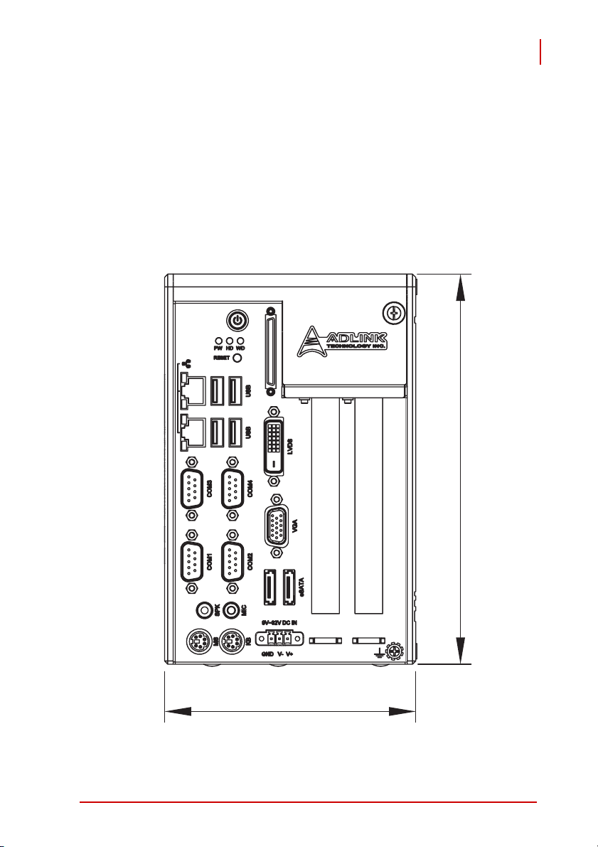
2.1.1 Front View
182.8
117.8
System Description 7
Page 18
Matrix MXC-4000 Series
User’s Manual
2.1.2 Rear View
4
8System Description
Page 19
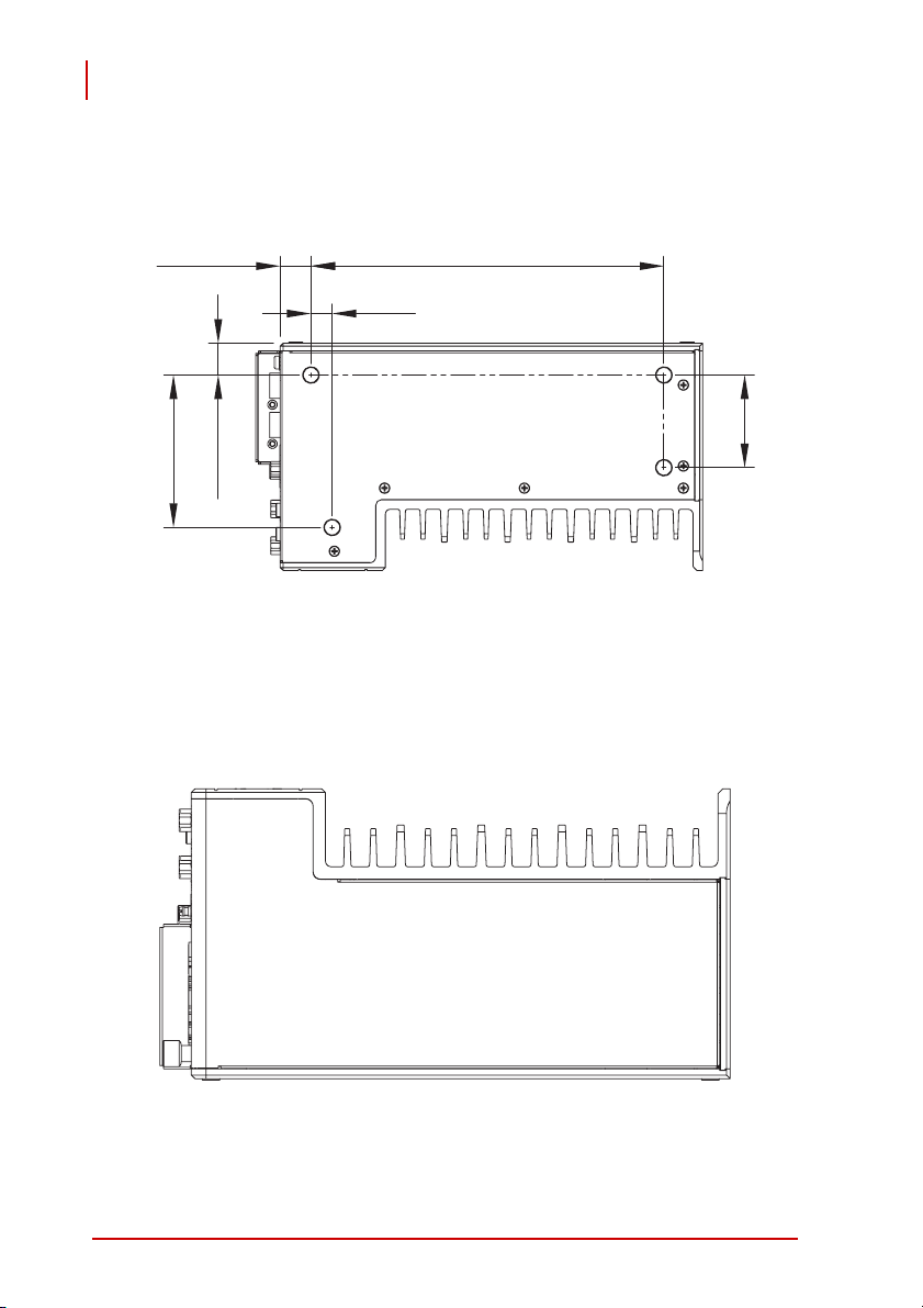
2.1.3 Side View (Left)
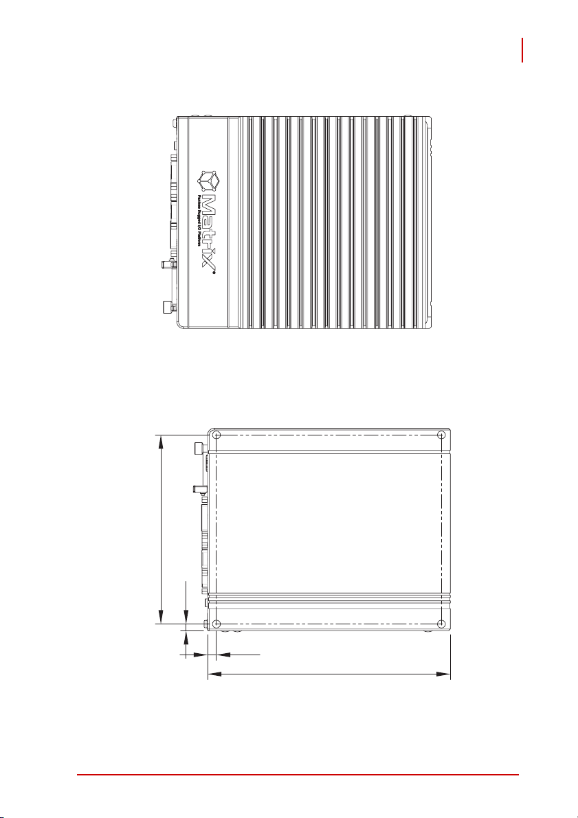
2.1.4 Side View (Right)
Matrix MXC-4000 Series
User’s Manual
170.8
6
8
219.1
System Description 9
Page 20
Matrix MXC-4000 Series
User’s Manual
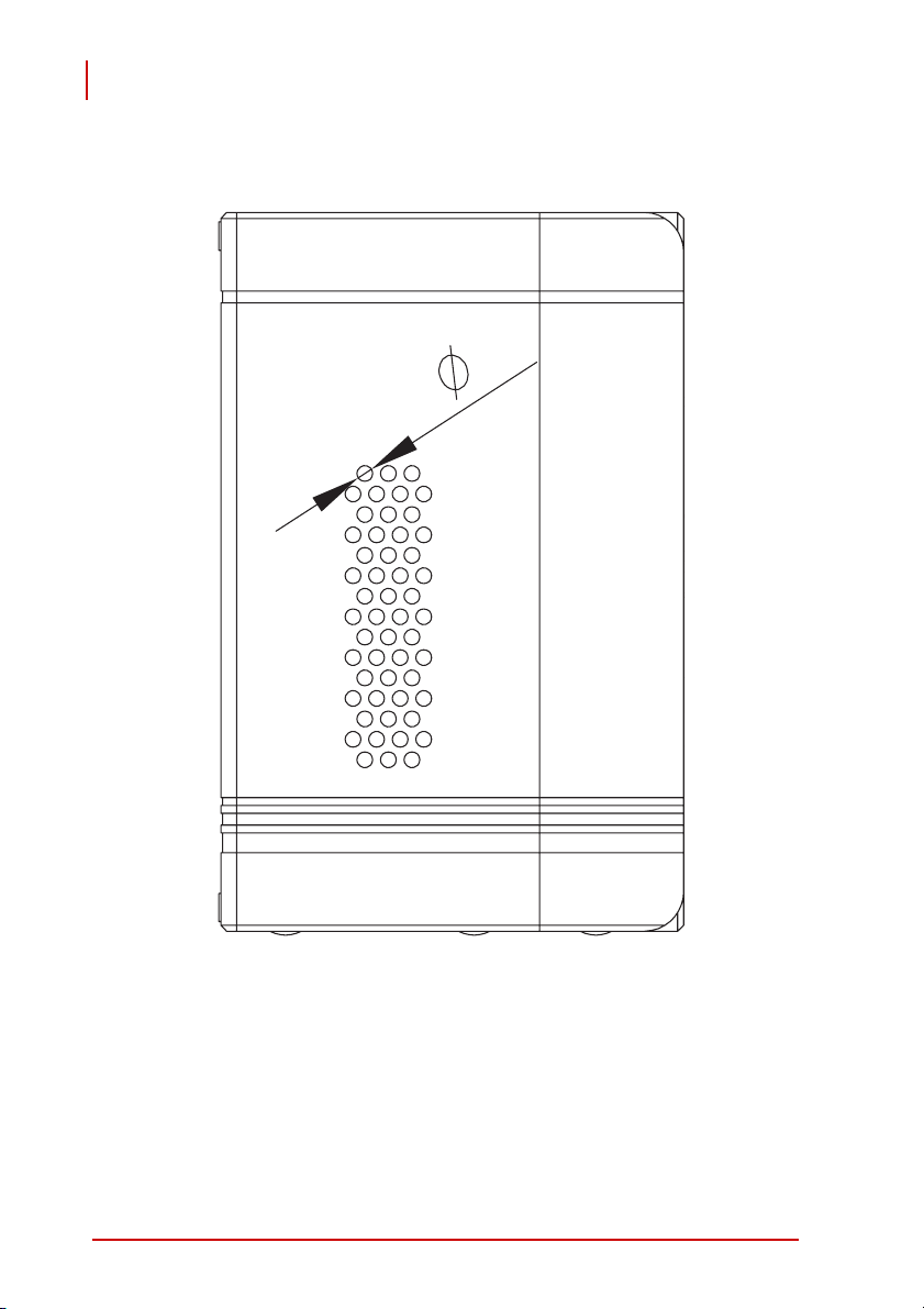
2.1.5 Bottom View
79
16.5
2.1.6 Top View
183.115.9
11
48
10 System Description
Page 21
Matrix MXC-4000 Series
User’s Manual
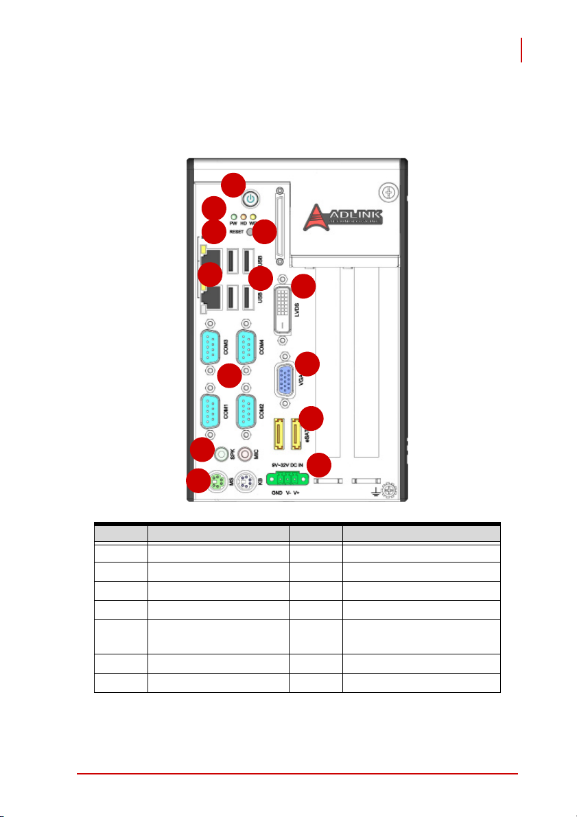
2.2 Front Panel I/O Connectors
The MXC-4002D/4011D controller has the same I/O connector
configuration on the front panel. This section describes functions
of these I/O connectors.
A
B
C D
E
F
G
I
H
J
K
M
L
Symbol Function Symbol Function
A Power button H COM ports
B LED indicators I VGA connector
C Reset button J eSATA ports
D Digital I/O connector K Audio jacks
E Dual Gigabit Ethernet
ports
F USB2.0 ports M DC power input connector
G LVDS Connector
Table 2-1:
MXC-4002D/4011D Connectors
L PS2 keyboard & mouse
System Description 11
Page 22

Matrix MXC-4000 Series
User’s Manual
2.2.1 Power Button
The power button is a non-latched push button with a blue LED
indicator. The system is turned on when button is pressed, and the
power LED is also illuminated. To shut down the system, you can
issue shutdown command via the operating system or just press
the power button. If the system halts, you can also press the button for 5 seconds to force system shutdown.
2.2.2 LED Indicators
There are three LED indicators on the front panel. The following
table describes the color and function of the LED indicators.
LED indicator Color Description
Watchdog (WD) Yellow Indicates the status of watchdog timer.
When the watchdog timer is started, the
LED is flashing. And when the timer is
expired, the LED is on.
Hard disk drive (HD) Orange Indicates tthe operating state of HDD.
When the SATA hard drive or internal CF
card is active, the LED indicator is flashing.
Power LED (PW) Green Indicates the status of the power.
When the power is presed, the LED will
be on.
Table 2-2: LED Indicators
2.2.3 Reset Button
The reset button is used to perform a hard reset of the MXC4002D/4011D controller.
12 System Description
Page 23

Matrix MXC-4000 Series
User’s Manual
2.2.4 Digital I/O Connector
The MXC-4002D/4011D controller features on-board isolated digital I/O circuit and has a 68-pin VHDCI (Very High Density Cable
Interconnect) connector on the front panel. The on-board digital I/
O card supports the following features:
X 12-CH Isolated DI
Z Logic high: 5 to 24 V
Z Logic low: 0 to 1.5 V
Z Input resistance: 2.4 k @ 0.5 W
Z Isolation voltage: 1000 V
12-CH Isolated DO
X
Z Output Type: open drain power MOSFET driver
Z 250 mA for all channels @ 60°C, 100% duty
Z Supply voltage: 5 to 35 V
Isolation voltage: 1000 V
Z
Data transfers: programmed I/O
Z
RMS
DC
RMS
System Description 13
Page 24

Matrix MXC-4000 Series
User’s Manual
(1) VDD (24) IDI_1L (47) EOGND
(
6
8
)
(
6
7
)
(2) EOGND (25) IDI_0H (48) IDO_10
(3) IDO_7 (26) IDI_0L (49) EOGND
3
4
(
)
3
3
(
)
(4) EOGND (27) IDI_11 (50) IDO_9
(5) IDO_6 (28) IGND (51) EOGND
(6) EOGND (29) IDI_10 (52) IDO_8
(7) IDO_5 (30) IGND (53) IDI_7H
(8) EOGND (31) IDI_9 (54) IDI_7L
(9) IDO_4 (32) IGND (55) IDI_6H
(10) EOGND (33) IDI_8 (56) IDI_6L
(11) IDO_3 (34) IGND (57) IDI_5H
(12) EOGND (35) VDD (58) IDI_5L
(13) IDO_2 (36) ISO5V (59) IDI_4H
(14) EOGND (37) EOGND (60) IDI_4L
(15) IDO_1 (38) NC (61) NC
(16) EOGND (39) EOGND (62) IGND
(17) IDO_0 (40) NC (63) NC
(18) EOGND (41) EOGND (64) IGND
(19) IDI_3H (42) NC (65) NC
(20) IDI_3L (43) EOGND (66) IGND
(
3
(
6
)
(
3
5
)
2
)
(
1
)
(21) IDI_2H (44) NC (67) NC
(22) IDI_2L (45) EOGND (68) IGND
(23) IDI_1H (46) IDO_11
Table 2-3: Digital I/O Connector
Legend:
X IDI_n: Isolated digital input channel #n.
X IDO_n: Isolated digital output channel #n.
X IDI_nH: High input of isolated differential DI channel #n.
X IDI_nL: Low input of isolated differential DI channel #n.
X EOGND: Ground return path of isolated output channels.
X VDD: Power input signal for fly-wheel diode of DO chan-
nels.
14 System Description
Page 25

Matrix MXC-4000 Series
User’s Manual
2.3 Operating Principles
2.3.1 Isolated Digital Input
Isolated digital input utilizes an open collector transistor structure,
with input voltage range of 0 V to 24 V and input resistance of 2.4K
Ω. Connection between external signals and the MXC-4002D/
4011D controller is as shown.
Note: The common input junction can be common ground or
common power, based on the applied environment, such
that digital input can be either a current source or current
sink.
Figure 2-1: Isolated Input Connection
System Description 15
Page 26

Matrix MXC-4000 Series
User’s Manual
2.3.2 Isolated digital Output
Common ground connection of isolated digital output and common
power connection of isolated digital output are shown.
When isolated digital output enters an “ON” state, sink current is
conducted through the transistors. When an “OFF” state is
entered, there is no current through the transistors.
Note: When the load is of an “inductance nature” such as a
relay, coil or motor, the VDD pin must be connected to an
external power source, with the extra connection utilized
for the ‘fly-wheel diode’ to form a current-release closed
loop, by which the transistors are protected from high
reverse voltage generated by the inductance load when
the output is switched from “ON” to “OFF”.
Figure 2-2: Common Ground Connection
16 System Description
Page 27

Matrix MXC-4000 Series
Figure 2-3: Common Power Connection
User’s Manual
System Description 17
Page 28

Matrix MXC-4000 Series
User’s Manual
2.4 Gigabit Ethernet (WG82574L)
The MXC-4002D/4011D controller has two GbE ports on the front
panel by Intel WG82574L Gigabit Ethernet controller.
The Ethernet controller supports the following features:
X x1 PCI Express® interface with 2.5 GHz signaling
X PCIe* advanced extensions
X Message signaled interrupts
X TCP Segmentation/Transmit Segmentation Offloading
(TSO) support
X IEEE 802.3x and 802.3z compliant flow control support
X IEEE 802.1q support
X Compliant with 1 Gb/s Ethernet IEEE 802.3x PHY specifica-
tions
X Automatic MDI/MDIX crossover at all speeds
X ACPI 2.0 specification
X Full wake-up support
X Fully integrated ASF 2.0 functionality with on-chip μc
X SMBus 2.0 master interface for ASF functionality
X Preboot eXecution Environment (PXE) flash interface sup-
port
18 System Description
Page 29

Matrix MXC-4000 Series
User’s Manual
Active/Link LED
LED Color Status Description
Off Ethernet port is disconnected
Yel low
ON Ethernet port is connected and no data transmission
Flashing
Ethernet port is connected and is transmitting/receiving data.
Table 2-4: Active/Link LED
Speed LED
LED Color Status Description
Off 10 Mbps
Green/Orange
Green 100 Mbps
Orange 1000 Mbps
Table 2-5: Speed LED
2.4.1 USB 2.0 connectors
The MXC-4002D/4011D controller provides four USB 2.0 ports in
Type A USB connectors on the front panel. All USB ports are compatible with high-speed, full-speed and low-speed USB devices.
The MXC-4000 series supports multiple boot devices, including
USB flash drive, USB external hard drive, USB floppy, USB CDROM and etc. The boot priority and boot device can be configured
in BIOS. Please refer to section 4.1.5 for details.
System Description 19
Page 30

Matrix MXC-4000 Series
User’s Manual
2.4.2 LVDS Connector
The MXC-4002D/4011D controller provides LCD panel function in
the LVDS connector on the front panel.
The MXC-4000 series supports only 18-bit one channel panel
type.
1 C_LVD_A_DATA2_N14 VCC_FPD
2 C_LVD_A_DATA2_P15 DGND
3 DGND 16 C_LDDC_CLK
4 C_LVD_EN 17 C_LVD_A_DATA0_
N
5 D12V_EXT 18 C_LVD_A_DATA0_
P
6 C_L_BRIGHTNESS 19 DGND
7 C_LBKLT_EN_DELAY20 C_LCD_PID1_R
8 C_LDDC_DATA 21 C_LCD_PID0_R
9 C_LVD_A_DATA1_N22 DGND
10 C_LVD_A_DATA1_P23 C_LVD_A_CLK_P
11 DGND 24 C_LVD_A_CLK_N
12 C_DBL_CLK 25 CHGND
13 DGND 26 CHGND
Figure 2-4: LVDS Connector
2.4.3 COM Ports
The MXC-4002D/4011D controller provides four COM ports in the
form of D-Sub 9P connectors. COM1 and COM2 ports support
RS-232/RS-422/RS-485 by BIOS selection, while COM3 and
COM4 ports support RS-232 function only. Please refer to section
20 System Description
Page 31

Matrix MXC-4000 Series
User’s Manual
4.1.2.3 for the selection of setting RS-232/422/485 by BIOS of
COM1 and COM2 ports.
PIN
RS-232 RS-422 RS-485
1 DCD# TXD422- 485DATA-
2 RXD# TXD422+ 485DATA+
3 TXD# RXD422+
4 DTR# RXD422-
5GND
6DSR#
7RTS#
8CTS#
9RI#
Signal Name
System Description 21
Page 32

Matrix MXC-4000 Series
User’s Manual
2.4.4 VGA Connector
The D-sub 15-pin VGA connector is used to connect your MXC4002D/4011D controller to a monitor. The MXC-4000 series supports only analog (VGA) monitors.
PIN Signal Name
1RED
2 GREEN
3BLUE
4NC
5DGND
6VGA_EN
7DGND
8DGND
9 VGAPWR
10 DGND
11 N C
12 SD_DATA
13 HSYNC_CN
14 VSYNC_CN
15 SD_CLK
16 CHGND
17 CHGND
Table 2-6: VGA Connector
22 System Description
Page 33

Matrix MXC-4000 Series
User’s Manual
2.4.5 E-SATA Connectors
The MXC-4002D/4011D controller has two E-SATA ports connectors on the front panel. The MXC-4000 series supports external
storage expansion.
PIN Signal Name
1DGND
2 SATA1_TXP
3 SATA1_TXN
4DGND
5 SATA1_RXN
6 SATA1_RXP
7DGND
8DGND
9 SATA2_TXP
10 SATA2_TXN
11 DG ND
12 SATA2_RXN
13 SATA2_RXP
14 DGND
15 CHGND
16 CHGND
17 CHGND
18 CHGND
Table 2-7: E-SATA Connectors
System Description 23
Page 34

Matrix MXC-4000 Series
User’s Manual
2.4.6 Audio Jacks
The MXC-4002D/4011D controller implements Intel High Definition
audio using Realtek ALC262 chip. The HD audio supports up to
24-bit, 192 Kbps high quality headphone/speaker output and
microphone input. Users can access the audio jacks on the front
panel of MXC-4000 series. The pink jack is for microphone input,
and the green jack is for speaker output.
Color Signal Name
GREEN LINE OUT
PINK MIC IN
Table 2-8: Audio Jacks
2.4.7 Keyboard & Mouse PS2 Connectors
The MXC-4002D/4011D controller provides connectors for connecting PS2 keyboard and mouse. The green connector is for PS/
2 mouse and the purple one is for PS/2 key-board.
PIN Signal Name
1 KBDATA
2NC
3DGND
4 KBVCC
5 KBCLK
6NC
7MSDATA
8NC
9DGND
10 KBVCC
11 MSCL K
12 NC
Table 2-9: Keyboard & Mouse PS2 Connectors
24 System Description
Page 35

Matrix MXC-4000 Series
User’s Manual
2.4.8 Power Input Connector
The DC power input connector of the MXC-4002D/4011D controller consists of three pins: V+, V- and chassis ground from right to
left respectively. V+ and V- pins are for DC power input and chassis ground pin allows connect the chassis to ground for better
EMC compatibility. The DC power input of MXC-4000 series
allows a voltage input from 9 VDC to 32 VDC. The MXC-4000
series also features the under/over voltage input protection.
The system will automatically shut off when input voltage is too
low (under 7.5 V) or too high (over 34 V).
PIN Signal Name
1 GND(CHGND)
2 V-(DGND)
3 V+(DC_IN)
Table 2-10: Power Input Connector
System Description 25
Page 36

Matrix MXC-4000 Series
User’s Manual
2.5 Internal I/O Connectors
The section describes the internal I/O connectors of the MXC4000 series. MXC-4002D and MXC- 4011D have the same internal I/O connectors. The figure showed below is what’s inside the
MXC-4000 series.
B
A
This page intentionally left blank.
Symbol Function
A CompactFlash Socket
B FAN connector
C SATA connector
D Clear CMOS button
Table 2-11: Internal I/O Connectors
D
C
26 System Description
Page 37

Matrix MXC-4000 Series
User’s Manual
2.5.1 CompactFlash Socket
The internal CompactFlash socket is connected to chipset via IDE
interface, and can be used as an alternative storage device for
system installation. If want to boot up the MXC-4002D/4011D controller via a CF card with OS installed. Due to the nature of IDE
interface, the CF card is not hot-pluggable and must be installed
before system power on. Please refer to section 3.3 for the illustration of installing a CF card.
2.5.2 Fan Connector
The MXC-4002D/4011D controller provides a insert the optional
fan module by gently slide it into the fan connector.
PIN Signal Name
1 D12V
2FDO
3PWM
4GND
Table 2-12:
Fan Connector
Note: This USB-like connector is not a USB port and is only for
connecting the fan.
2.5.3 SATA Connector
The MXC-4002D/4011D controller provides a SATA Gen.1 port.
The SATA host controller supports two modes of operation, the
legacy mode using I/O space and AHCI mode using memory
space. This SATA connector is designed for installing a 2.5” hard
disk drive or solid state disk (SSD). The HDD or SSD must be
installed into SATA connector with a specific bracket mounted on
the chassis. Please refer to section 3.1 for the illustration of installing a 2.5” hard disk drive or SSD.
System Description 27
Page 38

Matrix MXC-4000 Series
User’s Manual
2.5.4 Clear CMOS Button
When encountering the abnormal condition that causes the MXC4002D/4011D controller failed to boot, can try to clear the BIOS
content stored in CMOS and restore to the default setting. To clear
CMOS, just press the button and hold on for 1~2 second then
release it. After doing that, the CMOS will restore to the factory
default setting.
28 System Description
Page 39

Matrix MXC-4000 Series
User’s Manual
3 Getting Started
This chapter demonstrates how to install the hard disk drive, PCI/
PCIe card and CompactFlash card into system. Additional COM
ports jumper settings and and the MXC-4000 series wall-mount
installation are also discussed.
3.1 Installing a hard disk drive
Before installing a hard disk drive, you should remove the top
cover of chassis first. Please follow the instruction below.
1. Unscrew the screw on the front panel by hand or a
screwdriver.
Getting Started 29
Page 40

Matrix MXC-4000 Series
User’s Manual
2. Hold the screw and pull it toward to your body side.
30 Getting Started
Page 41

Matrix MXC-4000 Series
User’s Manual
3. After removing the top cover, please use a screwdriver
to unscrew two screws on the top side.
Getting Started 31
Page 42

Matrix MXC-4000 Series
User’s Manual
4. Place the chassis upside down and unscrew another two
screws on the bottom side.
5. Pull the HDD bracket up.
32 Getting Started
Page 43

Matrix MXC-4000 Series
User’s Manual
6. Find the 4 M3 screws as accessories in the package.
Fasten them to fix a 2.5” HDD or SSD to the bracket.
Getting Started 33
Page 44

Matrix MXC-4000 Series
User’s Manual
7. Gently push the HDD/SSD bracket down to the SATA
connector on the PCB.
8. Reverse Step 3 and 4 to fasten the 4 screws.
9. Put the top cover back, and then fasten the thumbscrew.
34 Getting Started
Page 45

Matrix MXC-4000 Series
User’s Manual
3.2 Installing PCI/PCIe card
Please follow steps 1-2 in section 3.1 to remove the top cover
before installing a PCI/PCIe card.
1. Insert your PCI or PCIe card to the PCI/PCIe slot. Note
that there is a joint point on the lower side. Please make
sure that the lower edge of your PCI/PCIe card is placed
into the joint point.
Getting Started 35
Page 46

Matrix MXC-4000 Series
User’s Manual
2. After installing your PCI/PCIe card, you can use the
hold-on bars included with the MXC-4000 series to hold
your card.
36 Getting Started
Page 47

Matrix MXC-4000 Series
User’s Manual
3. Adjust the position of hold-on bar to make it hold you
card firmly. And tighten the screw to fix the hold-on bar.
4. Replace the top cover and fasten the thumbscrew.
Getting Started 37
Page 48

Matrix MXC-4000 Series
User’s Manual
3.3 Installing a CF Card
The MXC-4000 series controller provides an internal CompactFlash socket to accommodate a CF card as a replacement of hard
disk drive. Please follow steps 1-2 in section 3.1 to remove the top
cover before installing a CF card.
1. Align your CF card with the guide of CF socket.
38 Getting Started
Page 49

Matrix MXC-4000 Series
User’s Manual
2. Gently push your CF card down to make it firmly
attached to the internal CF socket.
3. Use the spacer supports fromaccessories in the pack-
age, to prevent the CF card from coming loose.
4. Replace the top cover and fasten the thumbscrew.
Getting Started 39
Page 50

Matrix MXC-4000 Series
User’s Manual
3.4 Plug-in DC power
Note: Before plugging DC power into the MXC-4000
seriescontroller, please make sure you have correct
voltage and polarity for your DC input. An improper input
voltage or polarity will cause system damage.
The DC power input connector of the MXC-4000 controller consists of three pins, V+, V- , and chassis ground from right to left
respectively. The DC power input accepts an input voltage from 9
VDC to 32 VDC. Connect the DC power as shown in the figure
showed below. Two screws of the plug should be fastened to prevent the plug from becoming loose.
40 Getting Started
Page 51

Matrix MXC-4000 Series
User’s Manual
3.5 Mounting MXC4000 Series Controller
The MXC-4000 series controller is shipped with wall-mount brackets. You can use the wall-mount brackets and accessory screws to
mount the MXC-4000 controller on the wall.
The procedures of mounting MXC-4000 series are illustrated step
by step below:
1. Remove four plastic pads in the four corners.
Getting Started 41
Page 52

Matrix MXC-4000 Series
User’s Manual
2. You can find two wall-mount brackets and four M4
screws in the accessory box shipped with the controller.
Fasten four screws to fix the brackets to the chassis.
3. The final assembly is shown below. You can mount the
MXC-4000 controller on the wall via proper screw holes,
as shown in the mechanical drawings.
42 Getting Started
Page 53

84.0
Matrix MXC-4000 Series
User’s Manual
182.0
84.0
233.1
247.1
Figure 3-1: Wall-Mount Mechanical Drawing
7.2
5.2
108.0
168.0
Figure 3-2: Fixed Wall-Mount Hole
Getting Started 43
Page 54

Matrix MXC-4000 Series
User’s Manual
Figure 3-3: Removable Wall-Mount Hole
25.2
5.2
10.0
44 Getting Started
Page 55

Matrix MXC-4000 Series
User’s Manual
4 BIOS Settings and Driver Installation
4.1 BIOS Setting
The Basic Input/Output System (BIOS) is a program that provides
a basic level of communication between the processor and peripherals. In addition, the BIOS also contains codes for various
advanced features applied to the MXC-4000 series controller. The
BIOS setup program includes menus for configuring settings and
enabling features of MXC-4000 series. Most users do not need to
use the BIOS setup program, as the MXC-4000 series controller
ships with default settings that work well for most configurations.
In this section, BIOS options are illistrated.
Warning: Changing BIOS settings may lead to incorrect
controller behavior and possibly an unbootable
controller. If this happens, follow the instructions in
Section 2.4.4 to clear CMOS and then restore the
default settings. In general, do not change a BIOS
setting unless you are absolutely certain of what it
does.
4.1.1 Main
4.1.1.1 System Time/System Date
Use this option to specify the system time and date. Highlight System Time or System Date using the up or down <Arrow> keys.
Enter new values using the keyboard then press <Enter> key.
Press the < Tab > key to move between fields. The date must be
entered in MM/DD/YY format. The time is entered in HH:MM:SS
format.
Note: The time is in 24-hour format. For example, 5:30 A.M.
appears as 05:30:00, and 5:30 P.M. as 17:30:00.
BIOS Settings and Driver Installation 45
Page 56

Matrix MXC-4000 Series
User’s Manual
4.1.2 Advanced
4.1.2.1 CPU Configuration
Hyper Threading Technology
This option allows you to Enable/Disable Hyper-Threading
Technology.
Intel® SpeedStep
TM
Tech
This option enables or disables Intel SpeedStep technology.
4.1.2.2 IDE Configuration
ATA/IDE Configuration
This option specifies whether the IDE channels should be initialized in Compatible Mode or Enhanced Mode. The settings
are Disabled, Compatible and Enhanced. The default option is
Compatible.
Configure SATA as
Show this item when select ATA/IDE Configuration to
Enhanced. The options are IDE, AHCI and RAID.
Primary IDE Master
Press < Enter > to configure the first device (master) on IDE
interface.
Primary IDE Slave
Press < Enter > to configure the second device (slave) on IDE
interface.
Secondary IDE Master
Press < Enter > to configure the first device (master) on secondary IDE interface.
Secondary IDE Slave
Press < Enter > to configure the second device (slave) on secondary IDE interface.
46 BIOS Settings and Driver Installation
Page 57

Matrix MXC-4000 Series
User’s Manual
Third IDE Master
Press < Enter > to configure the first device (master) on IDE
interface.
Third IDE Slave
Press < Enter > to configure the second device (slave) on IDE
interface.
4.1.2.3 SuperIO Configuration
Serial Port1/ Port2/ Port3/ Port4 Address
These four options specify the base I/O port address of serial
port1 to serial port4.
Note: Do not set the same value for different serial ports to
avoid resource conflict.
COM1 Mode/COM2 Mode
Software configure the COM1 and COM2 port mode, options
are RS232,RS422 and RS485.
4.1.2.4 Hardware Health Configuration
The hardware health option allows users to monitor hardware status including CPU temperature, system temperature, and system
voltages (Vcore, +5V, +3.3V, +12V, +1.8V, 5VSB, VBAT).
BIOS Settings and Driver Installation 47
Page 58

Matrix MXC-4000 Series
User’s Manual
4.1.2.5 ACPI Configuration
Suspend Mode
This setting specifies either S1 (POS) or S3 (STR) system suspend mode. The Optimal and Fail-Safe Default setting is S3
(STR).
Option Description
Power On Suspend - Maintain current system status,
such as power supply and memory context, except for
S1 (POS)
S3 (STR)
Auto
CPU is not executing instructions. Devices that can
wake-up the system can cause CPU to continue execute
from where it left off.
Suspend to RAM - System enters a low power state
instead of completely shut-off. Standby power and power
supply for memory are maintained.
Depends on OS, OS automatically selects suspend mode
it supports.
Table 4-1: Suspend Mode
Energy Lake Feature
Enable or disable Intel Energy Lake Feature, Quick resume
technology.
USB Device Wakeup From S3/S4
Enable or disable USB Device, typically USB keyboard or USB
mouse to wake up system from S3 or S4.
High Performance Event Timer
Enable or disable HPET feature.
48 BIOS Settings and Driver Installation
Page 59

Matrix MXC-4000 Series
User’s Manual
4.1.2.6 AHCI Configuration
AHCI BIOS Support
Enable or disable Advanced Host Controller Interface support.
AHCI Port0
Press < Enter > to configure the AHCI Port0 device on AHCI
interface.
AHCI Port1
Press < Enter > to configure the AHCI Port1 device on AHCI
interface.
AHCI Port2
Press < Enter > to configure the AHCI Port2 device on AHCI
interface.
BIOS Settings and Driver Installation 49
Page 60

Matrix MXC-4000 Series
User’s Manual
4.1.2.7 USB Configuration
Legacy USB Support
Legacy USB Support also refers to USB mouse and keyboard
support. Normally if this option is not enabled, attached USB
mouse or keyboard will not be available until a USB compatible
operating system fully boots up with USB drivers loaded. With
this option enabled, attached USB mouse or keyboard is
usable even when no USB drivers loaded.
Option Description
Disabled
Enabled
Auto
Set this value to prevent the use of any USB device
during system boot or in DOS environment.
Set this value to allow the use of USB devices during system boot or in DOS environment.
This option automatically detects USB keyboard or
mouse and if found, allows the usage during system
boot or in DOS environment.
Table 4-2: Legacy USB Support
USB 2.0 Controller Mode
The USB 2.0 Controller Mode configures the data rate of the
USB port. Available options are FullSpeed (12 Mbps) and HiSpeed (480 Mbps).
BIOS EHCI hand-off
This option provides a workaround for OSes without ECHI
hand-off support. The change of EHCI ownership should be
claimed by the EHCI driver.
USB Mass Storage Device Configuration
This is a submenu for configuring the USB Mass Storage Class
Devices which are in use on the USB ports found by BIOS.
Emulation Type can be set according to the type of attached
USB mass storage device(s). If set to Auto, USB devices less
than 530MB will be emulated as Floppy and those greater than
530MB will remain as hard drive. The Forced FDD option can
be used to force a hard disk type drive to boot as FDD (Ext. ZIP
Drive).
50 BIOS Settings and Driver Installation
Page 61

Matrix MXC-4000 Series
User’s Manual
4.1.3 Chipset
4.1.3.1 North Bridge Configuration
DRAM Frequency
Specify DRAM frequency. You can specify whether let BIOS set
DRAM frequency automatically or configure it manually (400
MHz or 533 MHz).
Configure DRAM Timing by SPD
Specify Enable to allow the timing setting of DRAM to be configured from SPD or Disable to configure it manually.
Initiate Graphic Adapter
Select which graphics controller to use as the primary boot display device. Support IGD, PCI/IGD.
Internal Graphics Mode Select
Specify the size of system memory used by internal graphics
device. 8MB is recommended.
BIOS Settings and Driver Installation 51
Page 62

Matrix MXC-4000 Series
User’s Manual
DVMT Mode Select
Dynamic Video Management Technology (DVMT) allows additional system memory to be dynamically allocated in operating
system for graphics usage. Once the application is closed, the
allocated memory is released and is then available for system
usage. DVMT ensures a solid balance between system performance and graphics performance.
Option Description
Fixed Mode
DVMT Mode
The graphics driver reserves a fixed portion of the
system memory as graphics memory.
The graphics driver dynamically allocates system
memory for graphics usage, according to system and
application demands.
Table 4-3: DVMT Mode Select
Boot Display Device
Select system boot display device, options are VGA or
VGA+LVDS. The default option is VGA+LVDS.
Flat Panel Type
Select the display resolution of flat panel, supported options
are “800X600” and “1024X768”.
52 BIOS Settings and Driver Installation
Page 63

Matrix MXC-4000 Series
User’s Manual
4.1.3.2 South Bridge Configuration
USB Function
Specify the number of USB ports enabled in Matrix controller.
The default value is 8 USB ports.
USB 2.0 Controller
This option depends on the setting of USB Function. If USB
Function is set to Disabled, this option will have no effect.
Enabled will open USB 2.0 functionality to all USB ports.
Restore on Power Loss
Determines what state the computer enters when power is
restored after a power loss. The options for this value are Last
State, Power On and Power Off.
Option Description
Power Off
Power On
Last State
The Matrix controller remains off when external DC
power is supplied.
The Matrix controller is turn on when external DC
power is supplied. You can specify this option to mimic
the AT power behavior, and use an external switch to
control the on/off of Matrix controller.
If encountering a power loss, the Matrix controller
resumes to the previous on/off state when external
power is normally supplied.
Table 4-4: Restore on Power Loss
BIOS Settings and Driver Installation 53
Page 64

Matrix MXC-4000 Series
User’s Manual
4.1.4 Security
The Security setup menu provides both a Supervisor and a User
password. If you use both passwords, the Supervisor password
must be set first.
To uninstall the passwords, you can simply set a NULL password.
Change Supervisor Password
Select Change Supervisor Password and press < Enter >.
And enter your password in the appearing message box as
prompted. The password is stored in NVRAM after setup completes.
User Access Level
This option appears after specifying Supervisor password, and
allows you to specify the access level for users.
Option Description
No Access Users are not allowed to access the BIOS setting.
View Only
Limited Users are allowed only to change limited items in BIOS.
Full Access
Users are allowed to view BIOS setting but not allowed
to change it.
Users are allowed to access and change all setting
items in BIOS.
Table 4-5: User Access Level
Change User Password
Select Change User Password and press < Enter >. And
enter your password in the appearing message box as
prompted. The password is stored in NVRAM after setup completes.
Password Check
This option appears after specifying Supervisor password.
Option Description
Setup Check password when entering BIOS setup.
Always Check password when system booting.
54 BIOS Settings and Driver Installation
Page 65

Matrix MXC-4000 Series
User’s Manual
4.1.5 Boot
4.1.5.1 Boot Settings Configuration
Quick Boot
Option Description
Disabled Specify BIOS to perform all POST tests.
Enabled Specify BIOS to skip certain POST test to boot faster.
Quiet Boot
Option Description
Disabled Specify BIOS to display POST messages.
Enabled Specify BIOS to display the OEM logo.
Bootup Num-Lock
Specify whether the Number Lock is on or off after power-on.
Wait for ‘F1’ If Error
If this option is specified as Disabled, BIOS does not wait for
users to press the <F1> key if any error occurs.
Hit ‘DEL’ Message Display
If this option is specified as Enabled, the system displays the
message "Press DEL to run Setup during POST"
Intel 82574L PXE ROM
Disabled/Enabled the Intel 82574L PXE ROM to close/open
Intel LAN PXE function.
BIOS Settings and Driver Installation 55
Page 66

Matrix MXC-4000 Series
User’s Manual
4.1.5.2 Boot Device Priority
Specify the priority of boot devices. All installed boot devices are
detected during POST and displayed on the screen. You can refer
to the following steps to specify different boot device.
Boot from a SATA hard drive
1. Select Hard Disk Drives and press Enter.
2. Your SATA hard drive is displayed with its identification
string. Specify it as 1st Drive.
3. Go back to upper level and select your SATA hard drive
in 1st Boot Device.
Boot from CF card
1. Select Hard Disk Drives and press Enter.
2. Your CF card is displayed with its identification string.
Specify it as 1st Drive.
3. Go back to upper level and select your CF card in 1st
Boot Device.
Boot from USB CD/DVD drive
1. Select USB Drives and press Enter.
2. Your CD/DVD drive is displayed with its identification
string. Specify it as 1st Drive.
3. Go back to upper level and select your CD/DVD drive in
1st Boot Device.
Boot from USB Flash disk
1. Select USB Drives and press Enter.
2. Your USB flash disk is displayed with its identification
string. Specify it as 1st Drive.
3. Go back to upper level and select your USB flash disk in
1st Boot Device.
56 BIOS Settings and Driver Installation
Page 67

Matrix MXC-4000 Series
User’s Manual
4.1.6 Exit
Save Changes and Exit
When you finish BIOS setting, please select this option to save
all changes and reboot the system to make new setting takes
effect.
Discard Changes and Exit
Select this option to discard all changes and exit BIOS setup..
Discard Changes
Select this option to discard all changes without exiting BIOS
setup..
Load Optimal Defaults
Select this option to set all BIOS options to a complete set of
default setting. The Optimal setting is designed for maximum
system performance, but may not work best for all computer
applications. In particular, do not use the Optimal Setup options
if your computer encounters system configuration problems.
Load Failsafe Defaults
Select this option to set all BIOS options to a complete set of
default setting. The Failsafe setting is designed for maximum
system stability, but not maximum performance. Select the
Fail-Safe Setup options if your computer encounters system
configuration problems.
BIOS Settings and Driver Installation 57
Page 68

Matrix MXC-4000 Series
User’s Manual
4.2 Driver Installation
After installing the operating system, you need to install all related
drivers to make your system work accordingly. This section
describes the drivers needed for Windows operating systems and
the procedures to install them. For other OS support, please contact ADLINK for further information.
To install Windows drivers, please follow the steps below:
1. Properly install Windows before installing any drivers.
Most of the standard I/O device drivers have been
included in Windows.
2. Install the chipset driver.
3. Install the graphics driver.
4. Install the Ethernet driver.
5. Install the audio driver.
6. Install the WDT (watchdog timer) driver.
58 BIOS Settings and Driver Installation
Page 69

Matrix MXC-4000 Series
User’s Manual
4.2.1 Install the Chipset Driver
This section describes the procedure to install the chipset driver of
MXC-4000 series. The chipset driver outlines to the operating system how to configure the Intel® D150 chipset components in order
to ensure that the following features function properly:
X Core PCI and ISAPNP Services
X IDE/ATA33/ATA66/ATA100 Storage Support
X PCIe Support
X SATA Storage Support
X USB Support
X Identification of Intel® Chipset Components in the Device
Manager
One of the following operating systems must be fully installed and
running on the system before installing this software:
X Microsoft Windows* Server 2003
X Microsoft Windows Server 2003 x64 Edition*
X Microsoft Windows Server 2008
X Microsoft Windows Server 2008 x64
X Microsoft Windows XP
X Microsoft Windows XP Professional x64
X Microsoft Windows 2000
X Microsoft Windows Vista
X Microsoft Windows Vista x64
X Microsoft Windows 7
X Microsoft Windows 7 x64
X Microsoft Windows 2008 R2
X Microsoft Windows 2008 R2 x64
BIOS Settings and Driver Installation 59
Page 70

Matrix MXC-4000 Series
User’s Manual
Please follow the following steps to install the chipset driver for the
MXC-4000 series:
1. Close any running application.
2. Insert the ADLINK All-in-One DVD. The chipset driver is
located in the directory:
x:\Driver Installation\Matrix\MXC-4000\Chipset\
where x: denotes the DVD-ROM drive.
3. Execute Setup.exe and follow on-screen instructions to
complete the setup.
4. After installation completes, reboot your system.
60 BIOS Settings and Driver Installation
Page 71

Matrix MXC-4000 Series
User’s Manual
4.2.2 Install the Graphics Driver
This section describes the procedure to install the graphics driver
of MXC-4000 series. The MXC-4000 series is equipped with
Intel® 3150 graphics media accelerator integrated in Intel Mobile
Intel® D510 chipset. The Intel® Graphics Media Accelerator
Driver package supports the following operating systems:
X Windows 2000
X Windows XP.
Please follow the following steps to install graphics driver.
1. Close any running application.
2. Insert the ADLINK All-in-One DVD. The chipset driver is
located in the directory:
x:\Driver Installation\Matrix\MXC-4000\Graphics\
where x: denotes the DVD-ROM drive.
3. Execute Setup.exe and follow on-screen instructions to
complete the setup.
4. After installation completes, reboot your system.
BIOS Settings and Driver Installation 61
Page 72

Matrix MXC-4000 Series
User’s Manual
4.2.3 Install the Ethernet Driver
This section describes the procedure to install the Ethernet driver
of MXC-4000 series. Please follow the steps to install the driver for
Intel WG82574L Gigabit Ethernet controller.
For Windows 2000 and XP users:
1. Close any running application.
2. Insert the ADLINK All-in-One DVD. The chipset driver is
located in the directory:
x:\Driver Installation\Matrix\MXC-4000\LAN-Intel\
where x: denotes the DVD-ROM drive.
3. Execute setup.exe and follow on-screen instructions to
complete the setup.
4. After installation completes, reboot your system.
62 BIOS Settings and Driver Installation
Page 73

Matrix MXC-4000 Series
User’s Manual
4.2.4 Install the Audio Driver
This section describes the procedure to install the audio driver of
MXC-4000 series. The MXC-4000 series controller supports Intel
High Definition audio using Realtek ALC262 audio codec. Please
follow the steps to install audio driver for MXC-4000 series controller.
For Windows 2000, XP and Vista users:
1. Close any running application.
2. Insert the ADLINK All-in-One DVD. The chipset driver is
located in the directory:
x:\Driver Installation\Matrix\MXC-4000\Audio\
where x: denotes the DVD-ROM drive.
3. Execute Setup.exe and follow on-screen instructions to
complete the setup.
4. After installation completes, reboot your system.
BIOS Settings and Driver Installation 63
Page 74

Matrix MXC-4000 Series
User’s Manual
4.2.5 Install the WDT Driver
A WDT (watchdog timer) is a hardware mechanism to reset the
system when the operating system or application is halted. A typical usage of WDT is to start the timers and periodically reset the
timer, and when timer is expired, the system resets. You need to
install the WDT driver to program the WDT.
Please follow the following steps to install WDT driver for theMXC4000 series
1. Close any running application.
2. Insert the ADLINK All-in-One DVD. The WDT driver is
located in the directory:
x:\Driver Installation\Matrix\MXC-4000\WDT\
where x: denotes the DVD-ROM drive.
3. Execute setup.exe and follow on-screen instructions to
complete the setup.
4. After installation completes, reboot your system.
64 BIOS Settings and Driver Installation
Page 75

Matrix MXC-4000 Series
User’s Manual
A Appendix
A.1 Watchdog Timer (WDT) Function Reference
This appendix describes the usage of the watchdog timer (WDT)
function library for the MXC-4000 controller. The watchdog timer is
a hardware mechanism to reset the system in case the operating
system or an application halts. After starting watchdog timer, you
need to periodically reset the watchdog timer in the application
before the timer expires. Once watchdog timer expires, a hardware-generated signal is sent to reset the system.
To use the WDT function library with the MXC-4000 series, you
need to include the header file WDT.h and linkage library WDT.lib
in your C++ project.
Appendix 65
Page 76

Matrix MXC-4000 Series
User’s Manual
InitWDT
@ Description
Initialize the watchdog timer function of MXC-4000 series controller. InitWDT must be called before the invocation of any
other WDT function.
@ Supported controllers
MXC-4000 series
@ Syntax
C/C++
BOOL InitWDT()
@ Parameters
None
@ Return code
TRUE if watchdog timer is successfully initialized.
FALSE if watchdog timer is failed to initialize.
66 Appendix
Page 77

Matrix MXC-4000 Series
User’s Manual
SetWDT
@ Description
Set the timeout value of watchdog timer. There are two parameters for this function to indicate the timeout ticks and unit.
Users should call ResetWDT or StopWDT before the expiration
of watchdog timer, or the system will be reset.
@ Supported controllers
MXC-4000 series
@ Syntax
C/C++
BOOL SetWDT(BYTE tick, BYTE unit)
@ Parameters
tick
Specify the number of tick for watchdog timer. A valid value
is 1 - 255.
unit
Specify the timeout ticks of the watchdog timer.
Value Description
The unit of tick is second. For example, when you specify tick
0
as 100 and unit as 0, the timeout value is 100 seconds.
The unit of tick is minute. For example, when you specify tick
1
as 100 and unit as 1, the timeout value is 100 minutes.
@ Return codes
TRUE if timeout value of watchdog timer is successfully set.
FALSE if timeout value of watchdog timer is failed to set.
Appendix 67
Page 78

Matrix MXC-4000 Series
User’s Manual
StartWDT
@ Description
Start the watchdog timer function. Once the StartWDT is
invoked, the countdown of watchdog timer starts. Users should
call ResetWDT or StopWDT before the expiration of watchdog
timer, or the system will be reset.
@ Supported controllers
MXC-4000 series
@ Syntax
C/C++
BOOL StartWDT()
@ Parameters
None
@ Return codes
TRUE if watchdog timer is successfully started.
FALSE if watchdog timer is failed to start.
68 Appendix
Page 79

Matrix MXC-4000 Series
User’s Manual
ResetWDT
@ Description
Reset the watchdog timer. The invocation of ResetWDT allows
users to restore the watchdog timer to the initial timeout value
specified in SetWDT function. Users should call ResetWDT or
StopWDT before the expiration of watchdog timer, or the system will be reset.
@ Supported controllers
MXC-4000 series
@ Syntax
C/C++
BOOL ResetWDT()
@ Parameters
None
@ Return codes
TRUE if watchdog timer is successfully reset.
FALSE if watchdog timer is failed to reset.
Appendix 69
Page 80

Matrix MXC-4000 Series
User’s Manual
StopWDT
@ Description
Stop the watchdog timer.
@ Supported controllers
MXC-4000 series
@ Syntax
C/C++
BOOL StopWDT()
@ Parameters
None
@ Return codes
TRUE if watchdog timer is successfully stopped.
FALSE if watchdog timer is failed to stop.
70 Appendix
 Loading...