

Page 1
PRELIMINARY
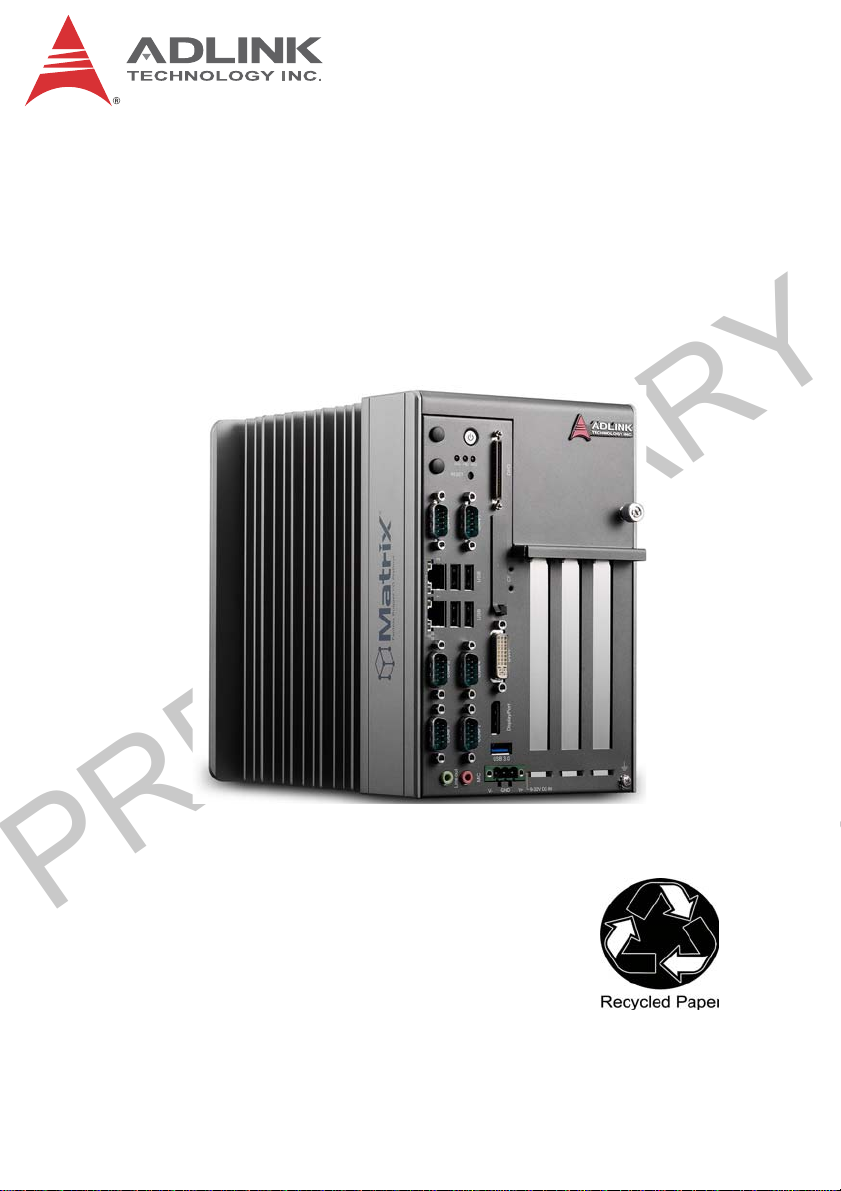
MXC-2300
Intel® Atom™ E3845 Quad-Core Processor-based
Fanless Expandable Embedded Computer
with PCI/PCIe Slots
Manual Rev.: PRELIMINARY
Revision Date: April 18, 2013
Part No: 50-PRE
Advance Technologies; Automate the World.
Page 2
PRELIMINARY
Revision History
Revision Release Date Description of Change(s)
PRELIMINARY April 18, 2013 Pre-Initial Release
Please note that this is a PRELIMINARY version of the
User’s Manual. While every effort has been made to
NOTE:
NOTE:
ensure the contents hereof are currently accurate, subsequent releases may contain changes to the specification and operations, both minor and major, as well as
entirely new chapters and modules not represented
here.
For more information or if you have any questions,
please visit our website at http//.www.adlinktech.com or
contact your local Sales Center, as detailed in Getting
Service.
ii
Page 3

PRELIMINARY
MXC-2300
Preface
Copyright 2014 ADLINK Technology, Inc.
This document contains proprietary information protected by copyright. All rights are reserved. No part of this manual may be reproduced by any mechanical, electronic, or other means in any form
without prior written permission of the manufacturer.
Disclaimer
The information in this document is subject to change without prior
notice in order to improve reliability, design, and function and does
not represent a commitment on the part of the manufacturer.
In no event will the manufacturer be liable for direct, indirect, special, incidental, or consequential damages arising out of the use or
inability to use the product or documentation, even if advised of
the possibility of such damages.
Environmental Responsibility
ADLINK is committed to fulfill its social responsibility to global
environmental preservation through compliance with the European Union's Restriction of Hazardous Substances (RoHS) directive and Waste Electrical and Electronic Equipment (WEEE)
directive. Environmental protection is a top priority for ADLINK.
We have enforced measures to ensure that our products, manufacturing processes, components, and raw materials have as little
impact on the environment as possible. When products are at their
end of life, our customers are encouraged to dispose of them in
accordance with the product disposal and/or recovery programs
prescribed by their nation or company.
Trademarks
Product names mentioned herein are used for identification purposes only and may be trademarks and/or registered trademarks
of their respective companies.
Preface iii
Page 4
PRELIMINARY
Conventions
Take note of the following conventions used throughout this
manual to make sure that users perform certain tasks and
instructions properly.
Additional information, aids, and tips that help users perform
tasks.
NOTE:
NOTE:
Information to prevent minor physical injury, component dam-
age, data loss, and/or program corruption when trying to com-
CAUTION:
WARNING:
plete a task.
Information to prevent serious physical injury, component
damage, data loss, and/or program corruption when trying to
complete a specific task.
iv Preface
Page 5

PRELIMINARY
MXC-2300
Table of Contents
Revision History...................................................................... ii
Preface.................................................................................... iii
List of Tables.......................................................................... ix
List of Figures........................................................................ xi
1 Introduction ........................................................................ 1
1.1 Overview.............................................................................. 1
1.2 Features............................................................................... 2
1.3 Specifications....................................................................... 3
1.4 Schematics and Dimensions ............................................... 7
1.5 Front Panel I/O Connectors ............................................... 11
1.5.1 Power Button ............................................................ 12
1.5.2 LED Indicators .......................................................... 13
1.5.3 Reset Button............................................................. 13
1.6 Digital I/O Connector ......................................................... 13
16-CH Isolated DI ......................................................... 13
16-CH Isolated DO ....................................................... 13
Isolated 5V DC Power Source for DO .......................... 14
General Specification .................................................... 14
1.6.1 Isolated Digital Input Circuits .................................... 16
1.6.2 Isolated Digital Output Circuits ................................. 19
1.6.3 Digital I/O Windows Driver and API.......................... 19
1.6.4 Controller Area Network (CAN) Port......................... 20
1.6.5 USB 2.0 Ports........................................................... 21
1.6.6 USB 3.0 Ports........................................................... 21
1.6.7 Gigabit Ethernet Ports .............................................. 21
1.6.8 Compact Flash Socket ............................................. 22
1.6.9 DVI-I Connector........................................................ 23
Table of Contents v
Page 6

PRELIMINARY
1.6.10 COM Port Connectors .............................................. 24
1.6.11 DisplayPort Connectors ............................................ 24
1.6.12 Audio Jacks .............................................................. 25
1.6.13 DC Power Connector................................................ 26
1.6.14 PCI Slot .................................................................... 27
1.6.15 PCI Express x4 Slot.................................................. 27
1.7 Internal I/O connectors....................................................... 28
1.7.1 Clear CMOS Jumper ................................................ 30
1.7.2 Internal Reserved +5V and +12V Connector............ 30
1.7.3 12V DC Fan Connector ............................................ 31
1.7.4 Internal USB Connector............................................ 31
1.7.5 SATA Connectors ..................................................... 31
1.7.6 Backboard to System PCB Connector...................... 32
2 Getting Started.................................................................. 33
2.1 Unpacking Checklist .......................................................... 33
2.2 Installing Hard Disk Drives................................................. 34
2.3 Installing a PCI/PCIe Card................................................. 39
2.4 Installing a mini-PCI-E device............................................ 41
2.5 Installing CF Cards ............................................................ 44
2.6 Connecting DC Power ....................................................... 47
2.7 Wall-mounting the MXC-2300............................................ 47
2.8 Optional Fan Module.......................................................... 51
2.9 Cooling Considerations...................................................... 52
3 Driver Installation.............................................................. 53
3.1 Installing the Chipset Driver............................................... 54
3.2 Installing the Graphics Driver............................................. 54
3.3 Installing the Ethernet Driver.............................................. 55
3.4 Installing the Audio Driver.................................................. 55
3.5 Installing the USB 3.0 Driver.............................................. 55
3.6 Installing the Intel Management Engine Driver.................. 56
vi Table of Contents
Page 7

PRELIMINARY
MXC-2300
3.7 Installing the WDT Driver/API............................................ 56
3.8 Installing the DI/O Driver/API............................................. 57
A Appendix: Power Supply & Consumption......................59
A.1 Power Consumption Reference ......................................... 59
A.2 Power Supply Reference ................................................... 60
A.3 Accessory Cabling ............................................................. 60
Important Safety Instructions.............................................. 61
Getting Service...................................................................... 63
Table of Contents vii
Page 8

PRELIMINARY
This page intentionally left blank.
viii Table of Contents
Page 9

PRELIMINARY
MXC-2300
List of Tables
Table 1-1: Front Panel I/O Connector Legend........................... 12
Table 1-2: LED Indicators .......................................................... 13
Table 1-3: Digital I/O Connector Pin Signals ............................. 15
Table 1-4: Digital I/O Connector Pin Legend ............................. 16
Table 1-5: CAN Port Pin Assignments....................................... 20
Table 1-6: Active/Link LED ........................................................ 22
Table 1-7: Speed LED ............................................................... 22
Table 1-8: DVI-I Connector Signals ........................................... 23
Table 1-9: D-Sub 9p Signal Function of Com Ports................... 24
Table 1-10: DisplayPort Pin Assignments ................................... 25
Table 1-11: Applicable Cable Types............................................ 25
Table 1-12: Audio Jack Signals ................................................... 26
Table 1-13: DC Power Supply Connector Signals....................... 27
Table 1-14: Mainboard Connector Legend .................................. 29
Table 1-15: Backplane Board Connector Legend........................ 29
Table 1-16: Clear CMOS Jumper Settings .................................. 30
Table 1-17: +5V and +12V Connector Pin Functions .................. 31
Table A-1: Power Consumption ................................................. 59
Table A-2: Power Supply ........................................................... 60
List of Tables ix
Page 10

PRELIMINARY
This page intentionally left blank.
xList of Tables
Page 11

PRELIMINARY
MXC-2300
List of Figures
Figure 1-1: MXC-2300 Functional Block Diagram ........................ 6
Figure 1-2: MXC-2300 Left Side View .......................................... 7
Figure 1-3: MXC-2300 Front View ................................................ 8
Figure 1-4: MXC-2300 Top View .................................................. 9
Figure 1-5: MXC-2300 Rear View ................................................. 9
Figure 1-6: MXC-2300 Underside View ...................................... 10
Figure 1-7: Front Panel I/O Connectors...................................... 11
Figure 1-8: Isolated Digital Input Circuit...................................... 17
Figure 1-9: Isolated Digital Input Differential Input Circuit........... 17
Figure 1-10: Isolated Digital Input Sample Application Circuit ...... 18
Figure 1-11: Isolated Digital Output Circuits ................................. 19
Figure 1-12: Isolated Digital Output Sample Application Circuit ... 19
Figure 1-13: CAN Port .................................................................. 20
Figure 1-14: DisplayPort Connector.............................................. 25
Figure 1-15: Mainboard PCB ........................................................ 28
Figure 1-16: Backplane Board PCB .............................................. 29
Figure 1-17: +5V and +12V Connector Pin Connector ................. 30
List of Figures xi
Page 12

PRELIMINARY
This page intentionally left blank.
xii List of Figures
Page 13

PRELIMINARY
1 Introduction
1.1 Overview
Featuring the latest Intel® Atom™ E3845 Quad-core processor,
the Matrix MXC-2300 series excels with minimal power consumption, exceptional 3D graphics, and powerful media acceleration,
delivering leading improvements in performance and cost-efficiency over any previous generation Atom-based system.
Including dual-port CAN connectivity supported by a Phillips
SJA1000 controller that can run independently or bridged at the
same time, bus arbitration and error detection with auto-correction
and re-transmission capability, and 16-CH isolated DI/O for general industrial control, the MXC-2300 features an increased total
3PCI/PCIe expansion slot count, supporting installation of a variety of off-the-shelf PCI/PCIe cards for configurable applications,
and an internal PCI Express Mini Card socket and USIM slot support extension of additional functions, such as wireless connection.
In addition, the MXC-2300series offers one DisplayPort and one
DVI-I port for dual independent display with full HD over HDMI,
four USB 2.0 and one USB 3.0 ports, and 2 GbE LAN ports with
teaming function.
MXC-2300
With ADLINK’s proprietary SEMA (Smart Embedded Management
Agent) tool, the MXC-2300 maximizes manageability and security
for a world of applications, providing efficient remote monitoring of
system activity and health in real time, system control over a
robust secured channel, and fully manageable complete utilization
of system resources.
With ruggedized architecture, flexibility, and rich I/O capacity, the
MXC-2300’s minimal power consumption, abundant features, and
leading performance and cost-efficiency make it the embedded
system of choice for industrial automation, facility management,
and intelligent transportation systems and applications demanding
reliability in harsh environments.
Introduction 1
Page 14

PRELIMINARY
1.2 Features
X Intel® Atom™ E3845 processor with 4C @1.91 GHz SoC
X 2x DDR3L SO-DIMM, supporting up to 8GB memory
X 2 PCI + 1 PCIe x4 or 3 PCI expansion slots
X Built-in dual-port isolated CAN and 16-CH isolated DI and
DO
X 1 DisplayPort + 1 DVI-I
X 2 Intel GbE ports with teaming function, 1 USB 3.0 + 4 USB
2.0 ports
X 1 external CF slot and 1 internal PCIe Mini Card socket with
USIM socket
X 2 software-programmable RS-232/422/485 + 2 RS-232
ports
X Built-in 9 to 32 VDC wide-range DC power input
X Rugged, -20°C to 70°C fanless operation (w/ industrial
SSD)
X Built-in ADLINK SEMA 1.0 (Smart Embedded Management
Agent))
This option guarantees cold boot of the system at -20°c
and operation with 100% loading at 60° without add-on
NOTE:
NOTE:
cards. The industrial solid-state drive storage option is
required.
2Introduction
Page 15
PRELIMINARY
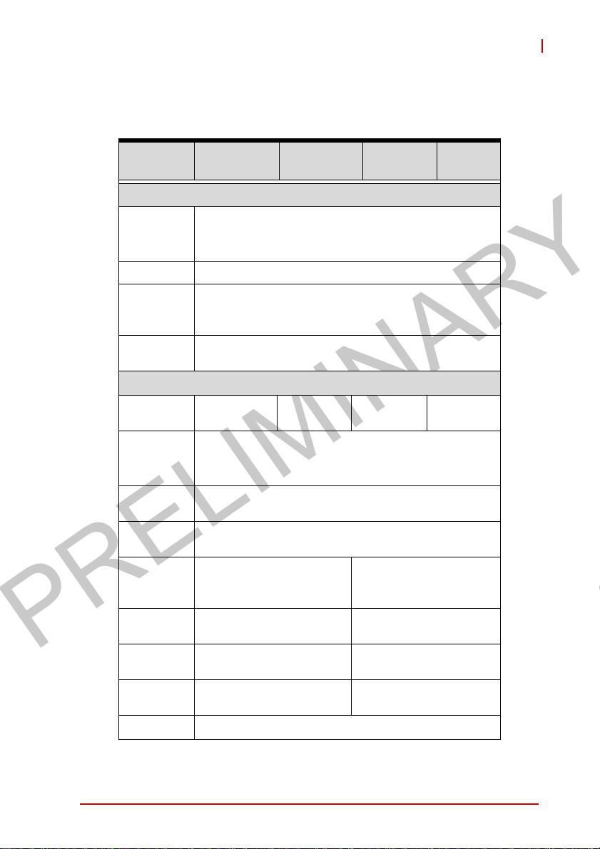
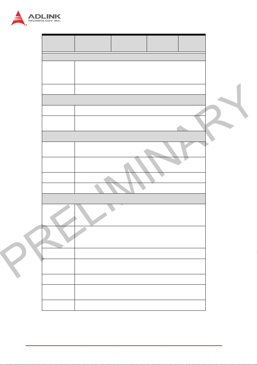
1.3 Specifications
MXC-2300
MXC-
2300CD-3E1
System Core
Processor
Chipset Intel SoC (System on Chip)
Video
Memory
I/O Interface
Expansion
slots
Ethernet
Serial Ports
USB
CAN
DIO
Mini PCIe
USIM
Audio 1 MIC-in and 1 Line-out
Intel® Atom™ Processor E3845 (Bay Trail-I
1 DisplayPort +1 DVI-I (VGA or DVI-D)
DP: resolution up to 2560x1600
VGA: resolution up to 1600x1200
4GB DDR3L 1333MHz SODIMM module, (up to
2 PCI+1
PCIe x4
®
2 Intel
GbE ports (Intel® Springville WGI210IT
Teaming function, Wake On LAN
2 software-programmable RS-232/422/485 (COM
1&2) with auto-flow control, 2 RS-232 (COM 3&4)
5 external USB ports (4 USB 2.0 + 1 USB 3.0) + 1
2 DB9 isolated CAN port
with SjA1000 CAN
controller
16-CH DI and 16-CH DO
with 1.5KV isolation
1 internal mini PCIe card
socket
1 USIM socket for 3G
communication
MXC-
2300CD-3S
Premium)
4C @ 1.91GHz CPU
8GB with 2 SODIMM sockets)
3 PCI
chipset)
internal USB 2 .0
MXC-
2300-3E1
2 PCI+1
PCIe x4
MXC-
2300-3S
3 PCI
-
-
-
-
Introduction 3
Page 16
PRELIMINARY
MXC-
2300CD-3E1
Power Supply
Built-in 9-32 V
DC Input
AC Input Optional 100 W external AC-DC adapter for AC input
Storage
SATA HDD Onboard SATA-II port for 2.5” HDD/SSD installation
CompactFl
ash
Mechanical
Optional
Fan Module
Dimensions
Weight 3.5 kg
Mounting Wall-mount kit
Environmental
Operating
Temperatur
e
Storage
Temperature-40°C to 85°C (-40˚F to 185˚F) (excl. HDD/SDD/CF)
connectors with latch (GND, V-, V+), 2-pin remote
Optional fan module for heat dissipation, smart fan
142 (W) x219 (D) x210(H) mm (WxDxH) (5.84” x
Standard: 0°C to 50°C (32˚F to 122˚F)
Extended Temperature: -20°C to 70°C (-4˚F to
158˚F) (w/industrial SSD or CF)
MXC-
2300CD-3S
wide-range DC input pluggable
DC
power on/off switch
1 CompactFlash socket
control
8.76” x 8.4)
MXC-
2300-3E1
MXC-
2300-3S
Humidity ~95% @ 40°C (104˚F) (non-condensing)
Vibration
ESD Contact +/-4 KV and Air +/-8 KV
Shock
EMC CE and FCC Class A, UL/cUL
4Introduction
Operating, 5 Grms, 5-500 Hz, 3 axes (w/ CF or SSD)
Operating, 0.5 Grms, 5-500 Hz, 3 axes (w/ HDD)
Operating, 50 G, half sine 11 ms duration (w/ CF or
SSD)
Page 17
PRELIMINARY
NOTE:
NOTE:
MXC-2300
Extending operating temperature to the -20°C to +60°C range
is optional and requires an industrial solid-state storage drive.
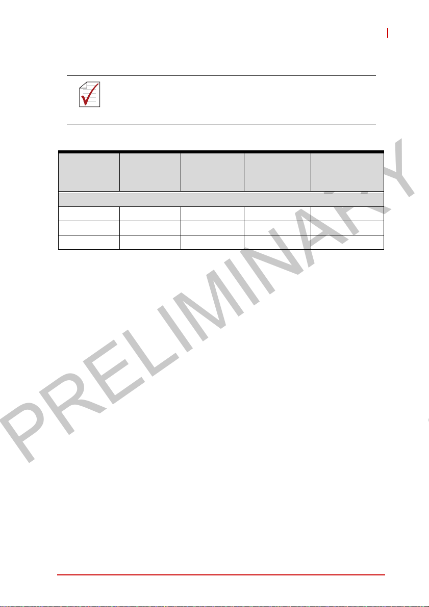
Power
Supply
(24VDC)
MXC-2300 i7 2.16 W 18.48 W 91.2 W 160W
MXC-2300 i5 2.16 W 16.8 W 67.2 W 160W
MXC-2300 i3 2.16 W 16.08 W 53.76 W 160W
*In shutdown status with DC input and only PS2 keyboard/mouse
connected
Power Off*
Integrated Embedded Computer
System
Idle**
System Full
Load***
Recommended
Power
Supply****
**Under Windows 7 desktop with no application programs exe-
cuted
***Under Windows 7 with 100% CPU utilization and simultaneous
access to all I/O devices
****Additional power supply is necessary if add-on cards are
installed and in use
Introduction 5
Page 18
PRELIMINARY
16ch
D I/O
IO Board
CAN Bus
Connector
x2
RJ45 &
USB2.0 x 2
Connector
RJ45 &
USB2.0 x 2
Connector
Line out &
Mic in
Connector
Dsub -9
x4
DisplayPort
connector
DVI-I
Connector
DVI
CAN Bus
GbE I/F
USB 2.0
GbE I/F
USB 2.0
DVI
level shifter
FPGA
GbE controller
Intel WGI210IT
GbE controller
Intel WGI210IT
DDI0
CRT
DDI1
PCIe x1
PCIe x1
PCIe x1
Audio
COM x4
Intel࿗ Atom
E3845 1.91GHz
Processor
LPC
Super I/O
ITE IT8786F
DDR3L
1333MHz
DDR3L
1333MHz
SATA II
PCIe x2
PCIe x1
USB 2.0
SATA II
204 pin SODIMM
204 pin SODIMM
PCIE x1
SMBus
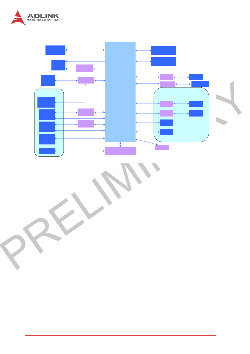
Figure 1-1: MXC-2300 Functional Block Diagram
Channel A
Channel B
Switch
MiniPCIe v1.2
Switch
PCIe to PCI bridge
Internal
SATA
Connector
SEMA BMC
PCIe
PCIe
USB
IDE
PCIe x4
PCI
CF Slot
USIM Socket
Riser Card
PCIe x4
slot
PCI slot
X2
6Introduction
Page 19
PRELIMINARY
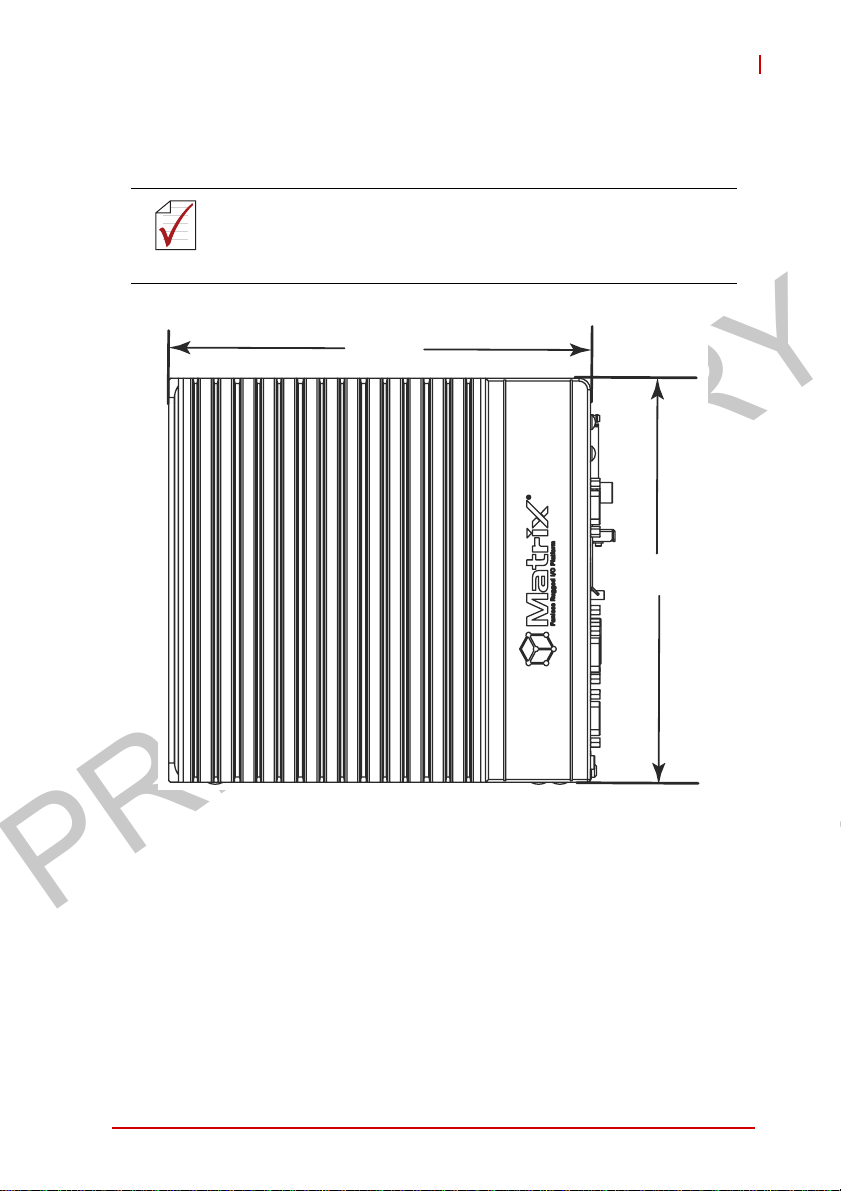
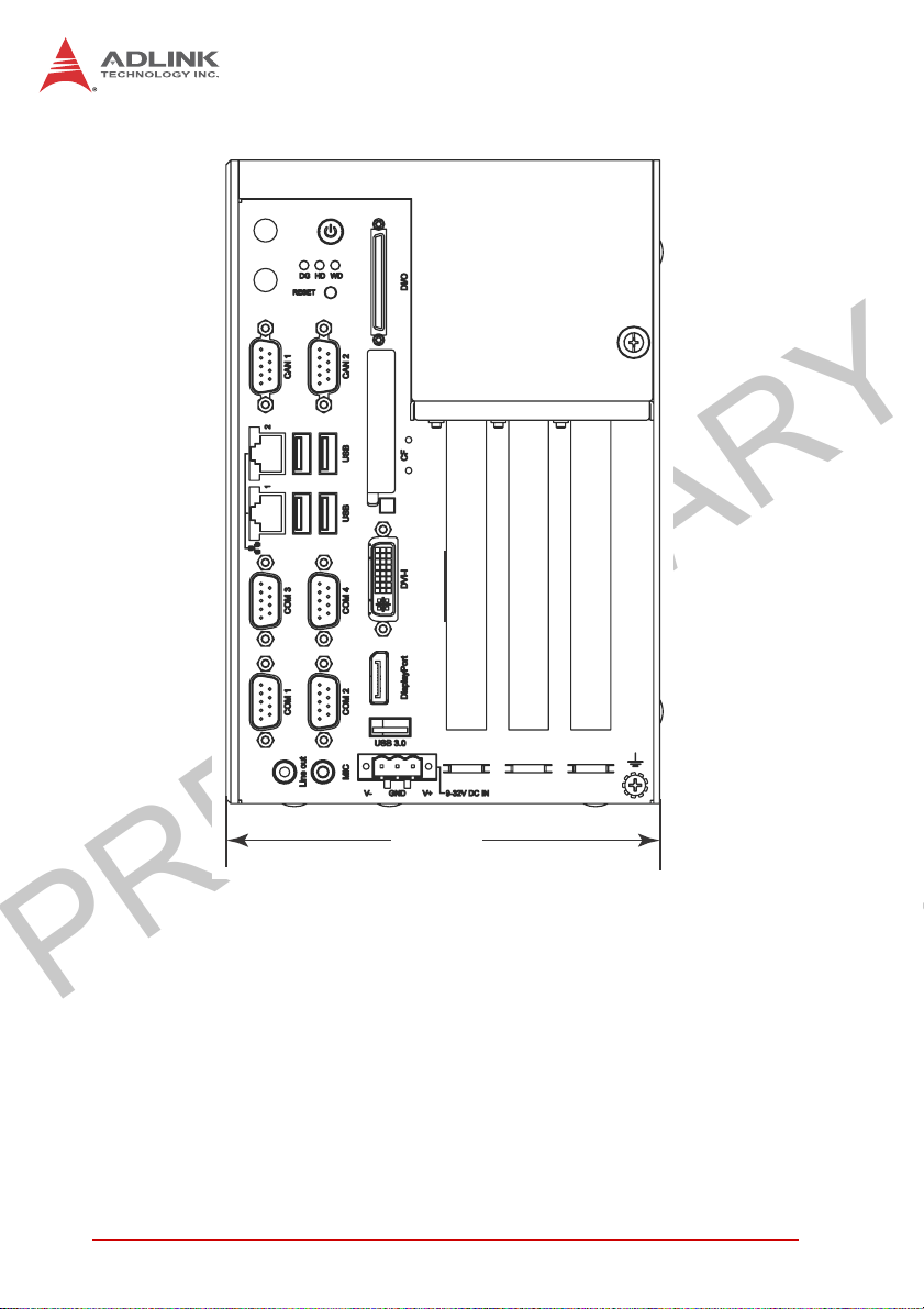
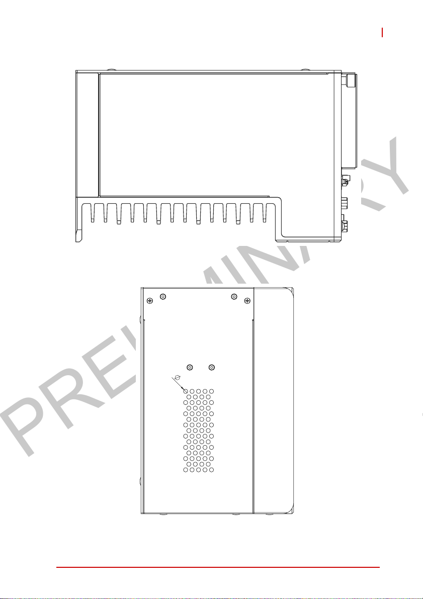
1.4 Schematics and Dimensions
All dimensions shown are in mm (millimeters).
NOTE:
NOTE:
219.1
MXC-2300
210
Figure 1-2: MXC-2300 Left Side View
Introduction 7
Page 20
PRELIMINARY
141.6
Figure 1-3: MXC-2300 Front View
8Introduction
Page 21
PRELIMINARY
Figure 1-4: MXC-2300 Top View
MXC-2300
4
Figure 1-5: MXC-2300 Rear View
Introduction 9
Page 22
PRELIMINARY
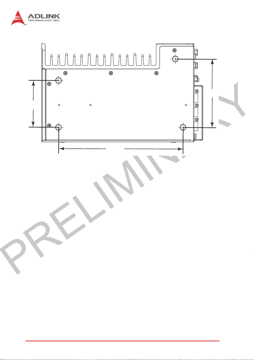
67.3
98.3
179.1
Figure 1-6: MXC-2300 Underside View
10 Introduction
Page 23
PRELIMINARY
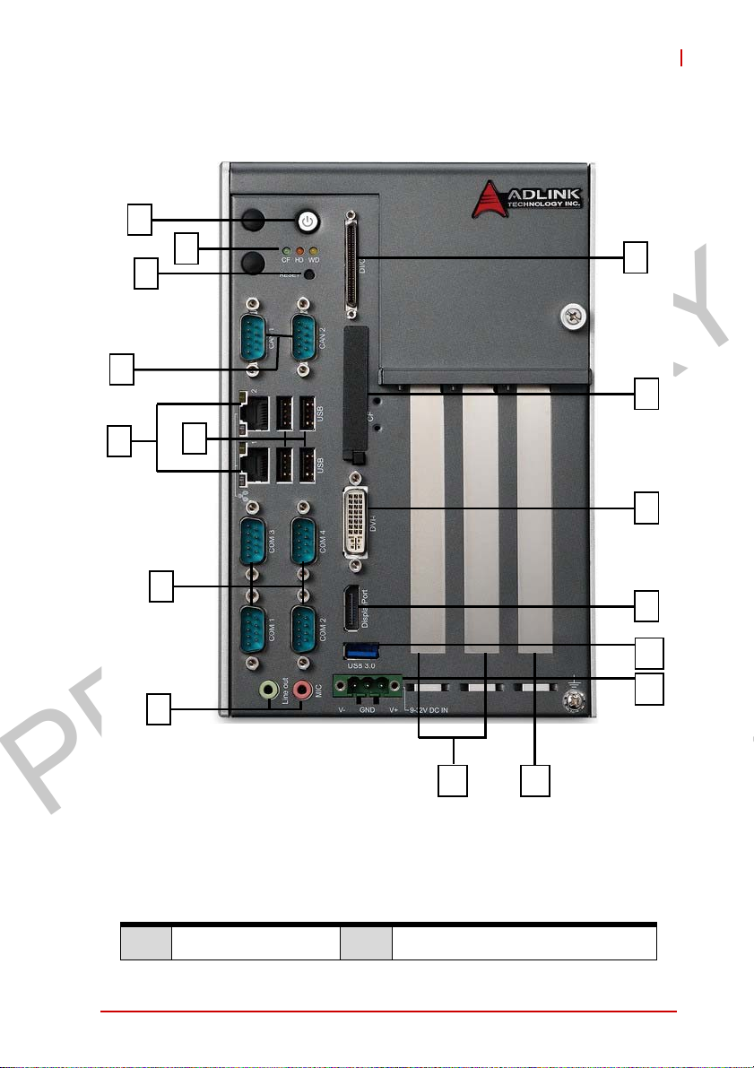
1.5 Front Panel I/O Connectors
A
B
C
D
MXC-2300
I
J
E
A Power Button I Digital I/O connector
F
G
H
O
Figure 1-7: Front Panel I/O Connectors
K
L
M
N
P
Introduction 11
Page 24

PRELIMINARY
B LED Indicators J Compact-Flash slot
C Reset Button K DVI-I connector
D DB9 CAN Bus x2 L DisplayPort connector
E GbE x2 M USB3.0 connector
F USB2.0 connector x4 N DC power supply connector
G COM port x4 O 5V 32-Bit PCI slot x 2
H Audio Jacks P
Table 1-1: Front Panel I/O Connector Legend
1.5.1 Power Button
The power button is a non-latched push button with a blue LED
indicator. System is turned on when the button is depressed, and
the power LED lights. If the system hangs, depress the button for
5 seconds to turn off the system completely.
PCIExpressx4slot(MXC-2300-3E1)
5V 32-Bit PCI slot (MXC-2300-3S)
12 Introduction
Page 25

PRELIMINARY
MXC-2300
1.5.2 LED Indicators
In addition to the LED of the power button, three LEDs on the front
panel indicate the following.
LED indicator Color Description
Indicates watchdog timer status. When
Watchdog (WD) Yellow
Hard disk drive
(HD)
Diagnostic (DG) Green
Orange
T able 1-2: LED Indicators
watchdog timer starts, the LED flashes.
When the timer is expired, the LED
remains lit..
Indicates the HDD operating state.
When the SATA hard drive or CFast card
is active, the LED indicator flashes.
When lit continuously, indicates no
physical storage is connected, and if
blinking, indicates no memory is
installed on either SODIMM socket.
1.5.3 Reset Button
The reset button executes a hard reset for the MXC-2300.
1.6 Digital I/O Connector
The MXC-2300 controller features an onboard isolated digital I/O
circuit with a 68-pin VHDCI (Very High Density Cable Interconnect) connector on the front panel. The onboard digital I/O card
supports the following features:
16-CH Isolated DI
X Logic high: 5 to 24 V
X Logic low: 0 to 1.5 V
X Input resistance: 8.2K @ 0.75W
X Isolation type: photocoupler
X Isolation voltage: 1500 V DC
16-CH Isolated DO
X Output Type: MOSFET transistor
Introduction 13
Page 26

PRELIMINARY
X Sink current up to 100 mA (sustained loading) or 250 mA
(peak loading) on each isolated output channel
X Supply voltage: 5 to 35 V DC
X Isolation type: Digital Isolator
X Isolation voltage: 1500 V DC
X Flywheel diode for VDD on all DO channels
Isolated 5V DC Power Source for DO
X Supply voltage: 5 ± 0.5V DC
X Supply current: 180 mA (maximum)
X Isolation type: DC-to-DC transformer
X Isolation voltage: 1500 VRMS (channel to system)
General Specification
X 68-pin VHDCI (Very High Density Cable Interconnect) con-
nector (mating with AMP 787082-7) on the front panel
X Optional accessories: DIN-68S-01 and ACL-10568-1
X Data transfer: programmed IO
X Software Driver support: please download from our website
14 Introduction
Page 27

PRELIMINARY
MXC-2300
Pin Signal Pin Signal Pin Signal
1 +VDD 24 DI1_L 47 EOGND
2 EOGND 25 DI0_H 48 DO10
3 DO7 26 DI0_L 49 EOGND
4 EOGND 27 DI11 50 DO9
5 DO6 28 ISO_COM 51 EOGND
6 EOGND 29 DI10 52 DO8
7 DO5 30 ISO_COM 53 DI7_H
8 EOGND 31 DI9 54 DI7_L
9 DO4 32 ISO_COM 55 DI6_H
10 EOGND 33 DI8 56 DI6_L
11 DO3 34 ISO_COM 57 DI5_H
12 EOGND 35 +VDD 58 DI5_L
13 DO2 36 +V5DIO_CN_ISO 59 DI4_H
14 EOGND 37 EOGND 60 DI4_L
15 DO1 38 DO15 61 DI15
16 EOGND 39 EOGND 62 ISO_COM
17 DO0 40 DO14 63 DI14
18 EOGND 41 EOGND 64 ISO_COM
19 DI3_H 42 DO13 65 DI13
20 DI3_L 43 EOGND 66 ISO_COM
21 DI2_H 44 DO12 67 DI12
22 DI2_L 45 EOGND 68 ISO_COM
23 DI1_H 46 DO11
T able 1-3: Digital I/O Connector Pin Signals
Introduction 15
Page 28

PRELIMINARY
DIn_H
DIn_L
DI
DIn
ISO_COM
DOn
EOGND
DO
+VDD
+V5DIO_CN_ISO Isolated 5V DC power, maximum output 180mA
Table 1-4: Digital I/O Connector Pin Legend
1.6.1 Isolated Digital Input Circuits
Input accepts voltages up to 24V, with input resistors of 8.2 kΩ,
with connections between outside signals as shown.
High input of isolated differential DI channel
(n=0 to 7)
Low input of isolated differential DI channel
(n=0 to 7)
Input of isolated DI channel
(n=8 to 15)
Common ground of isolated DI channel
8 to 15
Output of isolated DO channel
(n=0 to 15)
Ground return path of isolated DO channel
0 to 15 and +V5DIO_CN_ISO
Power input signal for flywheel diode of isolated
DO channel
0 to 15
Photocoupler
DIn
ISO_COM
16 Introduction
8.2K Ohm
DI_n
GND
Page 29

PRELIMINARY
Figure 1-8: Isolated Digital Input Circuit
Photocoupler
MXC-2300
DIn
ISO_COM
Figure 1-9: Isolated Digital Input Differential Input Circuit
8.2k
DI_n
GND
Introduction 17
Page 30

PRELIMINARY
Power
Photocoupler
8.2 k
DIn
ISO_COM
Power
DIn
ISO_COM
DI_n
GND
Photocoupler
8.2 k
DI_n
GND
Figure 1-10: Isolated Digital Input Sample Application Circuit
18 Introduction
Page 31

PRELIMINARY
MXC-2300
1.6.2 Isolated Digital Output Circuits
Each isolation digital output channel adopts a MOSFET transistor,
capable of driving peak current up to 250mA (sustained current up
to 100 mA) with voltage ranges from 5V to 35V.
The VDD pin is connected in serial with a flywheel diode protecting
the driver during inductance loading, such as relay, motor, or solenoid, wherein the VDD must connect to external power to form a
flywheel current loop.
+VDD
Flywheel
Diode
DOn
EOGND
Figure 1-11: Isolated Digital Output Circuits
+VDD
DC
(5~35V)
Load
Figure 1-12: Isolated Digital Output Sample Application Circuit
DOn
EOGND
Flywheel
Diode
MOSFET
+V5DIO_ISO
+V5DIO_ISO
MOSFET
Photocoupler
Photocoupler
1.6.3 Digital I/O Windows Driver and API
The MXC-2300 DI/O incorporates ADLINK’s PCMe-1432 Windows driver, on the bundled driver CD or downloadable from
Adlink's MXC-2300 web support page (driver for MXC-2300 DI/O).
DO_BUF_n
GND
DO_BUF_n
GND
Introduction 19
Page 32

PRELIMINARY
1.6.4 Contr oller Area Network (CAN) Port
1 5
6
Figure 1-13: CAN Port
Pin Signal Pin Signal
1N/A6N/A
2 CAN_L 7 CAN_H
3GND8N/A
4N/A9N/A
5N/A
T able 1-5: CAN Port Pin Assignments
The Controller Area Network (CAN) interface supports dual-port
isolated CAN connection that can run independently or bridged at
the same time. The built-in CAN controller is a Phillips SJA1000,
providing bus arbitration and error detection with auto correction
and re-transmission capability, and features:
X Dual independent CAN network operation
X Bridge function support
X Compatibility with CAN specification 2.0 parts A and B
X Optically isolated CAN interface with up to 1000 Vrms isola-
tion protection
X Direct memory mapping to CAN controllers
X Powerful master interface for CANopen, DeviceNet and
SDS application layer protocol
9
20 Introduction
Page 33

PRELIMINARY
MXC-2300
X Up to 1Mbps programmable transfer
X Support for standard DeviceNet data rates 125, 250 and
500 Kbps
1.6.5 USB 2.0 Ports
The MXC-2300 provides four USB 2.0 ports supporting Type A
USB connection on the front panel. All USB ports are compatible
with high-speed, full-speed and low-speed USB devices. The
MXC-2300 supports multiple boot devices, including USB flash
drive, USB external hard drive, USB floppy, USB CD-ROM and
others. The boot priority and boot device can be configured in
BIOS. Please refer to Section B.8: Security on page 88 for details.
1.6.6 USB 3.0 Ports
The MXC-2300 provides a USB 3.0 port supporting Type A USB
3.0 connection on the front panel, compatible with super-speed,
high-speed, full-speed and low-speed USB devices.
1.6.7 Gigabit Ethernet Ports
The MXC-2300 has two Gigabit Ethernet ports on the front panel,
supporting the Intel WGI210IT GbE controller, which provides:
X IEEE 802.3az Energy Efficient Ethernet
X IEEE 1588/802.1AS precision time synchronization
X IEEE 802.3Qav traffic shaper
X Interrupt moderation, VLAN support, IP checksum offload
X PCIe OBFF (Optimized Buffer Flush/Fill) for improved sys-
tem power management
X Four transmit and four receive queues
X RSS and MSI-X to lower CPU utilization in multi-core sys-
tems
X ECC - error correcting memory in packet buffers
X Wake-On-LAN
X NC-SI for increased bandwidth passthrough
X Preboot eXecution Environment (PXE) flash interface
X Jumbo frame support
Introduction 21
Page 34

PRELIMINARY
X LAN Teaming
Active/Link
Yell ow
LED Color Status Description
OFF Ethernet port is disconnected.
Yell ow
1.6.8 Compact Flash Socket
A Type I Compact-Flash socket provides +3.3V voltage to a CF
card. The CF interface is transferred from SATA by an ASIC, and
can be an alternative storage device for system installation. The
MXC-2300 can boot via a CF card with OS installed. Due to the
nature of the SATA interface, the CF card cannot hot-plug and
must be installed before powering up the system.
ON Ethernet port is connected with no activity.
Flashing Ethernet port is connected and active.
Table 1-6: Active/Link LED
LED Color Status Description
OFF 10 Mbps
Green/Orange
Green 100 Mbps
Orange 1000 Mbps
T able 1-7: Speed LED
Speed LED
Green/Orange
22 Introduction
Page 35

PRELIMINARY
MXC-2300
1.6.9 DVI-I Connector
The MXC-2300 provides one DVI-I connector providing connection to an external monitor.
Since VGA signals are analog based, VGA display quality is
greatly affected by quality and length of cable used. We
CAUTION:
Pin Signal Pin Signal Pin Signal Pin Signal
1 DVIdata 2- 9 DVIdata 1- 17 DVIdata 0- C1
2 DVIdata 2+ 10 DVIdata 1+ 18 DVIdata 0+ C2
3 GND 11 GND 19 GND C3
4 CRT DDC clock 12 N/C 20 N/C C4
5 CRT DDC data 13 N/C 21 N/C C5
6 DVIDC clock 14 +5V 22 GND
7 DVIDC data 15 GND 23 DVI clock +
8
strongly recommended VGA cable less than 2 meters in length
with effective shielding, such as UL style 2919 AWM.
Analog vert.
sync
16
Hot plug
detect
24 DVI clock -
Analog
Red
Analog
Green
Analog
Blue
Analog
horiz.
sync
Analog
GND
Table 1-8: DVI-I Connector Signals
Introduction 23
Page 36

PRELIMINARY
1.6.10 COM Port Connectors
The MXC-2300 provides four COM ports through D-sub 9 pin connectors. The COM1 & COM2 ports support RS-232/422/485
modes by BIOS setting, while COM3 and COM4 support only RS-
232.
Pin
Table 1-9: D-Sub 9p Signal Function of Com Ports
1.6.11 DisplayPort Connectors
Two displayport connectors on the front panel can connect to
VGA, DVI, HDMI and DisplayPort monitors via DisplayPort to VGA
adapter cable, DisplayPort to DVI adapter cable, or DisplayPort to
HDMI adapter cable and DisplayPort cable.
Signal Name
RS-232 RS-422 RS-485
1 DCD# TXD422- 485DATA-
2 RXD TXD422+ 485DATA+
3 TXD RXD422+ N/S
4 DTR# RXD422- N/S
5 GND N/S N/S
6DSR# N/S N/S
7RTS# N/S N/S
8CTS# N/S N/S
9RI# N/S N/S
19
1
20
24 Introduction
2
Page 37

PRELIMINARY
Figure 1-14: DisplayPort Connector
Pin Signal Pin Signal
1 CN_DDPx0+ 11 GND
2 GND 12 CN_DDPx3-
3 CN_DDPx0- 13 CN_DDPx_AUX_SEL
4 CN_DDPx1+ 14 CN_DDPx_CONFIG2
5 GND 15 CN_DDPx_AUX+
6 CN_DDPx1- 16 GND
7 CN_DDPx2+ 17 CN_DDPx_AUX-
8 GND 18 CN_DDPx_HPD
9 CN_DDPx2- 19 GND
10 CN_DDPx3+ 20 +V3.3_DDPx_PWR_CN
Table 1-10: DisplayPort Pin Assignments
P/N Description
30-01119-0000 Passive DisplayPort to HDMI adapter cable
30-01120-0000 Passive DisplayPort to DVI adapter cable
30-01121-0000 Passive DisplayPort to VGA adapter cable
30-01157-0000 Active DisplayPort to DVI adapter cable
MXC-2300
Table 1-11: Applicable Cable Types
1.6.12 Audio Jacks
The MXC-2300 implements Intel High Definition audio on a
Realtek ALC269 chip. The HD audio supports up to 24-bit, 192
KHz sample rate high quality headphone/line out and microphone
Introduction 25
Page 38

PRELIMINARY
input. Audio jack access is on the front panel. The pink jack provides microphone input, and the green jack line out.
Color Signal
Green lineout
Pink Mic In
T able 1-12: Audio Jack Signals
1.6.13 DC Power Connector
The DC power supply connector of the MXC-2300 is on the front
panel. The power supply connector consists of three pins, V+,
chassis ground, and V- from right to left respectively. V+ and Vpins provide DC power input and the chassis ground pin allows
connection of the chassis to ground for better EMC compatibility.
The DC power input for the MXC-2300 allows a voltage input
range from 9 V DC to 32 V DC.
Ensure that the DC power supply:
X is within the input voltage range defined in the
WARNING:
DC power supply over or under voltage, unstable, or of insufficient power may cause system instability and physical damage
26 Introduction
specification
X is stable and low-noise DC
X provides sufficient operating current
Page 39

PRELIMINARY
MXC-2300
Pin Signal
1V+ (DC_IN)
2 GND (CHGND)
3 V- (DGND)
Table 1-13: DC Power Supply Connector Signals
1.6.14 PCI Slot
The MXC-2300 provides two PCI slots, based on the PCIe to PCI
bridge, with connection to the host system achieved through a
PCIe interface, supporting universal or 5V PCI 32-bit cards operating at 33/66MHz clocks.
1.6.15 PCI Express x4 Slot
The PCI Express x4 slot on the backplane board, based on the
PCI Express switch, connects to the host system through a PCI
Express x2 Gen2 interface. The PCI Express slot can support
standard PCI Express x4 Gen1 cards.
Introduction 27
Page 40

PRELIMINARY
1.7 Internal I/O connectors
EF
D
G
ABC
H
Figure 1-15: Mainboard PCB
A Clear CMOS jumper
B CMOS RTC Battery
C Reserved +5V and +12V connector
D Extra +5V voltage connector
E Extra +3.3V voltage connector
28 Introduction
Page 41

PRELIMINARY
MXC-2300
F 12V DC fan connector
G Mini PCI Express slot & USIM socket
H 2nd DDR3L DIMM socket
T able 1-14: Mainboard Connector Legend
D
A
E
F
Figure 1-16: Backplane Board PCB
A 5V 32Bit PCI slot
B 5V 32Bit PCI slot
C PCI Express x4 slot
D Internal USB dongle connector
E SATA connector
F Connector to mainboard PCB
Table 1-15: Backplane Board Connector Legend
B
C
Introduction 29
Page 42

PRELIMINARY
1.7.1 Clear CMOS Jumper
Upon encountering an abnormal condition preventing the MXC2300 from booting, the jumper can clear the BIOS content stored
in CMOS and restore default settings. To clear CMOS, short pin
#1 to pin #2 of JP1 and then remove the jumper to return to normal
mode.
Normal Clear
JP1/JP2
Table 1-16: Clear CMOS Jumper Settings
1.7.2 Internal Reserved +5V and +12V Connector
The MXC-2300 provides one power pin header with +5V and
+12V DC power, providing access for PCI and PCI express card
external power supplies.
Please refer to Section A.2:Power Supply Reference for +5V and
+12V connector power supply specifications
JP1/JP2
CN17
1
Figure 1-17: +5V and +12V Connector Pin Connector
30 Introduction
Page 43

PRELIMINARY
MXC-2300
Pin Signal
1 +12V
2GND
3GND
4+5V
Table 1-17: +5V and +12V Connector Pin Functions
1.7.3 12V DC Fan Connector
The MXC-2300 provides a DC 12V to USB connector for fan module power. The optional fan module connects to the connector
when assembled to the chassis.
Fan speed changes with CPU temperature according to thermal
sensor, initiating at 40°C(104°F), and reaching maximum speed at
80°C (176°F). The fan rotates at maximum speed when Power On
Self Test begins.
The USB connector does not support standard USB connections, which may be damaged by the DC 12V power supply.
WARNING:
1.7.4 Internal USB Connector
The MXC-2300 provides an internal USB dongle connector on the
backboard.
1.7.5 SATA Connectors
The MXC-2300 provides one SATA port, supporting up to 3.0 Gb/s
(300MB/s) transfer rate. The SATA host controller can be set to
operate in IDE or AHCI mode in BIOS.This SATA connector is
designed to support a 2.5 inch hard disk drive (HDD) or solid state
disk (SSD). The HDD or SSD must be installed into the SATA connector with a HDD bracket. Please refer to Section 3.1 for installation of a 2.5 inch HDD or SSD.
Introduction 31
Page 44

PRELIMINARY
1.7.6 Backboard to System PCB Connector
This connector connects the backboard to a golden fingerequipped mainboard PCB.
32 Introduction
Page 45

PRELIMINARY
2 Getting Started
This chapter discusses installation of a hard disk drive, a PCI/PCIe
card and a CF card in the system. In addition to connection and
use of mini-PCI-E device, wall-mounting is also described.
2.1 Unpacking Checklist
Before unpacking, check the shipping carton for any damage. If
the shipping carton and/or contents are damaged, inform your
dealer immediately. Retain the shipping carton and packing
materials for inspection. Obtain authorization from your dealer
before returning any product to ADLINK. Ensure that the following items are included in the package.
X MXC-2300 controller
X Accessory box
X Screw pack for wall-mounting and HDD fixing
X Quick Start Guide
X ADLINK All-in-One DVD
MXC-2300
Getting Started 33
Page 46

PRELIMINARY
2.2 Installing Hard Disk Drives
Before installing hard disk drives, remove the cover from the chassis as follows.
1. Loosen the thumbscrew on the front panel by hand or
screwdriver.
34 Getting Started
Page 47

PRELIMINARY
MXC-2300
2. Withdraw the thumbscrew and remove the top cover by
lifting.
Getting Started 35
Page 48

PRELIMINARY
3. Remove 2 screws from the back cover.
4. Place the chassis upside down and remove the other 2
screws from the bottom of the back cover.
36 Getting Started
Page 49

PRELIMINARY
5. Lift and pull the back cover.
MXC-2300
Getting Started 37
Page 50

PRELIMINARY
6. Use the 4 M3 screws included in the package to fix a
2.5” HDD or SSD unit to the bracket.
7. Gently reinstall the cover and depress the HDD/SSD
bracket to the SATA connector on the PCB.
8. Reverse Steps 3 and 4 to fasten the 4 screws.
9. Replace the top cover and fasten the thumbscrew.
38 Getting Started
Page 51

PRELIMINARY
MXC-2300
2.3 Installing a PCI/PCIe Card
Follow steps 1-2 in Section 2.2:Installing Hard Disk Drives to
remove the top cover before installing a PCI/PCIe card.
1. Insert thePCI/PCIe card into the PCI/PCIe slot. Ensure
that the lower edge of the PCI/PCIe card aligns with the
alignment guide.
Getting Started 39
Page 52

PRELIMINARY
2. Adjust the position of the included card brace to firmly fix
the card.
Tighten the screw to fix the brace.
3. Replace the top cover and fasten the thumbscrew.
40 Getting Started
Page 53

PRELIMINARY
2.4 Installing a mini-PCI-E device
According to steps 1-2 in Section 2.2, remove the top cover.
1. Remove 4 screws from the right side cover.
MXC-2300
2. Remove the single screw from the back cover.
Getting Started 41
Page 54

PRELIMINARY
3. Place the chassis left side down and lift the left side
cover.
4. Insert the mini-PCI-E wireless module into the slot at an
angle.
42 Getting Started
Page 55

PRELIMINARY
5. Press the mini-PCI-E wireless module until seated and
fix with the 2 M2.5-P-head-L5 screws.
6. Reverse Steps 1 to 3 to reinstall the left side cover and
fasten the 5 screws, then replace the top cover and fasten the thumbscrew.
MXC-2300
Getting Started 43
Page 56

PRELIMINARY
2.5 Installing CF Cards
The MXC-2300 series controller provides an external CF socket to
accommodate a CF card. Remove the top cover according to
steps 1-2 in Section 2.2.
1. Remove the external CF socket cover.
44 Getting Started
Page 57

PRELIMINARY
2. Align the CFast card with the guide of the CFast socket.
MXC-2300
Getting Started 45
Page 58

PRELIMINARY
3. Gently insert the CFast card until it is firmly seated in the
socket, as shown.
46 Getting Started
Page 59

PRELIMINARY
MXC-2300
2.6 Connecting DC Power
Before connecting DC power to the MXC-2300, ensure voltage
and polarity are compliant with the DC input. Improper input
WARNING:
The DC power input connector of the MXC-2300 has V+, V- , and
chassis ground pins, and accepts input voltage as shown previously. Connect DC power as shown. Two screws fasten to secure
the plug.
voltage or polarity can cause system damage.
2.7 Wall-mounting the MXC-2300
All dimensions shown are in mm (millimeters).
NOTE:
NOTE:
The MXC-2300 is shipped with wall-mount brackets and accessory screws.
Getting Started 47
Page 60

PRELIMINARY
Wall–mounting procedures follow.
1. Remove the 4 plastic pads from the corners.
2. Use the 4 M4 screws shipped with the controller to fix
the 2 wall-mount brackets, also included, to the chassis,
according to the spacing dimensions of the screw holes
and brackets, as shown.
48 Getting Started
Page 61

PRELIMINARY
MXC-2300
84
182
84
229.1
243.1
Getting Started 49
108
168
Page 62

PRELIMINARY
7.2
5.2
5.2
3. Once final assembly as shown is complete, mount the
MXC-2300 on the wall via screw holes.
10.0
25.2
50 Getting Started
Page 63

PRELIMINARY
MXC-2300
2.8 Optional Fan Module
The MXC-2300 can be optionally equipped with an easily installed
fan module providing heat dissipation.
To install the fan module:
1. Follow steps 1-2 in Section 2.2 to remove the top cover.
Seat the fan module in the chassis.
Getting Started 51
Page 64

PRELIMINARY
2. Slide the fan module back until USB connection is
secured, as shown.
3. Replace the thumbscrews.
2.9 Cooling Considerations
Heat-generating components of the MXC-2300 (such as CPU and
PCH) are all situated on the left side of the system. These components directly contact the heat sink via thermal pads and dissipate
heat generated by the components. To maximize efficiency of heat
dissipation, maintain a minimum of 2 inches (5 cm) clearance on
the top of the MXC-2300 controller.
52 Getting Started
Page 65

PRELIMINARY
3 Driver Installation
After installing the operating system, all related drivers must be
installed for the system to function properly. This section describes
the drivers needed for Windows operating systems and the
procedures to install them. For other OS support, please contact
ADLINK for further information.
The MXC-2300 enables full driver support for systems running
Windows 8 32 or 64 bit.
Ensure the Microsoft Windows OS is fully installed before
installing any drivers, since most standard I/O device drivers
NOTE:
NOTE:
It is recommended that drivers be installed as follows.
are included therein
1. Chipset driver
2. Graphics driver
3. Ethernet driver
4. Audio driver
MXC-6300
5. USB 3.0 driver
6. Intel Management Engine driver
7. WDT (watchdog timer) driver
8. Digital Input/Output driver
Driver Installation 53
Page 66

PRELIMINARY
3.1 Installing the Chipset Driver
The chipset driver directs the operating system to configure the
®
NM10chipset components in order to ensure that the follow-
Intel
ing features function properly:
X SATA Storage Support
X USB Support
X Identification of Intel
Manager
1. Close any running applications.
2. Insert the ADLINK All-in-One DVD. The chipset drivers
are located in:
x:\Driver Installation\Matrix\MXC-2300\Win7_32bit\Chipset\
x:\Driver Installation\Matrix\MXC-2300\Win7_64bit\Chipset\
where x: denotes the DVD-ROM drive.
3. Execute Setup.exe and follow onscreen instructions to
complete the setup.
4. After installation is complete, reboot the system.
®
Chipset Components in the Device
3.2 Installing the Graphics Driver
The MXC-2300 is equipped with the Intel® HD Graphics 4000
integrated in the Intel
To install the graphics driver:
1. Close any running applications.
2. Insert the ADLINK All-in-One DVD. The graphics drivers
are located in:
x:\Driver Installation\Matrix\MXC-2300\Win7_32bit
\Graphics\
x:\Driver Installation\Matrix\MXC-2300\Win7_64bit
\Graphics
where x: denotes the DVD-ROM drive.
3. Execute Setup.exe and follow onscreen instructions to
complete the setup.
4. After installation is complete, reboot the system.
54 Driver Installation
®
Core i7.
Page 67

PRELIMINARY
MXC-6300
3.3 Installing the Ethernet Driver
1. Close any running applications.
2. Insert the ADLINK All-in-One DVD. The drivers are
located in:
x:\Driver Installation\Matrix\MXC-2300\Win7_32bit\LANIntel\
x:\Driver Installation\Matrix\MXC-2300\Win7_64bit\LANIntel\
where x: denotes the DVD-ROM drive.
3. Execute setup.exe and follow onscreen instructions to
complete the setup.
4. After installation is complete, reboot the system.
3.4 Installing the Audio Driver
The MXC-2300 supports Intel High Definition audio using the
Realtek ALC269 audio codec.
1. Close any running applications.
2. Insert the ADLINK All-in-One DVD. The drivers are
located in:
x:\Driver Installation\Matrix\MXC-2300\Win7_32bit\
Audio\
x:\Driver Installation\Matrix\MXC-2300\Win7_64bit\
Audio\
where x: denotes the DVD-ROM drive.
3. Execute Setup.exe and follow onscreen instructions to
complete the setup.
4. After installation is complete, reboot the system.
3.5 Installing the USB 3.0 Driver
The MXC-2300 supports USB 3.0 using Intel Atom E3845 SoC
chipset.
1. Close any running applications.
2. Insert the ADLINK All-in-One DVD. The drivers are
located in:
Driver Installation 55
Page 68

PRELIMINARY
x:\Driver Installation\Matrix\MXC-2300\Win7_32bit\
USB3.0\
x:\Driver Installation\Matrix\MXC-2300\Win7_64bit\
USB3.0\
where x: denotes the DVD-ROM drive.
3. Execute Setup.exe and follow onscreen instructions to
complete the setup.
4. After installation is complete, reboot the system.
3.6 Installing the Intel Management Engine Driver
The MXC-2300 supports the Intel Management Engine on the Intel
QM77 chipset.
1. Close any running applications.
2. Insert the ADLINK All-in-One DVD. The drivers are
located in:
x:\Driver Installation\Matrix\MXC-2300\Win7_32bit\
ManageEngine\
x:\Driver Installation\Matrix\MXC-2300\Win7_64bit\
ManageEngine\
where x: denotes the DVD-ROM drive.
3. Execute Setup.exe and follow onscreen instructions to
complete the setup.
4. After installation is complete, reboot the system.
3.7 Installing the WDT Driver/API
A WDT (watchdog timer) is a hardware mechanism resetting the
system when the operating system or application is halted. A typical usage of WDT is to start the timers and periodically reset the
timer, and when timer is expired, the system resets.
To install the WDT driver/API for the MXC-2300:
1. Close any running applications.
2. Ensure that you have Administrator privileges.
3. Download Microsoft® Visual C++ 2005 Redistributable
Package x86 or x64 version at: http://www.micro-
56 Driver Installation
Page 69

PRELIMINARY
MXC-6300
soft.com/en-us/download/details.aspx?id=3387
This is necessary for WDT operation.
4. Insert the ADLINK All-in-One DVD. The drivers are
located in:
x:\Driver Installation\Matrix\MXC-2300\Win7_32bit\WDT\
x:\Driver Installation\Matrix\MXC-2300\Win7_64bit\WDT\
where x: denotes the DVD-ROM drive.
5. Execute Setup.exe and follow onscreen instructions to
complete the setup.
6. After installation is complete, reboot the system.
3.8 Installing the DI/O Driver/API
The MXC-2300 also provides 12 channels for DI and 12 for channels DO based on the PCMe-1432.
To install the DI/O driver/API:
1. Close any running applications.
2. Ensure that you have Administrator privileges.
3. Insert the ADLINK All-in-One DVD. The drivers are
located in:
x:\Driver Installation\Matrix\MXC-2300\Win7_32bit\DIO\
x:\Driver Installation\Matrix\MXC-2300\Win7_64bit\DIO\
where x: denotes the DVD-ROM drive.
4. Execute Setup.exe and follow onscreen instructions to
complete the setup.
5. After installation is complete, reboot the system.
6. The PCMe-1432 DIO API library and sample programs
are in the MXC6300_DIO folder, with default location
C:\Program Files\ADLINK\MXC6300_DI
Driver Installation 57
Page 70

PRELIMINARY
This page intentionally left blank.
58 Driver Installation
Page 71

PRELIMINARY
MXC-2300
Appendix A Power Supply & Consump-
tion
Information in this Appendix is for power budget planning and
design purposes only. Actual power consumption may differ
NOTE:
NOTE:
A.1 Power Consumption Reference
Power consumption as follows is based on lab data in which 24V
DC is applied and current is measured by the DC power supply.
The power consumption (W) is calculated as the product of
applied voltage (V) and the current (A).
Platforms tested for this data have available external I/O interfaces, and are attached to supported devices such as VGA and
DVI monitors, CFast card, PS2 keyboard/mouse, USB dummy
load (5VDC 500mA), external SATA , COM loopback, and audio
loopback, and an internal hard disk driver is installed.
No internal PCI/PCIe/mini PCIe slots are occupied.
Information is presented for reference only. Actual power consumption will vary with different attached devices and platform
operations.
based on final application.
Power Supply:
24VDC
MXC-2300CD 0.1A (2.4W)
Power Supply & Consumption 59
Power Off System Idle
Integrated Embedded Computer
0.62A
(14.88W)
Table A-1: Power Consumption
System Full
Load
1.56A
(37.44W)
Recommended
Power Supply
90W /100W
Page 72

PRELIMINARY
X Sufficient power supply for the entire system is
required to meet these specifications. At least
NOTE:
NOTE:
100W at 24V input is recommended.
X Heat generated by add-on PCI/PCIe adapters
affects thermal stability. Additional heat dissipation is required when the system operates at
high temperatures or in harsh environments with
add-on adapters.
X Power supply specifications shown are for
total power consumption of all PCI/PCIe slots
at once, not for single slot use.
A.2 Power Supply Reference
+3.3V Power Rail Maximum 7A
+5V Power Rail Maximum 6A
+12V Power Rail Maximum 3A
-12V Power Rail Maximum 1A
CN17 +12V Maximum 1A
CN17 +5V Maximum 1A
Table A-2: Power Supply
A.3 Accessory Cabling
Total Power Supply
Max. 30W
Power supply to add-on cards is provided by the auxiliary power
cable (from CN17 to Molex 8981), Part Number 30-20724-0000.
Yellow 12V Black GND
Black GND Red 5V
60 Power Supply & Consumption
Page 73

PRELIMINARY
MXC-2300
Important Safety Instructions
For user safety, please read and follow all instructions,
WARNINGS, CAUTIONS, and NOTES marked in this manual
and on the associated equipment before handling/operating the
equipment.
X Read these safety instructions carefully.
X Keep this user’s manual for future reference.
X Read the specifications section of this manual for detailed
information on the operating environment of this equipment.
X When installing/mounting or uninstalling/removing
equipment:
Z Turn off power and unplug any power cords/cables.
X To avoid electrical shock and/or damage to equipment:
Z Keep equipment away from water or liquid sources;
Z Keep equipment away from high heat or high humidity;
Z Keep equipment properly ventilated (do not block or
cover ventilation openings);
Z Make sure to use recommended voltage and power
source settings;
Z Always install and operate equipment near an easily
accessible electrical socket-outlet;
Z Secure the power cord (do not place any object on/over
the power cord);
Z Only install/attach and operate equipment on stable
surfaces and/or recommended mountings; and,
Z If the equipment will not be used for long periods of time,
turn off and unplug the equipment from its power source.
Important Safety Instructions 61
Page 74

PRELIMINARY
X Never attempt to fix the equipment. Equipment should only
be serviced by qualified personnel.
A Lithium-type battery may be provided for uninterrupted, backup
or emergency power.
There is risk of explosion if the battery is replaced with an
incorrect type. Dispose of used batteries appropriately.
WARNING:
X Equipment must be serviced by authorized technicians
when:
Z The power cord or plug is damaged;
Z Liquid has penetrated the equipment;
Z It has been exposed to high humidity/moisture;
Z It is not functioning or does not function according to the
user’s manual;
Z It has been dropped and/or damaged; and/or,
Z It has an obvious sign of breakage.
62 Important Safety Instructions
Page 75

PRELIMINARY
Getting Service
Contact us should you require any service or assistance.
ADLINK Technology, Inc.
Address: 9F, No.166 Jian Yi Road, Zhonghe District
New Taipei City 235, Taiwan
ᄅקؑխࡉ৬ԫሁ 166 ᇆ 9 ᑔ
Tel: +886-2-8226-5877
Fax: +886-2-8226-5717
Email: service@adlinktech.com
Ampro ADLINK Technology, Inc.
Address: 5215 Hellyer Avenue, #110
San Jose, CA 95138, USA
Tel: +1-408-360-0200
Toll Free: +1-800-966-5200 (USA only)
Fax: +1-408-360-0222
Email: info@adlinktech.com
ADLINK Technology (China) Co., Ltd.
Address: Ϟ⍋Ꮦ⌺ϰᮄᓴ∳催⾥ᡔು㢇䏃 300 ো(201203)
300 Fang Chun Rd., Zhangjiang Hi-Tech Park
Pudong New Area, Shanghai, 201203 China
Tel: +86-21-5132-8988
Fax: +86-21-5132-3588
Email: market@adlinktech.com
MXC-2300
ADLINK Technology Beijing
Address: ࣫ҀᏖ⍋⎔Ϟഄϰ䏃 1 োⲜ߯ࡼ E ᑻ 801 ᅸ(100085)
Beijing, 100085 China
Tel: +86-10-5885-8666
Fax: +86-10-5885-8626
Email: market@adlinktech.com
ADLINK Technology Shenzhen
Address: ⏅ഇᏖቅ⾥ᡔು催ᮄϗ䘧᭄ᄫᡔᴃು
Tel: +86-755-2643-4858
Fax: +86-755-2664-6353
Email: market@adlinktech.com
LiPPERT ADLINK Technology GmbH
Address: Hans-Thoma-Strasse 11, D-68163
Mannheim, Germany
Tel: +49-621-43214-0
Fax: +49-621 43214-30
Email: emea@adlinktech.com
Getting Service 63
Rm. 801, Power Creative E, No. 1 Shang Di East Rd.
A1 2 ὐ C (518057)
2F, C Block, Bldg. A1, Cyber-Tech Zone, Gao Xin Ave. Sec. 7
High-Tech Industrial Park S., Shenzhen, 518054 China
Page 76

PRELIMINARY
ADLINK Technology, Inc. (French Liaison Office)
Address: 6 allée de Londres, Immeuble Ceylan
91940 Les Ulis, France
Tel: +33 (0) 1 60 12 35 66
Fax: +33 (0) 1 60 12 35 66
Email: france@adlinktech.com
ADLINK Technology Japan Corporation
Address: ͱ101-0045 ᵅҀ䛑ҷ⬄⼲⬄䤯ފ⬎ 3-7-4
Tel: +81-3-4455-3722
Fax: +81-3-5209-6013
Email: japan@adlinktech.com
ADLINK Technology, Inc. (Korean Liaison Office)
Address: 137-881 昢殾柢 昢爎割 昢爎堆嵢 326, 802 (昢爎壟, 微汾瘶捒娯)
Tel: +82-2-2057-0565
Fax: +82-2-2057-0563
Email: korea@adlinktech.com
ADLINK Technology Singapore Pte. Ltd.
Address: 84 Genting Lane #07-02A, Cityneon Design Centre
Tel: +65-6844-2261
Fax: +65-6844-2263
Email: singapore@adlinktech.com
ADLINK Technology Singapore Pte. Ltd. (Indian Liaison Office)
Address: #50-56, First Floor, Spearhead Towers
Malleswaram, Bangalore - 560 055, India
Tel: +91-80-65605817, +91-80-42246107
Fax: +91-80-23464606
Email: india@adlinktech.com
⼲⬄ 374 ɛɳ 4F
KANDA374 Bldg. 4F, 3-7-4 Kanda Kajicho,
Chiyoda-ku, Tokyo 101-0045, Japan
802, Mointer B/D, 326 Seocho-daero, Seocho-Gu,
Seoul 137-881, Korea
Singapore 349584
Margosa Main Road (between 16th/17th Cross)
ADLINK Technology, Inc. (Israeli Liaison Office)
Address: 27 Maskit St., Corex Building
PO Box 12777
Herzliya 4673300, Israel
Tel: +972-77-208-0230
Fax: +972-77-208-0230
Email: israel@adlinktech.com
ADLINK Technology, Inc. (UK Liaison Office)
Tel: +44 774 010 59 65
Email: UK@adlinktech.com
64 Getting Service
 Loading...