

Page 1
Medical Large Client
MLC 4-xx
Technical Manual Revision 1.2
Page 2

MLC 4-xx
Technical Manual Rev. 1.2
Table of contents
Document: Manual_Medical_MLC_1.2
Page 2 of 37 pages
Last change date: 18-Feb-15
1. TABLE OF CONTENTS
1. TABLE OF CONTENTS .......................................................................................................... 2
1.1. TABLE OF FIGURES .......................................................................................................... 3
2. REVISION HISTORY ............................................................................................................. 4
3. COMMON INFORMATION ...................................................................................................... 5
4. USER INFORMATION ........................................................................................................... 6
4.1. GENERAL ....................................................................................................................... 6
4.2. TRADEMARKS ................................................................ ................................................. 6
4.3. WARRANTY INFORMATION................................................................................................ 7
4.4. SUPPORT, PROBLEMS AND FAILURE ANALYSIS ................................................................... 7
4.5. DRIVERS ........................................................................................................................ 8
4.6. MAINTENANCE AND SERVICE INTERVALS ........................................................................... 8
5. SYSTEM OVERVIEW ............................................................................................................ 9
5.1. BLOCK DIAGRAM OF SYSTEM COMPONENTS .................................................................... 10
5.2. TECHNICAL DATA OF SYSTEM COMPONENTS ................................................................... 10
5.3. INTERFACES ................................................................................................................. 11
5.4. OPTIONS ...................................................................................................................... 11
6. DESCRIPTION OF INTERFACES AND FUNCTIONS ................................................................... 12
6.1. INTERFACES AND CONTROLS ......................................................................................... 12
6.1.1. LOCATION ....................................................................................................................... 12
6.1.2. TABLE OF INTERFACES – TECHNICAL DATA AND INFORMATION ............................................ 13
6.1.3. GALVANICALLY ISOLATED COM PORTS ............................................................................ 14
6.1.4. TABLE OF CONTROLS – TECHNICAL DATA AND INFORMATION .............................................. 15
6.1.5. EXCHANGING FUSES ....................................................................................................... 15
7. BIOS CONFIGURATION OVERVIEW ..................................................................................... 19
7.1. DEFAULT SETTINGS ....................................................................................................... 19
7.2. ENABLE ACPI S3 STATE ................................................................................................ 19
7.3. ENABLE PXE/NETWORK BOOT ....................................................................................... 19
7.4. CHANGING BOOT DEVICE ORDER .................................................................................... 20
8. PENTA SOFTWARE.......................................................................................................... 21
9. SPECIFICATIONS .............................................................................................................. 22
9.1. MECHANICAL SPECIFICATIONS MLC 4-21 ................................................................ ....... 22
9.1.1. DIMENSIONS FRONT AND SIDE VIEW.................................................................................. 22
9.1.2. DIMENSIONS REAR VIEW .................................................................................................. 22
9.1.3. WEIGHT .......................................................................................................................... 23
9.2. ELECTRICAL SPECIFICATIONS ......................................................................................... 23
9.2.1. AC INPUT ....................................................................................................................... 23
9.2.2. POWER CONSUMPTION MLC 4-21 ................................................................................... 23
9.3. ENVIRONMENTAL SPECIFICATIONS.................................................................................. 24
9.3.1. IP RATING ....................................................................................................................... 24
9.4. LABELS ........................................................................................................................ 24
9.4.1. SERIAL NUMBER LABEL .................................................................................................... 24
9.4.2. EXPLANATION OF SERIAL NUMBER LABEL SYMBOLS ........................................................... 25
9.4.3. FUSE LABEL .................................................................................................................... 25
Page 3

MLC 4-xx
Technical Manual Rev. 1.2
Table of contents
Document: Manual_Medical_MLC_1.2
Page 3 of 37 pages
Last change date: 18-Feb-15
10. CLEANING & DESINFECTING .............................................................................................. 26
11. COMMON WARNINGS, HANDLING AND SAFETY INSTRUCTIONS ............................................... 28
12. CERTIFICATIONS AND NORMS............................................................................................ 31
12.1. DECLARATION OF CONFORMITY ...................................................................................... 31
12.2. EMC TEST COMPLIANCE ................................................................................................ 32
12.2.1. SUMMARY FOR ALL EMC TESTS ....................................................................................... 32
13. APPENDIX ....................................................................................................................... 33
13.1. EN 60601-1-2 TABLES .................................................................................................. 33
13.1.1. GUIDANCE AND MANUFACTURER’S DECLARATION – ELECTROMAGNETIC EMISSIONS (IEC
60601-1-2:2007 TABLE 1) .............................................................................................. 33
13.1.2. GUIDANCE AND MANUFACTURER’S DECLARATION – ELECTROMAGNETIC IMMUNITY – FOR ALL
EQUIPMENT AND SYSTEMS (IEC 60601-1-2:2007 TABLE 2) ...................................... 34
13.1.3. GUIDANCE AND MANUFACTURER’S DECLARATION - ELECTROMAGNETIC IMMUNITY - FOR
EQUIPMENT AND SYSTEM THAT ARE NOT LIFE-SUPPORTING (IEC 60601-1-2:2007
TABLE 4) ........................................................................................................................ 36
13.1.4. RECOMMENDED SEPARATION DISTANCES BETWEEN PORTABLE AND MOBILE RF
COMMUNICATIONS EQUIPMENT AND THE MLC 4-XX (IEC 60601-1-2:2007 TABLE 6) .......... 37
1.1. Table of figures
Figure 1: Block diagram of system components ................................................................................. 10
Figure 2: Location of interfaces, bottom view without cable cover ...................................................... 12
Figure 3: Inscription of interfaces on connector/slot panel .................................................................. 12
Figure 4: Location of interfaces and controls, left side view ................................................................ 13
Figure 5: Location of controls, right side view ..................................................................................... 13
Figure 6: Detail right side view, keys and LEDs ................................................................................. 13
Figure 7: MLC 4-21, dimensions front and side view .......................................................................... 22
Figure 8: MLC 4-21, dimensions rear view with VESA 100 mounting holes (M8 threads) ................... 22
Figure 9: Information on S/N label ...................................................................................................... 24
Figure 10: Fuse label ......................................................................................................................... 25
Figure 11: Declaration of Conformity, excerpt from original document ............................................... 31
Figure 12: EMC test summary, excerpt from original document ......................................................... 32
Page 4
MLC 4-xx
Technical Manual Rev. 1.2
Revision history
Document: Manual_Medical_MLC_1.2
Page 4 of 37 pages
Last change date: 18-Feb-15
Date
Doc.-Revision #
Author
Changes
2014-Nov-21
1.0
R. Barth/PATG
Document created, first release
2015-Feb-16
1.1
R. Barth/PATG
(Minor) corrections and layout changes in various chapters
Chapter 6.1 Interfaces and controls: Split information refer-
ring to interfaces and controls into sub chapters
Chapter 6.1.3 Galvanically isolated COM ports: Chapter
added
Chapter 6.1.4 Table of controls – technical data and infor-
mation: Chapter added
Chapter 11 Common warnings, handling and safety instruc-
tions: Added warnings esp. regarding EMC and device
distance to patient
Chapter 12.2 EMC test compliance: Added excerpt from
test report with results summary
2015-Feb-18
1.2
R. Barth/PATG
Chapter 12.1 Declaration of conformity: Added excerpt from
original document as image
2. REVISION HISTORY
Page 5

MLC 4-xx
Technical Manual Rev. 1.2
Common information
Document: Manual_Medical_MLC_1.2
Page 5 of 37 pages
Last change date: 18-Feb-15
3. COMMON INFORMATION
This technical manual is not thought to provide all details, or variations in equipment, nor to provide
for every possible contingency to be met in connection with installation, operation or maintenance.
If further information is needed or in case of particular problems arise which are not covered sufficiently for the purchaser’s purposes, do not hesitate to contact your next PENTA ADLINK Technolo-
gy GmbH office.
The contents of this technical manual shall not become part or modify any prior or existing agreement,
commitment or relationship. The sales contract contains the entire obligations of PENTA ADLINK
Technology GmbH. The warranty contained in the contract between the parties is the sole warranty
of PENTA ADLINK Technology GmbH.
Page 6

MLC 4-xx
Technical Manual Rev. 1.2
User information
Document: Manual_Medical_MLC_1.2
Page 6 of 37 pages
Last change date: 18-Feb-15
4. USER INFORMATION
4.1. General
In this document PENTA ADLINK Technology GmbH will also be referred to by the short form PEN-
TA.
The information in this document has been checked carefully. However, no responsibility is assumed
for inaccuracies. Furthermore, PENTA reserves the right to make changes to any portion of this man-
ual - also without advertising it before. PENTA does not assume any liability for damages, which refer
directly or indirectly to the delivery, performance or usage of this material.
For the latest documentation, tools or drivers please visit the PENTA web page at
www.adlinktech.com or contact your nearest PENTA (sales) representative.
This documentation is under copyright. The reproduction, transmission or use of this document or its
contents is not permitted without prior written approval of PENTA.
Documentation from 18 February 2015
© 2015, PENTA ADLINK Technology GmbH
Zeppelinstrasse 2
82178 Puchheim, GERMANY
Email: info@adlinktech.com
Internet: www.adlinktech.com
All rights reserved
4.2. Trademarks
Microsoft® and Windows® are registered trademarks of Microsoft Corporation.
Linux is a trademark of the Linux Mark Institute.
Intel® and Atom™ are (registered) trademarks of Intel Corporation.
SD Card™ is a trademark of the SD Card Association.
Qseven® is a registered trademark of the Qseven® consortium.
CompactFlash® is a registered trademark of CompactFlash Association.
PCI Express® is a registered trademark of the PCI Special Interest Group.
Bluetooth® is a registered trademark of the Bluetooth Special Interest Group.
Page 7

MLC 4-xx
Technical Manual Rev. 1.2
User information
Document: Manual_Medical_MLC_1.2
Page 7 of 37 pages
Last change date: 18-Feb-15
All other products and designations mentioned in this documentation are in most cases (registered)
trademarks of their respective owners and are thus subject to law.
4.3. Warranty information
Each shipped PENTA product is tested carefully and thoroughly before being shipped. If unlikely
some problems will occur during operation, please check the BIOS and operating system settings of
your system. This is often the source of problems due to resource conflicts.
If you need to send back your PENTA DEVICE because of unsolvable problems, please request, fill
out and sent back a Return Material Authorization (RMA) form first, available from the PENTA web
site.
In order to repair your PENTA device as fast as possible this information is urgently required.
Within the warranty period the repair is free of charge as long as the warranty conditions are observed. Because of the high test expenditure you will be charged with the test cost if no fault is found.
Repair after warranty period will be charged.
Your PENTA product is warranted against defects in material and workmanship for the warranty period from the date of shipment. During the warranty period, PENTA will as its option either repair or
replace defective products.
For warranty service or repair, the product must be returned to a service facility designated by PENTA
free of charge!
The foregoing warranty shall not apply to defects resulting from improper or inadequate maintenance
or handling by customer, unauthorized modification or misuse, operation outside of the product’s envi-
ronmental specifications, improper handling, shipment, installation or maintenance.
PENTA will not be responsible for any defects or damages to other products not supplied by PENTA,
which are caused by a faulty PENTA product.
4.4. Support, problems and failure analysis
A base knowledge about standard PC technology is required for using PENTA products which will not
be explained within this manual.
Before contacting PENTA, please visit the PENTA web page or the 3rd party hard- and/or software
manufacturers web page. If you can’t solve the problem with this documents and/or updates by your
own, do not hesitate to contact PENTA by email or phone.
Page 8

MLC 4-xx
Technical Manual Rev. 1.2
User information
Document: Manual_Medical_MLC_1.2
Page 8 of 37 pages
Last change date: 18-Feb-15
Please prepare yourself to answer a few questions like:
Which PENTA product is concerned?
What serial number does this system have?
Which BIOS version does this system have?
Which OS (version) is used?
Is this problem already reported (by whom/to whom)?
Since when is the problem known?
…
4.5. Drivers
Drivers for your PENTA device are available via http://www.adlink.com. If you experience any problems, please always download and install the latest drivers for your system from this webpage before
contacting the PENTA support team (support@adlink.com).
4.6. Maintenance and service intervals
As the PENTA device has no components integrated, which have to be maintained (i.e. fans…) or
calibrated, there is no need for recurring maintenance or service intervals.
Nevertheless PENTA suggests returning the device for a complete system check after about 5000
hours of operation.
If the PENTA device is not working properly anymore and has to be returned to PENTA for repair
purposes, please refer to chapters 4.3 Warranty information and 4.4 Support, problems and fail-
ure analysis first.
Page 9

MLC 4-xx
Technical Manual Rev. 1.2
System overview
Document: Manual_Medical_MLC_1.2
Page 9 of 37 pages
Last change date: 18-Feb-15
5. SYSTEM OVERVIEW
The herewith documented device is named MLC 4-xx whereas xx indicates the LCD diagonal in
[inch]. In the following the short form MLC or device is used.
The MLC is a medical PC based on Intel 4th generation Core-i platform named Haswell. The device is
best suited to display data and control peripherals in medical environments such as hospitals with
intensive care, surgery and emergency rooms, surgical and multiple treatment centers or point-of-care
applications.
Page 10
MLC 4-xx
Technical Manual Rev. 1.2
System overview
Document: Manual_Medical_MLC_1.2
Page 10 of 37 pages
Last change date: 18-Feb-15
Processor
Intel Core i5-4402E, clock speed 1.6GHz, 2 cores with HTT, 3MByte cache
Intel Core i7-4700EQ, clock speed 2.4GHz, 4 cores with HTT, 6MByte cache
Chipset
Intel QM87
mITX mainboard with internal interfaces
2x USB 2.0
2x USB 3.0
2x HDMI
VGA
2x ETN
MIC In/Line Out
Power In
PCAP Multitouch
LCDisplay
COM/RS232
RTC battery
SATA III 6Gb/s
SATA HDD
mSATA/mPCIe
Full size
mPCIe
Half size
Intel Core-i CPU
2x DDR3 RAM
PCIe 16x slot
Buttons & LEDs
Intel QM87 PCH
&
Super IO controller
USB 2.0/3.0
External interfaces
LVDS
USB
2.0
USB
USB
2.0
USB
2.0
USB
3.0
PCIe 1x
USB 2.0
PCIe 1x
USB 2.0
Main on/off switch
3.3V
PSU
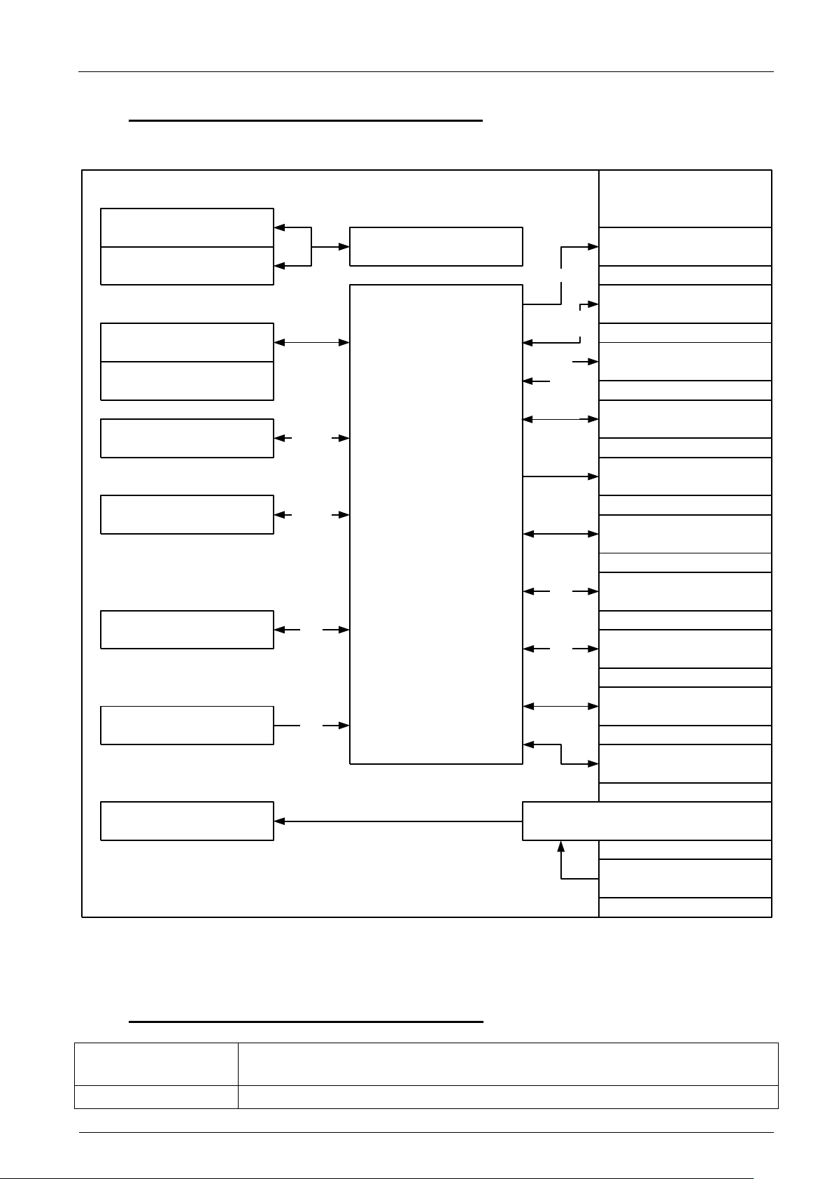
5.1. Block diagram of system components
A brief overview about all available system components is given by the succeeding block diagram.
Figure 1: Block diagram of system components
5.2. Technical data of system components
Page 11
MLC 4-xx
Technical Manual Rev. 1.2
System overview
Document: Manual_Medical_MLC_1.2
Page 11 of 37 pages
Last change date: 18-Feb-15
RAM
up to max 16GByte DDR3 1066/1333/1600 SO-DIMM in 2 sockets
Graphics
Intel HD 4600 with triple display support, base frequency 400MHz
Storage
mSATA SSD and/or 2.5” SSD/HDD connected to SATA III (6.0Gbit/s)
For available capacities please contact your PENTA representative
Note: 2.5” SSD/HDD is exchangeable by user.
Sound codec
Intel HDA compliant
OS compatibility
Intel x64 micro architecture compliant
LC Display
MLC 4-21: 21.5”/54,6cm full HD (1920x1080, 16:9), 16.7Mio colors, brightness 250 [cd/m²] with
adjustable LED backlight
Touch
Optional: 21.5”/54,6cm 5 point multitouch PCAP
Graphics interface
2x HDMI V1.4a compliant
1x VGA
USB ports
2x USB 2.0 (HighSpeed with up to 480Mbit/s)
2x USB 3.0 (SuperSpeed with up to 5Gbit/s)
Network
2x Ethernet 10/100/1000Mbit/s (10/100/1000BASE-T)
Sound
MIC IN, LINE out
COM ports
3x RS-232
Optional: 2x RS-232 galvanically isolated
Keys and signal LEDs
Power button (left side), four keys and two LEDs (right side)
Power In
Wide AC input range (110…240V~,50…60Hz)
Part number
Type
Description
5.3. Interfaces
For a more detailed description of the interfaces please refer to chapter 6. Description of interfaces.
5.4. Options
The following table show options and add on parts for the MLC:
Page 12
MLC 4-xx
Technical Manual Rev. 1.2
Description of interfaces and
functions
Document: Manual_Medical_MLC_1.2
Page 12 of 37 pages
Last change date: 18-Feb-15
Warning for medical appliances:
Accessory equipment connected to the analogue and digital interfaces must be
certified according to the respective IEC standards (e.g. IEC 950 for data processing equipment and IEC 601-1 for medical equipment). Furthermore all
configurations shall comply with the valid version of the system standard IEC
601-1-1. Everybody who connects additional equipment to the signal input part
or signal output part configures a medical system, and is therefore responsible
that the system complies with the requirements of the valid version of the system standard IEC 601-1-1. If in doubt, consult the technical service department
or your local PENTA representative.
!
10
21 3 5 76 98
11 12
4
16
17
181413 15
6. DESCRIPTION OF INTERFACES AND FUNCTIONS
This chapter provides some further information and explanations regarding the device interfaces. For
proper interface operation and handling instructions please refer also to chapter 10 Cleaning.
Note: All interface pin outs comply with the technical standards (please refer to appropriate internet
sites), deviations thereof or non-standard interfaces are documented separately.
6.1. Interfaces and controls
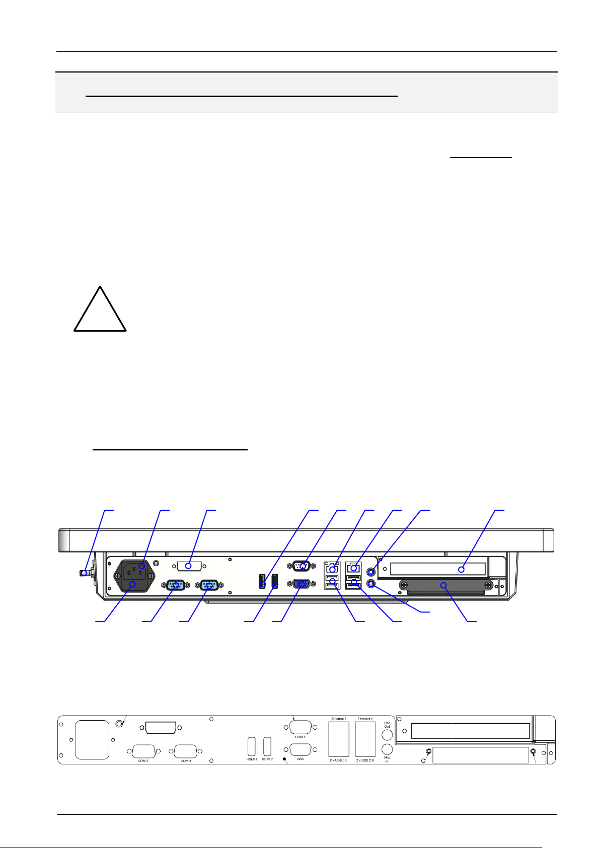
6.1.1. Location
Figure 2: Location of interfaces, bottom view without cable cover
Figure 3: Inscription of interfaces on connector/slot panel
Page 13

MLC 4-xx
Technical Manual Rev. 1.2
Description of interfaces and
functions
Document: Manual_Medical_MLC_1.2
Page 13 of 37 pages
Last change date: 18-Feb-15
Figure 4: Location of interfaces
and controls, left side view
Figure 5: Location of controls, right
side view
Figure 6: Detail right side view, keys
and LEDs
Do not connect or disconnect a powered supply cable to your PENTA device.
Attach only depowered supply cables to the PENTA device and connect the
power supply cable thereafter to the power source/outlet.
Interface #
Description
1
Potential equalization plug, 6mm, according to DIN 42801 with yellow/green
color code washer
Note: The equipment bonding terminal of the unit has to be connected to
the equipotential bonding strip (see IEC 60601-1 / EN 60601-1 or equivalent
national standards).
2
AC power input, 3pos, IEC 60320 type C14, medical version w/o Y capacitors
3
Optional DVI-D output
4 & 13
HDMI V1.4a compliant output
5
COM1, RS-232 serial port, max 115200b/s transfer speed
Note: Resources (I/O address, IRQ line) are managed via BIOS settings
20a
20b
20c
20d
20e
20f
!
6.1.2. Table of interfaces – technical data and information
Note: The numbers in the figures of the previous chapter correspond with the enumeration of the succeeding table.
Page 14

MLC 4-xx
Technical Manual Rev. 1.2
Description of interfaces and
functions
Document: Manual_Medical_MLC_1.2
Page 14 of 37 pages
Last change date: 18-Feb-15
Interface #
Description
6
LAN1, Intel I217 Ethernet controller with Intel 9.0 AMT support
LED A link/activity:
Off = no link
Yellow = network link
Blinking = data transfer
LED B link speed:
Off = 10Mbit/s
Green = 100Mbit/s
Orange =1000Mbit/s
7
LAN2, Intel I211 Ethernet controller
8
Audio Line Out (lime), headphones or speaker output interface
9
Reserved slot for PCIe add on cards, please contact your PENTA representative
for available options
10
Fuse holder with 2 fuses 5x20mm 2.0A 250V (T), high breaking capacity, replace with PENTA P/N 25.310.00006 only!
11 & 12
COM2 & 3, RS-232 serial port, max 115200b/s transfer speed
Note: Standard COM ports are indicated by metallic (silver) connector housings
Optional galvanically isolated RS-232 COM ports, max 256000b/s transfer
speed; available via USB to RS-232 converter; isolation voltage up to 4kV
Note: Galvanically isolated COM ports are indicated by plastic connector housings
Please refer to the succeeding chapter for additional information!
13 & 4
HDMI V1.4a compliant output
14
VGA output for analog monitors/displays
15
Two blue USB 3.0 SuperSpeed (5Gbit/s) ports; USB 1.1 low (1.5Mbit/s) and full
(12Mbit/s) speed compliant, USB 2.0 HighSpeed (480Mbit/s) compliant
16
Two USB 2.0 HighSpeed (480Mbit/s); USB 1.1 low (1.5Mbit/s) and full (12Mbit/s)
speed compliant
17
Audio Mic In (pink), microphone input interface
18
Slider with cover for exchangeable 2.5” HDD/SSD;
Note: If you need to exchange the HDD/SSD please contact your PENTA repre-
sentative for authorization first. Non observance may result in a loss of warranty!
BA
6.1.3. Galvanically isolated COM ports
As noted above, the galvanically isolated COM ports are provided by USB to RS-232 converters.
While the resources (I/O address, IRQ line) of standard COM ports are managed via BIOS settings,
the resources of the galvanically isolated COM ports are assigned by OS and the corresponding driver. Commonly the COM port name, used by an application/program to send and receive data, does
not match the inscription of the connector panel then.
If an application needs a dedicated COM port name (such as COM2), the name can easily be
changed via appropriate tools. For Microsoft OS please use the device manager.
Page 15

MLC 4-xx
Technical Manual Rev. 1.2
Description of interfaces and
functions
Document: Manual_Medical_MLC_1.2
Page 15 of 37 pages
Last change date: 18-Feb-15
Control #
Description
19
Main on/off switch, disconnects/connects both AC lines from/to internal PSU, switches between ACPI global states G3 (mechanical off)
and G2 (soft off)
Note: ACPI global state G2 is the same as ACPI system state S5
Push button is indicated by symbol shown right:
20
Membrane keyboard with four keys and two LEDs
20a
Power push-button (soft on/off)
turns on/off device if main on/off switch #19 connects internal PSU to AC
lines, with other words: Power push-button switches device between ACPI
system state G2/S5 (soft off) and S0 (working)
forces device to resume from ACPI system state S4 (STD, Suspend To
Disk) depending on OS settings
Press button minimum 2s to turn on device and minimum 7s to hard power
down.
Note: This feature avoids unintended power ups/downs
20b
Brightness increase button, increases LCD backlight brightness if pressed
20c
Brightness decrease button, decreases LCD backlight brightness if pressed
20d
Touch on/off button, disables/enables the touch screen if pressed, useful if touch
should be disabled for cleaning purposes to avoid undesired operation of device
20e
Blue LED indicates that
device is in ACPI state S0 (powered and full working, LCD on) or
device is in ACPI state S0 “away mode” (only LCD is off) or
device is in ACPI state S1 (CPU is in HALT state, LCD off)
For technicians: PSU powers all supply rails
20f
Orange LED indicates that
device is in ACPI state S3 (STR, Suspend To RAM, LCD off) or
device is in ACPI state S4 (STD, Suspend To Disk) or
device is in ACPI state S5 (soft off)
For technicians: PSU provides only +5V standby voltage
w/o
Optional PCAP touch; the MLC is available as touch version, too.
Note: This is no add-on option and has to be ordered, please contact your PEN-
TA sales representative for this purpose.
Exchange fuses only if PENTA device is depowered and not connected to the
power source/outlet.
!
6.1.4. Table of controls – technical data and information
6.1.5. Exchanging Fuses
Page 16

MLC 4-xx
Technical Manual Rev. 1.2
Description of interfaces and
functions
Document: Manual_Medical_MLC_1.2
Page 16 of 37 pages
Last change date: 18-Feb-15
Exchange defective fuses only with specified type.
Refer to chapter 6.1.2 Table of interfaces – technical data and information
Step
#
Image
Description
1
w/o
Remove power supply cable
2
Insert a small screw driver or similar
into the fuse holder notch
Pull out the fuse holder carefully
3
Rotate fuses sideways
!
To exchange the fuses, proceed with the following steps:
Page 17

MLC 4-xx
Technical Manual Rev. 1.2
Description of interfaces and
functions
Document: Manual_Medical_MLC_1.2
Page 17 of 37 pages
Last change date: 18-Feb-15
Step
#
Image
Description
4
Remove defective fuses
5
Insert new fuses
6
Snap in new fuses
Page 18

MLC 4-xx
Technical Manual Rev. 1.2
Description of interfaces and
functions
Document: Manual_Medical_MLC_1.2
Page 18 of 37 pages
Last change date: 18-Feb-15
Step
#
Image
Description
7
Insert and press fuse holder firmly until
fuse holder snaps into power entry
module
Page 19

MLC 4-xx
Technical Manual Rev. 1.2
BIOS configuration overview
Document: Manual_Medical_MLC_1.2
Page 19 of 37 pages
Last change date: 18-Feb-15
7. BIOS CONFIGURATION OVERVIEW
7.1. Default settings
If BIOS settings are misconfigured and the MLC therefor behaves unexpected, restore the BIOS de-
fault settings.
1. Boot MLC and press <DEL> key on POST/boot logo screen short after keyboard is initialized
(indicated by flashing keyboard LEDs), then
2. press <F3> key
3. press <ENTER> key
4. press <F4> key
5. press <ENTER> key again
MLC reboots with BIOS default settings.
Note: This procedure works even if the display output stays dark and the BIOS itself is not corrupted.
7.2. Enable ACPI S3 state
The BIOS default values set the deepest CPU sleep mode to S1 only. This prevents an OS from setting the MLC into S3 (Suspend To RAM) which results in higher power consumption.
To save energy, enable S3 via BIOS setting.
1. Boot MLC and press <DEL> key on POST/boot logo screen short after keyboard is initialized
(indicated by flashing keyboard LEDs), then
2. move with cursor keys to Advanced
3. move with cursor keys to and press <ENTER> key
4. option S1 only(CPU Stop Clock) is set, press <ENTER> key
5. move with cursor keys to option S3 only(Suspend To RAM)
6. press <ENTER> key to select and confirm
7. press <F4> key
8. press <ENTER> key to save settings and reboot MLC
7.3. Enable PXE/network boot
Sometimes it might be necessary to boot the MLC from a network. To enable the Pre-Boot-Execution
(PXE) ROM for the integrated Ethernet ports and set the proper boot sequence, proceed with the following steps:
1. Boot MLC and press <DEL> key on POST/boot logo screen short after keyboard is initialized
(indicated by flashing keyboard LEDs), then
2. move with cursor keys to Boot
3. move with cursor keys to Launch PXE OpROM and press <ENTER> key
Page 20

MLC 4-xx
Technical Manual Rev. 1.2
BIOS configuration overview
Document: Manual_Medical_MLC_1.2
Page 20 of 37 pages
Last change date: 18-Feb-15
4. move with cursor keys to option Enabled and press <ENTER> key
5. move with cursor keys to Boot Option #1 and press <ENTER> key
6. move with cursor keys to option Disabled and press <ENTER> key
7. disable all other boot devices if listed
8. press <F4> key
9. press <ENTER> key to save settings and reboot MLC
MLC should now reboot and connect to network.
Note: Make sure that the necessary services and servers are available in your network environment.
7.4. Changing boot device order
As default an integrated storage medium is set as primary boot device. It might be necessary to boot
from another device such as USB sticks or USB CD/DVD drives to install an OS or for maintenance
purposes. In this case, the boot order has to be changed.
1. Attach possible/desired boot device(s)
2. boot MLC and press <DEL> key on POST/boot logo screen short after keyboard is initialized
(indicated by flashing keyboard LEDs), then
3. move with cursor keys to Boot
4. move with cursor keys to Boot Option #1 and press <ENTER> key
5. select one of the listed boot devices with cursor keys and press <ENTER> key
6. if boot device is not listed press <ESC> key
7. move with cursor keys to Hard Drive BBS Priorities and press <ENTER> key
8. move with cursor keys to Boot Option #1 and press <ENTER> key
9. select one of the listed boot devices with cursor keys and press <ENTER> key
10. press <ESC> key and check Boot Option #1 for correct boot device
11. press <F4> key
12. press <ENTER> key to save settings and reboot MLC
MLC should now reboot from selected boot device.
Note: If selected device is not bootable, the MLC boots from the next device of the BIOS boot list. To
boot from the internal storage medium, just remove all attached boot devices or use previous procedure to set the internal storage medium as Boot Option #1.
Page 21

MLC 4-xx
Technical Manual Rev. 1.2
PENTA software
Document: Manual_Medical_MLC_1.2
Page 21 of 37 pages
Last change date: 18-Feb-15
8. PENTA SOFTWARE
For installation and usage of available PENTA add on software and tools please afford and
refer to the corresponding PENTA software (product) manual.
Page 22

MLC 4-xx
Technical Manual Rev. 1.2
Specifications
Document: Manual_Medical_MLC_1.2
Page 22 of 37 pages
Last change date: 18-Feb-15
9. SPECIFICATIONS
9.1. Mechanical specifications MLC 4-21
9.1.1. Dimensions front and side view
Figure 7: MLC 4-21, dimensions front and side view
9.1.2. Dimensions rear view
Figure 8: MLC 4-21, dimensions rear view with VESA 100 mounting holes (M8 threads)
Page 23

MLC 4-xx
Technical Manual Rev. 1.2
Specifications
Document: Manual_Medical_MLC_1.2
Page 23 of 37 pages
Last change date: 18-Feb-15
Rated voltage range
110…240V~ single phase
Rated frequency range
50…60Hz
Maximum voltage range
90…264V~ single phase
Maximum frequency range
47…63Hz
Fuse rating
T 2.0A H 250V
Test # ACPI
state
P
avg
[W]
Remark
1
G5
0
Mechanical off
2
S5
2.5
Soft off
3
S0
34
W7 x64 desktop/idle mode, max LCD brightness
4
S0
23
W7 x64 desktop/idle mode, min LCD brightness
5
S0
18
W7 x64 desktop/idle mode, LCD off, “away mode”
6
S0
66
(max 78)
W7 x64 benchmark (100% load for CPU/RAM/mSATA/2D &
3D graphic/2x NIC), max LCD brightness
7
S0
56
(max 63)
W7 x64 benchmark (100% load for CPU/RAM/mSATA/2D &
3D graphic/2x NIC), min LCD brightness
8
S0
51
(max 54)
W7 x64 benchmark (100% load for CPU/RAM/mSATA/2D &
3D graphic/2x NIC), LCD off, “away mode”
9
S1
23
CPU in HALT state, LCD off
10
S3
4
STR (Suspend To RAM)
11
S4
3.5
STD (Suspend To Disk)
9.1.3. Weight
Maximum 8.5kg; measurement includes mSATA and HDD parts and optional galvanically isolated
COM ports.
9.2. Electrical specifications
9.2.1. AC input
9.2.2. Power consumption MLC 4-21
Tested configuration:
Intel Core i7-4700EQ, clock speed 2.4GHz, 2x 8GB RAM, 64GB mSATA, 500GB HDD, 2x galvanically isolated RS-232 ports, USB keyboard with integrated track ball attached (~0.5W)
Page 24

MLC 4-xx
Technical Manual Rev. 1.2
Specifications
Document: Manual_Medical_MLC_1.2
Page 24 of 37 pages
Last change date: 18-Feb-15
Operating ambient temperature range
0°C…+40°C
Storage ambient temperature range
-10°C...+60°C
Operating ambient humidity range
10%...90% (non condensing)
Storage ambient humidity range
5%...95% (non condensing)
Ambient air pressure operating
700hPa…1060hPa
Front, rear, left/right side and top
IP65
Bottom interface side w/o cable cover
IP20
Bottom interface side with cable cover
IP54
9.3. Environmental specifications
The MLC 4-xx is reliable and best operated/stored under the following recommended conditions:
9.3.1. IP rating
9.4. Labels
9.4.1. Serial number label
The MLC is labelled on its back side. The label complies in detail with the following example layout.
Figure 9: Information on S/N label
Page 25

MLC 4-xx
Technical Manual Rev. 1.2
Specifications
Document: Manual_Medical_MLC_1.2
Page 25 of 37 pages
Last change date: 18-Feb-15
Symbol
Meaning/explanation
Read operating instructions/manual
Observe warnings, handling and safety instructions
Do not dispose this device or parts of it! Observe the valid national and local
regulations for disposal.
For further information, refer to:
DIRECTIVE 2002/96/EC OF THE EUROPEAN PARLIAMENT AND OF THE
COUNCIL of 27 January 2003 on waste electrical and electronic equipment
(WEEE)
CE mark, confirms that device complies with all applicable norms, regulations
and directives
Year (YYYY) and month (MM) of manufacturing/placing on the market
YYYY-MM
9.4.2. Explanation of serial number label symbols
9.4.3. Fuse label
The fuse label is located below interface #10, please refer to 6.1.2 Table of interfaces – technical data
and information, too.
Figure 10: Fuse label
Page 26

MLC 4-xx
Technical Manual Rev. 1.2
Cleaning & desinfecting
Document: Manual_Medical_MLC_1.2
Page 26 of 37 pages
Last change date: 18-Feb-15
Electric shock hazard. Before cleaning the MLC, disconnect the power cord to
the device.
!
10. CLEANING & DESINFECTING
PENTA recommends product cleaning and disinfecting according to the guidelines and specifications
of the German Robert Koch-Institute (RKI). These guidelines apply to the MLC only. For cables, sensors and other peripheral items, follow the cleaning instructions in the Directions for Use document
that accompany these accessories.
The following germicidal products are PENTA approved disinfectants for use on your PENTA product,
especially for the touchscreen or glass front:
Incidin plus
Skinmansoft
Cutasept G. & F.
Sterilium
Aseptoman
Use a spray applicator, apply any of the approved liquids from the list and use a soft lint free cloth to
clean the screen. Follow the cleaning agent manufacturer guidelines.
While there are many other options for disinfecting PENTA products, PENTA may not have tested the
effectiveness of these products on your PENTA product. If you use a product or method other than
those that we’ve recommend above, you should document accordingly in your cleaning protocol.
Please contact your local PENTA partner for the approval of further germicides and detergents.
Note: Disinfect according to your facility's procedures and local regulations.
As a general safety precaution, your PENTA product should undergo decontamination before return-
ing the device to PENTA for service, repair, inspection or disposal.
Note: Contaminated items must not be returned without prior, written agreement!
Page 27

MLC 4-xx
Technical Manual Rev. 1.2
Cleaning & desinfecting
Document: Manual_Medical_MLC_1.2
Page 27 of 37 pages
Last change date: 18-Feb-15
Electric shock hazard. DO NOT autoclave the MLC. The device and accessories are not autoclaveable.
Never wet the MLC or immerse it in fluid of any kind. Never allow liquid to enter
the device.
!
!
Page 28

MLC 4-xx
Technical Manual Rev. 1.2
Common warnings, handling
and safety instructions
Document: Manual_Medical_MLC_1.2
Page 28 of 37 pages
Last change date: 18-Feb-15
Although your PENTA device is resistant against a lot of aggressive chemicals,
some of them like acids and others can damage the housing, the seals and
your display or touch panel. Please ask your local PENTA (sales) representative for further information.
The touch panel it will only operate with your fingers or a special input pen.
Never use hard, sharp, pointed, wooden, metal, plastic… devices, pencils,
pens, knives ….. They will destroy your touch panel.
Never shock, hit, overheat, burn, scratch, smash … your PENTA device. This
will destroy your PENTA device or parts thereof.
The administrator password for the used operating system and/or BIOS is very
important! The loss of the password can cause data loss or will heavily influence the software installation of your system.
Because the administrator password is the main key for your system (access
to all data, possibility to change all options … ) it is very important, that only
authorized persons will have access to this password!
Invalid changes of BIOS settings can make your system useless or will cause
data loss and/or hardware damage!
Any damages and/or problems caused through invalid BIOS changes will not
be covered by warranty!
Computer components are highly sensitive devices. ESD and wrong treatment
can damage and destroy your DEVICE and / or your add-on cards.
Only qualified personnel should handle your computer hardware.
Beware from ESD – ground yourself and your hardware first!
!!!!!
!
11. COMMON WARNINGS, HANDLING AND SAFETY INSTRUCTIONS
Page 29

MLC 4-xx
Technical Manual Rev. 1.2
Common warnings, handling
and safety instructions
Document: Manual_Medical_MLC_1.2
Page 29 of 37 pages
Last change date: 18-Feb-15
Never wet the PENTA device or immerse it in fluid of any kind. Never allow
liquid to enter the device.
If you transport the device in a vehicle, it is the sole responsibility of the driver
to drive the vehicle safely. Adequately secure the device in the vehicle to prevent injuries or other damage in the event of an accident. The driver is always
responsible for the safety of the vehicle. PENTA assumes no responsibility for
accidents or collisions.
Do not place and/or mount your PENTA device on cards, trolleys, surfaces,
vehicles, cabinets or tables that for reasons of weight or stability are unsuitable
for this purpose.
Adequately secure the device to prevent injuries or other damage in the event
of unexpected movement and impacts. Ask your local PENTA partner for more
information about suitable mountings and fastenings.
Once the lifetime of your PENTA device has ended, the device must not be
disposed in the standard domestic refuse. National waste disposal regulations
must be observed.
Please contact your local PENTA partner for dispose of the device.
Please be aware that in the event of a fire, toxic substances (gases, liquids,
etc.) that may be hazardous to your health may escape from your PENTA device.
As with all industrially manufactured goods, the use of substances that induce
an allergic reaction (e.g. nickel, aluminum) cannot be generally excluded. If you
develop an allergic reaction (such as a skin rash, frequent sneezing, red eyes
or respiratory difficulties), consult a physician immediately to determine the
cause.
!
!!!!!
Page 30

MLC 4-xx
Technical Manual Rev. 1.2
Common warnings, handling
and safety instructions
Document: Manual_Medical_MLC_1.2
Page 30 of 37 pages
Last change date: 18-Feb-15
No modification of this device is allowed!
To separate the device completely from the mains power supply, pull the plug
out of the mains socket at the back side of the unit. Make sure, that the back
side of the device will be accessible at any time.
Note: If optional cable cover is mounted, ensure that the power cord is accessible/removable from the power outlet.
To avoid risk of electric shock, this equipment must only be connected to supply mains with protective earth!
To avoid influences between present equipment and the PENTA device
caused by electromagnetic phenomena, refer to chapter 13.1 EN 60601-1-2
tables; this appendix documents ambient conditions to be considered for save
and reliable operation.
To avoid risks for patients that may arise due to a direct contact to the device,
take care, that the minimum distance of 1.5m between the device and a patient
is always kept.
!!!!!
Page 31

MLC 4-xx
Technical Manual Rev. 1.2
Certifications and Norms
Document: Manual_Medical_MLC_1.2
Page 31 of 37 pages
Last change date: 18-Feb-15
12. CERTIFICATIONS AND NORMS
12.1. Declaration of conformity
Figure 11: Declaration of Conformity, excerpt from original document
Page 32

MLC 4-xx
Technical Manual Rev. 1.2
Certifications and Norms
Document: Manual_Medical_MLC_1.2
Page 32 of 37 pages
Last change date: 18-Feb-15
12.2. EMC test compliance
12.2.1. Summary for all EMC tests
Figure 12: EMC test summary, excerpt from original document
Page 33

MLC 4-xx
Technical Manual Rev. 1.2
Appendix
Document: Manual_Medical_MLC_1.2
Page 33 of 37 pages
Last change date: 18-Feb-15
The MLC 4-xx is intended for use in the electromagnetic environment specified below. The customer or the user of the device should assure that it is used in such an
environment.
Emissions Test
Device compliance to
IEC/EN 60601-1-2:2007
(3rd edition)
Device compliance to
IEC/EN 60601-1-2:2014
(4th edition)
Electromagnetic Environment - Guidance
RF Emissions
CISPR 11 (modified)
Group 1
Group 1
The device uses RF energy only for its internal function. Therefore, its RF
emissions are very low and are not likely to cause any interference in nearby
electronic equipment.
RF Emissions
EN55011
Class B
Class B
The device is suitable for use in all establishments, including domestic establishments and those directly connected to the public low-voltage power supply
network that supplies buildings used for domestic purposes.
Harmonic emissions
IEC 61000-3-2
Fulfilled
Fulfilled
Voltage fluctuations/flicker emissions
IEC 61000-3-3
Fulfilled
Fulfilled
13. APPENDIX
13.1. EN 60601-1-2 tables
13.1.1. Guidance and manufacturer’s declaration – electromagnetic emissions (IEC 60601-1-2:2007 Table 1)
Page 34

MLC 4-xx
Technical Manual Rev. 1.2
Appendix
Document: Manual_Medical_MLC_1.2
Page 34 of 37 pages
Last change date: 18-Feb-15
The MLC 4-xx is intended for use in the electromagnetic environment specified below. The customer or the user of the device should assure that it is used in such an
environment.
Immunity Test
IEC/EN 60601-1-2:2007
(3rd edition) Test Level
IEC 60601-1-2:2014
(4th edition) Test Level
Device complies to
Electromagnetic Environment - Guidance
Electrostatic discharge (ESD)
IEC 61000-4-2
±6kV contact
±8kV air
±8kV contact
±15kV air
IEC/EN 60601-1-2:2007
IEC 60601-1-2:2014
Contact discharge criterion C
Air discharge criterion A
Floors should be wood, concrete, or ceramic tile. If floors are covered with synthetic material, the relative humidity should
be at least 30%.
Electrical fast transients / Burst
IEC 61000-4-4
±2kV on power supply lines,
5kHz repetition
±1kV for input/output lines
±2kV on power supply lines,
100kHz repetition
±1kV for input/output lines,
100kHz repetition
IEC/EN 60601-1-2:2007
IEC 60601-1-2:2014
Mains power quality should be that of a
typical commercial or hospital environment.
Surge
IEC 61000-4-5
±1kV differential on AC power
supply lines
±2kV common mode
±(500V, 1kV & 2kV) differential
on AC power supply lines > 3m
±(500V, 1kV & 2kV) common
mode
±2kV common mode (outdoor
cables)
IEC/EN 60601-1-2:2007
IEC 60601-1-2:2014
Mains power quality should be that of a
typical commercial or hospital environment.
Power frequency magnetic field
IEC 61000-4-8
50 and 60Hz
3A/m
50 and 60Hz
30A/m
IEC/EN 60601-1-2:2007
IEC 60601-1-2:2014
Power frequency magnetic fields should
be at levels characteristic of a typical location in a typical commercial or hospital
environment.
Voltage dips and voltage variations on power supply input lines
IEC 61000-4-11
Dip to 40% for 5 cycles (100ms)
Dip to 70% for 25 cycles (500ms)
Dip to 0% for 1 cycles @
0°phase angle
Dip to 70% for 25/30 cycles @ 0°
phase angle
IEC/EN 60601-1-2:2007
IEC 60601-1-2:2014
Mains power quality should be that of a
typical commercial or hospital environment. If the user of the device requires
continued operation during power mains
interruptions, it is recommended that the
device is powered from an uninterruptible
power supply or a battery.
13.1.2. Guidance and manufacturer’s declaration – electromagnetic immunity – for all EQUIPMENT and SYSTEMS (IEC 60601-12:2007 Table 2)
Page 35

MLC 4-xx
Technical Manual Rev. 1.2
Appendix
Document: Manual_Medical_MLC_1.2
Page 35 of 37 pages
Last change date: 18-Feb-15
The MLC 4-xx is intended for use in the electromagnetic environment specified below. The customer or the user of the device should assure that it is used in such an
environment.
Immunity Test
IEC/EN 60601-1-2:2007
(3rd edition) Test Level
IEC 60601-1-2:2014
(4th edition) Test Level
Device complies to
Electromagnetic Environment - Guidance
Short interruptions on power
supply input lines
IEC 61000-4-11
Dropout to 5% for 10ms
Interrupt > 95% for 5s
Dropout to 0% for 0.5 cycles @
0°, 45°, 90°, 135° , 180°, 225°,
270° & 315° phase angles
Interrupt 100% for 250/300 cycles
IEC/EN 60601-1-2:2007
IEC 60601-1-2:2014
Dropout criterion A
Interrupt 5s criterion C
Mains power quality should be that of a
typical commercial or hospital environment. If the user of the device requires
continued operation during power mains
interruptions, it is recommended that the
device is powered from an uninterruptible
power supply or a battery.
Page 36

MLC 4-xx
Technical Manual Rev. 1.2
Appendix
Document: Manual_Medical_MLC_1.2
Page 36 of 37 pages
Last change date: 18-Feb-15
The MLC 4-xx is intended for use in the electromagnetic environment specified below. The customer or the user of the device should assure that it is used in such an
environment.
Immunity Test
IEC/EN 60601-1-2:2007
(3rd edition) Test Level
IEC 60601-1-2:2014
(4th edition) Test Level
Device complies to
Electromagnetic Environment - Guidance
Radiated RF
IEC 61000-4-3
3V/m, 80-2500MHz, 1kHz/2Hz
80%AM modulation
10V/m, 80-2500MHz, 1kHz/2Hz
80%AM modulation for life support equipment
Dwell Time is 3 seconds for 2Hz
modulation
Dwell Time is 1 second for 1kHz
modulation
3V/m, 80-2700MHz, 1kHz
80%AM modulation for Professional Healthcare Facility Environment
10V/m, 80-2700MHz, 1kHz
80%AM modulation for Home
Healthcare Environment
IEC/EN 60601-1-2:2007
Life support equipment
IEC 60601-1-2:2014
Home Healthcare Environment
Portable and mobile RF communications
equipment should be used no closer to
any part of the device, including cables,
than the recommended separation distance calculated from the equation applicable to the frequency of the transmitter.
Recommended separation distance:
𝑑 = 1.2 ×
√
𝑃 from 150kHz to 80MHz
𝑑 = 1.2 ×
√
𝑃 from 80MHz to 800MHz
𝑑 = 2.3 ×
√
𝑃 from 800MHz to 2.5GHz
where P is the maximum output power
rating of the transmitter in watts (W) according to the transmitter manufacturer
and d is the recommended separation
distance in meters (m).
Field strengths from fixed RF transmitters,
as determined by an electromagnetic site
survey [a], should be less than the compliance level in each frequency range [b].
Interference may occur in the vicinity of
equipment marked with the following symbol:
Conducted RF
IEC 61000-4-6
3Vrms, 0.15-80 MHz, 1kHz/2Hz
80% AM modulation
3Vrms, 0.15-80 MHz, 1kHz/2Hz
80% AM modulation for life support equipment
3Vrms, 0.15-80 MHz, 1kHz 80%
AM modulation
6Vrms in ISM bands (I/O cables
< 3m excluded)
10Vrms
IEC/EN 60601-1-2:2007
IEC 60601-1-2:2014
NOTE 1 - At 80 MHz and 800 MHz, the higher frequency range applies.
NOTE 2 - These guidelines may not apply in all situations. Electromagnetic propagation is affected by absorption and reflection from structures, objects and people.
13.1.3. Guidance and manufacturer’s declaration - electromagnetic immunity - for EQUIPMENT and SYSTEM that are not LIFESUPPORTING (IEC 60601-1-2:2007 Table 4)
Page 37

MLC 4-xx
Technical Manual Rev. 1.2
Appendix
Document: Manual_Medical_MLC_1.2
Page 37 of 37 pages
Last change date: 18-Feb-15
[a] = Field strengths from fixed transmitters, such as base stations for radio (cellular/cordless) telephones and land mobile radios, amateur radio, AM and FM radio broadcast and TV
broadcast cannot be predicted theoretically with accuracy. To assess the electromagnetic environment due to fixed RF transmitters, an electromagnetic site survey should be considered. If the measured field strength in the location in which the device is used exceeds the applicable RF compliance level above, the device should be observed to verify normal operation. If abnormal performance is observed, additional measures may be necessary, such as re-orienting or relocating the device.
[b] = Over the frequency range 150 kHz to 80 MHz, field strengths should be less than 3V/m.
The device is intended for use in an electromagnetic environment in which radiated RF disturbances are controlled. The customer or the user of the device can help prevent electromagnetic interference by maintaining a minimum distance between portable and mobile RF communications equipment (transmitters) and the device as recommended below, according to the maximum output power of the communications equipment.
Rated maximum output power of transmitter [W]
Separation distance according to frequency of transmitter [m]
150kHz to 80MHz
𝑑 = 1.2 ×√𝑃
80MHz to 800MHz
𝑑 = 1.2 ×√𝑃
800MHz to 2.5GHz
𝑑 = 2.3 ×√𝑃
0.01
0.12
0.12
0.23
0.1
0.37
0.37
0.74
1
1.17
1.17
2.33
10
3.69
3.69
7.38
100
11.67
11.67
23.33
For transmitters rated at a maximum output power not listed above, the recommended separation distance d in meters [m] can be estimated using the equation applicable to the frequency of the transmitter, where P is the maximum output power rating of the transmitter in watts [W] according to the transmitter manufacturer.
NOTE 1 - AT 80 MHz and 800 MHz, the separation distance for the higher frequency range applies.
NOTE 2 - These guidelines may not apply in all situations. Electromagnetic propagation is affected by absorption and reflection from structures, objects, and people.
13.1.4. Recommended separation distances between portable and mobile RF communications equipment and the MLC 4-xx
(IEC 60601-1-2:2007 Table 6)
 Loading...