

Page 1

MIX-220
Embedded Computer System with
MI-220 Mini-ITX Motherboard
User’s Manual
Manual Rev.: 2.00
Revision Date: June 4, 2012
Part No: 50-1Z126-1000
Advance Technologies; Automate the World.
Page 2

Revision History
Revision Release Date Description of Change(s)
2.00 2012/06/04 Initial release
ii Revision History
Page 3

MIX-220
Preface
Copyright 2012 ADLINK Technology Inc.
This document contains proprietary infor mation protected by copyright. All rights are reserved. No part of this manual may be reproduced by any mechanical, electronic, or other means in any form
without prior written permission of the manufacturer.
Disclaimer
The information in this document is subject to change without prior
notice in order to improve reliability, design, and function and does
not represent a commitment on the part of the manufa cturer.
In no event will the manufacturer be liable for direct, indirect, special, incidental, or consequential damages arising out of the use or
inability to use the product or documentation, even if advised of
the possibility of such damages.
Environmental Responsibility
ADLINK is committed to fulfill its social responsibility to global
environmental preservation through compliance with the European Union's riction of Hazardous Substances (RoHS) directive
and Waste Electrical and Electronic Equipment (WEEE) directive.
Environmental protection is a top priority for ADLINK. We have
enforced measures to ensure that our products, manufacturing
processes, components, and raw materials have as little impact on
the environment as possible. When products are at their end of
life, our customers are encouraged to dispose of them in accordance with the product disposal and/or recovery programs prescribed by their nation or company.
Trademarks
Product names mentioned herein are used for identification purposes only and may be trademarks and/or registered trademarks
of their respective companies.
Preface iii
Page 4

Using this Manual
Audience and Scope
The MIX-220 User’s Manual is intended for hardware technicians
and systems operators with knowledge of installing, configuring
and operating embedded single board computers.
Manual Organization
This manual is organized as follows:
Preface: Presents copyright notifications, disclaimers, trade-
marks, and associated information on the proper usage of this
document and its associated product(s).
Chapter 1, Introduction: Introduces the MIX-220, its features,
specifications and mechanical dimensions.
Chapter 2, Getting Started: Presents information on chassis layout, setup and operation of the MIX-220.
Chapter 3, Hardware Information: Provides
fan removal/replacement, connectors and pin assignments
information about
.
Important Safety Instructions: Presents safety instructions all
users must follow for the proper setup, installation and usage of
equipment and/or software.
Getting Service: Contact information for ADLINK’s worldwide
offices.
iv Preface
Page 5

MIX-220
Conventions
Take note of the following conventions used throughout this
manual to make sure that users perform certain tasks and
instructions properly.
Additional information, aids, and tips that help users perform
tasks.
NOTE:
NOTE:
Information to prevent minor physical injury, component damage, data loss, and/or program corruption when trying to com-
CAUTION:
WARNING:
plete a task.
Information to prevent serious physical injury, component
damage, data loss, and/or program corruption when trying to
complete a specific task.
Preface v
Page 6

This page intentionally left blank.
vi Preface
Page 7

MIX-220
Table of Contents
Revision History...................................................................... ii
Preface.................................................................................... iii
List of Figures........................................................................ ix
List of Tables.......................................................................... xi
1 Introduction ........................................................................ 1
1.1 Overview.............................................................................. 1
1.2 Features............................................................................... 2
1.3 Specifications....................................................................... 3
1.4 Mechanical Drawing ............................................................ 5
2 Getting Started ................................................................... 7
2.1 Packing List ......................................................................... 7
2.2 Chassis Layout .................................................................... 8
2.3 Installing the CPU.............................................................. 12
2.4 Installing the CPU Cooler .................................................. 14
2.1 Installing the CPU Cooler .................................................. 14
2.5 System Memory................................................................. 15
2.6 SATA Drive Installation.................... .... ... ... ... ... .... ... ... ... .... . 16
2.7 Installing PCIe/PCI Cards.................................................. 20
2.8 Wall Mount Brackets..................... ... .... ... ... ... ... .... ... ... ... ..... 21
2.9 Powering Up...................................................................... 22
2.10 Driver Installation................................................. ... ... ... .... . 23
3 Hardware Information...................................................... 25
3.1 Fan Removal and Replacement ........................................ 25
3.2 I/O Connector Pin Definitions .......................... .... ... ... ... .... . 28
vii
Page 8

Important Safety Instructions............................................... 33
Getting Service...................................................................... 35
viii
Page 9

MIX-220
List of Figures
Figure 1-1: MIX-220 Dimensions (without wall mount brackets)........5
Figure 1-2: MIX-220 Dimensions (with wall mount brackets).............6
Figure 2-1: MIX-220 Front/Rear Panel...............................................8
Figure 2-2: MIX-220 Drive Bay and Fan Access................................9
List of Figures ix
Page 10

This page intentionally left blank.
xList of Figures
Page 11

MIX-220
List of Tables
Table 1-1: MIX-220 General Specifications......................................4
List of Tables xi
Page 12

This page intentionally left blank.
xii List of Tables
Page 13

1 Introduction
This chapter will introduce the MIX-220, its features, specifications, and mechanical layout. For detailed information on the
MI-220 Mini-ITX industrial motherboard, refer to the user manual
downloadable from the ADLINK website:
http://www.adlinktech.com/PD/web/PD_detail.ph p?cKind=&pid=1014
1.1 Overview
The MIX-220 is an embedded computer system based on the
MI-220 Mini-ITX form factor industrial motherboard supporting
32nm process quad/dual-core Intel® Core™ i7/i5/i3 and Celeron®
processors, Intel® QM67 Express chipset and Dual Channel
DDR3 1066/1333MHz (up to 8GB) in two SODIMM slots. Features
include integrated Intel® HD Graphics (VGA, DVI-D, HDMI outputs), dual Gigabit Ethernet, six USB 2.0 ports, four serial ports
(1x RS-232/422/485, 3x RS-232), and an externally accessible
anti-shock drive bay for two 2.5” SATA 6Gb/s drives.
The MIX-220 provides a PCIe x16 slot and PCI slot with card
holder for add-on cards up to 190mm in length, and a PCI Express
Mini Card slot for SSD or Wi-Fi module. Active cooling is provided
by dual 6cm fans with air filters that are easily accessible for
cleaning or replacement, and wall mount brackets allow for flexible
installation.
MIX-220
Introduction 1
Page 14

1.2 Features
X Embedded computer system (330 mm x 212 mm x 88 mm)
X Supports Intel® Core™ i7/i5/i3 and Celeron® processors,
rPGA988B package in Socket G2
X Integrated Intel® HD Graphics with VGA, DVI-D, HDMI out-
puts (features dependent on CPU model)
X 2x GbE (Intel® 82579LM, 82574L controllers)
X 6x USB 2.0 ports (2x front, 4x rear)
X Anti-shock drive bay for two 2.5” SATA 6Gb/s drives
X Four serial ports (1x RS-233/422/485, 3x RS-233)
X PCIe x16 slot, PCI slot, PCI Express Mini Card slot
X HD audio with Mic, Line In, Line Out
X Dual 6cm fans with air filters
X 250W FlexATX AC power supply
X Wall mount brackets
X Mounting point for Wi-Fi antenna
X RoHS compliant
2Introduction
Page 15

MIX-220
1.3 Specifications
System
CPU • Intel® Core™ i7-2710QE, 2.1GHz, 6M L2 Cache, 32nm,
45W TDP
• Intel® Core™ i5-2510E, 2.5GHz, 3M L2 Cache, 32nm,
35W TDP
• Intel® Core™ i3-2330E, 2.2GHz, 3M L2 Cache, 32nm,
35W TDP
• Intel® Celeron® B810, 1.6GHz, 2M L2 Cache, 32nm,
35W TDP
Chipset • Intel® QM67 Express Chipset
Memory • Dual-Channel DDR3 1066/1333MHz, 2x 204-pin
SO-DIMM sockets, up to 8GB
BIOS • AMI BIOS with 32 Mb SPI flash memory
Graphics • Integrated Intel® HD Graphics (features dependent on
CPU model)
Ethernet • 2x GbE (Intel® 82579LM, 82574L controllers)
• Wake on LAN supported
Audio • Realtek ALC892 HD audio
Watchdog Timer • 1-255 second/minute programmable
Hardware Monitor • CPU temperature and supply voltages
Operating System • Windows XP/7 32/64-bit, Fedora 14,
Red Hat Enterprise Linux 5
I/O Interfaces
Front I/O • 2x USB 2.0 ports
Rear I/O • 2x RJ-45 LAN ports
• 4x USB 2.0 ports
• 1x DB-15 VGA connector
• 1x DVI-I connector (DVI-D signals only)
• 1x HDMI type A connector,
• 4x serial port connectors
• 3.5mm jacks for line-in, line-out and mic-in
• 1x PCI expansion slot
• 1x PCIe expansion slot
LEDs/Switches • Power , HDD (drive activity)
• On/Off button
• Reset button (recessed)
Introduction 3
Page 16
Power Requirements
Input • 100-240 VAC universal
Mode •ATX power
Mechanical and Environment
Dimensions • 330 mm x 212 mm x 88 mm (W x D x H)
Operating Temp. • 0°C to 50°C
Storage Temp. • -20ºC to 75ºC
Rel. Humidity • 10% to 90%, non-condensing
Certifications • CE, FCC Class A
T able 1-1: MIX-220 General Specifications
4Introduction
Page 17

1.4 Mechanical Drawing
Rear View
MIX-220
233.2
Le View Right View
87.2
93.6
Top View
330
Front View
221.2
Dimensions in mm
Figure 1-1: MIX-220 Dimensions (without wall mount brackets)
Introduction 5
Page 18

Rear View
380
360
140
233.2
Le View Right View
87.2
92.2
Top View
330
180
221.2
Front View
Dimensions in mm
Figure 1-2: MIX-220 Dimensions (with wall mount brackets)
6Introduction
Page 19

2 Getting Started
The following chapter describes how to set up the MIX-220.
2.1 Packing List
Unpack the contents of the shipping carton. Please check that
your package contains the items below. If you discover damaged
or missing items, please contact your vendor.
Z MIX-220 Embedded Computer System
Z Accessory kit: drive bay mounting hardware, wall mount
brackets, AC power cord (US)
Z Driver CD
Z MI-220 Motherboard Quick Reference Guide
DO NOT install or apply power to equipment that is damaged
or if there is missing/incomplete equipment. Retain the ship-
WARNING:
ping carton and packing materials for inspection. Please contact your ADLINK dealer/vendor immediately for assistance.
Obtain authorization from your dealer before returning any
product to ADLINK.
MIX-220
To prevent damage to the system, ensure there is sufficient
clearance around the air vents for unrestricted airflow. The air
CAUTION:
Getting Started 7
temperature inside the enclosure could rise above the specified operating temperature limits if the airflow through the vents
is restricted.
Page 20

2.2 Chassis Layout
Front and Rear Panels
Connect the desired peripheral devices (e.g. monitor, keyboard, mouse, LAN) to the system. Refer to Figure 2-1 below
for connector locations.
Reset
COM1/2 COM3/4
HDD/Power LEDs
USB
On/Off
Switch
Front Panel
PCIe slot PCI slot
AC in
8 Getting Started
VGADVI
Figure 2-1: MIX-220 Front/Rear Panel
HDMI
USB/LAN
Rear Panel
Page 21

MIX-220
Drive Bay and Fan Access
The drive bay and cooling fan modules can be accessed from
the bottom of the chassis as shown below. See “SATA Drive
Installation” on page 16 and “Fan Removal and Replacement”
on page 25 for more information.
Drive Bay
Cooling Fans
Figure 2-2: MIX-220 Drive Bay and Fan Access
Getting Started 9
Page 22
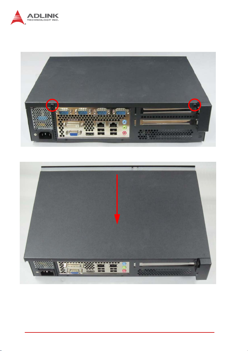
Removing the Chassis Cover
1. Remove the two screws indicated below.
2. Slide the cover back to release the front edge.
10 Getting Started
Page 23

3. Lift off the cover to access the inside of the chassis.
MIX-220
Getting Started 11
Page 24

2.3 Installing the CPU
The MI-220 motherboard supports rPGA988B package Intel®
Core™ and Celeron® processors in Socket G2.
When installing, carefully hold the CPU by its edges and do
not force the CPU into the socket to avoid bending the pins.
WARNING:
To install the CPU:
1. Locate the CPU socket. If the socket is locked, use a
flathead screwdriver to turn the CPU lock screw counterclockwise to the unlocked position.
12 Getting Started
Page 25

2. Align the gold triangle at the upper-right corner of the
CPU with the triangular mark at the upper-right corner of
the socket. Gently place the CPU into the socket. It
should drop into the socket without having to apply any
downward force.
You should not have to press down on the processor. If the
processor does not drop completely into the socket, make
CAUTION:
sure the CPU lock screw is fully turned to the unlocked
position.
MIX-220
3. While gently holding the processor down with your fin-
ger, turn the CPU lock screw clockwise to lock the CPU
in place.
Getting Started 13
Page 26

2.4 Installing the CPU Cooler
2.1 Installing the CPU Cooler
An approved CPU cooler must be installed before using the sys-
An approved CPU cooler must be installed before using the system. Failure to install a CPU cooler may damage the mother-
tem. Failure to install a CPU cooler may damage the motherboard and/or CPU.
CAUTION:
CAUTION:
To install the CPU cooler:
To install the CPU cooler:
CPU Fan
CPU Fan
Connector
Connector
board and/or CPU.
1. The CPU cooler has a layer of thermal grease
1. The CPU cooler has a layer of thermal grease
pre-applied. If you are reinstalling the CPU, apply a new
pre-applied. If you are reinstalling the CPU, apply a new
layer of thermal grease evenly to t he top of the installed
layer of thermal grease evenly to t he top of the installed
CPU.
CPU.
2. Position the heatsink on top of the installed CPU until the
2. Position the heatsink on top of the installed CPU until the
heatsink screws match the screw holes on the board.
heatsink screws match the screw holes on the board.
3. Tighten the heatsink’s spring-loaded screws in a diag o-
3. Tighten the heatsink’s spring-loaded screws in a diag onal sequence until it is securely attached to the board.
nal sequence until it is securely attached to the board.
4. Connect the fan power cable to the CPU fan connector
4. Connect the fan power cable to the CPU fan connector
on the motherboard (CPU_FAN1)
on the motherboard (CPU_FAN1)
14 Getting Started
Page 27

MIX-220
2.5 System Memory
The MI-220 supports up to 8GB of DDR3 1066/1333MHz in two
204-pin SO-DIMM sockets.
Memory Module Installation
The DDR3 memory modules are notched to facilitate correct
installation in the DIMM sockets.
Disconnect all power supply to the board before installing a
memory module to prevent damaging the board and mem-
WARNING:
To install a memory module:
1. Locate the SO-DIMM slots on the motherboard.
2. Align the memory module on the socket, making sure
3. Insert the module firmly into the slot until the retaining clips
ory module.
that the notch matches the break on the socket.
snap back inwards and the module is securely seated.
Getting Started 15
Page 28
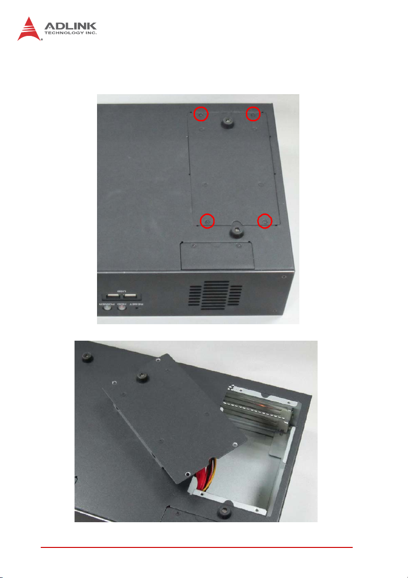
2.6 SATA Drive Installation
1. Remove the four screws securing the drive bracket to
the chassis.
2. Lift the drive bracket out of the chassis.
16 Getting Started
Page 29

3. Remove the four screws securing the two sets of SATA
signal and power cables to the drive bracket.
4. Turn the drive bracket over and locate the mounting
screws and shock absorbers in the accessory kit (four
each per drive).
MIX-220
Getting Started 17
Page 30

5. Carefully insert four shock absorbers for each drive you
wish to install.
6. Place the 2.5” SATA drive in the drive bracket with the
top side up as shown. Check that the connectors on the
drive align with the opening in the bracket. Secure the
drive to the bracket with the mounting screws provided.
SATA
Connectors
7. Repeat steps 5 and 6 if you wish to install a second
drive.
18 Getting Started
Page 31

8. Connect the SATA signal and power cable(s) to the
drive(s) and secure both cables to the bracket with the
four screws removed in step 3.
Be sure to secure both sets of SATA cables to the drive
bracket to prevent them from interfering with cooling fan
CAUTION:
operation. Failure to do so may cause the system to overheat and/or damage components.
9. Place the drive bracket into the chassis and secure it
with the four screws removed in step 1.
MIX-220
Getting Started 19
Page 32
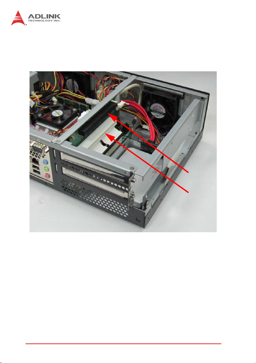
2.7 Installing PCIe/PCI Cards
Remove the chassis cover as described on page 10. The MIX-220
provides one PCIe x16 expansion slot (upper) and one PCI exp ansion slot (lower). The maximum allowed card length is 190 mm.
PCIe x16
PCI
20 Getting Started
Page 33
MIX-220
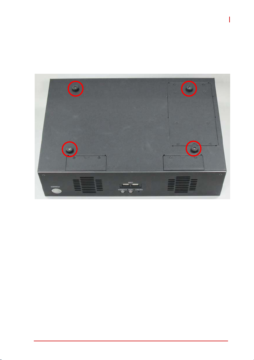
2.8 Wall Mount Brackets
Two wall mount brackets and mounting screws are provided for
the MIX-220. Before installing the brackets, remove the four rubber feet from the bottom of the chassis as indicated below.
The bracket mounting locations are shown in Figure 1-2:
MIX-220 Dimensions (with wall mount brackets) on page 6.
Getting Started 21
Page 34

2.9 Powering Up
Connect the AC power cord to the AC connector on the rear panel
of the chassis. Plug the AC power cord into a suitable wall outlet.
Power on any peripheral devices, such as a display monitor.
Press the On/Off power switch on the front of the chassis to power
on the system.
22 Getting Started
Page 35

MIX-220
2.10 Driver Installation
The MI-220 drivers for Windows XP 32-bit are located in the following directories on the Driver CD, or can be downloaded from
the ADLINK website (http://www.adlinktech.com):
Chipset X:\Driver\Step 1_CHIP\
Display X:\Driver\Step 2_VGA\winxp32
LAN X:\Driver\Step 3_LAN\XP_32
Audio X:\Driver\Step 4_AUDIO\XP 32_64
RAID X:\Driver\Step 5_RAID\
Mgmt. Engine X:\Driver\Step 6_ME\
Follow the instructions below to install the required MI-220 drivers:
1. Install the Windows operating system before installing any
driver. Most standard I/O device drivers are installed during
Windows installation.
In order to enable AHCI mode, you must pre-install the Intel®
Rapid Storage Technology driver using the F6 installation
NOTE:
NOTE:
method described in X:\Driver\Step 5_RAID\F6Readme.txt.
2. Install the Chipset driver by running the program
X:\Driver\Step 1_CHIP\\infinst_autol.exe. Follow the instructions given and reboot when instructed.
3. Install the Display driver and utilities by running the program
X:\Driver\Step 2_VGA\winxp32\winxp_14464.exe. Follow
the instructions given and reboot when instructed.
4. Install the LAN driver by running the program
X:\Driver\Step 3_LAN\XP_32\PROWin32.exe. Follow the
instructions given and reboot if required.
5. Install the Audio driver by running the program
X:\Driver\Step 4_AUDIO\XP 32_64\WDM_R261.exe. Follow
the instructions given and reboot if required.
Getting Started 23
Page 36

6. Install the Intel Rapid Storage Technology Utility by extracting
and running the program iata_cd_10.6.0.1022.exe in
X:\Driver\Step 5_RAID\Intel_Rapid_Storage_Technology_
10.6.0.1022.zip.
The Intel Rapid Storage Technology Utility file may not be
included on the Driver CD. Please download it from the
NOTE:
NOTE:
ADLINK website if necessary.
Install the Management Engine driver by running the program
X:\Driver\Step 6_ME\setup.exe. Follow the instructions given
and reboot if required.
24 Getting Started
Page 37

3 Hardware Information
3.1 Fan Removal and Replacement
1. Remove the two screws securing the fan module to the
chassis.
MIX-220
2. Lift the fan module out of the chassis as shown. Cut and
remove the cable tie to release the wiring.
Hardware Information 25
Page 38

3. Remove the fan module from the chassis. Replace the
fan and/or air filter as required.
4. Use a new cable tie to shorten the wiring and secure it
towards the center of the chassis as shown to prevent
the wiring from interfering with normal fan operation.
Center of
the Chassis
Failure to properly secure the wiring may result in improper
cooling fan operation, causing the system to overheat
CAUTION:
26 Hardware Information
and/or damage to components.
Page 39

5. Insert the fan module into the chassis. Make sure the
module fits into the slots inside the chassis.
6. Place the connector into the gap beside the fan to allow
it to fit into the chassis.
MIX-220
7. Slide the module into the chassis and secure it with the
two screws removed in step 1.
8. Repeat steps 1 through 7 for the other fan module if
required.
Hardware Information 27
Page 40

3.2 I/O Connector Pin Definitions
For detailed information about onboard motherboard connectors
and pin definitions, refer to the MI-220 User’s Manual.
VGA Connector.
Signal Name Pin # Pin # Signal Name
Red 1 2 Green
Blue 3 4 VCC pull-up
GND 5 6 GND
GND 7 8 GND
VCC 9 10 GND
VCC pull-up 11 12 DDC2B DATA
HSYNC 13 14 VSYNC
DDC2B CLK 15
HDMI Connector
Pin # Signal Pin # Signal
1 TMDS Data2+ 2 TMDS Data2 Shield
3 TMDS Data2– 4 TMDS Data1+
5 TMDS Data1 Shield 6 TMDS Data1–
7 TMDS Data0+ 8 TMDS Data0 Shield
9 TMDS Data0– 10 TMDS Clock+
11 TMDS Clock Shield 12 TMDS Clock–
13 CEC 14 Reserved
15 SCL 16 SDA
17 DDC/CEC Ground 18 +5 V Power
19 Hot Plug Detect
28 Hardware Information
Page 41

DVI-D Connector
Pin # Signal Pin # Signal
1 TMDS Data2- 16 Hot Plug Detect
2 TMDS Data2+ 17 TMDS Data03 TMDS Data2/4 Shield 18 TMDS Data0+
4 TMDS Data4- 19 TMDS Data0/5 Shield
5 TMDS Data4+ 20 TMDS Data56 DDC Clock 21 TMDS Data5+
7 DDC Data 22 TMDS Clock Shield
8 Analog Vertical Sync 23 TMDS Clock +
9 TMDS Data1- 24 TMDS Clock 10 TMDS Data1+ C1 NC
11 TMDS Data1/3 Shield C2 NC
12 TMDS Data3- C3 NC
13 TMDS Data3+ C4 NC
14 +5 V Power C5 NC
15 GND
MIX-220
Although the connector has a DVI-I type pinout, pins C1
through C5 are not connected and VGA signals are NOT
NOTE:
NOTE:
supported.
USB Connectors
Pin # Signal Name
1Vcc
2 USB3 USB+
4GND
Hardware Information 29
Page 42
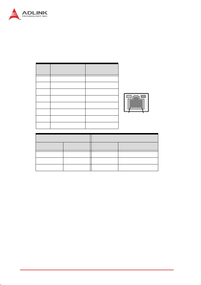
LAN Port (RJ-45)
This port allows gigabit connection to a Local Area Network (LAN)
using a network hub. The LAN port comes with two LEDs to indicate link, activity and speed. Refer to the tables below for the LAN
port pin and LED definitions.
Pin #
1 TX+ BI_DA+
2 TX- BI_DA3 RX+ BI_DB+
4-- BI_DC+
5 -- BI_DC6 RX- BI_DB7-- BI_DD+
8 -- BI_DD-
LED1 (Activity/Link) LED2 (Speed)
Status Description Status Description
Orange Linked Orange 100 Mb connection
Blinking Data Activity Green 1 Gb connection
10BASE-
T/100BASE-TX
Off No Link Off 10 Mb connection
1000BASE-T
LED1
LED2
18
Audio Ports
The three-jack audio I/O supports Line-In, Line-Out, and Mic-In
functions. The blue Line-In jack connects to an audio source such
as a CD player. The green Line-Out port connects to speakers or
headphones, while the pink Mic-In jack connects to a microphone.
30 Hardware Information
Page 43

COM1 Connector (DB-9)
Pin # RS-232 RS-422 RS-485
1 DCD-L TXD- TXD2RXDTXD+TXD+
3TXDRXD+ —
4 DTR-L RXD- —
5 GND GND GND
6DSR-L — —
7RTS-L — —
8CTS-L — —
9RI-L — —
See the MI-220 User’s Manual BIOS chapter for COM1 Serial
Port Mode settings.
NOTE:
NOTE:
COM2~4 Connector (DB-9)
Pin # RS-232
1DCD-L
2RXD
3TXD
4DTR-L
5GND
6DSR-L
7RTS-L
8CTS-L
9RI-L
MIX-220
6
6
1
5
1
5
Hardware Information 31
Page 44

This page intentionally left blank.
32 Hardware Information
Page 45

XMC-E540
Important Safety Instructions
For user safety, please read and follow all instructions,
WARNINGS, CAUTIONS, and NOTES marked in this manual
and on the associated equipment before handling/operating the
equipment.
X Read these safety instructions carefully.
X Keep this user’s manual for future reference.
X Read the specifications section of this manual for detailed
information on the operating environment of this equipment.
X When installing/mounting or uninstalling/removing
equipment:
Z Turn off power and u nplug any power cords/cables.
X To avoid electrical shock and/or damage to equipment:
Z Keep equipment away from water or liquid sources;
Z Keep equipment away from high heat or high humidity;
Z Keep equipment properly ventilated (do not block or
cover ventilation openings);
Z Make sure to use recommended voltage and powe r
source settings;
Z Always install and operate equipment near an easily
accessible electrical socket-outlet;
Z Secure the power cord (do not place any obje ct on /ove r
the power cord);
Z Only install/attach and operate equipment on stable
surfaces and/or recommended mountings; and,
Z If the equipment will not be used for long periods of time,
turn off and unplug the equipment from its power source.
Important Safety Instructions 33
Page 46

X Never attempt to fix the equipment. Equipmen t sho u ld on ly
be serviced by qualified personnel.
A Lithium-type battery may be provided for uninterrupted, backup
or emergency power.
Risk of explosion if battery is replaced with one of an incorrect
WARNING:
type. Dispose of used batteries appropriately.
X Equipment must be serviced by authorized technicians
when:
Z The power cord or plug is damaged;
Z Liquid has penetrated the equipment;
Z It has been exposed to high humidity/moisture;
Z It is not functioning or does not function according to the
user’s manual;
Z It has been dropped and/or damaged; and/or,
Z It has an obvious sign of breakage.
34 Important Safety Instructions
Page 47

Getting Service
Contact us should you require any service or assistance.
ADLINK Technology, Inc.
Address: 9F, No.166 Jian Yi Road, Zhonghe District
New Taipei City 235, Taiwan
ᄅקؑխࡉ৬ԫሁ 166 ᇆ 9 ᑔ
Tel: +886-2-8226-5877
Fax: +886-2-8226-5717
Email: service@adlinktech.com
Ampro ADLINK Technology, Inc.
Address: 5215 Hellyer Avenue, #110, San Jose, CA 95138, USA
Tel: +1-408-360-0200
Toll Free: +1-800-966-5200 (USA only)
Fax: +1-408-360-0222
Email: info@adlinktech.com
ADLINK Technology (China) Co., Ltd.
Address: Ϟ⍋Ꮦ⌺ϰᮄᓴ∳催⾥ᡔು㢇䏃 300 ো(201203)
300 Fang Chun Rd., Zhangjiang Hi-Tech Park,
Pudong New Area, Shanghai, 201203 China
Tel: +86-21-5132-8988
Fax: +86-21-5132-3588
Email: market@adlinktech.com
MIX-220
ADLINK Technology Beijing
Address: ࣫ҀᏖ⍋⎔Ϟഄϰ䏃 1 োⲜ߯ࡼ E ᑻ 801 ᅸ(100085)
Tel: +86-10-5885-8666
Fax: +86-10-5885-8626
Email: market@adlinktech.com
ADLINK Technology Shenzhen
Address: ⏅ഇᏖቅ⾥ᡔು催ᮄϗ䘧᭄ᄫᡔᴃು
Tel: +86-755-2643-4858
Fax: +86-755-2664-6353
Email: market@adlinktech.com
LiPPERT ADLINK Technology GmbH
Address: Hans-Thoma-Strasse 11, D-68163, Mannheim, Germany
Tel: +49-621-43214-0
Fax: +49-621 43214-30
Email: emea@adlinktech.com
Rm. 801, Power Creative E, No. 1, B/D
Shang Di East Rd., Beijing, 100085 China
A1 2 ὐ C (518057)
2F, C Block, Bldg. A1, Cyber-Tech Zone, Gao Xin Ave. Sec. 7,
High-Tech Industrial Park S., Shenzhen, 518054 China
Getting Service 35
Page 48

ADLINK Technology, Inc. (French Liaison Office)
Address: 15 rue Emile Baudot, 91300 Massy CEDEX, France
Tel: +33 (0) 1 60 12 35 66
Fax: +33 (0) 1 60 12 35 66
Email: france@adlinktech.com
ADLINK Technology Japan Corporation
Address: ͱ101-0045 ᵅҀ䛑ҷ⬄⼲⬄䤯ފ⬎ 3-7-4
Tel: +81-3-4455-3722
Fax: +81-3-5209-6013
Email: japan@adlinktech.com
ADLINK Technology, Inc. (Korean Liaison Office)
Address: 昢殾柢 昢爎割 昢爎壟 1675-12 微汾瘶捒娯 8猻
Tel: +82-2-2057-0565
Fax: +82-2-2057-0563
Email: korea@adlinktech.com
ADLINK Technology Singapore Pte. Ltd.
Address: 84 Genting Lane #07-02A, Cityneon Design Centre,
Tel: +65-6844-2261
Fax: +65-6844-2263
Email: singapore@adlinktech.com
ADLINK Technology Singapore Pte. Ltd. (Indian Liaison Office)
Address: 1st Floor, #50-56 (Between 16th/17th Cross) Margosa Plaza,
Tel: +91-80-65605817, +91-80-42246107
Fax: +91-80-23464606
Email: india@adlinktech.com
⼲⬄ 374 ɛɳ 4F
KANDA374 Bldg. 4F, 3-7-4 Kanda Kajicho,
Chiyoda-ku, Tokyo 101-0045, Japan
8F Mointer B/D,1675-12, Seocho-Dong, Seocho-Gu,
Seoul 137-070, Korea
Singapore 349584
Margosa Main Road, Malleswaram, Bangalore-560055, India
ADLINK Technology, Inc. (Israeli Liaison Office)
Address: 6 Hasadna St., Kfar Saba 44424, Israel
Tel: +972-9-7446541
Fax: +972-9-7446542
Email: israel@adlinktech.com
36 Getting Service
 Loading...