

Page 1
MIX-110
Embedded Computer System
User’s Manual
Manual Rev.: 2.00
Revision Date: January 13, 2014
Part No: 50-1Z147-1000
Advance Technologies; Automate the World.
Page 2

Revision History
Revision Release Date Description of Change(s)
2.00 2014/1/13
Initial release
ii Revision History
Page 3

MIX-110
Preface
Copyright 2014 ADLINK Technology Inc.
This document contains proprietary infor mation protected by copyright. All rights are reserved. No part of this manual may be reproduced by any mechanical, electronic, or other means in any form
without prior written permission of the manufacturer.
Disclaimer
The information in this document is subject to change without prior
notice in order to improve reliability, design, and function and does
not represent a commitment on the part of the manufa cturer.
In no event will the manufacturer be liable for direct, indirect, special, incidental, or consequential damages arising out of the use or
inability to use the product or documentation, even if advised of
the possibility of such damages.
Environmental Responsibility
ADLINK is committed to fulfill its social responsibility to global
environmental preservation through compliance with the European Union's riction of Hazardous Substances (RoHS) directive
and Waste Electrical and Electronic Equipment (WEEE) directive.
Environmental protection is a top priority for ADLINK. We have
enforced measures to ensure that our products, manufacturing
processes, components, and raw materials have as little impact on
the environment as possible. When products are at their end of
life, our customers are encouraged to dispose of them in accordance with the product disposal and/or recovery programs prescribed by their nation or company.
Trademarks
Product names mentioned herein are used for identification purposes only and may be trademarks and/or registered trademarks
of their respective companies.
Preface iii
Page 4

Using this Manual
Audience and Scope
The MIX-110 User’s Manual is intended for hardware technicians
and systems operators with knowledge of installing, configuring
and operating embedded single board computers.
Manual Organization
This manual is organized as follows:
Preface: Presents copyright notifications, disclaimers, trade-
marks, and associated information on the proper usage of this
document and its associated product(s).
Chapter 1, Introduction: Introduces the MIX-110, its features,
specifications and mechanical dimensions.
Chapter 2, Getting Started: Presents information on chassis layout, setup and operation of the MIX-110.
Chapter 3, Hardware Information: Provides
connectors and pin assignments
.
information about
Important Safety Instructions: Presents safety instructions all
users must follow for the proper setup, installation and usage of
equipment and/or software.
Getting Service: Contact information for ADLINK’s worldwide
offices.
iv Preface
Page 5
MIX-110
Conventions
Take note of the following conventions used throughout this
manual to make sure that users perform certain tasks and
instructions properly.
Additional information, aids, and tips that help users perform
tasks.
NOTE:
NOTE:
Information to prevent minor physical injury, component damage, data loss, and/or program corruption when trying to com-
CAUTION:
WARNING:
plete a task.
Information to prevent serious physical injury, component
damage, data loss, and/or program corruption when trying to
complete a specific task.
Preface v
Page 6

This page intentionally left blank.
vi Preface
Page 7

MIX-110
Table of Contents
Revision History...................................................................... ii
Preface.................................................................................... iii
List of Figures........................................................................ ix
List of Tables.......................................................................... xi
1 Introduction ........................................................................ 1
1.1 Overview.............................................................................. 1
1.2 Features............................................................................... 1
1.3 Specifications....................................................................... 2
1.4 Mechanical Drawing ............................................................ 4
2 Getting Started ................................................................... 7
2.1 Packing List ......................................................................... 7
2.2 Chassis Layout .................................................................... 8
2.3 SATA Drive Removal........................... ... ... ... ... .... ... ... ... .... . 11
2.4 System Memory................................................................. 14
2.5 Powering Up...................................................................... 16
2.6 Driver Installation................................................. ... ... ... .... . 17
2.7 Wall-mount Bracket ........................................................... 18
3 Hardware Information...................................................... 21
3.1 Rear I/O Layout ................................................................. 21
3.2 Rear I/O Connector Pin Definitions.................................... 22
3.3 Board Layout ..................................................................... 26
3.4 Onboard Connector Pin Definitions ................................... 28
Important Safety Instructions.............................................. 37
Getting Service...................................................................... 39
Table of Contents vii
Page 8

This page intentionally left blank.
viii Table of Contents
Page 9

MIX-110
List of Figures
Figure 1-1: MIX-110 Dimensions (w/o wall-mount bracket) .... ... .... ... . 4
Figure 1-2: MIX-110 Dimensions (w/ wall-mount bracket).................5
Figure 2-1: MIX-110 Front/Rear Panel...............................................8
Figure 3-1: IMB-T10 Rear I/O Layout............................................... 21
Figure 3-2: IMB-T10 Board Layout................................................... 26
List of Figures ix
Page 10

This page intentionally left blank.
xList of Figures
Page 11

MIX-110
List of Tables
Table 1-1: MIX-110 General Specifications......................................3
Table 3-1: Board Layout Legend .................................................... 27
List of Tables xi
Page 12

This page intentionally left blank.
xii List of Tables
Page 13

1 Introduction
This chapter will introduce the MIX-110, its features, specifications, and mechanical layout. For detailed information on the
IMB-T10 Mini-ITX industrial motherboard, refer to the user manual
downloadable from the ADLINK website:
http://www.adlinktech.com/PD/web/PD_detail.php?pid=1251
1.1 Overview
The MIX-110 is an embedded computer system based on the
IMB-T10 Mini-ITX form factor industrial motherboard supporting
onboard Intel® Atom™ Processor D2550, Intel® NM10 Express
Chipset and single channel DDR3 1066/800MHz memory (up to
4GB) in one SODIMM slot. Features include integrated Intel®
GMA HD 3650 (VGA, HDMI outputs), dual Gigabit Ethernet, six
USB 2.0 ports, and an externally accessible anti-shock drive bay
for two 2.5" SATA 3Gb/s drives. The MIX-110 provides a PCI
Express Mini Card slot for Wi-Fi module or 3G module (on-board
USIM socket).
1.2 Features
X Embedded computer system (234.4 x 56.6 x 191.2mm)
X Onboard Intel® Atom™ Processor D2550 (1.86GHz)
X Integrated Intel® GMA 3650 with VGA, HDMI outputs
X 2x Realtek RTL8111E Gigabit Ethernet
X 6x USB 2.0 ports (2x front, 4x rear)
X Anti-shock drive bay for two 2.5" SATA 3Gb/s drives
X Two COM Ports (1x RS-232, 1x RS-232/422/485)
X Realtek ALC887 supports Line-out, Mic-in
X RoHS compliant
MIX-110
Introduction 1
Page 14
1.3 Specifications
System
CPU • Intel® Atom™ processor D2550, 1.86GHz, 1024KB L2
cache, µFCBGA1 1
Chipset • Intel® NM10 Express Chipset
Memory • 1x 204-pin SODIMM sockets support up to 4GB single
channel DDR3 800/1066MHz SDRAM
BIOS • AMI UEFI BIOS16Mb SPI flash ROM
Graphics • Integrated Intel® GMA 3650 graphics core
Ethernet • 2x Realtek RTL8111E Gigabit Ethernet
Graphics • Intel® Graphics Media Accelerator 3650 integrated in
CPU supporting dual independent display
• HDMI (version 1.3a) resolution up to 1920x1200@60Hz
• VGA resolution up to 1920x1200@60Hz
Audio • Realtek ALC887 HD Audio
• Line-out and mic-in
Watchdog Timer • 1-255 second/minute programmable
Hardware Monitor • CPU/System temperature, fan speed and onboard DC
voltage
Operating System • Microsoft® Windows® 7 32-bit
• Fedora™ 19
I/O Interfaces
Front I/O • 2x USB 2.0 ports
Rear I/O • 2x RJ-45 LAN ports
• 4x USB 2.0 ports
• 1x RS-232, 1xRS-232/422/485 serial ports
• 1x VGA connector
• 1x HDMI connector
• 1x screw type DC jack
• 2x audio jacks (line-out, mic-in)
Expansion Slots • 1x PCIe Mini Card (USB2.0/mSATA 3Gb/s)
•1x PCI slot
• 1x PCI Express x1 slot compliant with PCI Express Base
1.0a (flying cable solution only due to space limitation)
• SIM card connector (8P, 2.54mm)
LEDs/Switches • Power, HDD (drive activity)
• On/Off button
• Reset button (recessed)
2Introduction
Page 15

Power Requirements
Input • 1x screw-type DC jack (+12V DC in)
• 12V DC power adapter
Mechanical and Environment
Dimensions • 330 mm x 212 mm x 88 mm (W x D x H)
Operating Temp. • 0°C to 40°C
Storage Temp. •-10ºC to 55ºC
Rel. Humidity • 10% to 90%, non-condensing
Certifications • CE, FCC Class A
Table 1-1: MIX-110 General Specifications
MIX-110
Introduction 3
Page 16
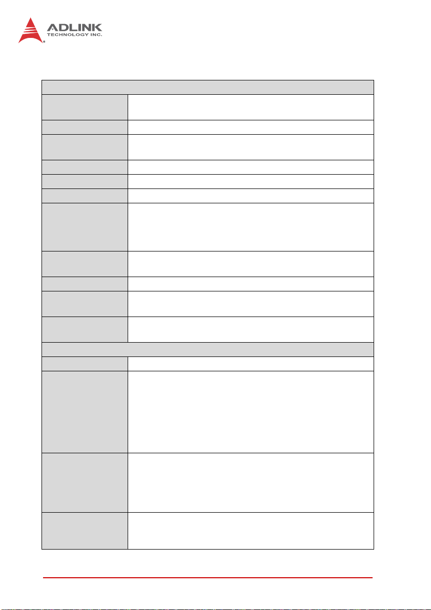
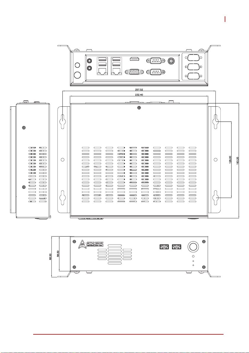
1.4 Mechanical Drawing
Dimensions in mm
Figure 1-1: MIX-110 Dimensions (w/o wall-mount bracket)
4Introduction
Page 17
MIX-110
Dimensions in mm
Figure 1-2: MIX-110 Dimensions (w/ wall-mount bracket)
Introduction 5
Page 18

This page intentionally left blank.
6Introduction
Page 19

2 Getting Started
The following chapter describes how to set up the MIX-110.
2.1 Packing List
Unpack the contents of the shipping carton. Please check that
your package contains the items below. If you discover damaged
or missing items, please contact your vendor.
Z MIX-110 Embedded Computer System
Z Accessory kit: DC adapter, AC power cord (US)
Z Driver CD
Z Wall-mount bracket (optional)
DO NOT install or apply power to equipment that is damaged
or if there is missing/incomplete equipment. Retain the ship-
WARNING:
ping carton and packing materials for inspection. Please contact your ADLINK dealer/vendor immediately for assistance.
Obtain authorization from your dealer before returning any
product to ADLINK.
MIX-110
To prevent damage to the system, ensure there is sufficient
clearance around the air vents for unrestricted airflow. The air
CAUTION:
Getting Started 7
temperature inside the enclosure could rise above the specified operating temperature limits if the airflow through the vents
is restricted.
Page 20
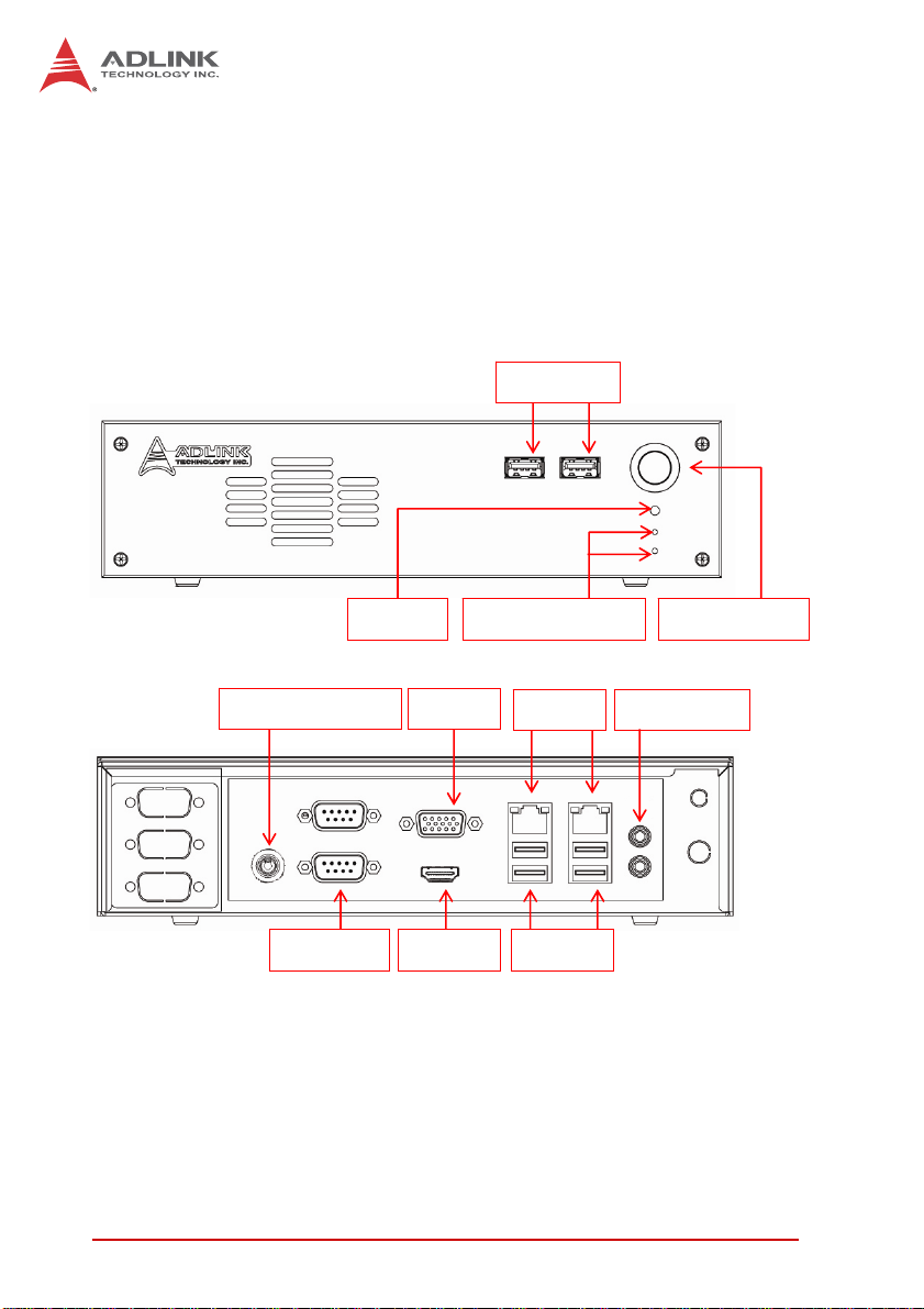
2.2 Chassis Layout
Front and Rear Panels
Connect the desired peripheral devices (e.g. monitor, keyboard, mouse, LAN) to the system. Refer to Figure 2-1 below
for connector locations.
Front Panel
Rear Panel
USB 2.0
Power SwitchPower/HDD LEDsReset
VGADC 12V connector
USB 2.0HDMICOM 1/2
Audio Jack LAN
Figure 2-1: MIX-110 Front/Rear Panel
8 Getting Started
Page 21
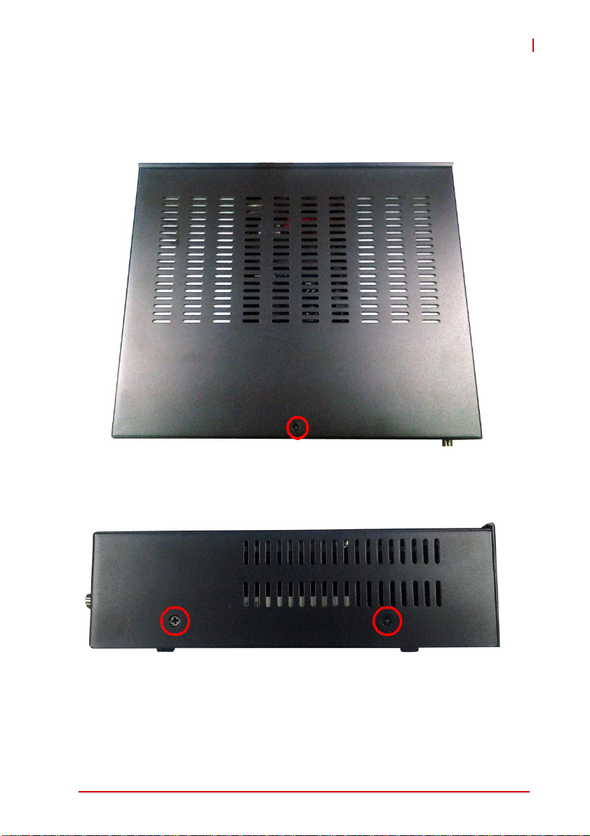
Removing the Chassis Cover
1. 1.Remove one screw at the top rear of the chassis and
two screws on both the left & right sides.
MIX-110
Getting Started 9
Page 22

2. Slide the cover back to release the front edge.
3. Lift off the cover to access the inside of the chassis.
10 Getting Started
Page 23

2.3 SATA Drive Removal
1. 1.Re move one screw on drive bracket.
2. Lift up the drive bracket and pull it out of the chassis.
MIX-110
2: Pull it out of the chassis
1: Lift up the drive bracket
Getting Started 11
Page 24

3. The two SATA drives are connected to the SATA connectors on the motherboard as shown.
SATA SATA
4. The SATA drive is secured by 4 screws on both sides.
Screw
Screw
Screw
Screw
12 Getting Started
Page 25

5. 5.When replacing the SATA drive, be sure to place it in
the drive bracket with the top side up as shown and that
the connectors on the drive are facing away from the
screw hole in the bracket.
Screw hole
SATA connector
MIX-110
Getting Started 13
Page 26

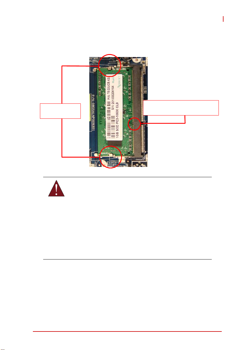
2.4 System Memory
The MIX-110 supports up to 4GB single channel DDR3
1066/800MHz SDRAM in two 204-pin SO-DIMM sockets.
Memory Module Installation
The DDR3 memory modules are notched to facilitate correct
installation in the DIMM sockets.
Disconnect all power supply to the board before installing a
memory module to prevent damaging the board and mem-
WARNING:
To install a memory module:
1. Remove both SATA drive brackets as described above
2. Locate the SO-DIMM slots on the motherboard.
3. Align the memory module on the socket, making sure
ory module.
in “SATA Drive Removal” on page 11.
that the notch matches the break on the socket.
Retaining clip
DDR3 DIMM notch
14 Getting Started
Page 27
MIX-110
4. Insert the module firmly into the slot until the retaining clips
snap back inwards and the module is securely seated.
Retaining
WARNING:
DDR3 SODIM M notch
A DDR3 SO-DIMM is keyed with a notch so that it fits in
only one direction. DO NOT force a SO-DIMM into a
socket to avoid damaging the SO-DIMM.
The DDR3 SODIMM sockets do not support DDR2
SO-DIMMs. DO NOT install DDR2 SODIMMs to the DDR3
SO-DIMM socket.
Make sure to unplug the power supply before adding or
removing DIMMs or other system components. Failure to
do so may cause severe damage to both the motherboard
and the components.
Getting Started 15
Page 28

2.5 Powering Up
Connect the DC adapter with the power cable prov ided to the re ar
panel of the chassis. Power on any peripheral devices, such as a
display monitor.
Press the On/Off power switch on the front of the chassis to power
on the system.
16 Getting Started
Page 29

MIX-110
2.6 Driver Installation
The IMB-T10 drivers for Windows 7 32-bit are located in the following files that can be downloaded from the ADLINK website
(http://www.adlinktech.com):
Chipset \1.Chipset\Intel\(v9.2.2.1034)\
Display \2.VGA\Win7_32\(v8.0.0.6.1082)\
Audio \3.Audio\6937_PG367_Win8_Win7_Vista_XP_WHQLed\
LAN \4.LAN\WIN7\Install_Win7_7069_03212013\
COM \5.COM\
Follow the instructions below to install the required IMB-T10 drivers:
1. Install the Windows operating system before installing any
driver. Most standard I/O device drivers are installed during
Windows installation.
2. Install the Chipset driver by running the program \1.Chip-
set\Intel\(v9.2.2.1034)\setup.exe. Follow the instructions
given and reboot when instructed.
3. Install the Display driver and utilities by running the program
\2.VGA\Win7_32\(v8.0.0.6.1082)\setup.exe. Follow the
instructions given and reboot when ins tru ct ed .
4. Install the Audio driver by running the program \3.Audio\
6937_PG367_Win8_Win7_Vista_XP_WHQLed\setup.exe.
Follow the instructions given and reboot if required.
5. Install the LAN driver by running the program \4.LAN\
WIN7\Install_Win7_7069_03212013\LAN\Win7\setup.exe.
Follow the instructions given and reboot if required.
6. Install the COM driver by running the program
\5.COM\NuvSerial v1.0.2011.1109 (WHQL).exe. Follow the instructions given and reboot if required.
Getting Started 17
Page 30

2.7 Wall-mount Bracket
An optional wall-mount bracket is available for the MIX-110. Contact your ADLINK representative for ordering information.
Install the brackets onto the chassis using the four screws provided as shown below.
4x wall-mount
bracket screw
18 Getting Started
Page 31
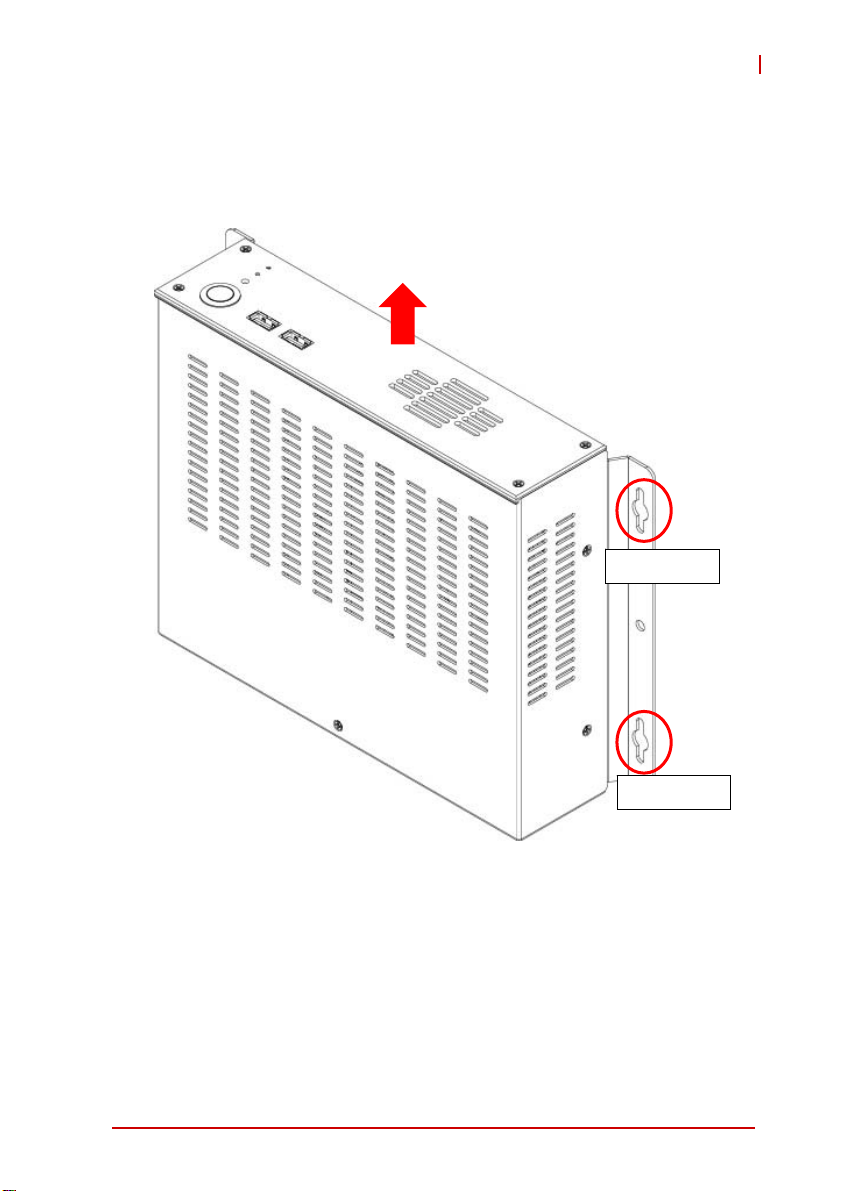
MIX-110
Attach the MIX-110 to the wall as required using th e screw holes in
the wall-mount brackets. Refer to Figure 1-2: MIX-110 Dimensions
(w/ wall-mount bracket) on page 5 for mounting hole dimensions.
Top Side
Screw holes
Screw holes
Getting Started 19
Page 32

This page intentionally left blank.
20 Getting Started
Page 33

3 Hardware Information
3.1 Rear I/O Layout
MIX-110
1
2
3
11
10
Figure 3-1: IMB-T10 Rear I/O Layout
1 COM port (COM2)
2 VGA port
3 LAN RJ-45 port
4 LAN RJ-45 port
5 Line-out (green)
6 Mic-in (pink)
7 USB 2.0 Ports (USB23)
8 USB 2.0 Ports (USB01)
9 HDMI port
10 COM port (COM1)
11 DC jack
9
8
4
5
6
7
Hardware Information 21
Page 34

3.2 Rear I/O Connector Pin Definitions
VGA Connector.
Signal Name Pin # Pin # Signal Name
Red 1 2 Green
Blue 3 4 VCC pull-up
GND 5 6 GND
GND 7 8 GND
VCC 9 10 GND
VCC pull-up 1 1 12 DDC2B DATA
HSYNC 13 14 VSYNC
DDC2B CLK 15
USB Connectors
Pin # Signal Name
1Vcc
2 USB3 USB+
4GND
22 Hardware Information
Page 35

MIX-110
LAN Port (RJ-45)
This port allows gigabit connection to a Local Area Network (LAN)
using a network hub. The LAN port comes with two LEDs to indicate link, activity and speed. Refer to th e tables b e low f or th e L AN
port pin and LED definitions.
Pin #
1 TX+ BI_DA+
2 TX- BI_DA3 RX+ BI_DB+
4 -- BI_DC+
5-- BI_DC6 RX- BI_DB7 -- BI_DD+
8-- BI_DD-
LED1 (Activity/Link) LED2 (Speed)
Status Description Status Description
Orange Linked Orange 100 Mb connection
Blinking Data Activity Green 1 Gb connection
10BASE-
T/100BASE-TX
Off No Link Off 10 Mb connection
1000BASE-T
LED1
LED2
18
Hardware Information 23
Page 36

COM1/2 Connectors (DB-9)
Pin # RS-232 RS-422* RS-485*
1 DCD-L TX- RTX2RXD TX+ RTX+
3TXD RX+ N/A
4DTR-L RX- N/A
5GND
6DSR-L N/A
7RTS-L N/A
8CTS-L N/A
9RI-L N/A
*RS-422/485 signals supported on COM1 only. See COM1
Mode jumper settings below and 3.3 Board Layout on p. 26 for
NOTE:
NOTE:
J3 location.
COM1 RS-232/422/485 Mode Select (J3)
Pins RS-232 RS-422 RS-485
1-2 Open Shorted Shorted
3-4 Open Shorted Open
5-6 Open Open Shorted
6
1
5
24 Hardware Information
Page 37

MIX-110
HDMI Connector
Pin # Signal Pin # Signal
1 TMDS Data2+ 2 TMDS Data2 Shield
3 TMDS Data2– 4 TMDS Data1+
5 TMDS Data1 Shield 6 TMDS Data1–
7 TMDS Data0+ 8 TMDS Data0 Shield
9 TMDS Data0– 10 TMDS Clock+
11 TMDS Clock Shield 12 TMDS Clock–
13 CEC 14 Reserved
15 SCL 16 SDA
17 DDC/CEC Ground 18 +5 V Powe r
19 Hot Plug Detect
Audio Ports
The two-jack audio I/O supports Line-out, and Mic-in functions.
The green Line-out port connects to speakers or headphones,
while the pink Mic-in jack connects to a microphone.
Hardware Information 25
Page 38

3.3 Board Layout
31
30
DC_JACK1
COM1
HDMI1
USB 2.0
T: USB 0
B: USB 1
USB 2.0
T: USB 2
B: USB 3
MI
toB
i
cn
t
o
m
:
S
aep
tnorF
ek
r
AT X 12 V 1
COM2
1
1
VGA1
RJ-45
RJ-45
T:
o
p
1
1
PWR_COM2
PWR_COM1
HD_AUDIO1
1
PANEL1
PLED PWRBT N
HDLED RESET
56
LAN_LED2
1
1
LAN_LED1
AT
AS-inim
1
2
34
KB_MS1
1
J3
SIM1
ICP-i
n
i/e
m
yr
SOMC
e
tta
B
AUDI O
CODE C
S uper
I/O
1
PCI1
8
7
USB6_7
1
1
BLT_PWM1
1
BLT_PWM2
PNL_PWR1
1
PNL_PWR2
10 11 12 13
9
BLT_VOL1
INVERTER1
INVERTER2
1
1
1
CPU_F AN1
USB4_5
1
14
LV DS 2
LV DS 1
SATA_PWR 1 SATA_PWR 2
_
2A
A
ST 2
BIOS
Chip
CHA_F AN1
DDR3_A1
1
_2
A
SAT
15
16
17
18
19
20
21
22
6
CI2
1
BUZZ1
TPM1
DGIO1
1
1
1
1
1
CI1
MSATA_SEL 1
PWR_JP 1
CLRCMOS 1
1
_
_
7MOC0
3
MO
C
11
PCIE1
2729
26
2528
23
24
Figure 3-2: IMB-T10 Board Layout
26 Hardware Information
Page 39

1 ATX 12V Power Connector (Input/Output 10A)
2 COM1 Mode Jumper (J3)
3 Keyboard/Mouse Connector
4 System Panel Header
5 LAN Active LED Header (LAN LED1)
6 LAN Active LED Header (LAN LED2)
7 USB 2.0 Header (USB6_7)
8 BLT_PWM1 & BLT_PWM2, PNL_PWR1 & PNL_PWR2
9 Inverter Connector (Inverter1)
10 Inverter Connector (Inverter2)
11 Backlight Volume Control
12 4-Pin CPU F an Connector (+12V)
13 USB 2.0 Header (USB4_5)
14 LVDS Panel Connector (LVDS1)
15 LVDS Panel Connector (LVDS2)
16 SATA Power Output Connector (SATA_PWR1)
17 SATA Power Output Connector (SATA_PWR2)
18 COM Connector (COM7_10)
19 COM Connector (COM3_6)
20 SATA Connector (SATA2_1)
21 SATA Connector (SATA2_2)
22 4-Pin Chassis Fan Connector (+12V)
23 MSATA_SEL1 Jumper
24 PWR_JP1 Jumper
25 Clear CMOS Header
26 Chassis Intrusion Headers (CI1, CI2)
27 DGIO1 Header
28 TPM Header
29 Front Panel Audio Header
30 PWR_COM Jumper (PWR_COM1)
31 PWR_COM Jumper (PWR_COM2)
MIX-110
Table 3-1: Board Layout Legend
Hardware Information 27
Page 40

3.4 Onboard Connector Pin Definitions
LVDS Panel Connector (LVDS1/2)
Pin # Signal Pin # Signal
1 VDD_PWR1 2 +5V
3 VDD_PWR1 4 +5V
5 LBKLT_EN1 6 LBKLT_CTL1
7 GND 8 GND
9 DPLVD_A_DATA1 10 DPLVD_A_DATA0
11 DPLVD_A_DATA1# 12 DPLVD_A_DATA0#
13 GND 14 GND
15 DPLVD_A_DATA3 16 DPLVD_A_DATA2
17 DPLVD_A_DATA3# 18 DPLVD_A_DATA2#
19 GND 20 GND
21 DPLVD_B_DATA1 22 DPLVD_B_DATA0
23 DPLVD_B_DATA1# 24 DPLVD_B_DATA0#
25 GND 26 GND
27 DPLVD_B_DATA3 28 DPLVD_B_DATA2
29 DPLVD_B_DATA3# 30 DPLVD_B_DATA2#
31 GND 32 GND
33 DPLVD_B_CLK 34 DPLVD_A_CLK
35 DPLVD_B_CLK# 36 DPLVD_A_CLK#
37 GND 38 GND
39 +12V 40 +12V
28 Hardware Information
Page 41
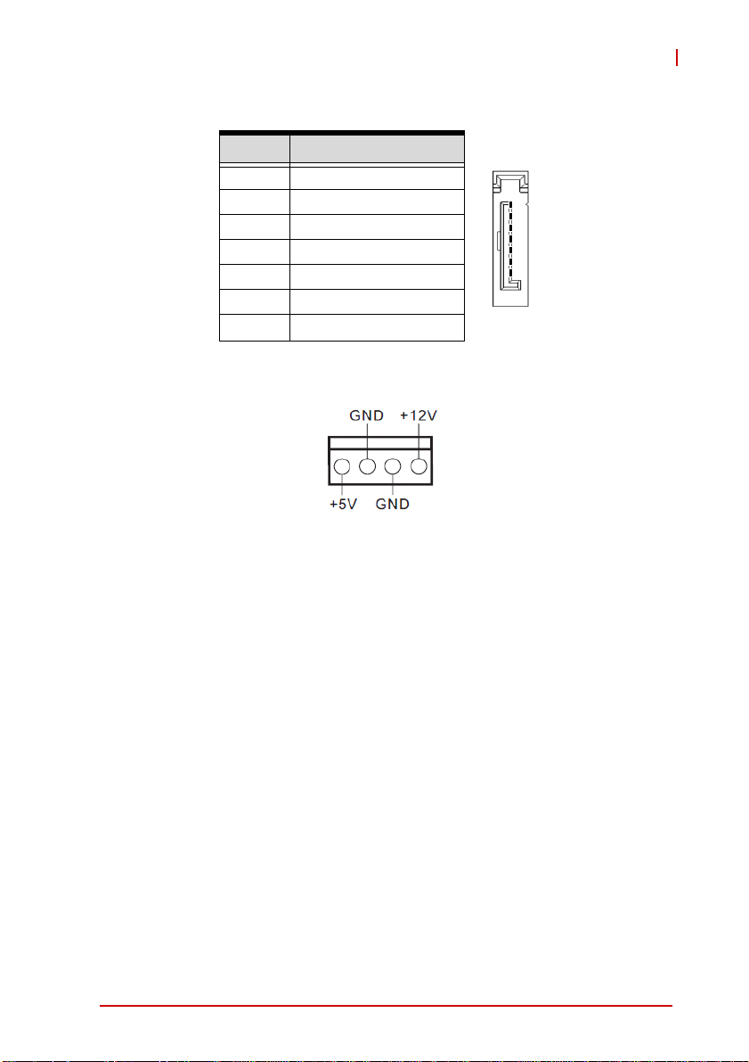
SATA Signal Connectors (SATA2_1/2)
Pin # Signal
1 GND
2 TXP
1
3 TXN
4 GND
5 RXN
7
6 RXP
7 GND
SATA Power Output Connectors (SATA_PWR1/2)
MIX-110
Hardware Information 29
Page 42

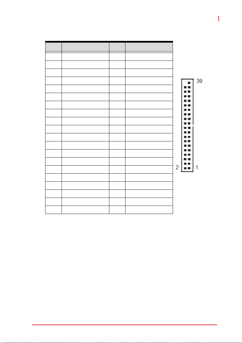
COM3~6 Connector (COM3_6)
Pin # Signal Pin # Signal
1 DDCD#_3 2 DDSR#_3
3 RRXD_3 4 RRTS#_3
5 TTXD_3 6 CCTS#_3
7 DDTR#_3 8 RRI#3
9GND10 X
11 DDCD#_4 12 DDSR#_4
13 RRXD_4 14 RRTS#_4
15 TTXD_4 16 CCTS#_4
17 DDTR#_4 18 RRI#4
19 GND 20 X
21 DDCD#_5 22 DDSR#_5
23 RRXD_5 24 RRTS#_5
25 TTXD_5 26 CCTS#_5
27 DDTR#_5 28 RRI#5
29 GND 30 X
31 DDCD#_6 32 DDSR#_6
33 RRXD_6 34 RRTS#_6
35 TTXD_6 36 CCTS#_6
37 DDTR#_6 38 RRI#6
39 GND
30 Hardware Information
Page 43
COM7~10 Connector (COM7_10)
Pin # Signal Pin # Signal
1 DDCD#_A 2 DDSR#_A
3 RRXD_A 4 RRTS#_A
5 TTXD_A 6 CCTS#_A
7 DDTR#_A 8 RRIXA
9GND10 X
11 DDCD#_B 12 DDSR#_B
13 RRXD_B 14 RRTS#_B
15 TTXD_B 16 CCTS#_B
17 DDTR#_B 18 RRI#B
19 GND 20 X
21 DDCD#_C 22 DDSR#_C
23 RRXD_C 24 RRTS#_C
25 TTXD_C 26 CCTS#_C
27 DDTR#_C 28 RRI#C
29 GND 30 X
31 DDCD#_D 32 DDSR#_D
33 RRXD_D 34 RRTS#_D
35 TTXD_D 36 CCTS#_D
37 DDTR#_D 38 RRI#D
39 GND
MIX-110
Hardware Information 31
Page 44

CPU/Chassis Fan Connectors (CPU/CHA__FAN1)
Pin # Signal
1GND
2 Fan power (+12V)
3 Fan Tachometer
4 Fan Speed Control
A 3-pin fan connector (no fan speed control) can be connected
to pins 1-3.
NOTE:
NOTE:
System Panel Header (PANEL1)
14
PWRBTN (Power Switch): Connect to the power switch on the
chassis front panel. You may configure the way to turn off your
system using the power switch.
RESET (Reset Switch): Connect to the reset switch on the chassis
front panel. Press the reset switch to restart the computer if the
computer freezes and fails to perform a normal restart.
PLED (System Power LED): Connect to the power status indicator
on the chassis front panel. The LED is on when the system is
oper-ating. The LED keeps blinking when the system is in S1/S3
sleep state. The LED is off when the system is in S4 sle ep state or
powered off (S5).
HDLED (Hard Drive Activity LED): Connect to the hard drive activity LED on the chassis front panel. The LED is on when the hard
32 Hardware Information
Page 45

MIX-110
drive is reading or writing data. The front panel design may differ
by chassis. A front panel module mainly consists of power switch,
reset switch, power LED, hard drive activity LED, speaker and etc.
When connecting your chassis front panel module to this header,
make sure the wire assignments and the pin assignments are
matched correctly.
Front Panel Audio Header (HD_AUDIO1)
USB 2.0 Headers (USB4_5, USB6_7)
Pin # Signal Pin # Signal
1+5V2+5V
3 USB0- 4 USB15 USB0+ 6 USB1+
7 GND 8 GND
9 Key 10 NC
Chassis Intrusion Headers
Header Status Function
CI1 Close Active case open
CI1 Open Normal
CI2 Close Normal
CI2 Open Active case open
Hardware Information 33
Page 46

TPM Header (TPM1)
Keyboard/Mouse Connector (KB_MS1)
Pin # Signal
1 KBCLK
2 KBDATA
3MSDATA
4GND
5+5V
6MSLCK
ATX 12V Power Connector (ATX12V1)
Pin # Signal
1 GND
2 GND
3 +12V DC
4 +12V DC
34 Hardware Information
2
4
1
3
Page 47

LAN Active LED Headers (LAN LED1/2)
Inverter Connectors (Inverter1/2)
Pin # Signal
1+12V
2+5V
3 LBKLT_EN
4 LBKLT_CTL
5GND
Backlight Volume Control (BLT_VOL1)
Pin # Signal
1N/A
2N/A
3 PWRDN
4 LVDS1 BLUP
5 LVDS1 BLDW
6GND
7GND
MIX-110
Hardware Information 35
Page 48
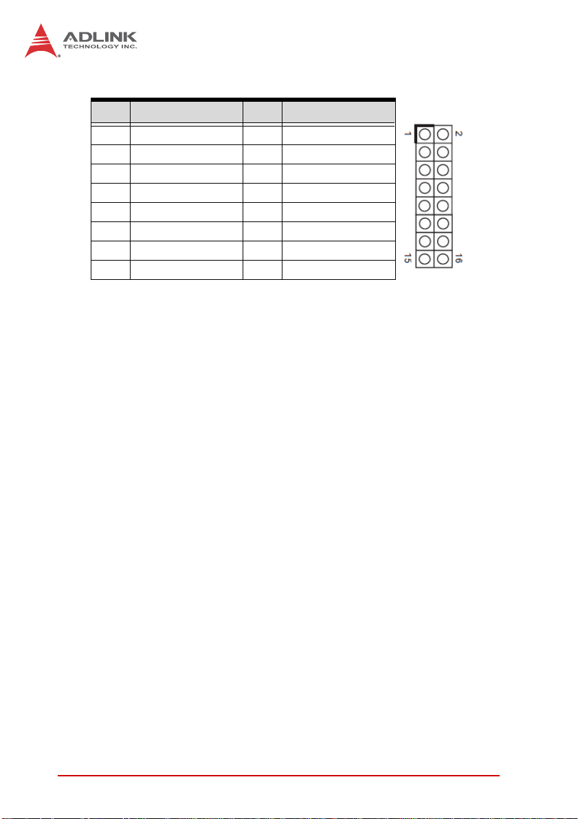
Digital IO Header (DGIO1)
Pin # Signal Pin # Signal
1 Digital Output 0 2 Digital Input 0
3 Digital Output 1 4 Digital Input 1
5 Digital Output 2 6 Digital Input 2
7 Digital Output 3 8 Digital Input 3
9 Digital Output 4 10 Digital Input 4
1 1 Digital Output 5 12 Digital Input 5
13 Digital Output 6 14 Digital Input 6
15 +5V 16 GND
This page intentionally left blank.
36 Hardware Information
Page 49

MIX-110
Important Safety Instructions
For user safety, please read and follow all instructions,
WARNINGS, CAUTIONS, and NOTES marked in this manual
and on the associated equipment before handling/operating the
equipment.
X Read these safety instructions carefully.
X Keep this user’s manual for future reference.
X Read the specifications section of this manual for detailed
information on the operating environment of this equipment.
X When installing/mounting or uninstalling/removing
equipment:
Z Turn off power and u nplug any power cords/cables.
X To avoid electrical shock and/or damage to equipment:
Z Keep equipment away from water or liquid sources;
Z Keep equipment away from high heat or high humidity;
Z Keep equipment properly ventilated (do not block or
cover ventilation openings);
Z Make sure to use recommended voltage and powe r
source settings;
Z Always install and operate equipment near an easily
accessible electrical socket-outlet;
Z Secure the power cord (do not place any obje ct on /ove r
the power cord);
Z Only install/attach and operate equipment on stable
surfaces and/or recommended mountings; and,
Z If the equipment will not be used for long periods of time,
turn off and unplug the equipment from its power source.
Important Safety Instructions 37
Page 50

X Never attempt to fix the equipment. Equipmen t sho u ld on ly
be serviced by qualified personnel.
A Lithium-type battery may be provided for uninterrupted, backup
or emergency power.
Risk of explosion if battery is replaced with one of an incorrect
WARNING:
type. Dispose of used batteries appropriately.
X Equipment must be serviced by authorized technicians
when:
Z The power cord or plug is damaged;
Z Liquid has penetrated the equipment;
Z It has been exposed to high humidity/moisture;
Z It is not functioning or does not function according to the
user’s manual;
Z It has been dropped and/or damaged; and/or,
Z It has an obvious sign of breakage.
38 Important Safety Instructions
Page 51

Getting Service
Contact us should you require any service or assistance.
ADLINK Technology, Inc.
Address: 9F, No.166 Jian Yi Road, Zhonghe District
New Taipei City 235, Taiwan
ᄅקؑխࡉ৬ԫሁ 166 ᇆ 9 ᑔ
Tel: +886-2-8226-5877
Fax: +886-2-8226-5717
Email: service@adlinktech.com
Ampro ADLINK Technology, Inc.
Address: 5215 Hellyer Avenue, #110, San Jose, CA 95138, USA
Tel: +1-408-360-0200
Toll Free: +1-800-966-5200 (USA only)
Fax: +1-408-360-0222
Email: info@adlinktech.com
ADLINK Technology (China) Co., Ltd.
Address: Ϟ⍋Ꮦ⌺ϰᮄᓴ∳催⾥ᡔು㢇䏃 300 ো(201203)
300 Fang Chun Rd., Zhangjiang Hi-Tech Park,
Pudong New Area, Shanghai, 201203 China
Tel: +86-21-5132-8988
Fax: +86-21-5132-3588
Email: market@adlinktech.com
MIX-110
ADLINK Technology Beijing
Address: ࣫ҀᏖ⍋⎔Ϟഄϰ䏃 1 োⲜ߯ࡼ E ᑻ 801 ᅸ(100085)
Tel: +86-10-5885-8666
Fax: +86-10-5885-8626
Email: market@adlinktech.com
ADLINK Technology Shenzhen
Address: ⏅ഇᏖቅ⾥ᡔು催ᮄϗ䘧᭄ᄫᡔᴃು
Tel: +86-755-2643-4858
Fax: +86-755-2664-6353
Email: market@adlinktech.com
LiPPERT ADLINK Technology GmbH
Address: Hans-Thoma-Strasse 11, D-68163, Mannheim, Germany
Tel: +49-621-43214-0
Fax: +49-621 43214-30
Email: emea@adlinktech.com
Rm. 801, Power Creative E, No. 1, B/D
Shang Di East Rd., Beijing, 100085 China
A1 2 ὐ C (518057)
2F, C Block, Bldg. A1, Cyber-Tech Zone, Gao Xin Ave. Sec. 7,
High-Tech Industrial Park S., Shenzhen, 518054 China
Getting Service 39
Page 52

ADLINK Technology, Inc. (French Liaison Office)
Address: 15 rue Emile Baudot, 91300 Massy CEDEX, France
Tel: +33 (0) 1 60 12 35 66
Fax: +33 (0) 1 60 12 35 66
Email: france@adlinktech.com
ADLINK Technology Japan Corporation
Address: ͱ101-0045 ᵅҀ䛑ҷ⬄⼲⬄䤯ފ⬎ 3-7-4
Tel: +81-3-4455-3722
Fax: +81-3-5209-6013
Email: japan@adlinktech.com
ADLINK Technology, Inc. (Korean Liaison Office)
Address: 昢殾柢 昢爎割 昢爎壟 1675-12 微汾瘶捒娯 8猻
Tel: +82-2-2057-0565
Fax: +82-2-2057-0563
Email: korea@adlinktech.com
ADLINK Technology Singapore Pte. Ltd.
Address: 84 Genting Lane #07-02A, Cityneon Design Centre,
Tel: +65-6844-2261
Fax: +65-6844-2263
Email: singapore@adlinktech.com
ADLINK Technology Singapore Pte. Ltd. (Indian Liaison Office)
Address: 1st Floor, #50-56 (Between 16th/17th Cross) Margosa Plaza,
Tel: +91-80-65605817, +91-80-42246107
Fax: +91-80-23464606
Email: india@adlinktech.com
⼲⬄ 374 ɛɳ 4F
KANDA374 Bldg. 4F, 3-7-4 Kanda Kajicho,
Chiyoda-ku, Tokyo 101-0045, Japan
8F Mointer B/D,1675-12, Seocho-Dong, Seocho-Gu,
Seoul 137-070, Korea
Singapore 349584
Margosa Main Road, Malleswaram, Bangalore-560055, India
ADLINK Technology, Inc. (Israeli Liaison Office)
Address: 6 Hasadna St., Kfar Saba 44424, Israel
Tel: +972-9-7446541
Fax: +972-9-7446542
Email: israel@adlinktech.com
40 Getting Service
 Loading...