

Page 1

MilSystem
TM
User’s Guide
P/N 50-1Z028-1010
Page 2
Notice Page
DISCLAIMER
ADLINK Technology, Incorporated makes no representations or warranties with respect to the contents of
this manual or of the associated ADLINK products, and specifically disclaims any implied warranties of
merchantability or fitness for any particular purpose. ADLINK shall under no circumstances be liable for
incidental or consequential damages or related expenses resulting from the use of this product, even if it has
been notified of the possibility of such damages. ADLINK reserves the right to revise this publication from
time to time without obligation to notify any person of such revisions. If errors are found, please contact
ADLINK at the address listed below this disclaimer.
TRADEMARKS
CoreModule and the Ampro logo are registered trademarks, and ADLINK, Little Board, LittleBoard,
MightyBoard, MightySystem, MilSystem, MiniModule, ReadyBoard, ReadyPanel, ReadySystem, and
RuffSystem are trademarks of ADLINK Technology, Inc. All other marks are the property of their
respective companies.
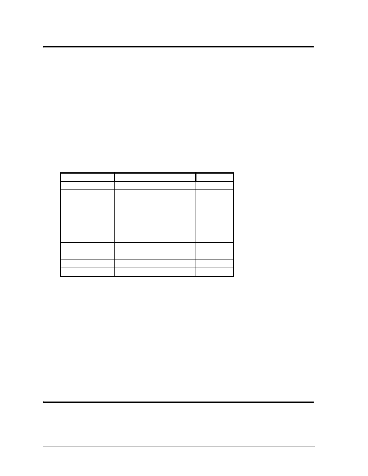
REVISION HISTORY
Revision Reason for Change Date
1.0 Initial Release Oct/09
1010 Added QuickDrive to Figure 1; added
pinout diagram for
DC In connector to Table 6; added
Caution to table 6 that monitor must be
connected first; changed revision of this
document from 1.0 to 1010; revised
Shanghai address in Appendix A
July/10
ADLINK Technology, Incorporated
5215 Hellyer Avenue, #110
San Jose, CA 95138-1007
Tel. 408 360-0200
Fax 408 360-0222
www.adlinktech.com
© Copyright 2009, 2010 ADLINK Technology, Incorporated
Audience
This manual provides reference only for computer design engineers, including but not limited to hardware
and software designers and applications engineers. ADLINK Technology, Inc. assumes you are qualified to
design and implement prototype computer equipment.
ii User’s Guide MilSystem
Page 3

Contents
MilSystem Setup .................................................................................................................................1
About the MilSystem ........................................................................................................................1
Using this Guide .........................................................................................................................1
Requirements .............................................................................................................................1
Device/Peripheral Connections ..................................................................................................2
Power Specifications ..................................................................................................................2
Environmental Specifications......................................................................................................4
What’s in the Box........................................................................................................................5
Setup Steps .....................................................................................................................................6
Setting Up the Work Space .......................................................................................................6
Installing Mounting Hardware .....................................................................................................7
Connecting Peripherals ..............................................................................................................8
MC (Military Connector) Pin Definitions ......................................................................................9
Applying Power to the MilSystem .............................................................................................16
Appendix A Technical Support...................................................................................................19
Appendix B Physical Dimensions ..............................................................................................21
List of Figures
Figure 1. MilSystem Unit with Accessory Kit...........................................................................5
Figure 2. Top View of Enclosure with Mounting Dimensions ..................................................7
Figure 3. Flat View of MilSystem I/O Panel.............................................................................8
Figure B-1. Width, Depth, and Height Measurements ..............................................................21
List of Tables
Table 1. System Power Requirements (LittleBoard 735, 1.6 GHz Atom CPU)......................2
Table 2. System Power Requirements (COM 840, 1.6 GHz Core
Table 3. System Power Requirements (LittleBoard 800, 1.4 GHz Pentium M CPU) .............4
Table 4. Environmental Requirements...................................................................................4
Table 5. Preparations.............................................................................................................6
Table 6. I/O Panel Connectors...............................................................................................9
Table 7. MC-1 Connector Pin Signals....................................................................................9
Table 8. MC-2 Connector Pin Signals..................................................................................11
Table 9. MC-3 Connector Pin Signals..................................................................................13
Table A-1. Technical Support Contact Information..................................................................19
TM
2 Duo CPU) ................3
MilSystem User’s Guide iii
Page 4

Contents
iv User’s Guide MilSystem
Page 5

MilSystem Setup
About the MilSystem
The MilSystem products are intended for users of turn-key embedded systems who require long life-cycle,
configuration controlled computers with MIL-STD-D38999 connectors. MilSystem models each feature one
of three Extreme Rugged™ computer boards: the LittleBoard 735 Single Board Computer (SBC), the
LittleBoard 800 SBC, or the COM 840 (Computer On Module) with the EBX baseboard. The
LittleBoard 735, LittleBoard 800, and the COM 840 are available with varieties of processors and memory.
An optional operating system (OS) can be pre-loaded onto an optional internal storage device (2 ½" hard
drive or Solid State Drive). Board Support Packages (BSPs) are provided on the optional Support Software
DVDs or QuickDrives™ to support additional OSs. Just use a USB memory device to load your application
software and you are ready to use your system.
Using this Guide
This guide provides the most efficient way to set up your MilSystem with your desired OS. The instructions
provided in this guide include:
• Removing the MilSystem from the shipping container and inspecting the accessories
• Connecting peripherals to the MilSystem
• Military connector pin signals and descriptions
• Powering up the MilSystem
Information not provided in this User’s Guide includes:
• Board or Module specifications
• Board or Module header pin signals and descriptions
• Operating system programming or operating instructions
NOTE Refer to OS manufacturers’ manuals for instructions when using OS software.
• Opening the MilSystem
• Replacing the Hard Disk Drive
Requirements
The following peripherals and devices are needed to make full use of the MilSystem.
• Peripherals (customer provided):
♦
USB or PS/2 keyboard
♦
USB or PS/2 mouse
♦
CRT or LCD monitor (VGA or LVDS)
NOTE These items are not available from ADLINK.
• Power Supply (optional):
♦
AC Adapter (with plug-type mating cord)
MilSystem User’s Guide 1
Page 6
MilSystem Setup
Device/Peripheral Connections
• Ethernet (LAN) connection
• USB device connections
• Up to two PC/104 expansion modules (except MilSystem with COM 840 module)
Power Specifications
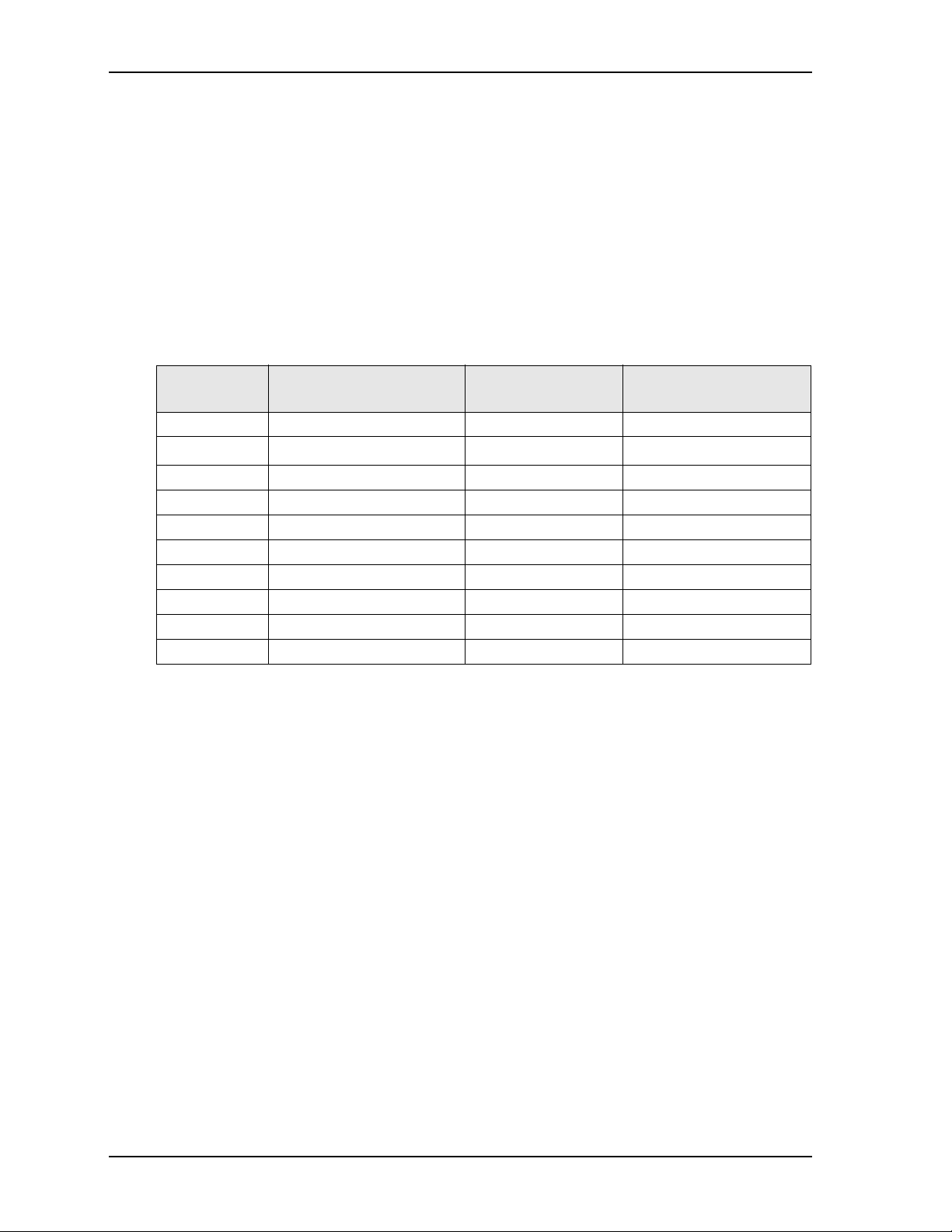
Tables 1 through 3 define the current draw values of the three MilSystem models, featuring either the
LittleBoard 735, COM 840 with EBX Baseboard, or the LittleBoard 800. The tables capture In-Rush, Idle,
and Burn-In-Test (BIT) currents at incremental input voltages from +14 to +32 VDC.
Tabl e 1 lists the current draw values of the MilSystem with the LittleBoard 735.
Table 1. System Power Requirements (LittleBoard 735, 1.6 GHz Atom CPU)
Input Type Maximum In-rush Current
(@ 170.88W Power)
+14VDC 12.21A 0.40A 0.51A
+16VDC 10.68A 0.35A 0.44A
+18VDC 9.49A 0.31A 0.40A
+20VDC 8.54A 0.28A 0.36A
+22VDC 7.77A 0.26A 0.32A
+24VDC 7.12A 0.24A 0.30A
+26VDC 6.57A 0.22A 0.27A
+28VDC 6.10A 0.20A 0.25A
+30VDC 5.70A 0.19A 0.24A
+32VDC 5.34A 0.18A 0.22A
Operating configurations:
Typical Idle Current
(@ 5.65W Power)
Typical BIT Current
(@ 7.11W Power)
• In-rush operating configuration includes one LittleBoard 735, 2GB DDR2 RAM, AMI BIOS, AC/DC
external digital power supply, DC/DC internal power module, CRT monitor, HDD, keyboard and
mouse.
• Idle operating configuration includes the same items as the In-rush configuration.
• BIT (Burn-In-Test) operating configuration includes the same items as the Idle configuration as well as
four serial loop backs, one parallel port with loop back, two Ethernet connections, four external USB
flash drives, and one Compact Flash card.
2 User’s Guide MilSystem
Page 7

MilSystem Setup
Tabl e 2 lists the current draw values of the MilSystem with the COM 840 and the EBX Baseboard.
Table 2. System Power Requirements (COM 840 with EBX Baseboard, 1.6 GHz CoreTM 2 Duo CPU)
Input Type In-rush Current
(@ 104.26W Power)
+14VDC 7.45A 2.71A 3.46A
+16VDC 6.52A 2.38A 3.03A
+18VDC 5.79A 2.11A 2.69A
+20VDC 5.21A 1.90A 2.42A
+22VDC 4.74A 1.73A 2.20A
+24VDC 4.34A 1.58A 2.02A
+26VDC 4.01A 1.46A 1.86A
+28VDC 3.72A 1.36A 1.73A
+30VDC 3.48A 1.27A 1.61A
+32VDC 3.26A 1.19A 1.51A
Operating configurations:
Typical Idle Current
(@ 37.96W Power)
Typical BIT Current
(@ 48.43W Power)
• In-rush operating configuration includes one COM 840, 2GB DDR2 RAM, AMI BIOS, EBX
Baseboard, AC/DC external digital power supply, DC/DC internal power module, LCD monitor, SATA
2.5" HDD, keyboard and mouse.
• Idle operating configuration includes the same items as the In-rush configuration.
• BIT (Burn-In-Test) operating configuration includes the same items as the Idle configuration as well as
four serial loop backs, one parallel port with loop back, two Ethernet connections, and four external
USB Compact Flash loop backs.
MilSystem User’s Guide 3
Page 8
Tabl e 3 lists the current draw values of the MilSystem with the LittleBoard 800.
Table 3. System Power Requirements (LittleBoard 800, 1.4 GHz Pentium M CPU)
MilSystem Setup
Input Type In-rush Current
(@ 170.88W Power)
+14VDC 12.21A 0.68A 0.94A
+16VDC 10.68A 0.60A 0.82A
+18VDC 9.49A 0.53A 0.73A
+20VDC 8.54A 0.48A 0.66A
+22VDC 7.77A 0.43A 0.60A
+24VDC 7.12A 0.40A 0.55A
+26VDC 6.57A 0.37A 0.51A
+28VDC 6.10A 0.34A 0.47A
+30VDC 5.70A 0.32A 0.44A
+32VDC 5.34A 0.30A 0.41A
Operating configurations:
Typical Idle Current
(@ 9.54W Power)
Typical BIT Current
(@ 13.18W Power)
• In-rush operating configuration includes one LittleBoard 800, 1GB DDR RAM, AMI BIOS, AC/DC
external digital power supply, DC/DC internal power module, CRT monitor, HDD, keyboard and
mouse.
• Idle operating configuration includes the same items as the In-rush configuration.
• BIT (Burn-In-Test) operating configuration includes the same items as the Idle configuration as well as
four serial loop backs, one parallel port with loop back, two Ethernet connections, four external USB
flash drives, and one Compact Flash card.
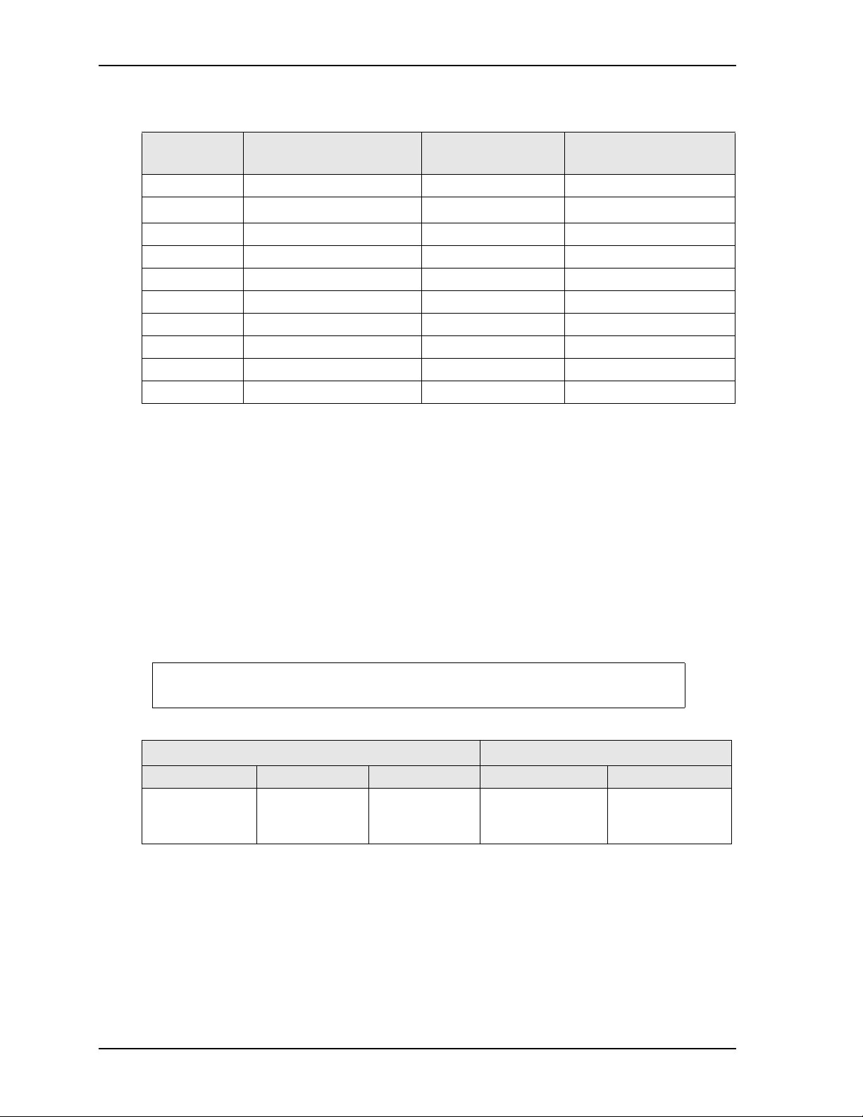
Environmental Specifications
Tabl e 4 provides the most efficient operating and storage condition ranges required for this system with the
LittleBoard 735, LittleBoard 800, and COM 840.
NOTE Extended temperature range available only on extended temperature tested
(ETT) systems.
Table 4. Environmental Requirements
Temperature Humidity
Operating Storage Extended Operating Non-operating
-20° to +65°C
(-4° to +149°F)
–55° to +85°C
(–67° to +185°F)
–40° to +75°C
(–40° to +167°F)
5% to 90%
relative humidity,
non-condensing
5% to 95%
relative humidity,
non-condensing
4 User’s Guide MilSystem
Page 9

What’s in the Box
MC-3
MC-2
MC-1
POWER
4
7
4
0
2
5
3
2
17
10
4
1
3
9
16
24
31
3
9
46
52
5
5
53
4
7
4
0
2
5
3
2
17
10
4
1
3
9
16
24
31
39
46
52
55
53
4
7
4
0
2
5
3
2
17
10
4
1
3
9
16
24
31
39
46
52
55
53
B
AD
C
8
-
4
MilSystem_ShipContents_b
SATA
The Contents List identifies the items in the shipping box for the MilSystem Unit and the MilSystem
Accessory Kit (sold separately.) See Figure 1.
MilSystem Unit
Cooling Fins
(Pre-Installed)
MilSystem Setup
Mounting Flange[4] (Pre-Installed)
MilSystem Accessory Kit (Mil-Acc, sold separately)
AC Adapter
MC-1
Breakout
Cable
DC Cable
Connector
Support
Software
QuickDrive
MC-2
Breakout
Cable
MC-3
Breakout
Cable
AC
Cable
Mating
Figure 1. MilSystem Unit with Accessory Kit
MilSystem User’s Guide 5
Page 10

MilSystem Setup
Setup Steps
Follow the setup steps in this section in the order listed. Skip any steps that do not apply to your application.
References to other ADLINK manuals are provided in this section for more information about installation
and use of this MilSystem.
Table 5. Preparations
1) Open shipping box.
2) Verify contents.
3) Obtain support
documentation.
• Locate the MilSystem Contents List.
• Unpack the contents of the shipping box.
• Verify the contents of the shipping box against the Contents List included
with your MilSystem.
• If anything is missing or damaged, call your sales representative. Refer to
the Ampro By ADLINK web page at http://www.adlinktech.com
for con-
tact information.
LittleBoard 735 Reference Manual
This document provides detailed information on the LittleBoard 735 and is
located on the Ampro By ADLINK web page at http://www.adlinktech.com
LittleBoard 800 Reference Manual
This document provides detailed information on the LittleBoard 800 and is
located on the Ampro By ADLINK web page at http://www.adlinktech.com
COM 840 Reference Manual
.
.
This document provides detailed information on the COM 840 and is located
on the Ampro By ADLINK web page at http://www.adlinktech.com
Setting Up the Work Space
NOTE To prevent damage to the MilSystem, ensure sufficient clearance exists around
the cooling fins for unrestricted airflow. See Figure 1 on page 5.
The air temperature inside the enclosure could rise above the specified operating
temperature limits if the airflow through the cooling fins is restricted.
4) Select workbench
location.
5) Unpack MilSystem.
• The workbench location should be a flat clean surface for setup and opera-
tion (including the connection of any external peripherals and optional
devices).
• Ensure sufficient airflow clearance exists around the complete enclosure.
• Remove the MilSystem from its shipping container and place it on a flat
work surface.
• The MilSystem enclosure combined with LittleBoard or COM module,
storage (HDD, CF, or SSD), and the desired OS form a complete system,
ready for operation.
.
6 User’s Guide MilSystem
Page 11

Installing Mounting Hardware
6) Install mounting screws
(1/4"-20 [6.35mm].)
• Install mounting screws (not included) for surface or wall mounting to
the four mounting flanges of the MilSystem. See Figure 2.
C
L
7,36"
187 mm
5.51"
140 mm
MilSystem Setup
C
L
C
L
12.20"
310 mm
11.02"
280 mm
8.18"
208 mm
Figure 2. Top View of Enclosure with Mounting Dimensions
10.00"
254 mm
C
L
MilSystem User’s Guide 7
Page 12

Connecting Peripherals
7) Connect the MC-1 cable
to the MilSystem. See
Figure 1 on page 5 for
illustrations of cables. See
Figure 3 for locations of
the MC connectors.
MilSystem Setup
• Refer to Figure 3 for locations and descriptions of the connectors before
making connections or powering on the MilSystem.
• Connect the USB or PS2 keyboard to the appropriate connector on the
MC-1 connector.
• Connect the USB mouse (PS2 not supported) to the appropriate connec-
tor on the MC-1 connector.
• Connect the CRT or LCD monitor through its 15-pin cable to the VGA
cable on the MC-1 connector.
CAUTION The monitor must be connected to the MilSystem before
you power on the system, or the display ouput
automatically will switch from VGA to LVDS.
MC-3 - Parallel
and LVDS
17
10
25
32
40
4
47
1
53
3
55
9
52
16
46
31
24
39
47
53
55
52
MC-3 MC-2
MC-2 - USB3,
USB4, Fast
Ethernet, and
RS232/485/422
COM Ports
Figure 3. Flat View of MilSystem I/O Panel
17
10
25
32
40
4
1
3
9
16
46
31
24
39
17
10
25
32
40
4
47
1
53
3
55
9
52
16
46
31
24
39
AD
B
C
8-4
DC
Power
In
MC-1 POWER
MC-1 - VGA, Ethernet,
PS2 Keyboard, Stereo
Audio Out, Stereo Line In,
Mic In, Power Button,
Reset Button, Power LED,
HDD Activity LED, SATA,
USB1 and USB2
8 User’s Guide MilSystem
Page 13

MilSystem Setup
Table 6. I/O Panel Connectors (Refer to Figure 3 for connector locations.)
Control/Connector Description
MC-1 This military connector provides signals for VGA, Ethernet, PS2 Keyboard,
Stereo Audio Out, Stereo Line In, Mic In, ACPI Power In, Reset In, Power On
LED, HDD Activity LED, SATA, USB 2.0.
MC-2 This military connector provides signals for USB 2.0, Ethernet, and RS232/
485/422 COM Ports.
MC-3 This military connector provides signals for Parallel and LVDS.
DC Power In This Military Power connector accepts DC voltages from an external source. This
connector is available in two versions depending on the MilSystem model:
V+
• The MILxxx models provide +12VDC to +25VDC power connectors.
• The MILxxxW models provide +14VDC to +32VDC power connectors.
AD
B
C
8-4
Ground
NOTE This connector is manufactured by Amphenol,
P/N PT06E-8-4S(023).
NOTE To connect a Hard Disk Drive (HDD) or CD-ROM to the MilSystem, use
one of the USB or SATA ports to connect the device.
MC (Military Connector) Pin Definitions
The following three tables break down the signals of the three military I/O connectors (MC) on the
MilSystem. Each table lists the MC pin number, the mating breakout cable connector, the breakout cable
connector pin number, and the signal name and description of each pin on the military connector.
Table 7. MC-1 Connector Pin Signals
MC
Pin #
1 VGA 1 RED Red Analog Output
2 VGA 6 GND1 Ground
3 VGA 2 GREEN Green Analog Output
4 VGA 7 GND2 Ground
5 VGA 3 BLUE Blue Analog Output
6 VGA 8 GND3 Ground
7 VGA 13 HSYNC Horizontal Sync
8 VGA 10 GND4 Ground
9 VGA 14 VSYNC Vertical Sync
10 VGA 9 PWR Power
11* VGA 12 SDA Display Data Channel
12* VGA 15 SCL Display Data Channel
Breakout Cable
Connector
Breakout
Cable Pin #
Signal Signal Description
NC 4 Not connected
NC 5 Not connected
(DDC) - Data
(DDC) - Clock
MilSystem User’s Guide 9
Page 14

Table 7. MC-1 Connector Pin Signals (Continued)
MilSystem Setup
MC
Pin #
Breakout Cable
Connector
Breakout
Cable Pin #
Signal Signal Description
13 Ethernet 1 MDI0_P Ethernet0 Positive
14 Ethernet 2 MDI0_N Ethernet0 Negative
15 Ethernet 3 MDI1_P Ethernet1 Positive
16 Ethernet 4 MDI2_P Ethernet2 Positive
17 Ethernet 5 MDI2_N Ethernet2 Negative
18 Ethernet 6 MDI1_N Ethernet1 Negative
19 Ethernet 7 MDI3_P Ethernet3 Positive
20 Ethernet 8 MDI3_N Ethernet3 Negative
21 USB1 1 USBPWR1 Power
22 USB1 2 USBP-1 Data Negative
23 USB1 3 USBP+1 Data Positive
24 USB1 4 USBGND1 Ground
25 USB1 SH SHIELD USB1 Shield
26 USB2 1 USBPWR2 Power
27 USB2 2 USBP-2 Data Negative
28 USB2 3 USBP+2 Data Positive
29 USB2 4 USBGND2 Ground
35 USB2 SH SHIELD USB2 Shield
30 PS2 1 KBD_DATA Keyboard Data
31 PS2 SH KBD_SHIELD Keyboard Shield
32 PS2 3 GND4 Ground
33 PS2 4 KBD_PWR (VCC) Keyboard Power
34 PS2 5 KBD_CLK Keyboard Clock
36 Green Audio 1 HP_L Stereo Audio Out Left
37 Green Audio 2 HP_R Stereo Audio Out Right
38 Green Audio 3 HP_GND Stereo Audio Out
Ground
39 Pink Audio 1 MIC1_IN Microphone In
40 Pink Audio 3 MIC_GND Microphone Ground
41 Pink Audio 2 MIC_REF Microphone Reference
42 Blue Audio 1 LINE_IN_L Stereo Line In Left
Channel
43 Blue Audio 3 LINE_IN_GND Stereo Line In Ground
44 Blue Audio 2 LINE_IN_R Stereo Line In Right
Channel
45 Push button 1 PowerOn Powers On the system
50 Push button 2 GND Ground
46 Push button 1 Reset Resets the system
50 Push button 2 GND Ground
10 User’s Guide MilSystem
Page 15

Table 7. MC-1 Connector Pin Signals (Continued)
MilSystem Setup
MC
Pin #
Breakout Cable
Connector
Breakout
Cable Pin #
Signal Signal Description
47 LED (Green) 1 PowerLED Indicates Power On
50 LED (Green) 2 GND Ground
48** LED (Red) 2 HDDLED (Cathode) Indicates Hard Drive
Activity
49** LED (Red) 1 HDDLED_+5V (Anode) Indicates Hard Drive
Activity
51*** SATA 2 SATA_TXP0 SATA0 Transmit
Positive
52*** SATA 3 SATA_TXN0 SATA0 Transmit
Negative
53*** SATA 1, 4, 7 SATA_GND Ground
54*** SATA 5 SATA_RXN0 SATA0 Receive
Negative
55*** SATA 6 SATA_RXP0 SATA0 Receive
Positive
*Supported only on MilSystem 735
**Supported only on MilSystem 840
***Supported only on MilSystems 735 and 840
Table 8. MC-2 Connector Pin Signals
Pin # Breakout Cable
Connector
1 USB3 1 USBPWR3 Power
2 USB3 2 USBP-3 Data Negative
3 USB3 3 USBP+3 Data Positive
4 USB3 4 USBGND3 Ground
5 USB3 SH SHIELD3 Shield
6 USB4 1 USBPWR4 Power
7 USB4 2 USBP-4 Data Negative
8 USB4 3 USBP+4 Data Positive
9 USB4 4 USBGND4 Ground
55 USB4 SH SHIELD4 Shield
10 Ethernet 1 MDI0_P Ethernet0 Positive
11 Ethernet 2 MDI0_N Ethernet0 Negative
12 Ethernet 3 MDI1_P Ethernet1 Positive
13 Ethernet 4 MDI2_P Ethernet2 Positive
14 Ethernet 5 MDI2_N Ethernet2 Negative
15 Ethernet 6 MDI1_N Ethernet1 Negative
16 Ethernet 7 MDI3_P Ethernet3 Positive
17 Ethernet 8 MDI3_N Ethernet3 Negative
Breakout
Cable Pin #
Signal Signal Description
MilSystem User’s Guide 11
Page 16

Table 8. MC-2 Connector Pin Signals (Continued)
MilSystem Setup
Pin # Breakout Cable
Connector
Breakout
Cable Pin #
Signal Signal Description
54 Ethernet SH SHIELD Ethernet0, 1, 2, 3 Shield
18 Serial 1 1 DCD1 Indicates external serial device is
detecting a carrier signal.
19 Serial 1 2 RXD1 Receive Data
20 Serial 1 3 TXD1 Transmit Data
21 Serial 1 4 DTR1 Indicates port is powered, initialized,
and ready.
22 Serial 1 5 GND1 Ground
23 Serial 1 6 DSR1 Indicates external serial device is
powered, initialized, and ready.
24 Serial 1 7 RTS1 Indicates port is ready to transmit data.
25 Serial 1 8 CTS1 Indicates external serial device is ready
to receive data.
26 Serial 1 9 RI1 Indicates external serial device is
detecting a ring condition.
27 Serial 2 1 DCD2 Indicates external serial device is
detecting a carrier signal.
28 Serial 2 2 RXD2 Receive Data
29 Serial 2 3 TXD2 Transmit Data
30 Serial 2 4 DTR2 Indicates port is powered, initialized,
and ready.
31 Serial 2 5 GND2 Ground
32 Serial 2 6 DSR2 Indicates external serial device is
powered, initialized, and ready.
33 Serial 2 7 RTS2 Indicates port is ready to transmit data.
34 Serial 2 8 CTS2 Indicates external serial device is ready
to receive data.
35 Serial 2 9 RI2 Indicates external serial device is
detecting a ring condition.
36 Serial 3 1 DCD3 Indicates external serial device is
detecting a carrier signal.
37 Serial 3 2 RXD3 Receive Data
38 Serial 3 3 TXD3 Transmit Data
39 Serial 3 4 DTR3 Indicates port is powered, initialized,
and ready.
40 Serial 3 5 GND3 Ground
41 Serial 3 6 DSR3 Indicates external serial device is
powered, initialized, and ready.
42 Serial 3 7 RTS3 Indicates port is ready to transmit data.
43 Serial 3 8 CTS3 Indicates external serial device is ready
to receive data.
44 Serial 3 9 RI3 Indicates external serial device is
detecting a ring condition.
12 User’s Guide MilSystem
Page 17

Table 8. MC-2 Connector Pin Signals (Continued)
MilSystem Setup
Pin # Breakout Cable
Connector
45 Serial 4 1 DCD4 Indicates external serial device is
46 Serial 4 2 RXD4 Receive Data
47 Serial 4 3 TXD4 Transmit Data
48 Serial 4 4 DTR4 Indicates port is powered, initialized,
49 Serial 4 5 GND4 Ground
50 Serial 4 6 DSR4 Indicates external serial device is
51 Serial 4 7 RTS4 Indicates port is ready to transmit data.
52 Serial 4 8 CTS4 Indicates external serial device is ready
53 Serial 4 9 RI4 Indicates external serial device is
54 Ethernet SH SHIELD Ethernet0, 1, 2, 3 Shield
55 USB4 SH SHIELD4 USB4 Shield
Table 9. MC-3 Connector Pin Signals
Breakout
Cable Pin #
Signal Signal Description
detecting a carrier signal.
and ready.
powered, initialized, and ready.
to receive data.
detecting a ring condition.
Pin # Breakout Cable
Connector
Breakout
Cable Pin #
Signal Signal Description
1 Parallel 1 STB Strobe - used to strobe data
into a printer.
2 Parallel 2 PD0 Parallel Port Data 0 signal
3 Parallel 3 PD1 Parallel Port Data 1 signal
4 Parallel 4 PD2 Parallel Port Data 2 signal
5 Parallel 5 PD3 Parallel Port Data 3 signal
6 Parallel 6 PD4 Parallel Port Data 4 signal
7 Parallel 7 PD5 Parallel Port Data 5 signal
8 Parallel 8 PD6 Parallel Port Data 6 signal
9 Parallel 9 PD7 Parallel Port Data 7 signal
10 Parallel 10 ACK Acknowledge - indicates
data from the printer has
been received and ready for
new data if signal state is
Low.
11 Parallel 11 BSY Busy - indicates printer is
not ready to accept data if
signal state is High.
12 Parallel 12 PE Paper End - indicates
printer is out of paper if
signal state is High.
MilSystem User’s Guide 13
Page 18

Table 9. MC-3 Connector Pin Signals (Continued)
MilSystem Setup
Pin # Breakout Cable
Connector
Breakout
Cable Pin #
Signal Signal Description
13 Parallel 13 SLCT Select - indicates the printer
is selected and powered on
if the signal state is High.
14 Parallel 14 AFD Auto Feed - requests the
printer to automatically
feed one line after each line
is printed.
15 Parallel 15 ERR Error - status output from
the printer, indicating an
error condition exists on the
printer if the signal state is
Low.
16 Parallel 16 INIT Initialize - used to initialize
the printer. Output in
standard Mode, I/O in ECP/
EPP mode.
17 Parallel 17 SLIN Select In – used to select
the printer. I/O pin in ECP/
EPP mode.
18 Parallel 18 GND Ground
19 Parallel 19 GND Ground
20 Parallel 20 GND Ground
21 Parallel 21 GND Ground
22 Parallel 22 GND Ground
23 Parallel 23 GND Ground
24 Parallel 24 GND Ground
25 Parallel 25 GND Ground
26 LVDS 1 VCC_12VP +12 volt input
27 LVDS 2 VCC_LVDS_CONN +3.3 volt or +5 volt input
28 LVDS 3 GND Ground
29 LVDS 4 GND Ground
30 LVDS 5 CLK_LVDS_IYBP Channel 2 clock positive
31 LVDS 6 CLK_LVDS_IYBM Channel 2 clock negative
32 LVDS 7 LVDS_IYBP3 Channel 2, line 3, data
positive
33 LVDS 8 LVDS_IYBM3 Channel 2, line 3, data
negative
34 LVDS 9 LVDS_IYBP2 Channel 2, line 2, data
positive
35 LVDS 10 LVDS_IYBM2 Channel 2, line 2, data
negative
36 LVDS 11 LVDS_IYBP1 Channel 2, line 1, data
positive
14 User’s Guide MilSystem
Page 19

Table 9. MC-3 Connector Pin Signals (Continued)
MilSystem Setup
Pin # Breakout Cable
Connector
Breakout
Cable Pin #
Signal Signal Description
37 LVDS 12 LVDS_IYBM1 Channel 2, line 1, data
negative
38 LVDS 13 LVDS_IYBP0 Channel 2, line 0, data
positive
39 LVDS 14 LVDS_IYBM0 Channel 2, line 0, data
negative
40 LVDS 15 LVDS_PANELBKLTCTL* Controls Panel Backlight
41 LVDS 16 LVDS_PANELVDDEN Enables Panel Power
42 LVDS 17 CLK_LVDS_IYAP Channel 1 clock positive
43 LVDS 18 CLK_LVDS_IYBM Channel 1 clock negative
44 LVDS 19 LVDS_IYAP3 Channel 1, line 3, data
positive
45 LVDS 20 LVDS_IYAM3 Channel 1, line 3, data
negative
46 LVDS 21 LVDS_IYAP2 Channel 1, line 2, data
positive
47 LVDS 22 LVDS_IYAM2 Channel 1, line 2, data
negative
48 LVDS 23 LVDS_IYAP1 Channel 1, line 1, data
positive
49 LVDS 24 LVDS_IYAM1 Channel 1, line 1, data
negative
50 LVDS 25 LVDS_IYAP0 Channel 1, line 0, data
positive
51 LVDS 26 LVDS_IYAM0 Channel 1, line 0, data
negative
52 LVDS 27 LVDS_DDCPCLK Display Data Channel
Clock
53 LVDS 28 LVDS_DDCPDATA Display Data Channel Data
54 LVDS 29 LVDS_PANELBKLTEN* Enable Panel Backlight
Inverter
55 LVDS 30 Chassis Shield
*Requires external display power supply and display power inverter.
MilSystem User’s Guide 15
Page 20

Applying Power to the MilSystem
MilSystem Setup
8) Follow these steps to apply
power to the MilSystem.
D
C
A
B
8-4
0
17
1
4
1
5
2
2
3
ER
0
4
W
7
4
3
PO
53
9
6
1
24
55
31
52
6
4
39
C-1
M
9) Verify the MilSystem
satisfactorily powers on.
• Connect the AC Mating Cable to the AC Adapter (options.) See
Figure 1 on page 5.
• Plug in the DC Cable Connector from the AC Adapter (option) to
the DC IN jack on the MilSystem. See Figure 3 on page 8.
NOTE Power supplied to the unit must be within the allowed range
depending on the model of the unit:
• +12VDC to +25VDC for MILxxx models
• +14VDC to +32VDC for MILxxxW models
Failure to provide proper power may damage the system and void
the warranty.
• Plug in the CRT or LCD monitor’s power cord to an AC outlet and
turn on the monitor.
CAUTION The monitor must be connected to the MilSystem
before you turn on the system, or the display output
automatically will switch from VGA to LVDS.
• Plug in the AC Mating cable to an AC outlet.
• Press the MilSystem Power On button on the MC-1 breakout cable
to power on the MilSystem.
• To enter the BIOS Setup, press the <Del> key during power-on self
test (POST).
Use BIOS Setup during the initial boot to set the desired options.
• You should see POST complete successfully before the system
starts loading the operating system (optional.) If you are using
Linux, the boot loader will appear first, similar to the one shown
below with the corresponding OS name displayed.
NOTE The optional 2 ½" hard disk drive comes with partitions for
the OS and swap space.
(The Linux 2.6 OS is shown as an example.)
GNU GRUB version 0.95 (632k lower/250768 upper memory)
Linux Kernel 2.6.x-xxx (recovery mode)
Use the and keys to se lect which entry is highlighted.
Press Enter to boot the se lected OS, ‘e’ to edit the
commands before booting, ‘a’ to modify the k ernel
arguments before booting, or ‘c’ for a command-line.
Sys Linux_Boot_a
RdySy2U_2 4a
16 User’s Guide MilSystem
Page 21

MilSystem Setup
10) Using the
Operating
System (OS)
• You should see a prompt on the monitor screen indicating the OS is load-
ing, or has loaded.
• Refer to the respective OS manual (not supplied by ADLINK.)
• Refer to the LittleBoard 735, LittleBoard 800, or COM 840 Support Soft-
ware DVDs or QuickDrives for additional drivers and instructions.
MilSystem User’s Guide 17
Page 22

MilSystem Setup
18 User’s Guide MilSystem
Page 23

Appendix A Technical Support
ADLINK Technology, Inc. provides a number of methods for contacting Technical Support listed in the
Tabl e A -1 below. Requests for support through the Ask an Expert web page are given the highest priority,
and usually are addressed within one working day.
• ADLINK Ask an Expert – This is a comprehensive support center designed to meet all your technical
needs. This service is free and available 24 hours a day through the Ampro By ADLINK web page at
http://www.adlinktech.com/AAE/
which will help you with the common information requested by most customers. This is a good source
of information to look at first for your technical solutions. However, you must register online if you
wish to use the Ask a Question feature.
ADLINK strongly recommends registering with the web site. By creating a profile on the ADLINK web
site, you will have a portal page called “My ADLINK” unique to you with access to exclusive services
and account information.
• Personal Assistance – You may also request personal assistance by creating an Ask an Expert account
and then going to the Ask a Question feature. Requests can be submitted 24 hours a day, 7 days a week.
You will receive immediate confirmation that your request has been entered. Once you have submitted
your request, you must log in to go to the My Question area where you can check status, update your
request, and access other features.
• Download Service – This service is also free and available 24 hours a day at
http://www.
register online before you can login to this service.
adlinktech.com. For certain downloads such as technical documents and software, you must
. This includes a searchable database of Frequently Asked Questions,
Table A-1. Technical Support Contact Information
Method Contact Information
Ask an Expert http://www.adlinktech.com/AAE/
Web Si t e http://www.adlinktech.com
Standard Mail
Contact us for any service or assistance.
ADLINK Technology, Inc.
Address: 9F, No.166 Jian Yi Road, Chungho City,
Taipei County 235, Taiwan
♿▦傲₼✛ゑㆉ恾 166 壮 9 㲢
Tel: +886-2-8226-5877
Fax: +886-2-8226-5717
Email: service@adlinktech.com
Ampro ADLINK Technology, Inc.
Address: 5215 Hellyer Avenue, #110, San Jose, CA 95138, USA
Tel: +1-408-360-0200
Toll Free: +1-800-966-5200 (USA only)
Fax: +1-408-360-0222
Email: info@adlinktech.com
ADLINK Technology (China) Co., Ltd.
Address: ₙ䀆ゑ㿵₫㠿◉ㆯ㻮浧䱠㔏⥼◉啂㢴恾 300 ⚆ (201203)
300 Fang Chun Rd., Zhangjiang Hi-Tech Park,
Pudong New Area, Shanghai, 201203 China
Tel: +86-21-5132-8988
Fax: +86-21-5132-3588
Email: market@adlinktech.com
MilSystem User’s Guide 19
Page 24

Appendix A Technical Support
Table A-1. Technical Support Contact Information (Continued)
ADLINK Technology Beijing
Address: ▦℻ゑ䀆䁏◉ₙ⦿₫恾 1 ⚆䥗⒪┷┪⮶☵ E ㄶ 801 ⸳(100085)
Rm. 801, Power Creative E, No. 1, B/D
Shang Di East Rd., Beijing, 100085 China
Tel: +86-10-5885-8666
Fax: +86-10-5885-8625
Email: market@adlinktech.com
ADLINK Technology Shenzhen
Address: 䂀⧂ゑ◦⼀◉䱠㔏⥼◦◉浧㠿◦ₒ拢 㟿ⷦ㔏㦾⥼
A1 㪚 2 㰋 C ◉ (518057)
2F, C Block, Bldg. A1, Cyber-Tech Zone, Gao Xin Ave. Sec. 7,
High-Tech Industrial Park S., Shenzhen, 518054 China
Tel: +86-755-2643-4858
Fax: +86-755-2664-6353
Email: market@adlinktech.com
ADLINK Technology, Inc. (German Liaison Office)
Address: Nord Carree 3, 40477 Duesseldorf, Germany
Tel: +49-211-495-5552
Fax: +49-211-495-5557
Email: emea@adlinktech.com
ADLINK Technology, Inc. (French Liaison Office)
Address: 15 rue Emile Baudot, 91300 Massy CEDEX, France
Tel: +33 (0) 1 60 12 35 66
Fax: +33 (0) 1 60 12 35 66
Email: france@adlinktech.com
ADLINK Technology Japan Corporation
Address: 151-0072 㨀℻掌䂚廆◉ヰዓ廆
1-1-2 㦬㡴䞮✌ヰዓ廆ኰወ 8F
Asahiseimei Hatagaya Bldg. 8F
1-1-2 Hatagaya, Shibuya-ku, Tokyo 151-0072, Japan
Tel: +81-3-4455-3722
Fax: +81-3-5333-6040
Email: japan@adlinktech.com
ADLINK Technology, Inc. (Korean Liaison Office)
Address: 끭겑 뚽霡 뚽鶎 1506-25 뼑鵹 B/D 2 럪
2F, Hando B/D, 1506-25, Seocho-Dong, Seocho-Gu,
Seoul 137-070, Korea
Tel: +82-2-2057-0565
Fax: +82-2-2057-0563
Email: korea@adlinktech.com
ADLINK Technology Singapore Pte. Ltd.
Address: 84 Genting Lane #07-02A, Cityneon Design Centre,
Singapore 349584
Tel: +65-6844-2261
Fax: +65-6844-2263
Email: singapore@adlinktech.com
ADLINK Technology Singapore Pte. Ltd. (Indian Liaison Office)
Address: No. 1357, "Anupama", Sri Aurobindo Marg, 9th Cross,
JP Nagar Phase I, Bangalore - 560078, India
Tel: +91-80-65605817
Fax: +91-80-22443548
Email: india@adlinktech.com
20 User’s Guide MilSystem
Page 25

Appendix B Physical Dimensions
Figure B-1 shows the MilSystem enclosure dimensions.
7,36"
12.20"
310 mm
187 mm
C
L
5.51"
140 mm
C
L
C
L
11.02"
280 mm
10.00"
254 mm
C
L
8.18"
208 mm
Figure B-1. Width, Depth, and Height Measurements
3.90"
99 mm
(+/- 2mm)
MilSystem User’s Guide 21
Page 26

Appendix B Physical Dimensions
22 User’s Guide MilSystem
 Loading...