

Page 1
IMB-T10
Intel® Atom™ Processor D2550
Industrial Mini-ITX Motherboard
User’s Manual
Manual Rev.: 2.00
Revision Date: February 24, 2014
Part No: 50-1X003-1000
Advance Technologies; Automate the World.
Page 2

Revision History
Revision Release Date Description of Change(s)
2.00 2014/02/24 Initial release
ii Revision History
Page 3

IMB-T10
Preface
Copyright 2014 ADLINK Technology Inc.
This document contains proprietary infor mation protected by copyright. All rights are reserved. No part of this manual may be reproduced by any mechanical, electronic, or other means in any form
without prior written permission of the manufacturer.
Disclaimer
The information in this document is subject to change without prior
notice in order to improve reliability, design, and function and does
not represent a commitment on the part of the manufa cturer.
In no event will the manufacturer be liable for direct, indirect, special, incidental, or consequential damages arising out of the use or
inability to use the product or documentation, even if advised of
the possibility of such damages.
Environmental Responsibility
ADLINK is committed to fulfill its social responsibility to global
environmental preservation through compliance with the European Union's Restriction of Hazardous Substances (RoHS) directive and Waste Electrical and Electronic Equipment (WEEE)
directive. Environmental protection is a top priority for ADLINK.
We have enforced measures to ensure that our products, manufacturing processes, components, and raw materials have as little
impact on the environment as possible. When products are at their
end of life, our customers are encouraged to dispose of them in
accordance with the product disposal and/or recovery programs
prescribed by their nation or company.
Trademarks
Product names mentioned herein are used for identification purposes only and may be trademarks and/or registered trademarks
of their respective companies.
Preface iii
Page 4

Using this Manual
Audience and Scope
The IMB-T10 User’s Manual is intended for hardware technicians
and systems operators with knowledge of installing, configuring
and operating industrial grade computers.
Manual Organization
This manual is organized as follows:
Preface: Presents copyright notifications, disclaimers, trade-
marks, and associated information on the proper usage of this
document and its associated product(s).
Chapter 1, Introduction: Introduces the IMB-T10, its features,
applications, and specifications, including functional descriptions
and board layout.
Chapter 2, Hardware Information: Provides technical information on connectors, jumpers and pin assignments for configuring
the IMB-T10.
Chapter 3, Getting Started: Describes how to install components
and drivers on the IMB-T10.
Chapter 4, BIOS Setup: Presents information and illustrations to
help understand and configure the system BIOS.
Appendix A, WDT Sample Code: Presents information on understanding and configuring the watchdog timer.
Important Safety Instructions: Presents safety instructions all
users must follow for the proper setup, installation and usage of
equipment and/or software.
Getting Service: Contact information for ADLINK’s worldwide
offices.
iv Preface
Page 5
IMB-T10
Conventions
Take note of the following conventions used throughout this
manual to make sure that users perform certain tasks and
instructions properly.
Additional information, aids, and tips that help users perform
tasks.
NOTE:
NOTE:
Information to prevent minor physical injury, component damage, data loss, and/or program corruption when trying to com-
CAUTION:
WARNING:
plete a task.
Information to prevent serious physical injury, component
damage, data loss, and/or program corruption when trying to
complete a specific task.
Preface v
Page 6

This page intentionally left blank.
vi Preface
Page 7

IMB-T10
Table of Contents
Revision History...................................................................... ii
Preface.................................................................................... iii
List of Figures........................................................................ ix
List of Tables.......................................................................... xi
1 Introduction ........................................................................ 1
1.1 Package Contents ............................................................... 1
1.2 Overview.............................................................................. 2
1.3 Features............................................................................... 2
1.4 Specifications....................................................................... 3
1.5 Block Diagram ..................................................................... 5
1.6 Functional Description ......................................................... 6
1.7 Mechanical Dimensions....................................................... 8
2 Hardware Information........................................................ 9
2.1 Rear I/O Layout ................................................................... 9
2.2 Rear I/O Connector Pin Definitions.................................... 10
2.3 Board Layout ..................................................................... 14
2.4 Onboard Connector Pin Definitions ................................... 16
2.5 Jumper Settings................................................................. 25
3 Getting Started ................................................................. 27
3.1 Screw Holes....................................................................... 27
3.2 Pre-installation Precautions............................................... 27
3.3 Installation of Memory Modules (SO-DIMM)...................... 28
3.4 Expansion Slots (PCI, PCI Express and Mini-PCIe/mSATA) 28
3.5 Driver Installation................................................. ... ... ... .... . 29
4 BIOS Setup........................................................................ 31
Table of Contents vii
Page 8

4.1 Introduction........................................................................ 31
4.1.1 UEFI Menu Bar..............................................................31
4.1.2 Navigation Keys.................. .... ... ... ... .... ... ... ....................32
4.2 Main Screen....................................................................... 33
4.3 Advanced Screen............................................................... 34
4.3.1 CPU Configuration.........................................................36
4.3.2 CPU Configuration.........................................................37
4.3.3 Storage Configuration....................................................39
4.3.4 Super IO Configuration..................................................40
4.3.5 ACPI Configuration........................................................41
4.3.6 USB Configuration.........................................................43
4.4 Hardware Health Event Monitoring System....................... 44
4.5 Boot Screen....................................................................... 46
4.6 Security Screen.................................................................. 47
4.7 Exit Screen......................................................................... 48
A Appendix: WDT Sample Code ..........................................51
Important Safety Instructions............................................... 55
Getting Service...................................................................... 57
viii Table of Contents
Page 9

IMB-T10
List of Figures
Figure 1-1: IMB-T10 Block Diagram................................................... 5
Figure 1-2: IMB-T10 Board Dimensions............................................. 8
Figure 2-1: IMB-T10 Rear I/O Layout................................................. 9
Figure 2-2: IMB-T10 Board Layout................................................... 14
List of Figures ix
Page 10

This page intentionally left blank.
xList of Figures
Page 11

IMB-T10
List of Tables
Table 1-1: IMB-T10 General Specifications........... ... ... .... ... ... ... .... ... . 4
Table 2-1: Board Layout Legend ....................................................15
List of Tables xi
Page 12

This page intentionally left blank.
xii List of Tables
Page 13

1 Introduction
This chapter will introduce the IMB-T10, its features, specifications, functional description, and mechanical layout.
1.1 Package Contents
Please check that your package contains the items below. If
you discover damaged or missing items, please contact your
vendor.
X IMB-T10 Mini-ITX Embedded Motherboard
X I/O shield
DO NOT install or apply power to equipment that is damaged
or if there is missing/incomplete equipment. Retain the ship-
WARNING:
ping carton and packing materials for inspection. Please contact your ADLINK dealer/vendor immediately for assistance.
Obtain authorization from your dealer before returning any
product to ADLINK.
IMB-T10
Introduction 1
Page 14

1.2 Overview
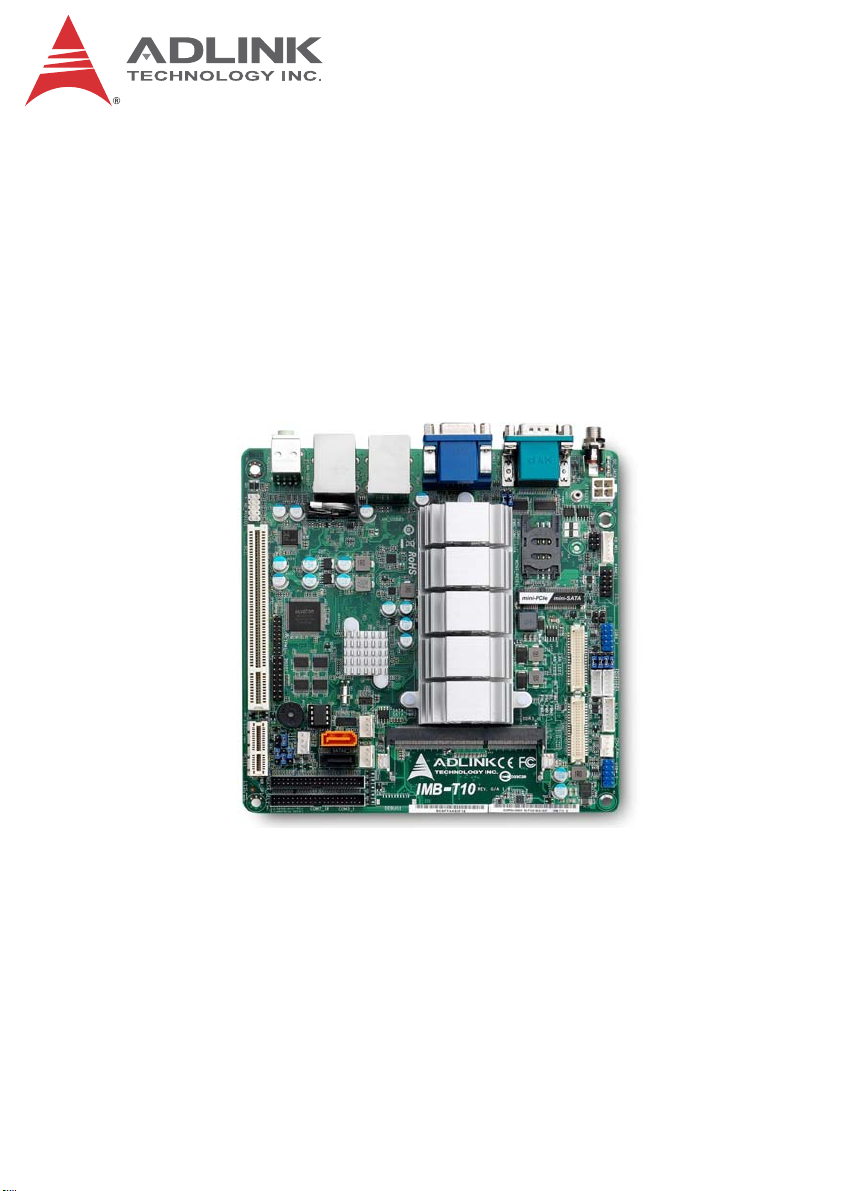
The ADLINK IMB-T10 is a Mini-ITX embedded motherboard
based on the Intel® Atom™ Processor D2550 built on 32-nm process technology in Micro-FCBGA118 packaging technologies and
the Mobile Intel® NM10 Express Chipset. The IMB-T10 is ideal for
embedded applications requiring fanless operation and ultra-low
power consumption in a standard small form factor motherboard
with a complete set of I/O functions and high-bandwidth network
connectivity. These features, combined with an SO-DIMM socket
supporting DDR3 800/1066 SDRAM up to 4 GB, SATAII/mSATA
storage interfaces, PCI and Mini PCIe expansion slots, VGA,
HDMI, dual-channel and single channel 24-bit LVDS, and audio
interfaces make the IMB-T10 suitable for medical, transportation,
and other applications requiring a low noise/power, space-efficient, multiple display platform.
1.3 Features
X Mini-ITX form factor (170 mm x 170 mm)
X Intel® Atom™ Processor D2550:
Z 1.86 GHz core frequency
Z 1024KB L2 cache
Z Micro-FCBGA559 packaging technology
X DDR3-800/1066 up to 4GB max. (1x 204-pin SO-DIMM
socket)
X Supporting dual independent display
X Dsub-15 connector up to 1920 x1200 @ 60Hz
X HDMI connector up to 1920 x1200 @ 60Hz
X One single channel 24bit LVDS resolution up to 1440 x 900
@ 60Hz and one dual channel 24bit LVDS resolution up to
1920 x 1080 @ 60Hz PCI and Mini PCIe expansion slots
X 2x SATA ports 3Gb/s, 9x RS-232 serial + 1x RS-
232/422/484 ports (2 ext., 8 int.)
X 2x GbE, 7x USB 2.0 (4 ext., 3 int.)
X 1x Mini-DIN for PS/2 keyboard/mouse
X RoHS compliant
2Introduction
Page 15

IMB-T10
1.4 Specifications
System
CPU Intel® Atom™ Processor D2550
• 1.86 GHz core frequency
• 1024KB L2 cache
• FCBGA559 package
Chipset • Intel® NM10 Express Chipset
Memory • DDR3 800/1066 SO-DIMM (4GB max.)
• 1x 204-pin SO-DIMM slot
BIOS • AMI® uEFI BIOS, 16Mbit SPI Flash ROM
Audio • Realtek ALC887 HD Audio
• Line-out and mic-in
Watchdog Timer • 1-255 second/minute programmable
Hardware Monitor • CPU/System temperature, fan speed and onboard DC
voltage
Operating System • Microsoft® Windows® 7 32-bit
• Fedora™ 19
Display
Graphics
Processor
VGA • 1x VGA resolution up to 1920 x 1200 @ 60Hz
HDMI • 1x HDMI (version 1.3a) resolution up to 1920 x 1200 @
Controller • Realtek RTL8111E GbE controller
Ports • 2x RJ-45 Ethernet port
• Intel® Graphics Media Accelerator 3650 integrated in
CPU supporting dual independent display
60Hz
Ethernet
Introduction 3
Page 16
I/O Interfaces
Serial ATA • 2x SATA 3 Gb/s, one shared with mSATA (selected by
jumper)
• 1x mSATA SSD module (Mini-PCIe Full Card form
factor), mSATA SATA shared with PCIe /USB2.0
Onboard I/O • 7x USB 2.0 (4x external, 3x by pin header), one
additional USB 2.0 pin header is available only when
Mini-PCIe card USB 2.0 is not occupied
• 9x RS-232 serial po rts (1x external, 8x by pin head er),
1x RS-232/422/485 (selected by jumper)
Rear I/O • 2x RJ-45 LAN ports
• 4x USB 2.0 ports
• 1x RS-232 serial po rt; 1x RS-232/422/485 (COM1)
• 1x D-Sub VGA connector
• 1x HDMI connector
• 1x screw type DC Jack
• 2x audio jacks (line-out and mic-in)
SIM Card • SIM card slot onboard
Expansion Slots • 1x Mini-PCIe full card support
(shared with USB 2.0, mSATA)
•1x PCI slot
• 1x PCIe x1 slot compliant with PCI Express Base 1.0a
specification (only for flying cable solution due to slot
location limitation)
Power
DC Power • 1x Screw type DC-Jack
• +12V DC-in
Mechanical and Environment
Form Factor • Mini-ITX Embedded Motherboard
Dimensions • 170 mm x 170 mm (L x W)
Operating Temp. • 0°C to 60°C
Storage Temp. • -20ºC to 80ºC
Rel. Humidity • 10 - 90% RH
Safety • CE, FCC Class A
T able 1-1: IMB-T10 General Specifications
4Introduction
Page 17
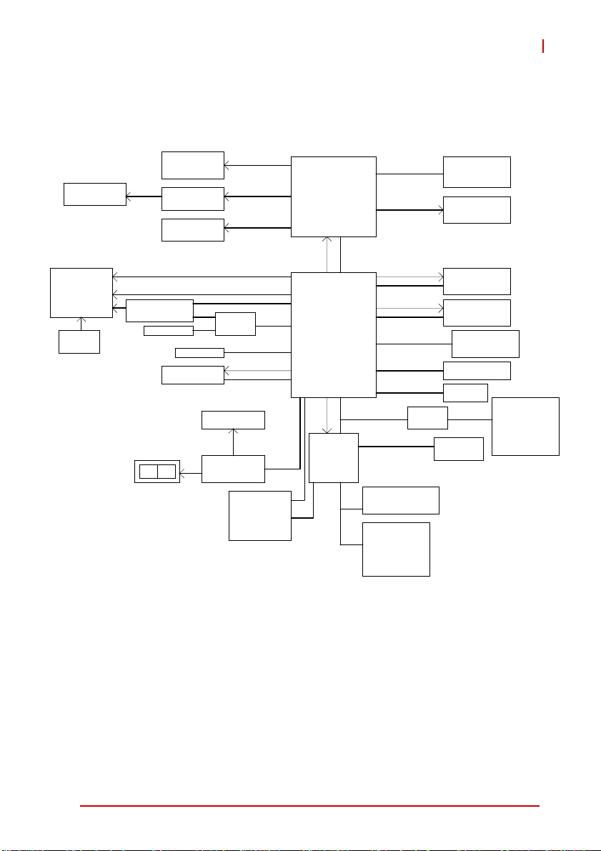
1.5 Block Diagram
IMB-T10
LVDS1
2-ch/24bits
Mini PCIE x1
WLAN
SIM Card
socket
VGA Conn
LVDS
NXP CBTL04083BBS
(SATA Switch)
SATA Port1
Line
MIC
Out
CH7511B
LVDS2
1-ch/24bits
PLTRST#
SATA Port0
PCI x1
USB 2.0 x 1
PCIe x1 Bus
PI2DBS6212ZHE
(SATA Switch)
SATA x1
PCI Bus
Audio Header
Audio Codec
RTL ALC887
GPIO Header
(2x8, 2.0mm Header)
7 GPI
7 GPO
+5V & GND
DDI1
LVDS
SATA x1
PLTRST#
Intel
Atom D2550
Processor
DMI
PLTRST#
INTEL
NM10
LPC Bus
PLTRST#
Super I/O
NUVOTON
NTC6627UD
Channel A
DDI0
PLTRST#
PCIe x1 Bus
PLTRST#
PCIe x1 Bus
USB 2.0
SPI Bus
PCIe x1 Bus
NCT5104D
Rear COM Ports
COM_1(RS232/422/485)
COM_2(RS232)
Internal COM Ports
(2x20, 2.0mm Header)
COM_3(RS232)
COM_4(RS232)
COM_5(RS232)
COM_6(RS232)
DDR3 x1
800 / 1066 MHz
HDMI Conn
Realtek
RTL8111E GLAN1
Realtek
RTL8111E GLAN2
High-Speed USB
Rear x4 port
Header x4 port
AMI SPI 16M ROM
PCIe x 1 slot
PS/2 KB_MS
Header
Internal COM Ports
(2x20, 2.0mm Header)
COM_7(RS232)
COM_8(RS232)
COM_9(RS232)
COM_10(RS232)
Figure 1-1: IMB-T10 Block Diagram
Introduction 5
Page 18

1.6 Functional Description
Processor Support
The IMB-T10 embedded motherboard is equipped with the Intel®
Atom™ Processor D2550 in Micro-FCBGA11 packaging technology. Implemented in 32nm process technology, the Intel® Atom™
D2550 is power-optimized to d eliver robust performance p er watt
for cost-effective embedded applications. Features include:
X 1.86 GHz core speed and 10 watts TDP
X Hyper-Threading Technology
Intel® NM10 Express Chipset
The IMB-T10 is based on the Intel® NM10Express Chipset It provides rich I/O capabilities and flexibility via high-bandwidth interfaces such as PCI Express, PCI, Serial ATA, and Hi-Speed USB
2.0 connectivity, and also provides an Intel® High Definition Audio
interface.
DDR3 memory
To meet the requirements of memory-intensive applications, the
IMB-T10 has a single-channel memory architecture supporting a
DDR3 800/1066 MHz SO-DIMM. The high-bandwidth memory
specification meets the requirements of the latest 3D graphics,
multimedia, and network application, and boosts system performance by eliminating bottlenecks.
Intel® Graphics Media Accelerator GMA 3650
The Intel® Graphics Media Accelerator (GMA) 3650 provides an
integrated 3D graphics engine delivering sophisticated graphics
for large display applications. With support for DirectX 9 hardware
acceleration and 640 MHz display clock The Intel GMA 3650 provides a cost-effective and high-performance graphics solution.
The MB-T10 supports dual independent display technology,
enabling different content to be displayed on two separate display
terminals or a single workspace to be stretched across two display
devices.
6Introduction
Page 19

IMB-T10
Gigabit Ethernet
The IMB-T10 is equipped with the Realtek 8111E PCI Express
GbE controller.
Serial ATA
Storage is efficient and secure with the Serial ATA interface. Utilizing the Intel® NM10, the IMB-T10 support s two Serial ATA devices
capable of reading/writing data at up to 3 Gb/s. The SATA specification improves chassis airflow via thinner and more flexible
cables with lower pin count. One of the two SATA interface is
shared with the mSATA module in Mini PCIe form factor (selected
by jumper).
USB 2.0
The IMB-T10 incorporates the Universal Serial Bus (USB) 2.0
specification that increases peripheral connection speed from 12
Mbps (USB 1.1) to 480 Mbps. USB 2.0 is backward compatible
with USB 1.1.
Hardware Monitoring
A built-in, proactive hardware monitoring system monitors the
CPU temperature, system temperature, and voltage levels to prevent overheating and/or component damage, effect timely failure
detection, and ensure stable supply of current for critical motherboard components.
Watchdog Timer
The watchdog timer (WDT) monitors system operations based on
user-defined configurations. The WDT can be programmed for different time-out periods, such as from 1 to 255 seconds or from 1 to
255 minutes. The WDT generates a reset signal, then a reset
request, after failure to strobe it within the programmed time
period. A register bit may be enabled to indicate if the watchdog
timer caused the reset event. The WDT register is cleared during
the power-on sequence to enable the operating system to take
appropriate action when the watchdog generates a reboot.
Introduction 7
Page 20
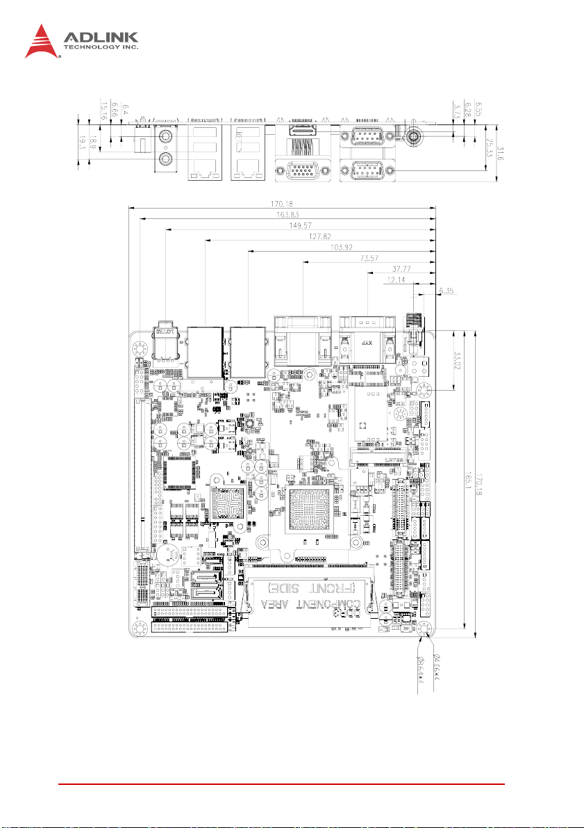
1.7 Mechanical Dimensions
Figure 1-2: IMB-T10 Board Dimensions
8Introduction
Page 21
2 Hardware Information
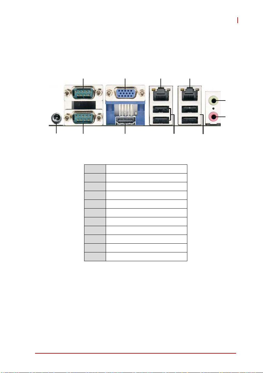
2.1 Rear I/O Layout
IMB-T10
1
2
3
11
10
Figure 2-1: IMB-T10 Rear I/O Layout
1 COM port (COM2)
2 VGA port
3 LAN RJ-45 port
4 LAN RJ-45 port
5 Line-out (green)
6 Mic-in (pink)
7 USB 2.0 Ports (USB23)
8 USB 2.0 Ports (USB01)
9 HDMI port
10 COM port (COM1)
11 DC jack
9
8
4
5
6
7
Hardware Information 9
Page 22

2.2 Rear I/O Connector Pin Definitions
VGA Connector.
Signal Name Pin # Pin # Signal Name
Red 1 2 Green
Blue 3 4 VCC pull-up
GND 5 6 GND
GND 7 8 GND
VCC 9 10 GND
VCC pull-up 11 12 DDC2B DATA
HSYNC 13 14 VSYNC
DDC2B CLK 15
USB Connectors
Pin # Signal Name
1Vcc
2 USB3 USB+
4GND
10 Hardware Information
Page 23

IMB-T10
LAN Port (RJ-45)
This port allows gigabit connection to a Local Area Network (LAN)
using a network hub. The LAN port comes with two LEDs to indicate link, activity and speed. Refer to th e tables b e low f or th e L AN
port pin and LED definitions.
Pin #
1 TX+ BI_DA+
2 TX- BI_DA3 RX+ BI_DB+
4 -- BI_DC+
5-- BI_DC6 RX- BI_DB7 -- BI_DD+
8-- BI_DD-
LED1 (Activity/Link) LED2 (Speed)
Status Description Status Description
Orange Linked Orange 100 Mb connection
Blinking Data Activity Green 1 Gb connection
10BASE-
T/100BASE-TX
Off No Link Off 10 Mb connection
1000BASE-T
LED1
LED2
18
Hardware Information 11
Page 24

COM1/2 Connectors (DB-9)
Pin # RS-232 RS-422* RS-485*
1 DCD-L TX- RTX2RXD TX+ RTX+
3TXD RX+ N/A
4DTR-L RX- N/A
5GND
6DSR-L N/A
7RTS-L N/A
8CTS-L N/A
9RI-L N/A
*RS-422/485 signals supported on COM1 only. See COM1
Mode jumper settings below and 2.3 Board Layout on p. 14 for
NOTE:
NOTE:
J3 location.
COM1 RS-232/422/485 Mode Select (J3)
Pins RS-232 RS-422 RS-485
1-2 Open Shorted Shorted
3-4 Open Shorted Open
5-6 Open Open Shorted
6
1
5
12 Hardware Information
Page 25

IMB-T10
HDMI Connector
Pin # Signal Pin # Signal
1 TMDS Data2+ 2 TMDS Data2 Shield
3 TMDS Data2– 4 TMDS Data1+
5 TMDS Data1 Shield 6 TMDS Data1–
7 TMDS Data0+ 8 TMDS Data0 Shield
9 TMDS Data0– 10 TMDS Clock+
11 TMDS Clock Shield 12 TMDS Clock–
13 CEC 14 Reserved
15 SCL 16 SDA
17 DDC/CEC Ground 18 +5 V Power
19 Hot Plug Detect
Audio Ports
The two-jack audio I/O supports Line-out, and Mic-in functions.
The green Line-out port connects to speakers or headphones,
while the pink Mic-in jack connects to a microphone.
Hardware Information 13
Page 26

2.3 Board Layout
31
30
DC_JACK1
COM1
HDMI1
USB 2.0
T: USB 0
B: USB 1
USB 2.0
T: USB 2
B: USB 3
MI
toB
i
cn
t
o
m
:
S
aep
tnorF
ek
r
AT X 12 V 1
COM2
1
1
VGA1
RJ-45
RJ-45
T:
o
p
1
1
PWR_COM2
PWR_COM1
HD_AUDIO1
1
PANEL1
PLED PWRBT N
HDLED RESET
56
LAN_LED2
1
1
LAN_LED1
AT
AS-inim
2
34
KB_MS1
1
J3
SIM1
ICP-i
n
i/e
m
yr
SOMC
e
tta
B
AUDI O
CODE C
S uper
I/O
1
PCI1
8
7
USB6_7
1
1
1
BLT_PWM1
1
BLT_PWM2
PNL_PWR1
1
PNL_PWR2
10 11 12 13
9
BLT_VOL1
INVERTER1
INVERTER2
1
1
1
CPU_F AN1
USB4_5
1
14
LV DS 2
LV DS 1
SATA_PWR 1 SATA_PWR 2
_
2A
A
ST 2
BIOS
Chip
CHA_F AN1
DDR3_A1
1
_2
A
SAT
15
16
17
18
19
20
21
22
6
CI2
1
BUZZ1
TPM1
DGIO1
1
1
1
1
1
CI1
MSATA_SEL 1
PWR_JP 1
CLRCMOS 1
1
_
_
7MOC0
3
MO
C
11
PCIE1
2729
26
2528
23
24
Figure 2-2: IMB-T10 Board Layout
14 Hardware Information
Page 27

1 ATX 12V Power Connector (Input/Output 10A)
2 COM1 Mode Jumper (J3)
3 Keyboard/Mouse Connector
4 System Panel Header
5 LAN Active LED Header (LAN LED1)
6 LAN Active LED Header (LAN LED2)
7 USB 2.0 Header (USB6_7)
8 BLT_PWM1 & BLT_PWM2, PNL_PWR1 & PNL_PWR2
9 Inverter Connector (Inverter1)
10 Inverter Connector (Inverter2)
11 Backlight Volume Control
12 4-Pin CPU F an Connector (+12V)
13 USB 2.0 Header (USB4_5)
14 LVDS Panel Connector (LVDS1)
15 LVDS Panel Connector (LVDS2)
16 SATA Power Output Connector (SATA_PWR1)
17 SATA Power Output Connector (SATA_PWR2)
18 COM Connector (COM7_10)
19 COM Connector (COM3_6)
20 SATA Connector (SATA2_1)
21 SATA Connector (SATA2_2)
22 4-Pin Chassis Fan Connector (+12V)
23 MSATA_SEL1 Jumper
24 PWR_J P1 Jumper
25 Clear CMOS Header
26 Chas sis Intrusion Headers (CI1, CI2)
27 DGIO1 Header
28 TPM Header
29 Front Panel Audio Header
30 PWR_COM Jumper (PWR_COM1)
31 PWR_COM Jumper (PWR_COM2)
IMB-T10
Table 2-1: Board Layout Legend
Hardware Information 15
Page 28

2.4 Onboard Connector Pin Definitions
LVDS Panel Connector (LVDS1/2)
Pin # Signal Pin # Signal
1 VDD_PWR1 2 +5V
3 VDD_PWR1 4 +5V
5 LBKLT_EN1 6 LBKLT_CTL1
7 GND 8 GND
9 DPLVD_A_DATA1 10 DPL VD_A_DATA0
11 DPLVD_A_DATA1# 12 DPLVD_A_DATA0#
13 GND 14 GND
15 DPL VD_A_DATA3 16 DPLVD_A_DATA2
17 DPLVD_A_DATA3# 18 DPLVD_A_DATA2#
19 GND 20 GND
21 DPL VD_B_DATA1 22 DPLVD_B_DATA0
23 DPLVD_B_DATA1# 24 DPLVD_B_DATA0#
25 GND 26 GND
27 DPL VD_B_DATA3 28 DPLVD_B_DATA2
29 DPLVD_B_DATA3# 30 DPLVD_B_DATA2#
31 GND 32 GND
33 DPLVD_B_CLK 34 DPLVD_A_CLK
35 DPLVD_B_CLK# 36 DPLVD_A_CLK#
37 GND 38 GND
39 +12V 40 +12V
16 Hardware Information
Page 29

SATA Signal Connectors (SATA2_1/2)
Pin # Signal
1 GND
2 TXP
1
3 TXN
4 GND
5 RXN
7
6 RXP
7 GND
SATA Power Output Connectors (SATA_PWR1/2)
IMB-T10
Hardware Information 17
Page 30
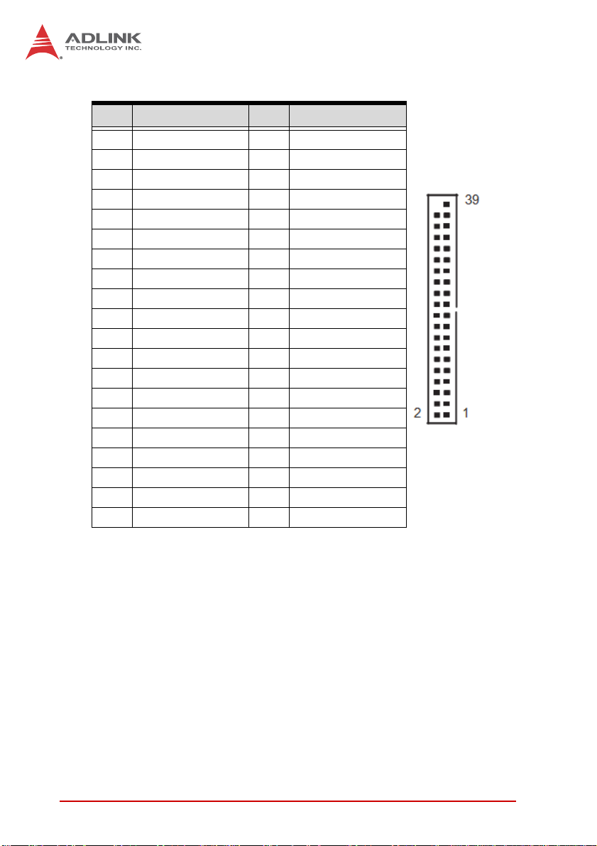
COM3~6 Connector (COM3_6)
Pin # Signal Pin # Signal
1 DDCD#_3 2 DDSR#_3
3 RRXD_3 4 RRTS#_3
5 TTXD_3 6 CCTS#_3
7 DDTR#_3 8 RRI#3
9GND10 X
11 DDCD#_4 12 DDSR#_4
13 RRXD_4 14 RRTS#_4
15 TTXD_4 16 CCTS#_4
17 DDTR#_4 18 RRI#4
19 GND 20 X
21 DDCD#_5 22 DDSR#_5
23 RRXD_5 24 RRTS#_5
25 TTXD_5 26 CCTS#_5
27 DDTR#_5 28 RRI#5
29 GND 30 X
31 DDCD#_6 32 DDSR#_6
33 RRXD_6 34 RRTS#_6
35 TTXD_6 36 CCTS#_6
37 DDTR#_6 38 RRI#6
39 GND
18 Hardware Information
Page 31

COM7~10 Connector (COM7_10)
Pin # Signal Pin # Signal
1 DDCD#_A 2 DDSR#_A
3 RRXD_A 4 RRTS#_A
5 TTXD_A 6 CCTS#_A
7 DDTR#_A 8 RRIXA
9GND10 X
11 DDCD#_B 12 DDSR#_B
13 RRXD_B 14 RRTS#_B
15 TTXD_B 16 CCTS#_B
17 DDTR#_B 18 RRI#B
19 GND 20 X
21 DDCD#_C 22 DDSR#_C
23 RRXD_C 24 RRTS#_C
25 TTXD_C 26 CCTS#_C
27 DDTR#_C 28 RRI#C
29 GND 30 X
31 DDCD#_D 32 DDSR#_D
33 RRXD_D 34 RRTS#_D
35 TTXD_D 36 CCTS#_D
37 DDTR#_D 38 RRI#D
39 GND
IMB-T10
Hardware Information 19
Page 32
CPU/Chassis Fan Connectors (CPU/CHA__FAN1)
Pin # Signal
1GND
2 Fan power (+12V)
3 Fan Tachometer
4 Fan Speed Control
A 3-pin fan connector (no fan speed control) can be connected
to pins 1-3.
NOTE:
NOTE:
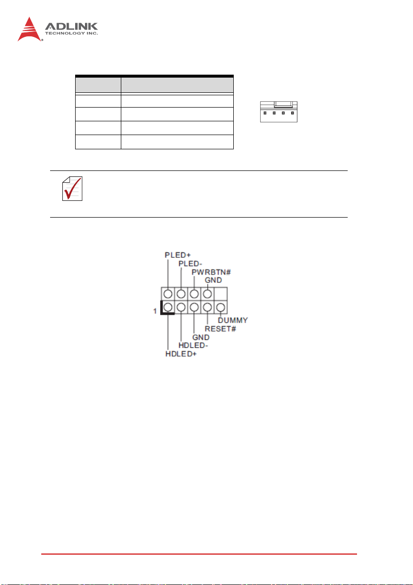
System Panel Header (PANEL1)
14
PWRBTN (Power Switch): Connect to the power switch on the
chassis front panel. You may configure the way to turn off your
system using the power switch.
RESET (Reset Switch): Connect to the reset switch on the chassis
front panel. Press the reset switch to restart the computer if the
computer freezes and fails to perform a normal restart.
PLED (System Power LED): Connect to the power status indicator
on the chassis front panel. The LED is on when the system is
operating. The LED keeps blinking when the system is in S1/S3
sleep state. The LED is off when the system is in S4 sle ep state or
powered off (S5).
20 Hardware Information
Page 33

IMB-T10
HDLED (Hard Drive Activity LED): Connect to the hard drive activity LED on the chassis front panel. The LED is on when the hard
drive is reading or writing data. The front panel design may differ
by chassis. A front panel module mainly consists of power switch,
reset switch, power LED, hard drive activity LED, speaker and etc.
When connecting your chassis front panel module to this header,
make sure the wire assignments and the pin assignments are
matched correctly.
Front Panel Audio Header (HD_AUDIO1)
USB 2.0 Headers (USB4_5, USB6_7)
Pin # Signal Pin # Signal
1+5V2+5V
3 USB0- 4 USB15 USB0+ 6 USB1+
7 GND 8 GND
9 Key 10 NC
Hardware Information 21
Page 34

Chassis Intrusion Headers
Header Status Function
CI1 Close Active case open
CI1 Open Normal
CI2 Close Normal
CI2 Open Active case open
TPM Header (TPM1)
Keyboard/Mouse Connector (KB_MS1)
Pin # Signal
1 KBCLK
2 KBDATA
3MSDATA
4GND
5+5V
6MSLCK
22 Hardware Information
Page 35

ATX 12V Power Connector (ATX12V1)
Pin # Signal
1 GND
2 GND
3 +12V DC
4 +12V DC
2
4
LAN Active LED Headers (LAN LED1/2)
Inverter Connectors (Inverter1/2)
Pin # Signal
1+12V
2+5V
3 LBKLT_EN
4 LBKLT_CTL
5GND
IMB-T10
1
3
Backlight Volume Control (BLT_VOL1)
Pin # Signal
1N/A
2N/A
3 PWRDN
4 LVDS1 BLUP
5 LVDS1 BLDW
6GND
7GND
Hardware Information 23
Page 36

Digital IO Header (DGIO1)
Pin # Signal Pin # Signal
1 Digital Output 0 2 Digital Input 0
3 Digital Output 1 4 Digital Input 1
5 Digital Output 2 6 Digital Input 2
7 Digital Output 3 8 Digital Input 3
9 Digital Output 4 10 Digital Input 4
1 1 Digital Output 5 12 Digital Input 5
13 Digital Output 6 14 Digital Input 6
15 +5V 16 GND
24 Hardware Information
Page 37

IMB-T10
2.5 Jumper Settings
Clear CMOS Header
CLRCMOS1 allows you to clear the data in CMOS. To clear and
reset the system parameters to default setup, please turn off the
computer and unplug the power cord from the power supply. After
waiting for 15 seconds, use a jumper cap to short pin2 and pin3 on
CLRCMOS1 for 5 seconds. However, please do not clear the
CMOS right after you update the BIOS. If you need to clear the
CMOS when you just fi nish updating the BIOS, you must boot up
the system first, and then shut it down before you do the clearCMOS action. Please be noted that the password, date , time, user
default profile and MAC address will be cleared only if the CMOS
battery is removed.
(CLRCMOS1, see p. 14, No. 25)
Pin # Function
1-2 Normal
2-3 Clear CMOS
Backlight PWM
(BLT_PWM1 & BLT_PWM2, see p. 14, No. 8)
Pin # Signal
1-2 +3V
2-3 +5V
Panel Power
(PNL_PWR1 & PNL_PWR2, see p. 14, No. 8)
Pin # Signal
1-2 +3V
2-3 +5V
Hardware Information 25
Page 38
mSATA Mode
(MSATA_SEL1 Jumper, see p. 14, No. 23)
Pin # Function
1-2 Mini-PCIE + SATA2_2
2-3 mSATA (no SATA2_ 2)
ATX/AT Mode Selection
(PWR_JP1, see p. 14, No. 24)
Pin # Function
1-2 AT Mode
2-3 ATX Mode
COM Power
(see p. 14, PWR_COM1: No. 30; PWR_COM2: No. 31)
Pin # Function
1-2 +5V
2-3 Reserved
26 Hardware Information
Page 39

3 Getting Started
The IMB-T10 is a Mini-ITX form factor (6.7" x 6.7", 17.0 x 17.0 cm)
motherboard. Before you install the motherboard, check the configuration of your chassis to ensure that the motherboard fits into
it.
Make sure to unplug the power cord before installing or removing the motherboard. Failure to do so may cause physical inju-
WARNING:
3.1 Screw Holes
Place screws into the holes and tighten to secure the mo therboa rd
to the chassis.
CAUTION:
3.2 Pre-installation Precautions
ries to you and damage to motherboard components.
Do not over-tighten the screws! Doing so may damage the
motherboard.
IMB-T10
Take note of the following precautions before you install motherboard components or change any motherboard settings.
1. Unplug the power cord from the wall socket before
touching any component.
2. To avoid damaging the motherboard components due to
static electricity, always use a grounded wrist strap.
3. Hold component s by the edges a nd do not touch the ICs.
4. Whenever you uninstall any component, place it on a
grounded antistatic pad or in the ba g that comes with the
component.
Before you install or remove any component, ensure that the
power is switched off or the power cord is detached from the
WARNING:
Getting Started 27
power supply. Failure to do so may cause severe damage to
the motherboard, peripherals, and/or components.
Page 40

3.3 Installation of Memory Modules (SO-DIMM)
This motherboard provides one 204-pin DDR3 (Double Data Rate
3) SO-DIMM slot.
Step 1. Align a DIMM on the slot su ch that the notch on the DIMM
matches the break on the slot.
The DIMM only fits in one orientation. Forcing the DIMM into
the slot It will cause permanent damage to the motherboard
WARNING:
Step 2. Firmly insert the DIMM into the slot until the retaining clips
at both ends fully snap back in place and the DIMM is properly
seated.
and the DIMM.
3.4 Expansion Slots (PCI, PCI Express and Mini-PCIe/mSATA)
This motherboard has 1 PCI slot, 1 PCI Express slot, and 1
Mini-PCIe/mSATA slot.
PCI slot: PCI slot is used to install expansion cards that have the
32-bit PCI interface.
PCIE slot: PCIE1 (PCIE x1 slot) is used for PCI Express x1 lane
width graphics cards.
Mini-PCIe/mSATA slot: MINI_PCIE1 (Mini-PCIe/mSATA slot; full
size) is used for PCI Ex- press mini cards or mSATA cards.
28 Getting Started
Page 41

IMB-T10
Installing an expansion card
Step 1. Before installing the expansion card, please make sure
that the power supply is switched off or the power cord is
unplugged. Please read the documentation of the expansion card
and make necessary hardware settings for the card before you
start the installation.
Step 2. Remove the system unit cover (if your motherboard is
already installed in a chassis).
Step 3. Remove the bracket facing the slot that you intend to use.
Keep the screws for later use.
Step 4. Align the card connector with the slot and press firmly until
the card is completely seated on the slot.
Step 5. Fasten the card to the chassis with screws.
Step 6. Replace the system cover.
3.5 Driver Installation
The IMB-T10 drivers for Windows 7 32-bit are located in the following files that can be downloaded from the ADLINK website
(http://www.adlinktech.com):
Chipset \1.Chipset\Intel\(v9.2.2.1034)\
Display \2.VGA\Win7_32\(v8.0.0.6.1082)\
Audio \3.Audio\6937_PG367_Win8_Win7_Vista_XP_WHQLed\
LAN \4.LAN\WIN7\Install_Win7_7069_03212013\
COM \5.COM\
Follow the instructions below to install the required IMB-T10 drivers:
1. Install the Windows operating system before installing any
driver. Most standard I/O device drivers are installed during
Windows installation.
2. Insta ll the Chipset driver by running the program \1.Chip-
set\Intel\(v9.2.2.1034)\setup.exe. Follow the instructions
given and reboot when instructed.
Getting Started 29
Page 42

3. Install the Display driver and utilities by running the program
\2.VGA\Win7_32\(v8.0.0.6.1082)\setup.exe. Follow the
instructions given and reboot when instructed.
4. Install the Audio driver by running the program \3.Audio\
6937_PG367_Win8_Win7_Vista_XP_WHQLed\setup.exe.
Follow the instructions given and reboot if required.
5. Install the LAN driver by running the program \4.LAN\
WIN7\Install_Win7_7069_03212013\LAN\Win7\setup.exe.
Follow the instructions given and reboot if required.
6. Install the COM driver by running the program
\5.COM\NuvSerial v1.0.2011.1109 (WHQL).exe. Follow the instructions given and reboot if required.
30 Getting Started
Page 43

4 BIOS Setup
4.1 Introduction
This section explains how to use the UEFI SETUP UTILITY to
configure your system. The UEFI chip on the motherboard stores
the UEFI SETUP UTILITY. You may run the UEFI SETUP UTILITY
when you start the computer. Please press <F2> or <Del> during
the Power-On-Self-Test (POST) to enter the UEFI SETUP UTILITY, otherwise POST will continue with its test routines.
If you wish to enter the UEFI SETUP UTILITY after POST, restart
the system by pressing <Ctl> + <Alt> + <Delete> , or by pressing
the reset button on the system chassis. You may also restart by
turning the system off and then back on.
Because the UEFI software is constantly being updated, the
following UEFI setup screens and descriptions are for refer-
NOTE:
NOTE:
4.1.1 UEFI Menu Bar
ence purpose only, and they may not exactly match what you
see on your screen.
IMB-T10
The top of the screen has a menu bar with the following selections:
Main: To set up the system time/date information
Advanced: To set up the advanced UEFI features
H/W Monitor: To display current hardware status
Boot: To set up the default system device to locate and load the
Operating System
Security: To set up the security features
Exit: To exit the current screen or the UEFI SETUP UTILITY
Use <←> key or <→> key to choose between the selections on
the menu bar, and then press <Enter> to get into the sub screen.
You can also use the mouse to choose your require d item by clicking.
BIOS Setup 31
Page 44

4.1.2 Navigation Keys
The following table describes the functions of each navigation key.
Navigation key(s) Functional Description
←/→
↑/↓
+/- Choose between options of the selected item
<Enter> Bring up the selected screen
<F1> Display the General Help Screen
<F7> Discard changes
<F9> Load optimal default values for all settings
<F10> Save changes and exit the UEFI SETUP UTILITY
<F12> Print screen
<ESC> Jump to the Exit Screen or exit the current screen
Moves cursor left or right to select Screens
Moves cursor up or down to select items
32 BIOS Setup
Page 45

IMB-T10
4.2 Main Screen
When you enter the UEFI SETUP UTILITY, the Main screen will
appear and display the system overview.
BIOS Setup 33
Page 46

4.3 Advanced Screen
In this section, you may set the configurations for the following
items: CPU Configuration, Chipset Configuration, Storage Configuration, Super IO Configuration, ACPI Configuration and USB
Configuration.
Setting incorrect values in this section may cause the system
to malfunction.
WARNING:
Instant Flash
Instant Flash is a UEFI flash utility embedded in Flash ROM. This
convenient UEFI update tool allows you to update system UEFI
without entering operating systems such as MS-DOS or Windows®. Simply launch this tool and save the new UEFI file to your
USB flash drive, floppy disk, or hard drive, then update your UEFI
in a few clicks without preparing an additional floppy diskette or a
complicated flash utility. Please note that the USB flash drive or
hard drive must use the FAT32/16/12 file system. If you execute
34 BIOS Setup
Page 47

IMB-T10
the Instant Flash utility, the utility will show the UEFI files and their
respective information. Select the proper UEFI file to update your
UEFI, and reboot your system after the UEFI update process completes.
BIOS Setup 35
Page 48

4.3.1 CPU Configuration
Intel Hyper-Threading Technology
Enabling this feature requires a computer system with an Intel processor that supports Hyper-Threading technology and an operating system that includes optimization for this technology, such as
Microsoft® Windows® 7. Set to [Enabled] if using Microsoft® Windows® 7.
No-Execute Memory Protection
No-Execution (NX) Memory Protection Technology is an enhancement to the IA-32 Intel Architecture. An IA-32 processor with “No
Execute (NX) Memory Protection” can prevent malicious software
using data pages to execute code.
36 BIOS Setup
Page 49

4.3.2 CPU Configuration
LVDS1 Panel Type Selection
IMB-T10
Use this to select LVDS1 panel type. The default value is
[1366x768/18- bit/1-ch/LED].
LVDS2 Panel Type Selection
Use this to select LVDS2 panel type. The default value is
[1366x768/18- bit/1-ch/LED].
Primary Graphics Adapter
This allows you to select the boot graphic adapter priority. The
default value is [VBIOS Default].
ACPI HPET Table
Use this option to enable or disable ACPI HPET Table. The default
value is [Enabled]. Please set this option to [Enabled] if you plan to
use this motherboard to submit Windows® certification.
BIOS Setup 37
Page 50

Restore on AC/Power Loss
This allows you to set the power state after an unexpected AC/
power loss. If [Power Off] is selected, the AC/power remains off
when the power recovers. If [Power On] is selected, the AC/power
resumes and the system starts to boot up when the power recovers.
Onboard HD Audio
Select [Auto], [Enabled] or [Disabled] for the onboard HD Audio
feature. If you select [Auto], the onboard HD Audio will be disabled
when PCI Sound Card is plugged.
Front Panel
Select [Auto] or [Disabled] for the onboard HD Audio Front Panel.
Onboard LAN1
This allows you to enable or disable the “Onboard LAN1 ” feat ur e.
Onboard LAN2
This allows you to enable or disable the “Onboard LAN2 ” feat ur e.
38 BIOS Setup
Page 51

4.3.3 Storage Configuration
SATA Mode
IMB-T10
Use this to select SATA mode. Configuration options: [IDE Mode],
[AHCI Mode] and [Disabled]. The default value is [IDE Mode].
AHCI (Advanced Host Controller Interface), supports NCQ and
other new features that will improve SATA disk performance,
NOTE:
NOTE:
but IDE mode does not have these advantages.
Hard Disk S.M.A.R.T.
Use this option to enable or disable the S.M.A.R.T. (Self-Monitoring, Analysis, and Reporting Technology) feature. Configuration
options: [Disabled] and [Enabled].
BIOS Setup 39
Page 52

4.3.4 Super IO Configuration
COM1~10 Configuration
Use this to set parameters of COM1~10.
WDT Timeout Reset
This allows users to enable/disable the Watch Dog Timer timeout
to reset system. The default value is [Disabled].
40 BIOS Setup
Page 53

4.3.5 ACPI Configuration
Suspend to RAM
IMB-T10
Use this option to select whether to auto-detect or disable the Suspend-to- RAM feature. Select [Auto] will enable this feature if the
OS supports it.
S3 Video Repost
Use this to enable/disable S3 Video Repost. The default value is
[Enabled].
Check Ready Bit
Use this option to enable or disable the feature Check Ready Bit.
PS/2 Keyboard Power On
Use this option to enable or disable PS/2 keyboard to turn on the
system from the power-soft-off mode.
BIOS Setup 41
Page 54

PCI Devices Power On
Use this option to enable or disable PCI devices to turn on the system from the power-soft-off mode.
RTC Alarm Power On
Use this option to enable or disable RTC (Real Time Clock) to
power on the system.
USB Keyboard/Remote Power On
Use this option to enable or disable USB Keyboard/Remote to
power on the system.
USB Mouse Power On
Use this option to enable or disable USB Mouse to power on the
system.
42 BIOS Setup
Page 55

4.3.6 USB Configuration
USB 2.0 Controller
IMB-T10
Use this option to enable or disable the use of USB 2.0 controller.
Legacy USB Support
Use this option to select legacy support for USB devices. There
are four configuration options: [Enabled], [Auto], [Disabled] and
[UEFI Setup Only]. The default value is [Enabl ed]. Please refer t o
the following descriptions for details of these four options:
X [Enabled] - Enables support for legacy USB.
X [Auto] - Enables legacy support if USB devices are con-
nected.
X [Disabled] - USB devices are not allowed to use under leg-
acy OS and UEFI setup when [Disabled] is selected. If you
experience USB compatibility issues, it is recommended to
select [Disabled] to enter OS.
X [UEFI Setup Only] - USB devices are allowed to use only
under UEFI setup and Windows / Linux OS.
BIOS Setup 43
Page 56

4.4 Hardware Health Event Monitoring System
This section of the BIOS settings allows you to monitor the status
of the hardware on your system, including the parameters of the
CPU temperature, motherboard temperature, CPU fan speed,
chassis fan speed, and critical voltage.
CPU_FAN1 Setting
This allows you to set the CPU fan (CPU_FAN1) speed. Configuration options: [Full On] and [Automatic Mode]. The default value
is [Full On].
CHA_FAN1 Setting
This allows you to set chassis fan (CHA_FAN1) speed. Configuration options: [Full On] and [Automatic Mode]. The default value is
[Full On].
44 BIOS Setup
Page 57

IMB-T10
Case Open Feature
This allows you to enable or disable case open detection feature.
The default value is [Disabled].
Clear Status
This option appears only when the the system detects that the
case has been opened. Use this option to keep or clear the record
of previous chassis intrusions.
BIOS Setup 45
Page 58

4.5 Boot Screen
This section of the BIOS settings displays the availabl e devi ces o n
your system for configuring the boot settings and boot priority.
Setup Prompt Timeout
This shows the number of seconds to wait for the setup activation
key; 65535(0XFFFF) means waiting indefinitely.
Bootup Num-Lock
If this item is set to [On], it will automatically activate the Numeric
Lock function after boot-up.
Full Screen Logo
Use this option to enable or disable OEM Logo. The default value
is [Disabled].
Boot From Onboard LAN
Use this option to enable or disable the Boot From Onboard LAN
feature.
46 BIOS Setup
Page 59

IMB-T10
4.6 Security Screen
This section of the BIOS settings en ables you to set, change or
clear the supervisor/user password for the system.
BIOS Setup 47
Page 60
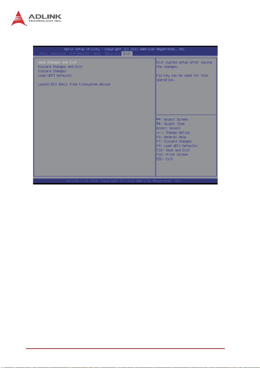
4.7 Exit Screen
Save Changes and Exit
Selecting this option will display the message “Save configuration
changes and exit setup?” Select [OK] to save the changes and exit
the UEFI SETUP UTILITY.
Discard Changes and Exit
Selecting this option will display the message “Discard changes
and exit setup?” Select [OK] to exit the UEFI SETUP UTILITY
without saving any changes.
Discard Changes
Selecting this option will display the message “Discard changes?”
Select [OK] to discard all changes.
48 BIOS Setup
Page 61

IMB-T10
Load UEFI Defaults
Load UEFI default values for all the setup questions . F9 key can
be used for this operation.
Launch EFI Shell from file system device
Attempts to Launch EFI Shell application (Shell64.efi) from one of
the available file system devices.
BIOS Setup 49
Page 62

This page intentionally left blank.
50 BIOS Setup
Page 63

Appendix A - WDT Sample Code
#include "AsrCore.h"
#include "AsrError.h"
#include <tchar.h>
#include <stdio.h>
#pragma comment(lib, "AsrCore.lib")
void DisplayError(int ErrorCode);
void ShowError(bool bSuccess);
int main(void)
{
DWORD major, minor, release, build;
AsrLibDllGetVersion(&major, &minor, &release, &build);
_tprintf(_T("DLL Version [%d.%d.%d.%d]\n"), major, minor,
release, build);
IMB-T10
bool bSuccess = false;
ShowError(bSuccess =
AsrLibDllInit()); if
(bSuccess)
{
DWORD size = 0;
ShowError(bSuccess =
AsrLibGetBIOSVersion(NULL, &size)); TCHAR*
BIOSVersion = new TCHAR[size + 1];
ShowError(bSuccess =
AsrLibGetBIOSVersion(BIOSVersion, &size));
if (bSuccess)
_tprintf(_T("BIOS Version [%s]\n"),BIOSVersion);
WDT Sample Code 51
Page 64

delete BIOSVersion;
BIOSVersion = NULL;
size = 0;
ShowError(bSuccess =
AsrLibGetPlatformName(NULL, &size)); TCHAR*
PlatformName = new TCHAR[size + 1];
ShowError(bSuccess =
AsrLibGetPlatformName(PlatformName, &size));
if (bSuccess)
_tprintf(_T("Platform [%s]\n"), PlatformName);
delete PlatformName;
PlatformName = NULL;
_tprintf(_T("Enable WDT timeout in 60
second...\n")); AsrLibWDSetConfig(60);
_tprintf(_T("Press any key to reset WDT\n"));
AsrLibWDTrigger();
_tprintf(_T("Press any key to disable WDT\n"));
system("PAUSE");
AsrLibWDDisable();
}
AsrLibDllUnInit();
return 0;
}
void DisplayError(int ErrorCode)
{
_tprintf(_T("(0x%04X) "), ErrorCode);
switch(ErrorCode)
{
case ERRLIB_SUCCESS :
_tprintf(_T("ERRLIB_SUCCESS\n"));
52 WDT Sample Code
Page 65

break;
case ERRLIB_DLL_NOT_INIT :
_tprintf(_T("ERRLIB_DLL_NOT_INIT\n"));
break;
case ERRLIB_PLATFORM_UNSUPPORT :
_tprintf(_T("ERRLIB_PLATFORM_UNSUPPORT\n"));
break;
case ERRLIB_API_UNSUPPORT :
_tprintf(_T("ERRLIB_API_UNSUPPORT\n"));
break;
case ERRLIB_API_CURRENT_UNSUPPORT :
_tprintf(_T("ERRLIB_API_CURRENT_UNSUPPORT\n"));
IMB-T10
break;
case ERRLIB_LIB_INIT_FAIL :
_tprintf(_T("ERRLIB_LIB_INIT_FAIL\n"));
break;
case ERRLIB_INVALID_PARAMETER :
_tprintf(_T("ERRLIB_INVALID_PARAMETER\n"));
break;
case ERRLIB_INVALID_ID :
_tprintf(_T("ERRLIB_INVALID_ID\n"));
WDT Sample Code 53
Page 66

break;
case ERRLIB_OUTBUF_RETURN_SIZE_INCORRECT :
_tprintf(_T("ERRLIB_OUTBUF_RETURN_SIZE_INCORRECT\n")
);
break;
case ERRLIB_ARRAY_LENGTH_INSUFFICIENT :
_tprintf(_T("ERRLIB_ARRAY_LENGTH_INSUFFICIENT\n"));
break;
case ERRLIB_THREAD_LOCKED :
_tprintf(_T("ERRLIB_THREAD_LOCKED\n"));
break;
case ERRLIB_LIB_INVALID_VERSION :
_tprintf(_T("ERRLIB_LIB_INVALID_VERSION\n"));
break;
default :
tprintf(_T("UNKNOWN_ERROR\n"));
}
}
void ShowError(bool bSuccess)
{
if (!bSuccess)
{
DisplayError(AsrLibDllGetLastError())
}
}
54 WDT Sample Code
Page 67

IMB-T10
Important Safety Instructions
For user safety, please read and follow all instructions,
WARNINGS, CAUTIONS, and NOTES marked in this manual and
on the associated equipment before handling/operating the
equipment.
X Read these safety instructions carefully.
X Keep this user’s manual for future reference.
X Read the specifications section of this manual for detailed
information on the operating environment of this equipment.
X When installing/mounting or uninstalling/removing
equipment:
Z Turn off power and u nplug any power cords/cables.
X To avoid electrical shock and/or dam age to equipment:
Z Keep equipment away from water or liquid sources;
Z Keep equipment away from high heat or high humidity;
Z Keep equipment properly ventilated (do not block or
cover ventilation openings);
Z Make sure to use recommended voltage and powe r
source settings;
Z Always install and operate equipment near an easily
accessible electrical socket-outlet;
Z Secure the power cord (do not place any obje ct on /ove r
the power cord);
Z Only install/attach and operate equipment on stable
surfaces and/or recommended mountings; and,
Z If the equipment will not be used for long periods of time,
turn off and unplug the equipment from its power source.
Important Safety Instructions 55
Page 68

X Never attempt to fix the equipment. Equipmen t sho u ld on ly
be serviced by qualified personnel.
A Lithium-type battery may be provided for uninterrupted, backup
or emergency power.
Risk of explosion if battery is replaced with one of an incorrect
WARNING:
type. Dispose of used batteries appropriately.
X Equipment must be serviced by authorized technicians
when:
Z The power cord or plug is damaged;
Z Liquid has penetrated the equipment;
Z It has been exposed to high humidity/moisture;
Z It is not functioning or does not function according to the
user’s manual;
Z It has been dropped and/or damaged; and/or,
Z It has an obvious sign of breakage.
56 Important Safety Instructions
Page 69

Getting Service
Contact us should you require any service or assistance.
ADLINK Technology, Inc.
Address: 9F, No.166 Jian Yi Road, Zhonghe District
New Taipei City 235, Taiwan
ᄅקؑխࡉ৬ԫሁ 166 ᇆ 9 ᑔ
Tel: +886-2-8226-5877
Fax: +886-2-8226-5717
Email: service@adlinktech.com
Ampro ADLINK Technology, Inc.
Address: 5215 Hellyer Avenue, #110, San Jose, CA 95138, USA
Tel: +1-408-360-0200
Toll Free: +1-800-966-5200 (USA only)
Fax: +1-408-360-0222
Email: info@adlinktech.com
ADLINK Technology (China) Co., Ltd.
Address: Ϟ⍋Ꮦ⌺ϰᮄᓴ∳催⾥ᡔು㢇䏃 300 ো(201203)
300 Fang Chun Rd., Zhangjiang Hi-Tech Park,
Pudong New Area, Shanghai, 201203 China
Tel: +86-21-5132-8988
Fax: +86-21-5132-3588
Email: market@adlinktech.com
IMB-T10
ADLINK Technology Beijing
Address: ࣫ҀᏖ⍋⎔Ϟഄϰ䏃 1 োⲜ߯ࡼ E ᑻ 801 ᅸ(100085)
Tel: +86-10-5885-8666
Fax: +86-10-5885-8626
Email: market@adlinktech.com
ADLINK Technology Shenzhen
Address: ⏅ഇᏖቅ⾥ᡔು催ᮄϗ䘧᭄ᄫᡔᴃು
Tel: +86-755-2643-4858
Fax: +86-755-2664-6353
Email: market@adlinktech.com
LiPPERT ADLINK Technology GmbH
Address: Hans-Thoma-Strasse 11, D-68163, Mannheim, Germany
Tel: +49-621-43214-0
Fax: +49-621 43214-30
Email: emea@adlinktech.com
Rm. 801, Power Creative E, No. 1,
Shang Di East Rd., Beijing, 100085 China
A1 2 ὐ C (518057)
2F, C Block, Bldg. A1, Cyber-Tech Zone, Gao Xin Ave. Sec. 7,
High-Tech Industrial Park S., Shenzhen, 518054 China
Getting Service 57
Page 70

ADLINK Technology, Inc. (French Liaison Office)
Address: 15 rue Emile Baudot, 91300 Massy CEDEX, France
Tel: +33 (0) 1 60 12 35 66
Fax: +33 (0) 1 60 12 35 66
Email: france@adlinktech.com
ADLINK Technology Japan Corporation
Address: ͱ101-0045 ᵅҀ䛑ҷ⬄⼲⬄䤯ފ⬎ 3-7-4
Tel: +81-3-4455-3722
Fax: +81-3-5209-6013
Email: japan@adlinktech.com
ADLINK Technology, Inc. (Korean Liaison Office)
Address: 137-881 昢殾柢 昢爎割 昢爎堆嵢 326, 802 (昢爎壟, 微汾瘶捒娯)
Tel: +82-2-2057-0565
Fax: +82-2-2057-0563
Email: korea@adlinktech.com
ADLINK Technology Singapore Pte. Ltd.
Address: 84 Genting Lane #07-02A, Cityneon Design Centre,
Tel: +65-6844-2261
Fax: +65-6844-2263
Email: singapore@adlinktech.com
ADLINK Technology Singapore Pte. Ltd. (Indian Liaison Office)
Address: #50-56, First Floor, Spearhead Towers
Malleswaram, Bangalore - 560 055, India
Tel: +91-80-65605817, +91-80-42246107
Fax: +91-80-23464606
Email: india@adlinktech.com
⼲⬄ 374 ɛɳ 4F
KANDA374 Bldg. 4F, 3-7-4 Kanda Kajicho,
Chiyoda-ku, Tokyo 101-0045, Japan
802, Mointer B/D, 326 Seocho-daero, Seocho-Gu,
Seoul 137-070, Korea
Singapore 349584
Margosa Main Road (between 16th/17th Cross),
ADLINK Technology, Inc. (Israeli Liaison Office)
Address: 6 Hasadna St., Kfar Saba 44424, Israel
Tel: +972-9-7446541
Fax: +972-9-7446542
Email: israel@adlinktech.com
58 Getting Service
 Loading...