

Page 1

IMB-S90 IPMI
AMI MegaRAC SP-X Firmware
User's Manual
Manual Revision: 1.00
Revision Date: November 22, 2013
Part Number: 50-1X007-1000
Advance Technologies; Automate the World.
Page 2

Revision History
IMB-S90 IPMI User’s Manual
Rev Date Description
1.00 22/11/2013 Initial release
2
Page 3

IMB-S90 IPMI User’s Manual
Preface
Copyright 2013 ADLINK Technology, Inc.
This document contains proprietary information protected by copyright. All rights are
reserved. No part of this manual may be reproduced by any mechanical, electronic, or
other means in any form without prior written permission of the manufacturer.
This document is adapted from the AMI MegaRAC® SP-X User's Guide, Version 5.3, with
full permission from AMI. All content is also subject to the copyright of the original
document.
Disclaimer
The information in this document is subject to change without prior notice in order to
improve reliability, design, and function and does not represent a commitment on the part
of the manufacturer. In no event will the manufacturer be liable for direct, indirect, special,
incidental, or consequential damages arising out of the use or inability to use the product
or documentation, even if advised of the possibility of such damages.
Environmental Responsibility
ADLINK is committed to fulfill its social responsibility to global environmental preservation
through compliance with the European Union's Restriction of Hazardous Substances
(RoHS) directive and Waste Electrical and Electronic Equipment (WEEE) directive.
Environmental protection is a top priority for ADLINK. We have enforced measures to
ensure that our products, manufacturing processes, components, and raw materials have
as little impact on the environment as possible. When products are at their end of life, our
customers are encouraged to dispose of them in accordance with the product disposal
and/or recovery programs prescribed by their nation or company.
Trademarks
Product names mentioned herein are used for identification purposes only and may be
trademarks and/or registered trademarks of their respective companies.
3
Page 4

IMB-S90 IPMI User’s Manual
Table of Contents
1 Introduction.............................................................................................8
1.1 Notes......................................................................................................................8
2 SP-X Features .........................................................................................9
2.1 IPMI Message Interface Support ............................................................................9
2.2 Media Redirection...................................................................................................9
2.3 IPMI 2.0 based management..................................................................................9
2.4 Event Log and Alerting ...........................................................................................9
2.5 Sophisticated User Management............................................................................9
2.6 LDAP support .........................................................................................................9
2.7 Remote Server Power Control..............................................................................10
2.8 SSH based SOL ...................................................................................................10
2.9 Web based configuration......................................................................................10
2.10 KVM/Media Redirection Support...........................................................................10
2.11 Security Support...................................................................................................11
2.12 Multiple Language Support for Web and KVM......................................................11
2.13 Miscellaneous.......................................................................................................11
3 SP-X Web GUI .......................................................................................12
3.1 MegaRAC® GUI Overview...................................................................................12
3.1.1 Supported Browsers.................................................................................................. 12
3.1.2 Supported OS............................................................................................................ 12
3.2 User Name and Password....................................................................................14
3.2.1 Required Browser Settings:....................................................................................... 14
3.2.2 Default User Name and Password............................................................................ 15
3.3 Using MegaRAC SP-X..........................................................................................15
3.3.1 Menu Bar...................................................................................................................15
3.3.2 Quick Button and Logged-in User............................................................................. 16
3.3.3 Logged-in user and its privilege level........................................................................ 16
4
Page 5

IMB-S90 IPMI User’s Manual
3.4 Dashboard............................................................................................................17
3.4.1 Device Information .................................................................................................... 17
3.4.2 Network Information.................................................................................................. 17
3.4.3 Remote Control......................................................................................................... 18
3.4.4 Sensor Monitoring..................................................................................................... 18
3.4.5 Event Logs ................................................................................................................ 18
3.5 Field Replaceable Unit (FRU)...............................................................................18
3.5.1 Basic Information....................................................................................................... 19
3.5.2 Chassis Information................................................................................................... 19
3.5.3 Board Information...................................................................................................... 20
3.5.4 Product Information................................................................................................... 20
3.6 Server Health Group.............................................................................................20
3.6.1 Sensor Readings....................................................................................................... 21
3.6.2 Event Log..................................................................................................................23
3.6.3 System & Audit logs.................................................................................................. 25
3.6.4 Blue Screen of Death................................................................................................ 26
3.7 Configuration Group .............................................................................................27
3.7.1 Active Directory......................................................................................................... 27
3.7.2 DNS...........................................................................................................................31
3.7.3 System Event Log..................................................................................................... 34
3.7.4 Images Redirection ................................................................................................... 35
3.7.5 LDAP/E-Directory Settings........................................................................................ 39
3.7.6 License...................................................................................................................... 43
3.7.7 Mouse Mode.............................................................................................................. 44
3.7.8 NCSI..........................................................................................................................45
3.7.9 Network.....................................................................................................................46
3.7.10 Network Link.............................................................................................................. 48
3.7.11 Procedure:.................................................................................................................49
3.7.12 NTP Settings............................................................................................................. 49
5
Page 6

IMB-S90 IPMI User’s Manual
3.7.13 PAM Ordering............................................................................................................ 51
3.7.14 PEF ........................................................................................................................... 51
3.7.15 RADIUS.....................................................................................................................62
3.7.16 Remote Session........................................................................................................ 64
3.7.17 Services..................................................................................................................... 65
3.7.18 SMTP ........................................................................................................................ 68
3.7.19 SSL............................................................................................................................ 70
3.7.20 System and Audit Log............................................................................................... 75
3.7.21 System Firewall......................................................................................................... 77
3.7.22 Virtual Media ............................................................................................................. 85
3.8 Remote Control.....................................................................................................86
3.8.1 Console Redirection.................................................................................................. 86
3.8.2 Server Power Control................................................................................................ 98
3.8.3 Java SOL................................................................................................................... 99
3.9 Auto Video Recording.........................................................................................101
3.9.1 Triggers Configuration.............................................................................................102
3.9.2 Video Recording...................................................................................................... 103
3.10 Maintenance Group............................................................................................105
3.10.1 Preserve Configuration............................................................................................ 105
3.10.2 Restore Configuration ............................................................................................. 110
3.10.3 System Administrator .............................................................................................. 111
3.11 Firmware Update................................................................................................112
3.11.1 Firmware Update..................................................................................................... 113
3.11.2 Image Transfer Protocol.......................................................................................... 116
3.12 Log Out...............................................................................................................117
3.13 Stand Alone Application......................................................................................117
3.13.1 Launching from Windows........................................................................................ 117
3.13.2 Launching from Linux.............................................................................................. 118
3.13.3 Launching from GUI based environment................................................................. 120
6
Page 7

IMB-S90 IPMI User’s Manual
3.14 FLASH Tools ......................................................................................................121
3.15 YAFUFlash .........................................................................................................121
3.15.1 Installation in Windows............................................................................................ 121
3.15.2 Installation in Linux.................................................................................................. 127
3.15.3 Installation in DOS................................................................................................... 135
3.16 EFI base YAFUKCS ...........................................................................................138
3.16.1 Installation...............................................................................................................138
3.16.2 YAFU Error Codes .................................................................................................. 138
3.17 VMCLI Tool.........................................................................................................139
3.17.1 VMCLI (Virtual Media Command Line Interface):.................................................... 139
3.17.2 Installation in Windows............................................................................................ 139
3.17.3 Installation in Linux.................................................................................................. 143
3.18 SOL ....................................................................................................................148
Appendix A...............................................................................................149
A.1 Ports Usage........................................................................................................149
A.2 Mouse Mode.......................................................................................................150
A.3 KVM Sharing Scenario .......................................................................................151
A.3.1 Scenario 1:..............................................................................................................151
A.3.2 Scenario 2:..............................................................................................................151
A.3.3 Scenario 3:..............................................................................................................151
A.4 Default IPMI Channel Numbers..........................................................................151
A.5 IPMI Commands Supported by SP-X Firmware..................................................152
A.5.1 Applications commands .......................................................................................... 152
A.5.2 Bridge commands ................................................................................................... 158
A.5.3 Storage Commands ................................................................................................ 165
A.5.4 Transport Commands.............................................................................................. 167
A.5.5 AMI Commands....................................................................................................... 175
A.5.6 APML Commands................................................................................................... 187
Getting Service...........................................................................................191
7
Page 8

IMB-S90 IPMI User’s Manual
1 Introduction
1.1 Notes
This document describes the operation of AMI’s MegaRAC SP-X firmware adapted for the
ADLINK IMB-S90.
“Generic MegaRAC® SP-X core” refers to the new core of AMI’s MegaRAC® SP firmware
running on various SoC platforms.
“SP” and “Service Processor” terms are used interchangeably throughout this document to
refer to AMI’s generic MegaRAC® SP solution.
“MegaRAC® SP-X”, “MegaRAC SP”, “SP-X”, “SP-X Core” and “Generic MegaRAC® SP”
terms are used interchangeably throughout this document to refer to AMI’s service
processor firmware solution.
8
Page 9

IMB-S90 IPMI User’s Manual
2 SP-X Features
2.1 IPMI Message Interface Support
• KCS (System Interface Support)
• LAN
• USB
2.2 Media Redirection
• Simultaneous floppy, Hard disk or USB and CD or DVD redirection.
• Efficient USB 2.0 based CD/DVD redirection with a typical speed of 20XCD.
• Support for USB key
• Completely secured (Authenticated or Encrypted) remote KVM or vMedia.
2.3 IPMI 2.0 based management
• BMC stack with a full IPMI 2.0 implementation
• Customizable sensor management
• IPMI threads management
• Support for reusing the space upon a SEL entry deletion
• LAN channel mapping via MDS. Support for Setting Override using PDK hook
2.4 Event Log and Alerting
• Read Log events
• Sensor readings
• SNMP traps
• E-mail alerts
2.5 Sophisticated User Management
• IPMI based user management
• Added security with SSL (HTTPS)
• Multiple user permission level
• Multiple user profiles
2.6 LDAP support
9
Page 10

IMB-S90 IPMI User’s Manual
• Direct LDAP support from the device
• Open LDAP (Generic LDAP) supported
2.7 Remote Server Power Control
• Server’s power status report
• Support for remotely power-cycle, power-down, power-up and reset the server
2.8 SSH based SOL
• Power control of the server
• Support for all DMTF Profiles
• Complete command support
• Customizable parser for easy update to future modifications in grammar
• Dynamic target discovery
• Firmware update
• Role based authentication and authorization
• Output filtering
• OEM command and target
2.9 Web based configuration
• Full configuration using web UI
• Fail-safe firmware upgrade
• Multi-language support in Web interface with English as the currently supported
language
2.10 KVM/Media Redirection Support
• Low bandwidth video capture support(Hornet)
• Auto-recorded video based on the event trigger
• Auto Recorded Video saved in the Remote share support
• Standalone Java client support for playback
• Auto resizing to fit the client resolution
• Privilege support in KVM/VMCLI
• IPMI Raw command support
10
Page 11

• Single JAR for Standalone app
• Keyboard mapping in KVM to send the correct codes as per host
• KVM localization using menu option in the client at runtime
• Recorded videos to be downloaded & playable in AVI format
• RMedia configuration using IPMI commands
• BSOD capture/view support
• HID Sharing support to allow more than two concurrent sessions
• Power Save Mode Support
2.11 Security Support
• Encrypted password support for AD/LDAP server authentication
IMB-S90 IPMI User’s Manual
• KVM/Media Redirection works through Web Port
2.12 Multiple Language Support for Web and KVM
• Web pages are loaded based on the browser language setting
• JViewer GUI Language Settings can be loaded based on the browser language
setting
2.13 Miscellaneous
• Memory test support in u-boot
• Section based flashing support via Web
• Support for auto reboot in case of abrupt cancellation during YAFU based firmware
update
11
Page 12

IMB-S90 IPMI User’s Manual
3 SP-X Web GUI
3.1 MegaRAC® GUI Overview
The MegaRAC® SP-X on SoC has an AMI generic, user-friendly Graphics User Interface
(GUI) called the MegaRAC® GUI. It is designed to be easy to use. It has a low learning
curve because it uses standard Internet browsers.
This chapter allows you to become familiar with the MegaRAC® GUI’s various functions.
Each function is described in detail.
Note: Your MegaRAC® GUI may not exactly match this document.
3.1.1 Supported Browsers
Operating System
Browser Version
Linux Windows MAC OS
Firefox 2.0 and above Yes - Default Yes No
Internet Explorer 7 and above No Yes - Default No
Safari 3.0 and above No Yes Yes - Default
Chrome 2.0 and above No Yes No
Opera 9.64 and above No Yes No
3.1.2 Supported OS
• Windows XP
• Windows Vista
• w2k3 - 32 bit
• w2k3 - 64 bit
• RHEL 4 - 32 bit
• RHEL 4 - 64 bit
• RHEL 5.4 - 32 bit
• RHEL 5.4 - 64 bit
12
Page 13

• RHEL 6.2 -32 bit
• RHEL 6.2 -64 bit
• Ubuntu 12.04 LTS -32
• Ubuntu 12.04 LTS -64
• Ubuntu 11.10 -32
• Ubuntu 11.10 -64
• Ubuntu 10.10 -32
• Ubuntu 10.10 -64
• Ubuntu 9.10 LTS – 32
• Ubuntu 9.10 LTS – 64
IMB-S90 IPMI User’s Manual
• Ubuntu 8.10 -32
• Ubuntu 8.10 -64
• OpenSuse 11.2 -32
• OpenSuse 11.2 -64
• FC 9 – 32 and above
• FC 9 – 64 and above
• MAC -32
• MAC-64
13
Page 14
IMB-S90 IPMI User’s Manual
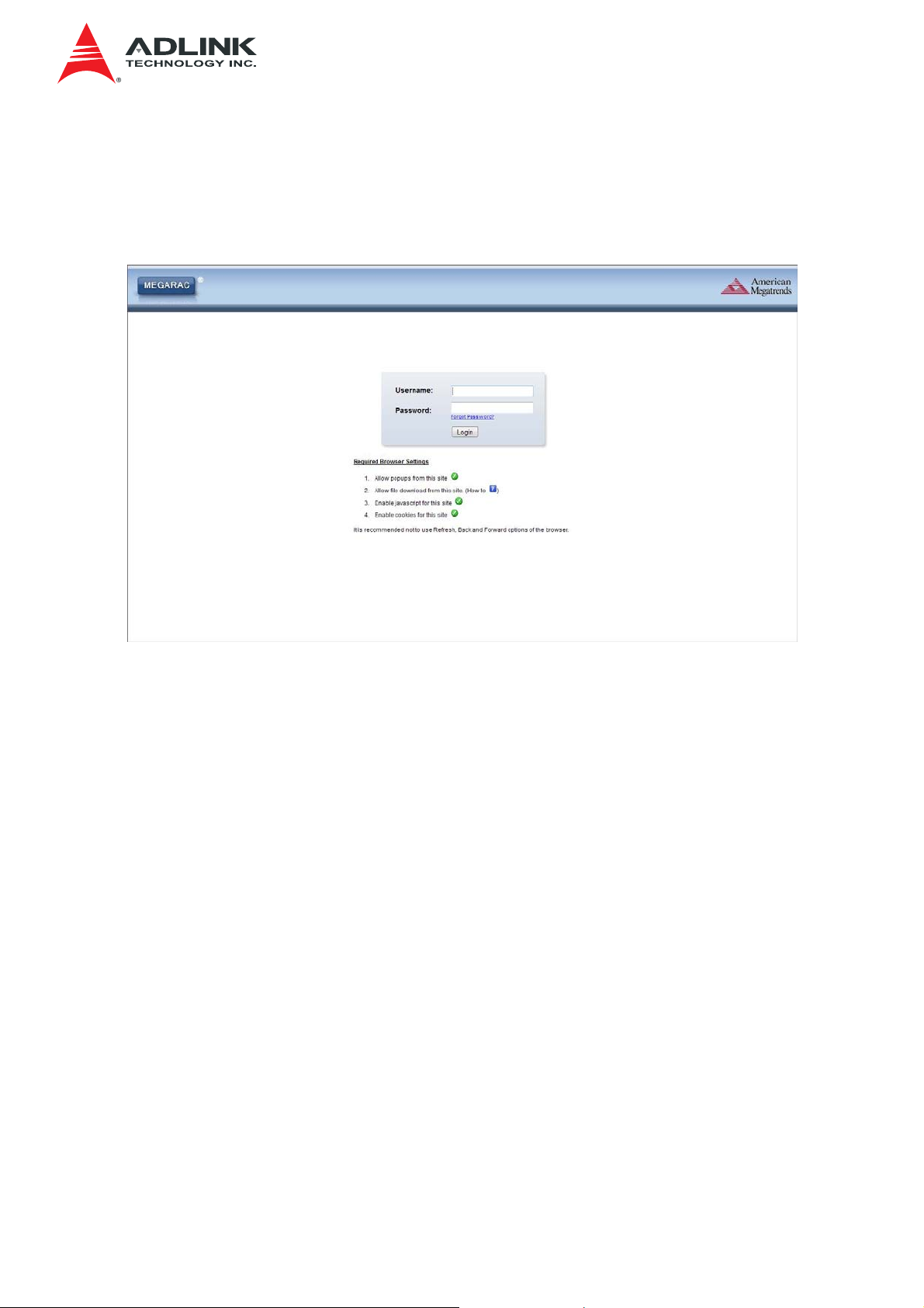
3.2 User Name and Password
Initial access of MegaRAC SP-X prompts you to enter the User Name and Password. A
screenshot of the login screen is given below.
Login Page
The fields are explained as follows:
Username: Enter your username in this field.
Password: Enter your password in this field.
Login: After entering the required credentials, click the button to login to MegaRAC GUI.
Forgot Password: If you forget your password, you can generate a new one using this
link. Enter the username, click on Forgot Password link. This will send the newly
generated password to the configured Email-ID for the user.
3.2.1 Required Browser Settings:
Allow pop-ups from this site: The icon indicates whether the browser allows popup for
this site or not.
Allow file download from this site: For Internet Explorer, Choose Tools ->Internet
Options ->Security Tab, based on device setup, select among Internet, Local intranet,
trusted sites and restricted sites. Click Custom level.... In the Security Settings - Zone
dialog opened, under settings, find Downloads option, Enable File download option. Click
OK to the entire dialog boxes.
For all Other Browsers, accept file download when prompted.
14
Page 15

IMB-S90 IPMI User’s Manual
Enable javascript for this site: The icon indicates whether the javascript setting is
enabled in browser.
Enable cookies for this site: The icon indicates whether the cookies setting are enabled
in browser.
Note: Cookies must be enabled in order to access the website.
3.2.2 Default User Name and Password
Username: admin
Password: admin
Note: The default user name and password are in lower-case characters. When you log in
using the user name and password, you get full administrative rights. It is advised to
change your password once you login.
Duplicate user names shouldn’t existing across various authentication methods like AD,
LDAP, RADIUS or IPMI since the privilege of one Authentication method is overwritten by
another authentication method when login and hence the correct privilege cannot be
returned properly.
Warning: Once you login to the application, it is recommended not to use the following
options.
• Refresh button of the browser
• Refresh menu of the browser
• Back and Forward options of the browser
• F5 on the keyboard
• Backspace on the keyboard
3.3 Using MegaRAC SP-X
The MegaRAC GUI consists of various menu items.
3.3.1 Menu Bar
The menu bar displays the following.
• Dashboard
• FRU Information
• Server Health
• Configuration
• Remote Control
15
Page 16

IMB-S90 IPMI User’s Manual
• Auto Video Recording
• Maintenance
• Firmware Update
A screenshot is of the menu bar is given below.
Menu Bar
3.3.2 Quick Button and Logged-in User
The user information and quick buttons are located at the top right of the MegaRAC® GUI.
A screenshot of the logged-in user information is shown below.
User Information
The logged-in user information shows the logged-in user, his/her privilege and the four
quick buttons allows you to perform the following functions.
3.3.3 Logged-in user and its privilege level
This option shows the logged-in user name and privilege. There are five kinds of
privileges.
User: Only valid commands are allowed.
Operator: All BMC commands are allowed except for the configuration commands that
can change the behavior of the out-of-hand interfaces.
Administrator: All BMC commands are allowed.
OEM Proprietary: The user access level defined by OEM.
No Access: Login access denied.
Refresh: Click the
Print: Click the
icon to reload the current page.
icon take the print out of the current page.
16
Page 17
IMB-S90 IPMI User’s Manual
Logout: Click the icon to log out of the MegaRAC® GUI.
HELP: Click to view the help page.
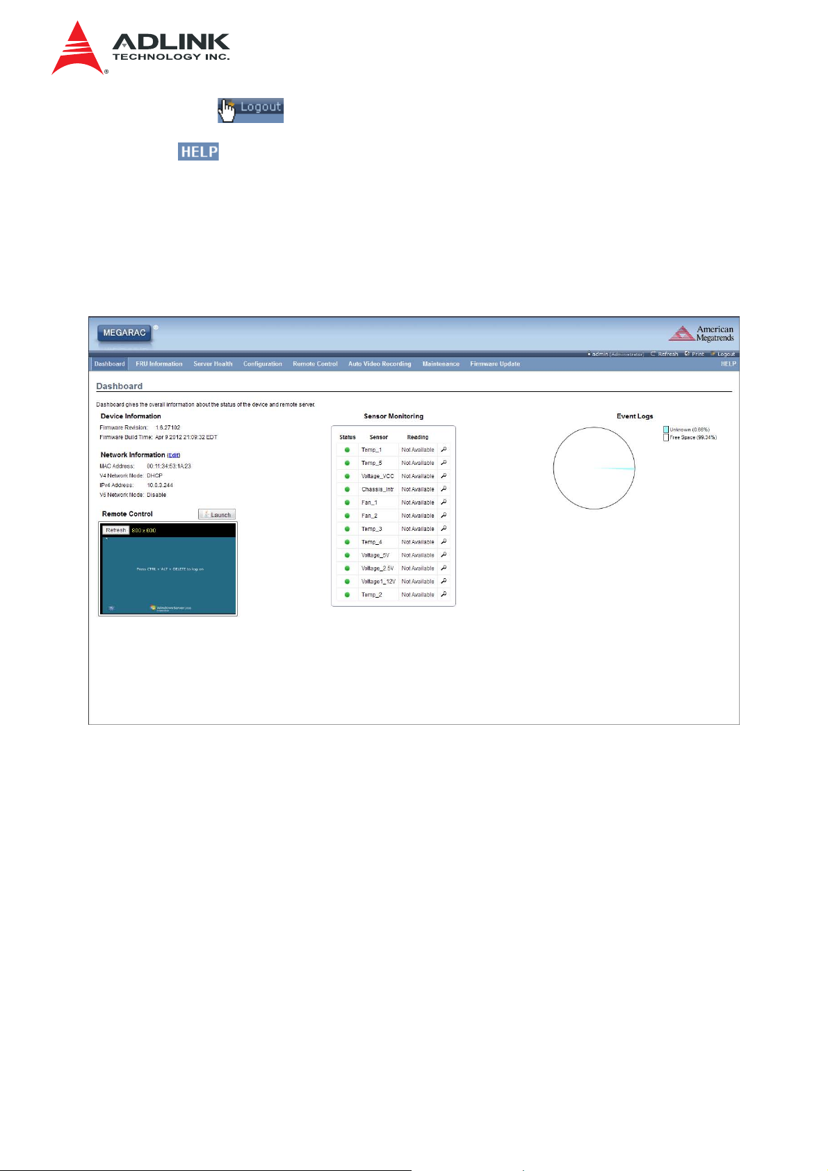
3.4 Dashboard
The Dashboard page gives the overall information about the status of a device.
To open the Dashboard page, click Dashboard from the menu bar. A sample screenshot
of the Dashboard page is shown below.
Dashboard
A brief description of the Dashboard page is given below.
3.4.1 Device Information
The Device Information displays the following information.
• Firmware Revision: The revision number of the firmware.
• Firmware Build Time: This field shows the date and time on which the firmware is
built.
3.4.2 Network Information
The Network Information of the device with the following fields is shown here. To edit the
network Information, click Edit.
17
Page 18

IMB-S90 IPMI User’s Manual
• MAC Address: Read only field showing the IP address of the device.
• V4 Network Mode: The v4 network mode of the device which could be either
disable, static or DHCP.
• IPv4 Address: The IPv4 address of the device (could be static or DHCP).
• V6 Network Mode: The v6 network mode of the device which could be either
disable, static or DHCP.
• IPv6 Address: The IPv6 address of the device.
3.4.3 Remote Control
To redirect the host remotely, click the Launch button. This downloads the jviewer.jnlp file
which after downloaded and launched will open the Java redirection window.
Note: If you wish to Launch JViewer from the Dashboard Page, the KVM option should be
enabled in the Extended Privileges for the logged in user.
3.4.4 Sensor Monitoring
It lists all the available sensors on the device with the following information’s.
• Status: This column displays the state of the device. There are three states.
• - Denotes normal state
• - Denotes Warning State
• - Denotes Critical State
• Sensor: This column states the name of the sensor.
• Reading: This column displays the value of sensor readings.
• If you click the
icon, the sensor page for that particular sensor will be displayed.
3.4.5 Event Logs
A graphical representation of all events incurred by various sensors and
occupied/available space in logs can be viewed. If you click on the color-coded rectangle
in the Legend for the chart, you can view a list of those specific events only.
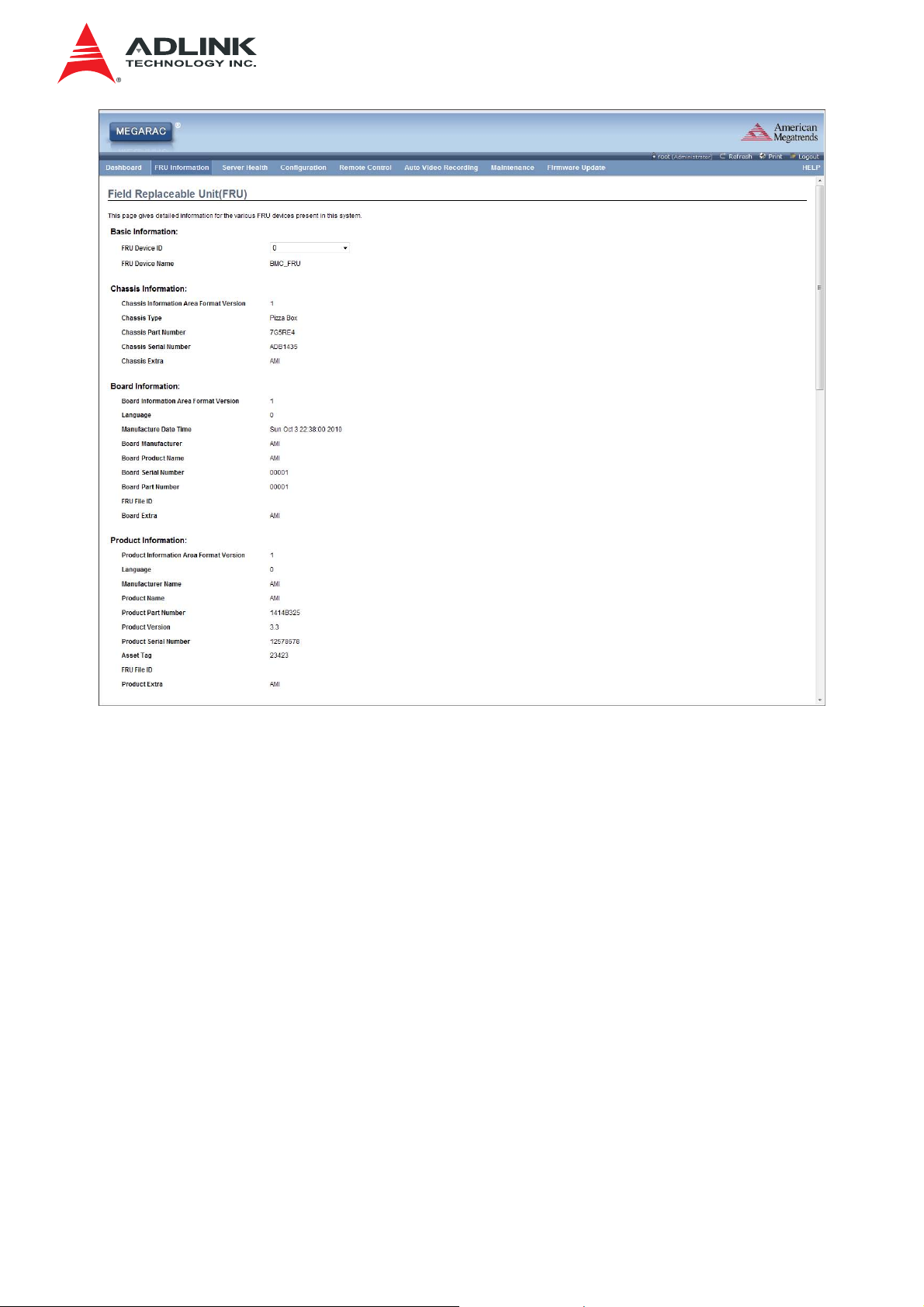
3.5 Field Replaceable Unit (FRU)
The FRU Information Page displays the BMC FRU file information. The information
displayed in this page is Basic Information, Common Header Information, Chassis
Information, Board Information and Product Information of the FRU device.
To open the FRU Information Page, click FRU Information from the menu bar. Select a
FRU Device ID from the Basic Information section to view the details of the selected
device. A screenshot of FRU Information page is given below.
18
Page 19
IMB-S90 IPMI User’s Manual
FRU Information Page
The following fields are displayed here for the selected device.
3.5.1 Basic Information
• FRU device ID - Select the device ID from the drop down list
• FRU Device Name - The device name of the selected FRU device.
3.5.2 Chassis Information
• Chassis Information Area Format Version
• Chassis Type
• Chassis Part Number
• Chassis Serial Number
• Chassis Extra
19
Page 20

3.5.3 Board Information
• Board Information Area Format Version
• Language
• Manufacture Date Time
• Board Manufacturer
• Board Product Name
• Board Serial Number
• Board Part Number
• FRU File ID
• Board Extra
IMB-S90 IPMI User’s Manual
3.5.4 Product Information
• Product Information Area Format Version
• Language
• Manufacturer Name
• Product Name
• Product Part Number
• Product Version
• Product Serial Number
• Asset Tag
• FRU File ID
• Product Extra
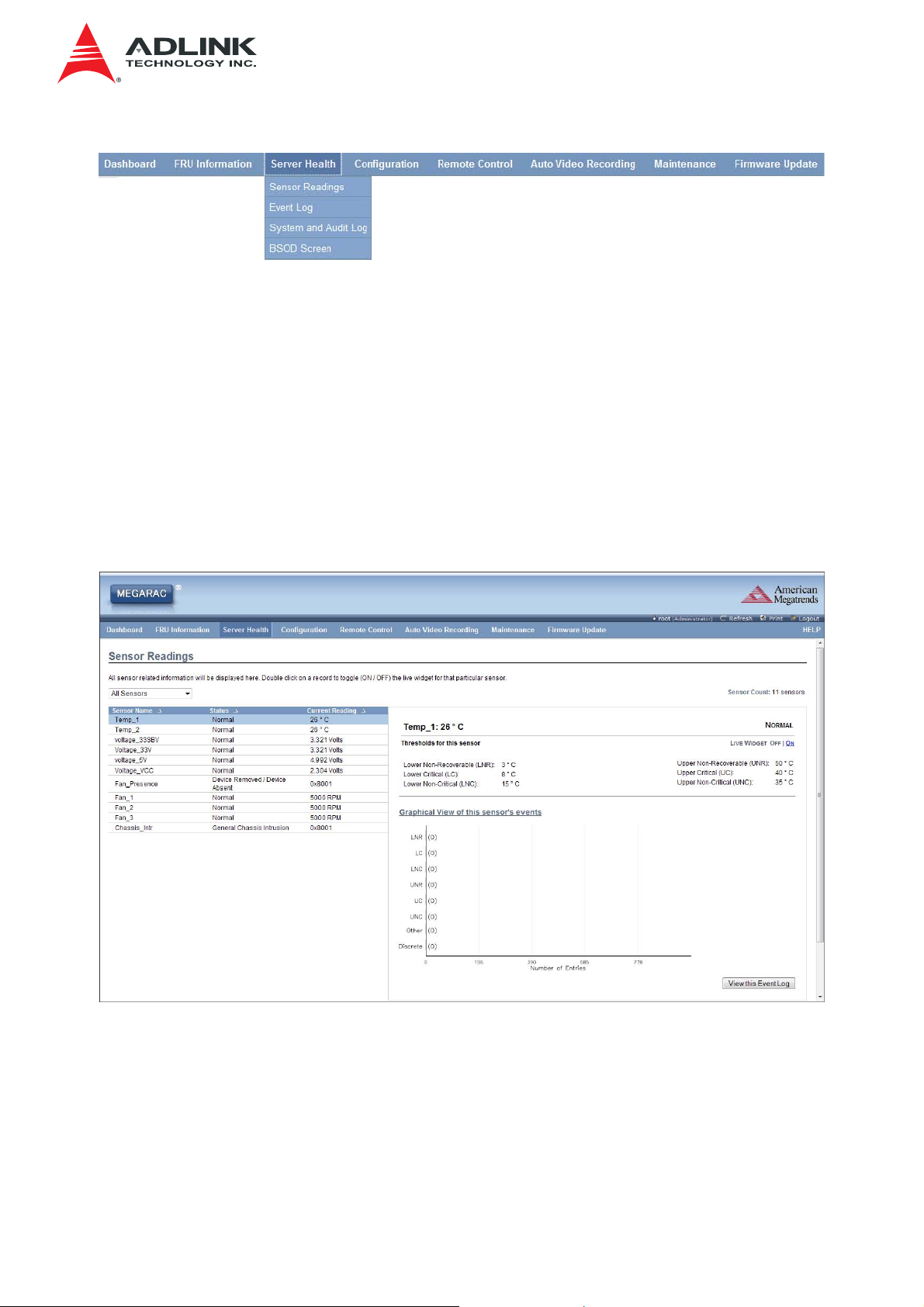
3.6 Server Health Group
The Server Health Group displays the following information.
• Sensor Readings
• Event Log
• System and Audio Log
• BSOD Screen
20
Page 21
IMB-S90 IPMI User’s Manual
A screenshot displaying the menu items under Server Health is shown below.
Server Health – Menu
A detailed description of Server Health Group is given below.
3.6.1 Sensor Readings
The Sensor Readings page displays all the sensor related information.
To open the Sensor readings page, click Server Health > Sensor Readings from the
menu. Click on a record to show more information about that particular sensor, including
thresholds and a graphical representation of all associated events. A screenshot of Sensor
Readings page is given below.
Sensor Readings Page
The Sensor Readings page contains the following information.
3.6.1.1 Sensor Type (drop down menu)
This drop down menu allows you to select the type of sensor. The List of sensors with the
Sensor Name, Status and Current Reading will be displayed in the list. If you select All
Sensors, all the available sensor details will appear else you can choose the sensor type
21
Page 22
IMB-S90 IPMI User’s Manual
that you want to display in the list. Some examples of other sensors include Temperature
Sensors, Fan Sensors, and Voltage Sensors etc.
Select a particular sensor from the list. On the right hand side of the screen you can view
the Thresholds for this sensor.
Thresholds are of six types:
• Lower Non-Recoverable (LNR)
• Lower Critical (LC)
• Lower Non-Critical (LNC)
• Upper Non-Recoverable (UNR)
• Upper Critical (UC)
• Upper Non-Critical (UNC)
The threshold states could be Lower Non-critical - going low, Lower Non-critical - going
high, Lower Critical - going low, Lower Critical - going high, Lower Non-recoverable - going
low, Lower Non-recoverable - going high, Upper Non-critical - going low, Upper Noncritical - going high, Upper Critical - going low, Upper Critical - going high, Upper Nonrecoverable - going low, Upper Non-recoverable - going high.
A graphical view of these events (Number of event logs vs. Thresholds) can be viewed as
shown in the Sensor Readings Page screenshot.
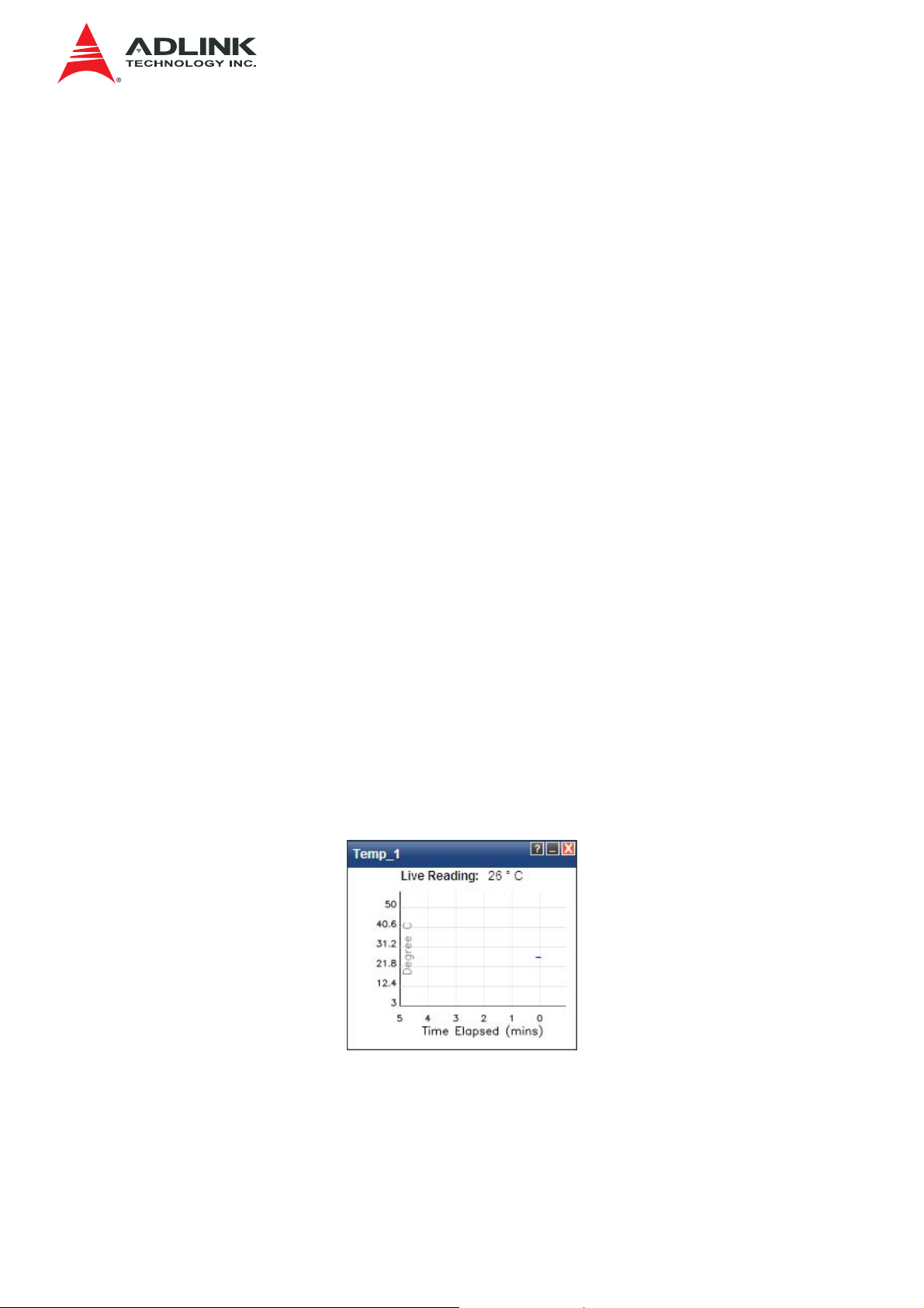
3.6.1.2 Live Widget
For the selected sensor, you can click ON or OFF to turn the widget paper or disappear.
This widget gives a dynamic representation of the readings for the sensor. You can also
double click on a record to toggle (ON / OFF) the live widget for that particular sensor.
Given below is a sample screenshot when the widget is on.
Widget
Note: Widgets are little gadgets, which provide real time information about a particular
sensor. User can track a sensor’s behavior over a specific amount of time at specific
intervals. The result will be displayed as a line graph in the widget. The session will not
expire, until the widgets gets a live data of the last widget that is kept opened.
22
Page 23
IMB-S90 IPMI User’s Manual
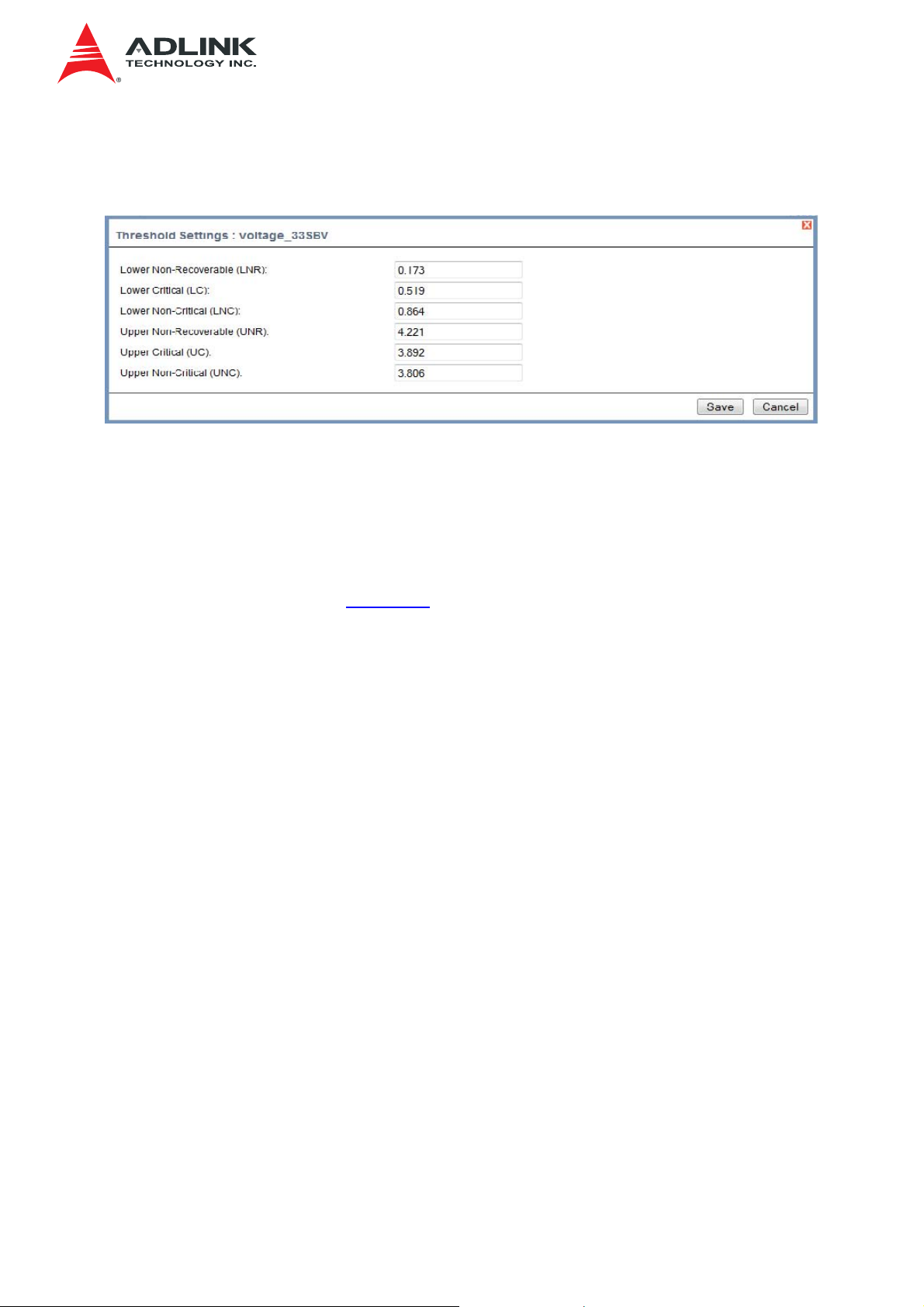
3.6.1.3 Threshold Settings
The threshold settings can be configured by clicking this button. A sample screenshot is
given below.
Threshold Settings
Enter the Threshold values and click Save to configure the threshold values.
3.6.1.4 View this Event Log
You can click here to view the “Event Log” for the selected sensor.
3.6.2 Event Log
This page displays the list of event logs occurred by the different sensors on this device.
Double click on a record to see the details of that entry. You can use the sensor type or
sensor name filter options to view those specific events or you can also sort the list of
entries by clicking on any of the column headers.
23
Page 24

IMB-S90 IPMI User’s Manual
To open the Event Log page, click Server Health > Event Log from the menu bar. A
sample screenshot of Event Log page is shown below.
Event Log Page
The Event Log page consists of the following Fields.
Event log Category: The category could be either All Events, System Event Records,
OEM Event Records, BIOS Generated Events, SMI Handler Events, System Management
Software Events, System Software - OEM Events, Remote Console software Events,
Terminal Mode Remote Console software Events.
Filter By: Filtering can be done with the sensors mentioned in the list.
Note: Once the Event Log category and Filter type are selected, the list of events will be
displayed with the Event ID, Time Stamp, Sensor Type, Sensor Name and Description.
BMC Timezone: Displays the BMC UTC Offset timestamp value of the events.
Client Timezone: Displays the events of Client UTC Offset timestamp.
UTC Offset: Displays the current UTC Offset value based on which event Time Stamps
will be updated. Navigational arrows can be used to selectively access different pages of
the Event Log.
Clear All Event Logs: To delete all the existing records for all the sensors.
Save Event Logs: To save all existing Event Log records.
24
Page 25
IMB-S90 IPMI User’s Manual
3.6.2.1 Procedure:
1. From the Event Log Category drop down menu, select the event categories.
2. From the Filter Type drop-down list, select the sensor name filter to view the event
for the selected filter.
3. Select either BMC Timezone or Client Timezone. The events will be displayed
based on the selected time zone value.
4. To clear all events from the list, click Clear All Event Logs button.
5. To save all the existing event logs, click Save Event Logs button.
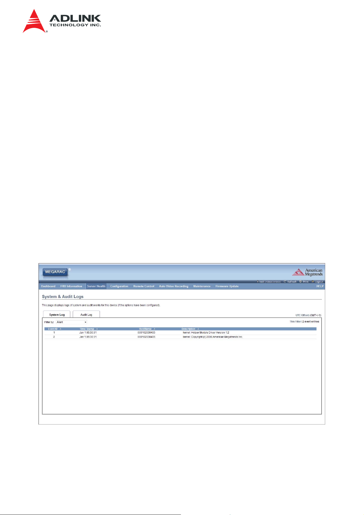
3.6.3 System & Audit logs
The System and Audit Log page logs will display all the system and audit events that
occurred in this device only if it has been already configured.
Note: Logs have to be configured under Configuration -> System and Audit Log in order
to display any entries.
To open the Event Log page, click Server Health > System and Audit Log from the
menu bar.
A sample screenshot of System and Audit Log page is shown below.
System and Audit Log
25
Page 26
IMB-S90 IPMI User’s Manual
3.6.3.1 Procedure
To view System Log, click the System Log tab to view all system events. Entries can be
filtered based on their levels like Alert, Critical, Error, Notification, Warning, Debug,
Emergency and Information.
To view Audit Log, click the Audit Log tab to view all audit events for this device.
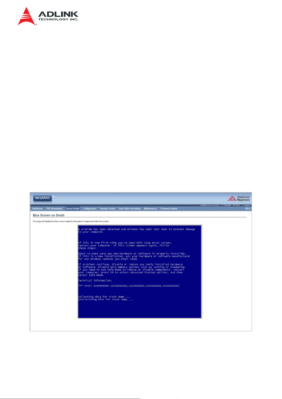
3.6.4 Blue Screen of Death
This page displays the blue screen captured during failure in host system.
To open the BSOD Screen page, click Server Health > BSOD Screen from the menu
bar. A sample screenshot of BSOD Screen page is shown below.
Note:
• KVM service should be enabled, to display the BSOD screen. KVM Service can be
configured under Configuration-> Services->KVM.
• Depending on the PRJ configuration in MDS, the image will be saved as JPEG or
raw data.
A sample screenshot of BSOD Screen is shown below.
BSOD Screen
26
Page 27
IMB-S90 IPMI User’s Manual
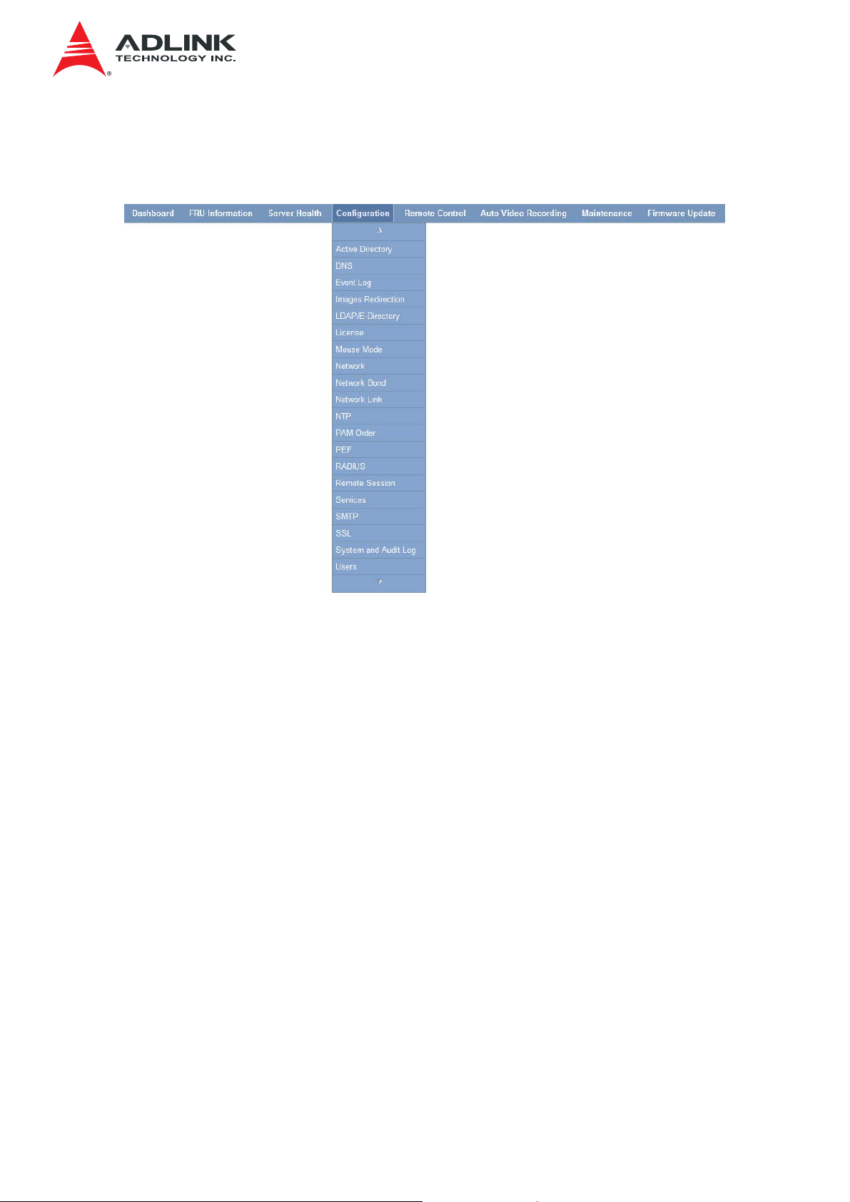
3.7 Configuration Group
This group of pages allows you to access various configuration settings. A screenshot of
Configuration Group menu is shown below.
Configuration Group Menu
A detailed description of the Configuration menu is given below.
3.7.1 Active Directory
An active directory is a directory structure used on Microsoft Windows based computers
and servers to store information and data about networks and domains. An active directory
(sometimes referred to as AD) does a variety of functions including the ability to provide
information on objects. It also helps to organize these objects for easy retrieval and
access, allows access by end users and administrators and allows the administrator to set
security up for the directory.
In MegaRAC SP-X application, Active Directory allows you to configure the Active
Directory Server Settings. The displayed table shows any configured Role Groups and the
available slots. You can modify, add or delete role groups from here. Group domain can be
the AD domain or a trusted domain. Group Name should correspond to the name of an
actual AD group.
Note: To view the page, you must be at least a User and to modify or add a group, you
must be an Administrator.
To open Active Directory Settings page, click Configuration > Active Directory from the
menu bar. A sample screenshot of Active Directory Settings page is shown below.
27
Page 28

Active Directory Settings Page
The fields of Active Directory page are explained below.
IMB-S90 IPMI User’s Manual
Advanced Settings: This option is used to configure Active Directory Advanced Settings.
Options are Enable Active Directory Authentication, Secret User Name, Secret Password,
User Domain name, Time Out and up to three Domain Controller Server Addresses.
Role Group Name: The name that identifies the role group in the Active Directory.
Note: Role Group Name is a string of 255 alpha-numeric characters. Special symbols
hyphen and underscore are allowed.
Group Name: This name identifies the role group in Active Directory.
Note: Role Group Name is a string of 255 alpha-numeric characters. Special symbols
hyphen and underscore are allowed.
Group Domain: The domain where the role group is located.
Note: Domain Name is a string of 255 alpha-numeric characters. Special symbols hyphen,
underscore and dot are allowed.
Group Privilege: The level of privilege to assign to this role group.
Add Role Group: To add a new role group to the device.
Modify role Group: To modify the existing role group.
Delete Role Group: To delete an existing Role Group.
3.7.1.1 Procedure:
Entering the details in Advanced Active Directory Settings Page
1. Click on Advanced Settings to open the Advanced Active Directory Settings Page.
28
Page 29

IMB-S90 IPMI User’s Manual
Advanced Active Directory Settings Page
2. In the Active Directory Settings, Page, check or uncheck the Enable checkbox to
enable or disable Active Directory Authentication respectively.
Note: If you have enabled Active Directory Authentication, enter the required
information to access the Active Directory server.
3. Specify the Secret user name and password in the Secret User Name and Secret
Password fields respectively.
Note:
• Secret username/password for AD is not mandatory. If the AD’s secret
username/password is not provided, AD should be kept in the last location in
PAM order.
• User Name is a string of 1 to 64 alpha-numeric characters.
• It must start with an alphabetical character.
• It is case-sensitive.
• Special characters like comma, period, colon, semicolon, slash, backslash,
square brackets, angle brackets, pipe, equal, plus, asterisk, question mark,
ampersand, double quotes, space are not allowed.
• Password must be at least 6 characters long and will not allow more than 127
characters.
• White space is not allowed.
4. Specify the Domain Name for the user in the User Domain Name field. E.g.
MyDomain.com
5. Specify the time (in seconds) to wait for Active Directory queries to complete in the
Time Out field.
Note:
• Default Time out value: 120 seconds.
• Range from 15 to 300 allowed.
29
Page 30
IMB-S90 IPMI User’s Manual
6. Configure IP addresses in Domain Controller Server Address1, Domain Controller
Server Address2 & Domain Controller Server Address3.
Note: IP address of Active Directory server: At least one Domain Controller Server
Address must be configured.
• IP Address made of 4 numbers separated by dots as in “xxx.xxx.xxx.xxx”.
• Each number ranges from 0 to 255.
• First number must not be 0.
• Domain Controller Server Addresses will supports IPv4 Address format and
IPv6 Address format.
7. Click Save to save the entered settings and return to Active Directory Settings
Page.
8. Click Cancel to cancel the entry and return to Active Directory Settings Page.
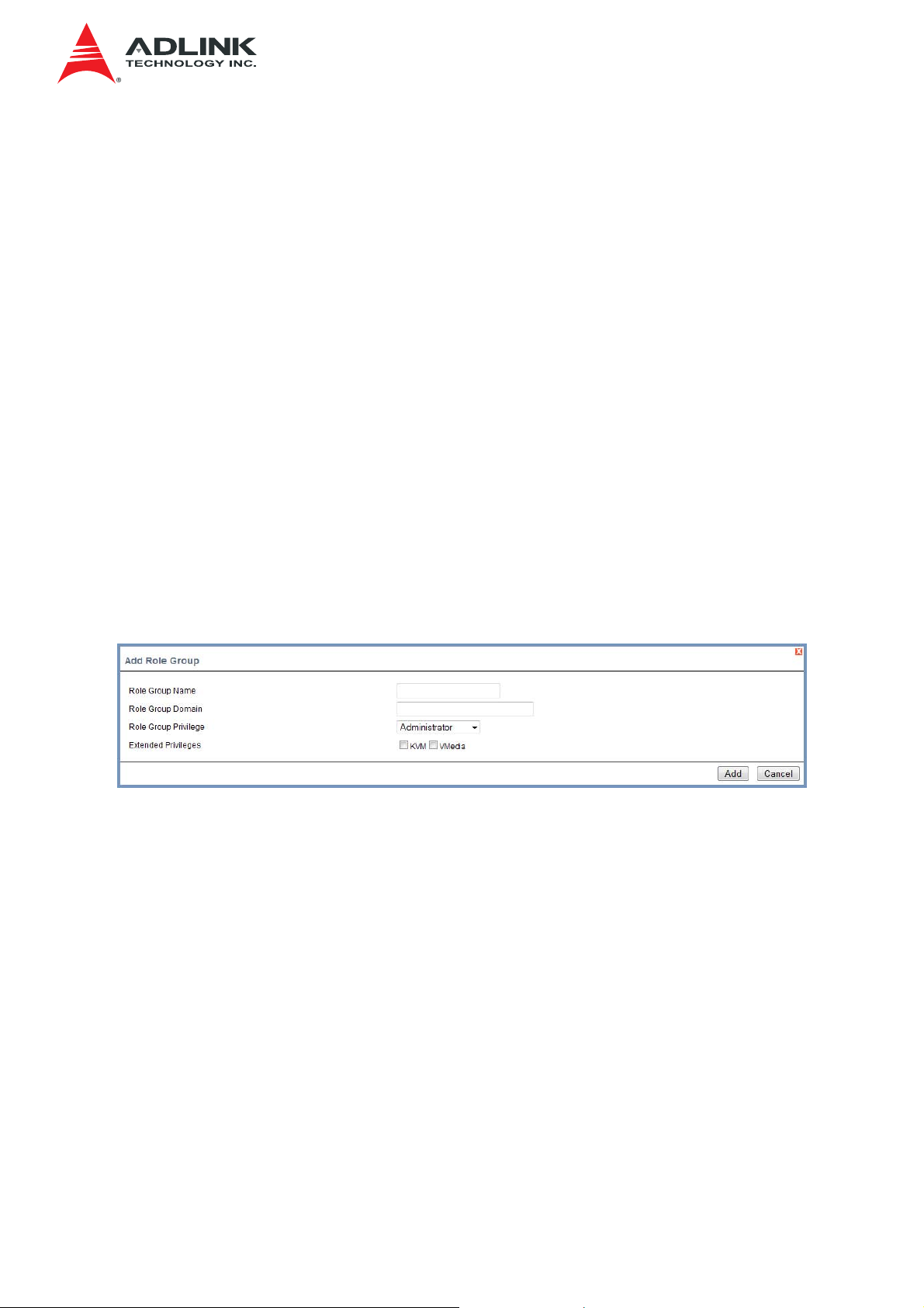
3.7.1.1.1 To add a new Role Group
9. In the Active Directory Settings Page, select a blank row and click Add Role Group
or alternatively double click on the blank row to open the Add Role group Page as
shown in the screenshot below.
Add Role group Page
10. In the Role Group Name field, enter the name that identifies the role group in the
Active Directory.
Note:
• Role Group Name is a string of 255 alpha-numeric characters.
• Special symbols hyphen and underscore are allowed.
11. In the Role Group Domain field, enter the domain where the role group is located.
Note:
• Domain Name is a string of 255 alpha-numeric characters.
• Special symbols hyphen, underscore and dot are allowed.
30
Page 31

IMB-S90 IPMI User’s Manual
12. In the Role Group Privilege field, enter the level of privilege to assign to this role
group.
13. In the Extended Privileges option, select the required options
• KVM
• VMedia
14. Click Add to save the new role group and return to the Role Group List.
15. Click Cancel to cancel the settings and return to the Role Group List.
3.7.1.1.2 To Modify Role Group
16. In the Advanced Directory Settings Page, select the row that you wish to modify
and click Modify Role Group or double click the row that you wish to modify.
17. Make the necessary changes and click Save.
3.7.1.1.3 To Delete a Role Group
18. In the Advanced Directory Settings Page, select the row that you wish to delete.
19. Click Delete Role Group.
3.7.2 DNS
The Domain Name System (DNS) is a distributed hierarchical naming system for
computers, services, or any resource connected to the Internet or a private network. It
associates the information with domain names assigned to each of the participants. Most
importantly, it translates domain names meaningful to humans into the numerical (binary)
identifiers associated with networking equipment for the purpose of locating and
addressing these devices worldwide.
The DNS Server settings page is used to manage the DNS settings of a device.
To open DNS Server Settings page, click Configuration > DNS from the menu bar. A
sample screenshot of DNS Server Settings page is shown below.
31
Page 32

IMB-S90 IPMI User’s Manual
DNS Server Settings Page
The fields of DNS Server Settings page are explained below.
3.7.2.1 Host configuration
• Host Settings: Choose either Automatic or Manual settings.
• Host Name: It displays host name of the device. If the Host setting is chosen as
Manual, then specify the host name of the device.
Note:
• Value ranges from 1 to 64 alpha-numeric characters.
• Special characters ‘-’(hyphen) and ‘_’(underscore) are allowed.
• It must not start or end with a ‘-’(hyphen). IE browsers won’t work correctly if any
part of the host name contain underscore (_) character.
3.7.2.2 Register BMC
• Option to register the BMC either through Direct Dynamic DNS or through DHCP
Client FQDN.
3.7.2.3 TSIG Configuration
TSIG Authentication: To enable/disable TSIG authentication while registering DNS via
Direct Dynamic DNS.
Current TSIG Private File: The information as Current TSIG private and uploaded
date/time will be displayed (read only).
32
Page 33

IMB-S90 IPMI User’s Manual
New TSIG Private File: Browse and navigate to the TSIG private file.
Note: TSIG file should be of private type
3.7.2.4 Domain Name Configuration
• Domain Settings: It lists the option for domain interface as Manual, v4 or v6 for
multiLAN channels.
Note: If you choose DHCP, then select v4 or v6 for DHCP servers.
• Domain Name: It displays the domain name of the device. If the Domain setting is
chosen as Manual, then specify the domain name of the device. If you chose
Automatic, the Domain Name cannot be configured as it will be done automatically.
The field will be disabled.
3.7.2.5 Domain Name Server Configuration
• DNS Server Settings: It lists the option for v4 DNS settings for the device, Manual
and available LAN interfaces.
• IP Priority:
• If IP Priority is IPv4, it will have 2 IPv4 DNS servers and 1 IPv6 DNS server.
• If IP Priority is IPv6, it will have 2 IPv6 DNS servers and 1 IPv4 DNS server.
Note: This is not applicable for Manual configuration.
• DNS Server 1, 2 & 3
To specify the DNS (Domain Name System) server address to be configured for the
BMC.
Note:
• IPv4 Address made of 4 numbers separated by dots as in “xxx.xxx.xxx.xxx”.
• Each number ranges from 0 to 255.
• First number must not be 0.
DNS Server Address will support the following:
• IPv4 Address format.
• IPv6 Address format.
Save: To save the entered changes.
Reset: To reset the entered changes.
33
Page 34

IMB-S90 IPMI User’s Manual
3.7.2.5.1 Procedure:
1. Choose the Host Configuration either Automatic or Manual
Note: If you choose Automatic, you need not enter the Host Name and if you
choose Manual, you need to enter the Host Name.
2. Enter the Host Name in the given field if you have chosen Manual Configuration.
3. Under Register BMC, choose the BMC’s network port to register with this DNS
settings.
• Check the option Register BMC to register with this DNS settings.
• Choose the option Direct Dynamic DNS to register with direct dynamic DNS
or choose DHCP Client FQDN to register through DHCP server.
4. IN TSIG Configuration, Enable TSIG Authentication.
• The current file name will be displayed in Current TSIG Private file.
• To view a new one, browse and navigate to the TSIG private file
5. In the Domain name Configuration Settings,
• Select the domain settings from the drop-down list.
• Enter the Domain Name in the given field.
6. In Domain Name Server Configuration,
• Select the DNS Server Settings, from the drop-down list.
• Choose the IP Priority, either IPv4 or IPv6.
• Enter the DNS Server address.
7. In DNS Server1, DNS Server2 and DNS Server3, enter the server addresses to be
configured for the BMC.
8. Click Save to save the entries.
9. Click Reset to reset the entries.
3.7.3 System Event Log
This page is used to configure the SEL type, that is Linear SEL or Circular SEL. Linear
SEL type will store the System Event log linearly up to its SEL Repository size and SEL
will be discarded if the SEL Repository is full. Circular SEL type will store the System
Event log linearly up to its SEL Repository size and override the SEL entry if the SEL
Repository is full.
To open System Event log page, click Configuration > Event Log from the menu bar. A
sample screenshot of System Event log page is shown below.
34
Page 35

IMB-S90 IPMI User’s Manual
System Event Log Page
The fields of System Event Log page are explained below.
Current Event Log Policy: Displays the configured Event Log Policy.
• Enable Linear Event Log Policy: To enable the Linear System Event Log Policy
for Event Log.
• Enable Circular Event Log Policy: To enable the Circular System Event Log
Policy for Event Log.
Save: To save the configured settings.
Reset: To reset the modified changes.
3.7.3.1 Procedure:
Choose either Enable Linear Event Log Policy or Enable Circular Event Log Policy
and click Save to save the changes.
3.7.4 Images Redirection
This page is used to configure the images into BMC for redirection. This can be done
either by uploading an image into BMC say, Local Media or by mounting the image from
the remote system, Remote Media.
To open Images Redirection page, click Configuration > Images Redirection from the
menu bar. A sample screenshot of Images Redirection page is shown below.
35
Page 36

Images Redirection
The fields of Images Redirection page are explained below.
• Local Media
IMB-S90 IPMI User’s Manual
• Remote Media
3.7.4.1 Advanced Setting for Media Redirection
Enter the Advanced Media Settings for media redirection.
Advanced Media Settings
Local Media Support: To enable or disable Local Media support, check or uncheck the
‘Enable’ checkbox respectively.
Remote Media Support: To enable or disable Remote Media support, check or uncheck
the ‘Enable’ checkbox respectively.
Note: Both local and remote media support can be enabled at a time
Server Address: Server address of the remote media images are stored.
Source Path: Source path of the remote media images are stored.
36
Page 37

IMB-S90 IPMI User’s Manual
Share Type: Share Type of the remote media server either NFS or Samba(CIFS).
Username, Password and Domain Name: If share Type is Samba(CIFS), then user
credentials to authenticate the server.
Save: To save the settings.
Cancel: To cancel the modifications and return to Image list.
3.7.4.2 Local Media
This tab displays the list of available images in the local media on BMC. You can replace
or add new images from here. To configure the image, you need to enable Local Media
support under Images Redirection -> Advanced Settings. Once you enable this option,
the user can add the images and the added images will be redirected to the host machine
Note:
To replace or add an image, you must have Administrator Privileges.
Only one image can be uploaded for each image type. If the existing image and uploading
image name is same, then a message is shown “Image already exists”.
In Local Media redirection, the maximum upload size is 8MB.
The fields of Local Media tab is as follows:
Add Image: To upload a new image to the device.
Replace Image: To replace the existing image.
Delete Image: To delete the desired image.
3.7.4.2.1 Procedure:
1. To add, remove or modify images, click Advanced Settings and make sure Local
Media Support option is enabled. If not, disable Remote Media Redirection and then
enable Local Media Redirection.
2. Click on the Local Media Tab.
3. To add an image, select a free slot and click Add Image to upload a new image to
the device. Alternatively, double click on a free slot to add an image. A sample
screenshot of Add Image screen is given below.
Add Image
37
Page 38

IMB-S90 IPMI User’s Manual
4. To replace an image, select a configured slot and click Replace Image to replace
the existing image. Alternatively, double click on the configured slot.
5. Browse the image File and click Replace
6. To delete an image, select a record and click Delete Image to delete the selected
image.
3.7.4.3 Remote Media
The displayed table shows configured images on BMC. You can configure images of the
remote media server.
Images Redirection
Note:
Only one image can be configured for each image type.
To configure the image, you need to enable Remote Media support using ‘Advanced
Settings’.
To add or replace an image, you must have Administrator Privileges.
Free slots are denoted by “~”
The fields of Remote Media tab are as follows:
Start/Stop Redirection: To start or stop Media redirection.
Add Image: To upload a new image to the device.
Replace Image: To replace the existing image.
Delete Image: To delete the desired image.
3.7.4.3.1 Procedure:
1. To Start/Stop Redirection and configure remote media images, click Advanced
Settings and make sure Remote Media Support option is enabled. If not, disable
Local Media Redirection and then enable Remote Media Redirection.
38
Page 39

IMB-S90 IPMI User’s Manual
Note: The Start Redirection button is active only for VMedia enabled users.
2. Select a configured slot and click Start Redirection to start the remote media
redirection. It is a toggle button, if the image is successfully redirected, then click
Stop Redirection to stop the remote media redirection.
3. To add an image, select a free slot and click Add Image to configure a new image
to the device. Alternatively, double click on a free slot to add an image.
4. To replace an image, select a configured slot and click Replace Image to replace
the existing image. Alternatively, double click on the configured slot.
5. To delete an image, select the desired image to be deleted and click Delete Image.
Note: Redirection needs to be stopped to replace or delete the image.
3.7.5 LDAP/E-Directory Settings
The Lightweight Directory Access Protocol (LDAP)/E-Directory Settings is an
application protocol for querying and modifying data of directory services implemented in
Internet Protocol (IP) networks.
In MegaRAC GUI, LDAP is an Internet protocol that MegaRAC® card can use to
authenticate users. If you have an LDAP server configured on your network, you can use it
as an easy way to add, manage and authenticate MegaRAC® card users. This is done by
passing login requests to your LDAP Server. This means that there is no need to define an
additional authentication mechanism, when using the MegaRAC card. Since your existing
LDAP Server keeps an authentication centralized, you will always know who is accessing
the network resources and can easily define the user or group-based policies to control
access.
To open LDAP/E-DIRECTORY Settings page, click Configuration > LDAP/E-Directory
from the menu bar. A sample screenshot of LDAP/E-Directory Settings page is shown
below.
LDAP/E-Directory Settings Page
39
Page 40

IMB-S90 IPMI User’s Manual
The fields of LDAP/E-Directory Settings Page are explained below.
Advanced Settings: To configure LDAP/E-Directory Advanced Settings. Options are
Enable LDAP/E-Directory Authentication, IP Address, Port and Search base.
Add Role Group: To add a new role group to the device. Alternatively, double click on a
free slot to add a role group.
Modify Role Group: To modify the particular role group.
Delete Role Group: To be delete a role group from the list.
3.7.5.1 Procedure
3.7.5.1.1 Entering the details in Advanced LDAP/E-Directory Settings Page
1. In the LDAP/E-Directory Settings Page, click Advanced Settings. A sample
screenshot of Advanced LDAP/E-Directory Settings page is given below.
Advanced LDAP/E-Directory Settings
2. To enable/disable LDAP/E-Directory Authentication, check or uncheck the Enable
checkbox respectively.
Note:
During login prompt, use username to login as an ldap Group member.
3. Enter the IP address of LDAP server in the Server Address field.
Note:
IP Address made of 4 numbers separated by dots as in ‘xxx.xxx.xxx.xxx’.
Each Number ranges from 0 to 255.
First Number must not be 0.
Supports IPv4 Address format and IPv6 Address format.
4. Specify the LDAP Port in the Port field.
40
Page 41

Note:
Default Port is 389. For Secure connection, default port is 636.
5. Specify the Bind DN:
Note:
Bind DN is a string of 4 to 64 alpha-numeric characters.
It must start with an alphabetical character.
Special Symbols like dot(.), comma(,), hyphen(-), underscore(_), equal-to(=) are
allowed.
Example: cn=manager,ou=login, dc=domain,dc=com
6. Enter the password in the Password field.
IMB-S90 IPMI User’s Manual
Note:
Password must be at least 1 character long.
White space is not allowed.
This field will not allow more than 48 characters.
7. Enter the Search Base. The Search base tells the LDAP server which part of the
external directory tree to search. The search base may be something equivalent to
the organization, group of external directory.
Note:
Search base is a string of 4 to 63 alpha-numeric characters.
It must start with an alphabetical character.
Special Symbols like dot(.), comma(,), hyphen(-), underscore(_), equal-to(=) are
allowed.
Example: ou=login,dc=domain,dc=com
8. Click Save to save the settings.
9. Click Cancel to cancel the modified changes.
3.7.5.1.2 To add a new Role Group
10. In the LDAP/E-Directory Settings Page, select a blank row and click Add Role
Group or alternatively double click on the blank row to open the Add Role group
Page as shown in the screenshot below.
41
Page 42

IMB-S90 IPMI User’s Manual
Add Role group Page
11. In the Role Group Name field, enter the name that identifies the role group.
Note:
Role Group Name is a string of 255 alpha-numeric characters.
Special symbols hyphen and underscore are allowed.
12. In the Role Group Search Base field, enter the path from where the role group is
located to Base DN.
Note:
Search Base is a string of 255 alpha-numeric characters.
Special symbols hyphen, underscore and dot are allowed.
13. In the Role Group Privilege field, enter the level of privilege to assign to this role
group.
14. In the Extended Privileges option, select the required options
• KVM
• VMedia
15. Click Add to save the new role group and return to the Role Group List.
16. Click Cancel to cancel the settings and return to the Role Group List.
3.7.5.1.3 To Modify Role Group
17. In the LDAP/E-Directory Settings Page, select the row that you wish to modify and
click Modify Role Group or double click the row that you wish to modify.
18. Make the necessary changes and click Save.
3.7.5.1.4 To Delete a Role Group
19. In the LDAP/E-Directory Settings Page, select the row that you wish to delete.
20. Click Delete Role Group.
42
Page 43

IMB-S90 IPMI User’s Manual
3.7.6 License
The License page is used to display the available services and it’s validity period.
To open License page, click Configuration > License from the menu bar. A sample
screenshot of License Page is shown below.
License
The fields of License page are explained below.
Upload License Key: This button is used to add a license key to activate the particular
service.
Feature Name: This field is used to list all the available services.
Validity: This field is used to show the validity of the particular service.
Note: Validity period mentioned in days.
3.7.6.1 Procedure
1. To add a license key, click Upload License Key button. This opens the Upload
license Key window as shown below.
Upload License Key
2. Enter the License Key.
3. Click Add to add the license key.
4. Click Cancel to go back to the License page.
5. The added license can be seen in the grid.
43
Page 44

IMB-S90 IPMI User’s Manual
3.7.7 Mouse Mode
In MegaRAC GUI, Redirection Console handles mouse emulation from local window to
remote screen in either of two methods. User has to be an Administrator to configure this
option.
To view the Supported Operating Systems for Mouse Mode, click here.
To open Mouse Mode page, click Configuration > Mouse Mode from the menu bar. A
sample screenshot of Mouse Mode Settings Page is shown below.
Mouse Mode Settings Page
The fields of Mouse Mode Settings page are explained below.
Absolute Mode: The absolute position of the local mouse is sent to the server.
Relative Mode: Relative mode sends the calculated relative mouse position displacement
to the server.
Other Mode: To have the calculated displacement from the local mouse in the center
position sent to the server.
Save: To save the changes made.
Reset: To Reset the modified changes.
3.7.7.1 Procedure
1. Choose either of the following as your requirement:
• Set mode to Absolute
Note: Applicable for all Windows versions, versions above RHEL6, and
versions above FC14
• Set mode to Relative radio
Note: Applicable for all Linux versions, versions less than RHEL6, and
versions less than FC14
• Set Mode to Other Mode
44
Page 45

IMB-S90 IPMI User’s Manual
Note: Recommended for SLES-11 OS Installation
2. Click Save button to save the changes made.
3. Click Reset to reset the modified changes.
3.7.8 NCSI
In MegaRAC GUI, this page is used to configure Network Controller Sideband Interface
(NCSI) configuration settings.
To open NCSI page, click Configuration > NCSI from the menu bar. A sample
screenshot of NCSI Page is shown below.
Configure NCSI
The following fields are displayed in this page
NCSI Interface: It lists the interface name in list box.
Channel Number: Lists the channel number of the selected interface.
Package ID: Lists the package id of the selected interface.
Save: To save the current changes.
Reset: To reset the modified changes.
3.7.8.1 Procedure
1. Choose the particular NCSI Interface to which you need to configure NCSI settings.
2. Choose the Channel Number to be configured for the selected Interface name.
3. Choose the Package ID to be configured for the selected Interface name.
4. Click Save to save the current changes.
5. Click Reset to reset the modified changes.
45
Page 46

IMB-S90 IPMI User’s Manual
3.7.9 Network
In MegaRAC GUI, the Network Settings Page is used to configure the network settings for
the available LAN channels.
To open Network Settings page, click Configuration > Network from the menu bar. A
sample screenshot of Network Settings Page is shown below.
Network Settings Page
The fields of Network Settings page are explained below.
LAN Interface: Lists the LAN interfaces.
LAN Settings: To enable or disable the LAN Settings.
MAC Address: This field displays the MAC Address of the device. This is a read only
field.
IPv4 Settings: This option lists the IPv4 configuration settings.
Obtain IP Address automatically: This option is to dynamically configure IPv4 address
using DHCP (Dynamic Host Configuration Protocol).
IPv4 Address, Subnet Mask, and Default Gateway: These fields are for specifying the
static IPv4 address, Subnet Mask and Default Gateway to be configured to the device.
46
Page 47

IMB-S90 IPMI User’s Manual
Note:
• IP Address made of 4 numbers separated by dots as in “xxx.xxx.xxx.xxx”.
• Each Number ranges from 0 to 255.
• First Number must not be 0.
IPv6 Configuration: This option lists the following IPv6 configuration settings.
IPv6 Settings: This option is to enable/disable the IPv6 settings in the device.
Obtain an IPv6 address automatically: This option is to dynamically configure IPv6
address using DHCP (Dynamic Host Configuration Protocol).
IPv6 Address: To specify a static IPv6 address to be configured to the device. Eg:
2004::2010
Subnet Prefix length: To specify the subnet prefix length for the IPv6 settings.
Note:
• Value ranges from 0 to 128.
Default Gateway: Specify v6 default gateway for the IPv6 settings.
VLAN Configuration: It lists the VLAN configuration settings.
VLAN Settings: To enable/disable the VLAN support for selected interface.
VLAN ID: The Identification for VLAN configuration.
Note:
• Value ranges from 1 to 4095.
VLAN Priority: The priority for VLAN configuration.
Note:
• Value ranges from 1 to 7.
• 7 is the highest priority for VLAN.
Save: To save the entries.
Reset: To Reset the modified changes.
3.7.9.1 Procedure
1. Select the LAN Interface from the drop down list.
2. Check Enable to enable the LAN Settings.
47
Page 48

IMB-S90 IPMI User’s Manual
3. In IPv4 Configuration, enable Use DHCP to Obtain an IP address automatically
to dynamically configure IPv4 address using DHCP.
4. If the field is disabled, enter the IPv4 Address, Subnet Mask and Default
Gateway in the respective fields.
5. In IPv6 Configuration, if you wish to enable the IPv6 settings, check Enable.
6. If the IPv6 setting is enabled, enable or disable the option Use DHCP for obtaining
the IP address automatically.
7. If the field is disabled, enter the IPv6 Address, Subnet Prefix length and Default
Gateway in the given field.
8. In VLAN Configuration, if you wish to enable the VLAN settings, check Enable.
9. Enter the VLAN ID in the specified field.
10. Enter the VLAN Priority in the specified field.
11. Click Save to save the entries.
12. Click Reset if you want to reset the modified changes.
3.7.10 Network Link
In MegaRAC GUI, this page is used to configure the network link configuration for
available network interfaces.
To open Network Link page, click Configuration > Network Link from the menu bar. A
sample screenshot of Network Link Page is shown below.
Network Link Page
The fields of Network Link page are explained below.
LAN Interface: Select the required network interface from the list to which the Link speed
and duplex mode to be configured.
Auto Negotiation: This option is enabled to allow the device to perform automatic
configuration to achieve the best possible mode of operation (speed and duplex) over a
link.
48
Page 49

IMB-S90 IPMI User’s Manual
Link Speed: Link speed will list all the supported capabilities of the network interface. It
can be 10/100/1000 Mbps.
Duplex Mode: Duplex Mode could be either Half Duplex or Full Duplex.
Save: To save the settings.
Reset: To reset the modified changes
3.7.11 Procedure:
1. Select the LAN Interface from the drop down list.
2. Select either ON or OFF for Auto Negotiation.
Note: The Link Speed and Duplex Mode will be active only when Auto Negotiation
is OFF.
3. Select the Link Speed from the drop-down list.
4. Select the Duplex Mode from the drop-down list.
5. Click Save to save the configuration.
6. Click Reset to reset the configuration.
3.7.12 NTP Settings
The Network Time Protocol (NTP) is a protocol for synchronizing the clocks of computer
systems over packet-switched, variable-latency data networks. It is designed particularly to
resist the effects of variable latency by using a jitter buffer.
In MegaRAC GUI, this page displays the device current date and time settings. It can be
used to configure either Date & Time or NTP server settings for the device.
To open NTP Settings page, click Configuration > NTP from the menu bar. A sample
screenshot of NTP Settings Page is shown below.
NTP Settings page
49
Page 50

IMB-S90 IPMI User’s Manual
The fields of Configuration – NTP are explained below.
Date: To specify the current date of the device
Time: To specify the current Time for the device.
Note: As Year 2038 Problem exists, Date and Time should be configured within the range.
TimeZone: Timezone list contains the UTC offset along with the locations and Manual
UTC offset for NTP server, which can be used to display the exact local time.
Primary NTP Server & Secondary NTP Server: NTP Server fields will support the
following:
• IP Address (Both IPv4 and IPv6 format).
• FQDN (Fully qualified domain name) format.
• FQDN Value ranges from 1 to 128 alpha-numeric characters.
Automatically synchronize Date & Time with NTP Server: To automatically synchronize
Date and Time with the NTP Server.
Refresh: To reload the current date and time settings.
Save: To save the settings.
Reset: To reset the modified changes.
3.7.12.1 Procedure
1. Enter the Date and Time in the given fields.
Note: These fields are enabled only when the option Automatically synchronizes
Date & Time with NTP Server is disabled.
2. Select the Timezone from the drop-down list.
3. In the Primary NTP Server / Secondary NTP Server field, specify the NTP server
for the device.
Note: Secondary NTP server is optional field.If the Primary NTP server is not
working fine, then the Secondary NTP Server will be tried.
4. To Automatically synchronize Date & Time with NTP Server, enable the option.
5. Click Refresh button to reload the date and time settings
6. Click Save button to save the entries.
7. Click Reset button to reset the entries.
50
Page 51

IMB-S90 IPMI User’s Manual
3.7.13 PAM Ordering
This page is used to configure the PAM ordering for user authentication in to the BMC.
To open PAM Ordering page, click Configuration > PAM Order from the menu bar. A
sample screenshot of PAM Ordering Page is shown below.
PAM Ordering Page
The fields of Configuration > PAM Ordering page are explained below.
PAM Module: It shows the list of available PAM modules supported in BMC.
Note: If AD Authentication fails, the reason of fail could be invalid User or Invalid
Password. So it is always treated as Invalid Password error. For Invalid Password error
PAM will not try other Authentication Methods. So it is recommended to keep AD in the
last location in PAM order.
3.7.13.1 Procedure
1. Select the required PAM module and click button to move the module one
step before the existing module.
2. Select the required PAM module and click button to move the module one
step after the existing module.
3. Click Save to save any changes made.
4. Click Reset to reset the modified changes.
3.7.14 PEF
Platform Event Filtering (PEF) provides a mechanism for configuring the BMC to take
selected actions on event messages that it receives or has internally generated. These
actions include operations such as system power-off, system reset, as well as triggering
the generation of an alert.
51
Page 52

IMB-S90 IPMI User’s Manual
In MegaRAC GUI, the PEF Management is used to configure the following
• Event Filter
• Alert Policy
• LAN Destination
To open PEF Management Settings page, click Configurations > PEF from the menu bar.
Each tab is explained below.
3.7.14.1 Event Filter Tab
A PEF implementation is recommended to provide at least 16 entries in the event filter
table. A subset of these entries should be pre-configured for common system failure
events, such as over-temperature, power system failure, fan failure events, etc. Remaining
entries can be made available for ‘OEM’ or System Management Software configured
events. Note that individual entries can be tagged as being reserved for system use - so
this ratio of pre-configured entries to run-time configurable entries can be reallocated if
necessary.
PEF Management – Event Filter
The fields of PEF Management – Event Filter Tab are explained below.
This page contains the list of configured PEF’s.
PEF ID: This field displays the ID for the newly configured PEF entry (read-only).
Filter configuration: Check box to enable the PEF settings.
Event Filter Action: Check box to enable PEF Alert action. This is a mandatory field.
Event Severity: To choose any one of the Event severity from the list.
52
Page 53

IMB-S90 IPMI User’s Manual
Sensor Name: To choose the particular sensor from the sensor list.
Add: To add the new event filter entry and return to Event filter list.
Modify: To modify the existing entries.
Delete: To delete the configured event filter.
3.7.14.1.1 Procedure:
1. Click the Event Filter Tab to configure the event filters in the available slots
2. To Add an Event Filter entry, select a free slot and click Add or alternatively double
click the empty slot to open the Add event Filter entry Page. A sample screenshot of
Add Event Filter Page is shown below.
Add Event Filter Entry Page
53
Page 54

3. In the Event Filter Configuration section,
• PEF ID displays the ID for configured PEF entry (read-only).
• In Filter Configuration, check the box to enable the PEF settings.
• In Event Severity, select any one of the Event severity from the list.
4. In the Filter Action Configuration section,
• Event Filter Action is a mandatory field and checked by default, which
enable PEF Alert action (read-only).
• Select any one of the Power Action either Power down, Power reset or
Power cycle from the drop down list
• Choose any one of the configured Alert Policy Number from the drop down
list.
IMB-S90 IPMI User’s Manual
Note: Alert Policy has to be configured - under Configuration->PEF->Alert
Policy.
5. In the Generator ID configuration section,
• Check Generator ID Data option to fill the Generator ID with raw data.
• Generator ID 1 field is used to give raw generator ID1 data value.
• Generator ID 2 field is used to give raw generator ID2 data value.
Note: In RAW data field, to specify hexadecimal value prefix with ‘0x’.
• In the Event Generator section, choose the event generator as Slave
Address - if event was generated from IPMB.Otherwise as System Software
ID - if event was generated from system software.
• In the Slave Address/Software ID field, specify corresponding I2C Slave
Address or System Software ID.
• Choose the particular Channel Number that event message was received
over. Or choose ‘0’ if the event message was received via the system
interface, primary IPMB, or internally generated by the BMC.
• Choose the corresponding IPMB Device LUN if event generated by IPMB.
6. In the Sensor configuration section,
• Select the sensor type of sensor that will trigger the event filter action.
• In the sensor name field, choose the particular sensor from the sensor list.
• Choose event option to be either All Events or Sensor Specific Events.
7. In the Event Data configuration section,
• Event Trigger field is used to give Event/Reading type value.
54
Page 55

Note: Value ranges from 1 to 255.
• Event Data 1 AND Mask field is used to indicate wildcarded or compared
bits.
Note: Value ranges from 0 to 255.
• Event Data 1 Compare 1 & Event Data 1 Compare 2 field is used to indicate
whether each bit position’s comparison is an exact comparison or not.
Note: Value ranges from 0 to 255.
8. In the Event Data 2 Configuration section,
• Event Data 2 AND Mask field is similar to Event Data 1 AND Mask.
• Event Data 2 Compare 1 & Event Data 2 Compare 2 fields are similar to
Event Data 1 Compare 1 and Event Data 1 Compare 2 respectively.
IMB-S90 IPMI User’s Manual
9. In the Event Data 3 Configuration section,
• Event Data 3 AND Mask field is similar to Event Data 1 AND Mask.
• Event Data 3 Compare 1 & Event Data 3 Compare 2 fields are similar to
Event Data 1 Compare 1 and Event Data 1 Compare 2 respectively.
10. Click Add to accept the modification and return to Event filter list.
11. Click Reset to reset the modification done.
12. Click on Cancel to cancel the modification and return to Event filter list.
13. In the Event filter list, select the configured slot and click Modify or alternatively
double click the configured slot to modify the existing event filter entry.
14. In the Event filter list, click Delete to delete the existing filter.
55
Page 56

IMB-S90 IPMI User’s Manual
3.7.14.2 Alert Policy Tab
This page is used to configure the Alert Policy for the PEF configuration. You can add,
delete or modify an entry in this page.
PEF Management – Alert Policy
The fields of PEF Management – Alert Policy Tab are explained below.
Policy Entry #: Displays Policy entry number for the newly configured entry (read-only).
Policy Number: Displays the Policy number of the configuration.
Policy Configuration: To enable or disable the policy settings.
Policy Set: To choose any one of the Policy set values from the list.
0 - Always send alert to this destination.
1 - If alert to previous destination was successful, do not send alert to this
destination. Proceed to next entry in this policy set.
2 - If alert to previous destination was successful, do not send alert to this
destination. Do not process any more entries in this policy set.
3 - If alert to previous destination was successful, do not send alert to this
destination. Proceed to next entry in this policy set that is to a different channel.
4 - If alert to previous destination was successful, do not send alert to this
destination. Proceed to next entry in this policy set that is to a different destination
type.
Channel Number: To choose a particular channel from the available channel list.
56
Page 57

IMB-S90 IPMI User’s Manual
Destination Selector: To choose a particular destination from the configured destination
list.
Note: LAN Destination has to be configured - under Configuration->PEF->LAN
Destination.
Add: To save the new alert policy and return to Alert Policy list.
Modify: To modify the existing entries.
Delete: To delete the selected configured Alert Policy.
3.7.14.2.1 Procedure:
1. In the Alert Policy Tab, select the slot for which you have to configure the Alert
policy. That is, In the Event Filter Entry Page, if you have chosen Alert Policy
number as 4, you have to configure the 4th slot (the slot with Policy Number 4) in the
Alert Policy Tab.
2. Select the slot and click Add or alternatively double click on the empty slot to open
the Add Alert Policy Entry Page as shown in the screenshot below.
Add Alert Policy Entry Page
3. Policy Entry # is a read only field.
4. Select the Policy Number from the list.
5. In the Policy Configuration field, check Enable if you wish to enable the policy
settings.
6. In the Policy Set field, choose any of the Policy set from the list.
7. In the Channel Number field, choose particular channel from the available channel
list.
8. In the Destination Selector field, choose particular destination from the configured
destination list.
Note: LAN Destination has to be configured under Configuration->PEF->LAN
Destination. That is if you select the number 4 for destination selector in Alert
57
Page 58

IMB-S90 IPMI User’s Manual
Policy Entry page, then you have to configure the 4th slot (LAN Destination Number
4) in the LAN Destination tab.
9. In the Alert String field, enable the check box if the Alert policy entry is Event
Specific.
10. In the Alert String Key field, choose any one value that is used to look up the Alert
String to send for this Alert Policy entry.
11. Click Add to save the new alert policy and return to Alert Policy list.
12. Click Cancel to cancel the modification and return to Alert Policy list.
13. In the Alert Policy list, to modify a configuration, select the slot to be modified and
click Modify or alternatively double click on the configured slot that you wish to
modify.
14. In the Modify Alert Policy Entry Page, make the necessary changes and click
Modify.
15. In the Alert Policy list, to delete a configuration, select the slot and click Delete.
3.7.14.3 LAN Destination Tab
This page is used to configure the LAN destination of PEF configuration. A sample
screenshot of LAN Destination Page is given below.
PEF Management LAN Destination
The fields of PEF Management – LAN Destination Tab are explained below.
LAN Destination: Displays Destination number for the newly configured entry (read-only).
58
Page 59

IMB-S90 IPMI User’s Manual
Destination Type: Destination type can be either an SNMP Trap or an Email alert. For
Email alerts, the 3 fields - destination Email address, subject and body of the message
needs to be filled. The SMTP server information also has to be added - under
Configuration->SMTP. For SNMP Trap, only the destination IP address has to be filled.
Destination Address: If Destination type is SNMP Trap, then enter the IP address of the
system that will receive the alert. Destination address will support the following:
• IPv4 address format.
• IPv6 address format.
Subject & Message: These fields must be configured if email alert is chosen as
destination type. An email will be sent to the configured email address in case of any
severity events with a subject specified in subject field and will contain the message field’s
content as the email body.
Send Test Alert: To send sample alert to configured destination.
Note: Test alert can sent only with enabled SMTP configuration. SMTP support can be
enabled under Configuration->SMTP.
Add: To add a new entry to the device. Alternatively, double click on a free slot.
Modify: To modify that entry. Alternatively, double click on the configured slot.
Delete: To delete the selected configured LAN Destination.
3.7.14.3.1 Procedure:
1. In the LAN Destination Tab, choose the slot to be configured. This should be the
same slot that you have selected in the Alert Policy Entry- Destination Selector field.
That is if you have chosen the Destination Selector as 4 in the Alert Policy Entry
page of Alert Policy Tab, then you have to configure the 4
Page.
2. Select the slot and click Add or alternatively double click on the empty slot. This
opens the Add LAN Destination entry.
th slot of LAN Destination
Add LAN Destination entry Page
3. In the LAN Destination field, the destination for the newly configured entry is
displayed and this is a read only field.
59
Page 60

IMB-S90 IPMI User’s Manual
4. In the Destination Type field, select the one of the types.
5. In the Destination Address field, enter the destination address.
Note: If Destination type is Email Alert, then give the email address that will receive
the email.
6. If the destination type is Email alert, select the User Name from the list of users.
Note: Email address should be configured under Configuration->Users.
7. In the Subject field, enter the subject.
8. In the Message field, enter the message.
9. Click Add to save the new LAN destination and return to LAN destination list.
10. Click Cancel to cancel the modification and return to LAN destination list.
11. In the LAN Destination Tab, to modify a configuration, select the row to be modified
and click Modify or alternatively double click the configured entry that you wish to
modify.
12. In the Modify LAN Destination Entry page, make the necessary changes and click
Modify.
13. In the LAN Destination Tab, to delete a configuration, select the slot and click
Delete.
3.7.14.3.2 Error Code Definition in PEF Management LAN Destination: IPMI ERROR:6
/**
* @brief Contains the error codes returned by LIBIPMI API
*
*
*/
#ifndef __LIBIPMI_ERROR_CODES_H__
#define __LIBIPMI_ERROR_CODES_H__
/* Error code retrieval macros */
#define MEDIUM_ERROR_FLAG 0
#define IPMI_ERROR_FLAG 1
#define RMCP_RAKP_ERROR_FLAG 2
/**
@def STATUS_CODE(x,y)
@brief forms a 2 byte error code. Here x specifies error type and y
specifies actual error code.
*/
#define STATUS_CODE(x,y)((uint16)((((uint16)(x))<<8)|((uint16)(y)) ))
/**
@def IS_MEDIUM_ERROR(x)
@brief checks if error type is MEDIUM_ERROR_FLAG
*/
#define IS_MEDIUM_ERROR(x)(((x)>>8) == MEDIUM_ERROR_FLAG )
/**
@def IS_IPMI_ERROR(x)
60
Page 61

IMB-S90 IPMI User’s Manual
@brief checks if error type is IPMI_ERROR_FLAG
*/
#define IS_IPMI_ERROR(x)(((x)>>8) == IPMI_ERROR_FLAG )
/**
@def IS_RMCP_RAKP_ERROR(x)
@brief checks if error type is IPMI_ERROR_FLAG
*/
#define IS_RMCP_RAKP_ERROR(x(((x)>>8) == RMCP_RAKP_ERROR_FLAG )
/**
@def GET_ERROR_CODE(x)
@brief returns the actual 1 byte error code.
*/
#define GET_ERROR_CODE(x)( ((uint8)x & 0xff) )
/**************************/
/* Error Codes */
#define LIBIPMI_E_SUCCESS 0x0000
#define LIBIPMI_STATUS_SUCCESS 0x00
/* Medium related errors */
#define LIBIPMI_MEDIUM_E_CONNECT_FAILURE 0x01
#define LIBIPMI_MEDIUM_E_SEND_DATA_FAILURE 0x02
#define LIBIPMI_MEDIUM_E_RECV_DATA_FAILURE 0x03
#define LIBIPMI_MEDIUM_E_WSA_INIT_FAILURE 0x04
#define LIBIPMI_MEDIUM_E_INVALID_SOCKET 0x05
#define LIBIPMI_MEDIUM_E_TIMED_OUT 0x06
#define LIBIPMI_MEDIUM_E_UNSUPPORTED 0x07
#define LIBIPMI_MEDIUM_E_OS_UNSUPPORTED 0x08
#define LIBIPMI_MEDIUM_E_INVALID_PARAMS 0x09
#define LIBIPMI_MEDIUM_E_INVALID_DATA 0x0A
#define LIBIPMI_MEDIUM_E_TIMED_OUT_ON_SEND 0x0B
/* Session related errors */
#define LIBIPMI_SESSION_E_EXPIRED 0x10
#define LIBIPMI_SESSION_E_RECONNECT_FAILURE 0x11
#define LIBIPMI_SESSION_E_HANDSHAKE_NOT_RECVD 0x12
/* RMCP reated errors*/
#define LIBIPMI_RMCP_E_INVALID_PACKET 0x20
#define LIBIPMI_RMCP_E_INVALID_PONG 0x21
#define LIBIPMI_BMC_E_IPMI2_NOT_SUPPORTED 0x30
/* AES Encryption Errors */
#define LIBIPMI_AES_CBC_E_NO_ENOUGH_MEMORY 0x40
#define LIBIPMI_ENCRYPTION_UNSUPPORTED 0x41
/* Validation Errors */
#define LIBIPMI_E_INVALID_AUTHTYPE 0x50
#define LIBIPMI_E_INVALID_SESSIONID 0x51
#define LIBIPMI_E_PADBYTES_MISMATCH 0x52
#define LIBIPMI_E_AUTHCODE_MISMATCH 0x53
#define LIBIPMI_E_CHKSUM_MISMATCH 0x54
#define LIBIPMI_E_AUTHTYPE_NOT_SUPPORTED 0x55
/* Session Establishment Errors */
#define LIBIPMI_E_INVALID_OPEN_SESSION_RESPONSE 0x60
#define LIBIPMI_E_INVALID_RAKP_MESSAGE_2 0x61
#define LIBIPMI_E_AUTH_ALG_UNSUPPORTED 0x62
61
Page 62

IMB-S90 IPMI User’s Manual
#define LIBIPMI_E_INTEGRITY_ALG_UNSUPPORTED 0x63
#define LIBIPMI_E_CONFIDENTIALITY_ALG_UNSUPPORTED 0x64
#define LIBIPMI_E_AUTH_CODE_INVALID 0x65
#define LIBIPMI_E_INVALID_RAKP_MESSAGE_4 0x66
#define LIBIPMI_E_INVALID_HMAC_SIK 0x67
/* Highlevel function errors */
#define LIBIPMI_E_INVALID_USER_ID 0x70
#define LIBIPMI_E_INVALID_USER_NAME 0x71
#define LIBIPMI_E_INVALID_PASSWORD 0x80
#define LIBIPMI_E_INVALID_INDEX 0x72
/* IPMB errors */
#define LIBIPMI_E_NO_ENOUGH_MEMORY 0x80
#define LIBIPMI_E_INVALID_HOST_ADDR 0x81
#define LIBIPMI_E_I2C_WRITE_FAILURE 0x82
#define LIBIPMI_E_I2C_READ_FAILURE 0x83
#define LIBIPMI_E_I2C_BUS_SUSPEND 0x84
#define LIBIPMI_E_SEQ_NUM_MISMATCH 0x85
#define LIBIPMI_E_INSUFFICIENT_BUFFER_SIZE 0x86
#define LIBIPMI_E_IPMB_LOCK_ACCESS_FAILED 0x87
#define LIBIPMI_E_IPMB_COMM_FAILURE 0x88
#define LIBIPMI_E_IPMB_UNKNOWN_ERROR 0x89
#define LIBIPMI_E_IPMB_REQ_BUFF_TOO_BIG 0x8A
#define LIBIPMI_E_IPMB_RES_BUFF_TOO_BIG 0x8B
/* Last RMCP+/RAKP satus code */
#define LAST_RMCP_RAKP_STATUS_CODE (SC_NO_CIPHER_SUITE_MATCH)
/* Error Codes for FRU*/
#define FRU_INVALID_HEADER_VERSION 0x8C
#define FRU_INVALID_AREA 0x8D
#endif
3.7.15 RADIUS
RADIUS is a modular, high performance and feature-rich RADIUS suite including server,
clients, development libraries and numerous additional RADIUS related utilities.
In MegaRAC GUI, this page is used to set the RADIUS Authentication.
To open RADIUS Settings page, click Configuration > RADIUS from the menu bar. A
sample screenshot of RADIUS Settings Page is shown below.
RADIUS Settings Page
62
Page 63

IMB-S90 IPMI User’s Manual
The fields of RADIUS Settings Page are explained below.
RADIUS Authentication: Option to enable/disable RADIUS authentication.
Port: The RADIUS Port number.
Note:
• Default Port is 1812.
• Port value ranges from 1 to 65535.
Server Address: The IP address of RADIUS server.
Note:
• IP Address made of 4 numbers separated by dots as in “xxx.xxx.xxx.xxx”.
• Each Number ranges from 0 to 255.
• First Number must not be 0.
Secret: The Authentication Secret for RADIUS server.
Note:
• This field will not allow more than 31 characters.
• Secret must be at least 4 characters long.
• White space is not allowed.
Extended Privileges: This field is used to assign KVM and VMedia privilege for the user.
Advanced Settings: For setting the advanced features.
Save: To save the settings.
Reset: To reset the modified changes.
3.7.15.1 Procedure
1. Enable the RADIUS Authentication checkbox to authenticate the RADIUS.
2. Click Advanced Settings
• For Authorization Purpose, configure the Radius user with Vendor Specific
Attribute in Server side.
Example: 1
testadmin Auth-Type :=PAP,Cleartext-Password:=”admin”
Auth-Type :=PAP, Vendor-Specific=”H=4”
63
Page 64

IMB-S90 IPMI User’s Manual
Example: 2
testoperator Auth-Type := PAP,Cleartext-Password := “operator”
Auth-Type :=PAP, Vendor-Specific=”H=3”
If you change the Vendor-Specific value in server then you should change
the same values in this page.
3. Enter the port number in the Port field.
4. Enter the address of the server in the Server Address field.
5. Enter the authentication secret for RADIUS Server in the Secret field.
6. In the Extended Privileges, check the required options,
• KVM
• VMedia.
7. Click Save to save the entered details.
8. Click Reset to reset the entered details.
3.7.16 Remote Session
In MegaRAC SP, use this page to configure virtual media configuration settings for the
next redirection session. Encryption is disabled by default.
To open Remote Session page, click Configuration > Remote Session from the menu
bar. A sample screenshot of Remote Session Page is shown below.
Remote Session
The fields of Configure Remote Session Page are explained below.
. Encryption: Enable/Disable encryption on KVM data for the next redirection session.
Note: This option is disabled if Single Port is enabled.
Keyboard Languages: This option is used to select the keyboard supported languages.
64
Page 65

IMB-S90 IPMI User’s Manual
Media Encryption: Enable/Disable encryption on Media data for the next redirection
session.
Note: This option is disabled if Single Port is enabled.
Virtual Media Attach Mode: Two types of VM attach mode are available:
Attach - Immediately attaches Virtual Media to the server upon bootup.
Auto Attach - Attaches Virtual Media to the server only when a virtual media session is
started.
Save: To save the current changes.
Note: It will automatically close the existing remote redirection either KVM or Virtual media
sessions, if any.
Reset: To reset the modified changes.
3.7.16.1 Procedure
1. In KVM encryption, check or uncheck the option Enable.
2. Choose the Keyboard Language from the list of languages
3. In Media Encryption, check or uncheck the option Enable.
4. In Virtual Media Attach Mode, select Auto Attach or Attach from the drop-down
list as required.
5. Click Save to save the entries.
6. Click Reset to reset the entries.
Note:
If we choose more than one virtual CDROMs, then the RHEL5 host displays only one
CDROM in the “Computer” window. When we redirect second CDROM, the second
CDROM device will appear in “Computer” window.
If we choose more than 2 virtual Hard disks, then the RHEL5 host displays only two hard
disks in “Computer” window. When we redirect third hard disk, the third hard disk will
appear in “Computer” window
3.7.17 Services
This page displays the basic information about services running in the BMC. Only
Administrator can modify the service.
To open Services page, click Configuration > Services from the menu bar. A sample
screenshot of Services Page is shown below.
65
Page 66

IMB-S90 IPMI User’s Manual
Services Page
The fields of Services Page are explained below.
Service Name: Displays service name of the selected slot (read-only).
Current State: Displays the current status of the service, either active or inactive state.
Interfaces: It shows the interface in which service is running.
Nonsecure Port: This port is used to configure non secure port number for the service.
• Web default port is 80
• KVM default port is 7578
• CD Media default port is 5120
• FD Media default port is 5122
• HD Media default port is 5123
• Telnet default port is 23
Note: SSH service will not support non secure port. If single port feature is enabled, KVM,
CD Media, FD Media and HD Media ports cannot be edited.
Secure Port: Used to configure secure port number for the service.
• - Web default port is 443
• - KVM default port is 7582
• - CD Media default port is 5124
• - FD Media default port is 5126
• - HD Media default port is 5127
• - SSH default port is 22
66
Page 67

IMB-S90 IPMI User’s Manual
Note: Telnet service will not support secure port. If single port feature is enabled, KVM, CD
Media, FD Media and HD Media ports cannot be edited.
Timeout: Displays the session timeout value of the service. For web, SSH and telnet
service, user can configure the session timeout value.
Note:
• Web timeout value ranges from 300 to 1800 seconds.
• SSH and Telnet timeout value ranges from 30 to 1800 seconds.
• SSH and telnet service will be using the shared timeout value. If the user configures
SSH timeout value, it will be applied to telnet service also and vice versa.
Maximum Sessions: Displays the maximum number of allowed sessions for the service.
Modify: To modify the existing services.
3.7.17.1 Procedure
1. Select a slot and click Modify to modify the configuration of the service.
Alternatively, double click on the slot.
Note: Whenever the configuration is modified, the service will be restarted
automatically. User has to close the existing opened session for the service if
needed.
2. This opens the Modify Service screen as shown in the screenshot below.
Modify Service
3. Service Name is a read only field
4. Activate the Current State by enabling the Activate check box.
Note: The Interface, Nonsecure port, Secure port, Time out and Maximum Sessions
will not be active unless the current state is active.
67
Page 68

IMB-S90 IPMI User’s Manual
5. Choose any one of the available interfaces from the Interface drop-down list.
6. Enter the Nonsecure port number in the Nonsecure Port field.
7. Enter the Secure Port Number in the Secure Port field.
8. Enter the timeout value in the Timeout field.
Note: The values in the Maximum Sessions field cannot be modified.
9. Click Modify to save the entered changes and return to the Services Page.
10. Click Cancel to exit.
3.7.18 SMTP
Simple Mail Transfer Protocol (SMTP) is an Internet standard for electronic mail (e-mail)
transmission across Internet Protocol (IP) networks.
Using MegaRAC GUI, you can configure the SMTP settings of the device.
To open SMTP Settings page, click Configuration > SMTP from the menu bar. A sample
screenshot of SMTP Settings Page is shown below.
SMTP Settings Page
The fields of SMTP Settings Page are explained below.
LAN Channel Number: Displays the list of LAN channels available
Sender Address: A valid ‘Sender Address’ to indicate the BMC, whenever email is sent.
Machine Name: The ‘Machine Name’ of the BMC, from where the email is sent.
68
Page 69

IMB-S90 IPMI User’s Manual
Note:
• Machine Name is a string of maximum 15 alpha-numeric characters.
• Space, special characters are not allowed.
Primary SMTP Server: Lists the Primary SMTP Server configuration.
SMTP Support: To enable/disable SMTP support for the BMC.
Server Address: The ‘IP address’ of the SMTP Server. It is a mandatory field.
Note:
• IP Address made of 4 numbers separated by dots as in “xxx.xxx. xxx.xxx”.
• Each Number ranges from 0 to 255.
• First Number must not be 0.
• Supports IPv4 Address format and IPv6 Address format.
SMTP Server requires Authentication: To enable/disable SMTP Authentication.
Note: SMTP Server Authentication Types supported are:
• CRAM-MD5
• LOGIN
• PLAIN
If the SMTP server does not support any one of the above authentication types, the user
will get an error message stating, “Authentication type is not supported by SMTP Server”
Username: The username to access SMTP Accounts.
Note:
• User Name can be of length 4 to 64 alpha-numeric characters.
• It must start with an alphabet.
• Special characters ‘,’(comma), ‘:’(colon), ‘;’(semicolon), ‘ ‘(space) and ‘\’(backslash)
are not allowed.
Password: The password for the SMTP User Account.
• Password must be at least 4 characters long.
• White space is not allowed.
• This field will not allow more than 64 characters.
69
Page 70

IMB-S90 IPMI User’s Manual
Secondary SMTP Server: It lists the Secondary SMTP Server configuration. It is an
optional field. If the Primary SMTP server is not working fine, then it tries with Secondary
SMTP Server configuration.
Save: To save the new SMTP server configuration.
Reset: To reset the modified changes.
3.7.18.1 Procedure
1. Select the LAN Channel Number from the drop-down list.
2. Enter the Sender Address in the specified field.
3. Enter the Machine Name in the specified field.
4. In Primary SMTP Server, check Enable to enable the SMTP Support option.
Note: The Server Address can be edited only when the SMTP Support option is
enabled.
5. Enter the Server Address in the specified field.
6. Enable the check box SMTP Server requires Authentication if you want to
authenticate SMTP Server.
7. Enter your User name and Password in the respective fields.
8. In Secondary SMTP Server, check Enable to enable the SMTP Support option.
Note: The Server Address is can be edited only when the SMTP Support option is
enabled.
9. Enter the Server Address in the specific field.
10. Enable the check box SMTP Server requires Authentication if you want to
authenticate SMTP Server.
11. Enter your User name and Password in the respective fields.
12. Click Save to save the entered details.
13. Click Reset to update the entered details.
3.7.19 SSL
The Secure Socket Layer protocol was created by Netscape to ensure secure
transactions between web servers and browsers. The protocol uses a third party, a
Certificate Authority (CA), to identify one end or both end of the transactions.
Using MegaRAC GUI, configure SSL certificate into the BMC. Using this, the device can
be accessed in a secured mode.
70
Page 71

IMB-S90 IPMI User’s Manual
To open SSL Certificate Configuration page, click Configuration > SSL from the menu
bar. There are three tabs in this page.
• Upload SSL option is used to upload the certificate and private key file into the
BMC.
• Generate SSL option is used to generate the SSL certificate based on configuration
details.
• View SSL option is used to view the uploaded SSL certificate in readable format.
A sample screenshot of SSL Certificate Configuration Page is shown below.
SSL Certificate Configuration – Upload SSL
The fields of SSL Certificate Configuration – Upload SSL tab are explained below.
Current Certificate: Current certificate information will be displayed (read-only).
New Certificate: Certificate file should be of pem type
Current Privacy Key: Current privacy key information will be displayed (read-only).
New Privacy Key: Privacy key file should be of pem type
Upload: To upload the SSL certificate and privacy key into the BMC.
Note: Upon successful upload, HTTPs service will get restarted to use the newly uploaded
SSL certificate.
71
Page 72

IMB-S90 IPMI User’s Manual
SSL Certificate Configuration – Generate SSL
The fields of SSL Certificate Configuration – Generate SSL tab are explained below.
Common Name(CN): Common name for which certificate is to be generated.
• Maximum length of 64 characters.
• Special characters ‘#’ and ‘$’ are not allowed.
Organization(O): Organization name for which the certificate is to be generated.
• Maximum length of 64 characters.
• Special characters ‘#’ and ‘$’ are not allowed.
Organization Unit(OU): Over all organization section unit name for which certificate is to
be generated.
• Maximum length of 64 characters.
• Special characters ‘#’ and ‘$’ are not allowed.
City or Locality(L): City or Locality of the organization (mandatory).
• Maximum length of 64 characters.
• Special characters ‘#’ and ‘$’ are not allowed.
State or Province(ST): State or Province of the organization (mandatory).
• Maximum length of 64 characters.
• Special characters ‘#’ and ‘$’ are not allowed.
72
Page 73

IMB-S90 IPMI User’s Manual
Country(C): Country code of the organization (mandatory).
• Only two characters are allowed.
• Special characters are not allowed.
Email Address: Email Address of the organization (mandatory).
Valid for: Validity of the certificate.
• Value ranges from 1 to 3650 days.
Key Length: The key length bit value of the certificate.
Generate: To generate the new SSL certificate.
Note: HTTPs service will get restarted, to use the newly generated SSL certificate.
SSL Certificate Configuration – View SSL
The fields of SSL Certificate Configuration – View SSL tab are explained below.
73
Page 74

IMB-S90 IPMI User’s Manual
Basic Information: This section displays the basic information about the uploaded SSL
certificate. It displays the following fields.
• Version
• Serial Number
• Signature Algorithm
• Public Key
Issued From: This section describes the following Certificate Issuer information
• Common Name(CN)
• Organization(O)
• Organization Unit(OU)
• City or Locality(L)
• State or Province(ST)
• Country(C)
• Email Address
Validity Information: This section displays the validity period of the uploaded certificate.
• Valid From
• Valid To
Issued To: This section display the information about the certificate issuer.
• Common Name(CN)
• Organization(O)
• Organization Unit(OU)
• City or Locality(L)
• State or Province(ST)
• Country(C)
• Email Address
3.7.19.1 Procedure
1. Click the Upload SSL Tab, Browse the New Certificate and New Privacy key.
2. Click Upload to upload the new certificate and privacy key.
3. In Generate SSL tab, enter the following details in the respective fields
74
Page 75

• The Common Name for which the certificate is to be generated.
• The Name of the Organization for which the certificate is to be generated.
• The Overall Organization Section Unit name for which certificate to be
generated.
• The City or Locality of the organization
• The State or Province of the organization
• The Country of the organization
• The email address of the organization.
• The number of days the certificate will be valid in the Valid For field.
4. Choose the Key Length bit value of the certificate
5. Click Generate to generate the certificate.
IMB-S90 IPMI User’s Manual
6. Click View SSL tab to view the uploaded SSL certificate in user readable format.
Note:
• Once you Upload/Generate the certificates, only HTTPs service will get
restarted.
• You can now access your Generic MegaRAC® SP securely using the
following format in your IP Address field from your Internet browser:
https://<your MegaRAC® SP’s IP address here>
• For example, if your MegaRAC® SP’s IP address is 192.168.0.30, enter the
following: https://192.168.0.30
• Please note the <s> after <http>.You must accept the certificate before you
are able to access your Generic MegaRAC® SP.
3.7.20 System and Audit Log
In MegaRAC GUI, System and Audit log page displays a list of system logs and audit logs
occurred in this device.
To open System and Audit log page, click Configuration > System and Audit Log from
the menu bar. A sample screenshot of System and Audit Log Settings Page is shown
below.
75
Page 76

IMB-S90 IPMI User’s Manual
System and Audit Log Settings
The fields of System and Audit Log Settings Page are explained below.
System Log: This field is to enable or disable the system logs.
Log Type: Specifies the Log type for system logs, whether it should be preserved in a
local file or on a remote server.
Note: Local file resides at /var/log/
File Size: This field is to specify the size of the file in bytes if the selected log type is local.
Note: Size ranges from 3 to 65535.
Rotate Count: To back up the log information in back up files.
Note:
• Value ranges from 0 to 255.
• When log information exceeds the file size, the old log information is automatically
moved to back up files based on the rotate count value. If rotate count is zero, then
old log information gets cleared permanently.
Server Address: This field is to specify the remote server address to log the system
events.
Note: Server address will support the following:
• IPv4 address format.
• FQDN (Fully qualified domain name) format.
Audit Log: To enable or disable the audit log.
Save: To save the configured settings.
Reset: To reset the previously-saved values.
76
Page 77

IMB-S90 IPMI User’s Manual
3.7.20.1 Procedure
1. In the System Log field, enable or disable the option.
2. Select the Log type: Local Log or Remote Log.
3. If Local log is selected, enter the file size in the File Size field and rotate count in
the Rotate Count field.
Note: If Remote log is selected, the fields file size and rotate count need not be
mentioned.
4. If remote log is selected specify the Server Address of the remote server, where
the system events are logged.
5. In the Audit Log field, check or uncheck the Enable option as desired.
6. Click Save to save the changes.
7. Click Reset to reset the entries.
3.7.20.2 Steps to configure the remote server to enable syslogging
Note: This example uses FC13 as the remote machine to log syslog.
On FC machine, disable the following lines for UDP in /etc/rsyslog.conf.
1. MODLOAD imudp
2. UDPSERVER 514
3.7.21 System Firewall
In MegaRAC GUI, the System Firewall page allows you to configure the firewall settings.
The firewall can be set for a range or IP Addresses or Port Addresses. To view this page,
you must at least be an operator. Only administrators can add or delete a firewall.
To open System Firewall page, click Configuration > System Firewall from the menu
bar.
3.7.21.1 Advanced Settings
1. Click on the Advanced Settings button. This opens the Advanced Firewall Settings
window as shown below.
Advanced Firewall Settings
77
Page 78

IMB-S90 IPMI User’s Manual
2. Block All blocks all the incoming IP’s and Port’s. Check this option to enable this
feature.
3. Flush All is to flush all the system firewall rules. Check this option to enable this
feature.
4. Click Save to save the changes made else click Cancel to go back to the previous
screen.
3.7.21.1.1 To set system firewall for a range of IP addresses,
Click the IP Address tab. A sample screenshot of IP address tab is shown below.
System Firewall - IP Address
The fields of System Firewall - IP Address tab are explained below.
IP/IP Address Range : Lists all the IP Address or Range of IP Addresses that are already
configured.
IP Settings: To indicate the corresponding IP Address or range of IP Addresses rules that
Allow or Block.
Add: To add a new entry to the firewall entry either IP or Sections
Delete: To delete the selected slot.
3.7.21.1.2 Procedure
To block or allow an IP address or range of IP addresses,
1. Click Add button to add a new rage of IP address.
78
Page 79

IMB-S90 IPMI User’s Manual
Add IP rule
2. In the Add new rule for IP window, Enter the IP address or a range of IP
addresses in the IP/IP range field.
Note: IP Address will support IPv4 Address format only:
• IPv4 Address made of 4 numbers separated by dots as in xxx.xxx.xxx.xxx.
• Each number ranges from 0 to 255.
• First number must not be 0.
3. Enter the IP settings to be either Block or Allow. IP Settings are used to
determine the rule whether block or allow from the configured IP or IP Range.
4. Click Save to save the changes made else click Cancel to go back to the previous
screen.
5. To delete an IP address or a range of IP addresses, select the slot and click Delete.
3.7.21.1.3 To set system firewall for a range of Port addresses
Click the Port tab. A sample screenshot of Port tab is shown below.
System Firewall - Port
The fields of System Firewall - Port tab are explained below.
Port/Port Range: Lists all the configured Port Address or Range of Ports.
79
Page 80

IMB-S90 IPMI User’s Manual
Protocol: Lists all the configured protocols of particular port or port ranges.
Port Settings: To indicate the corresponding Port or Range of Ports rules that Allow or
Block.
Advanced Settings: To configure the Advanced Firewall Settings Options are Block all
and Flush all.
Add: To add a new entry to the port entry.
Delete: To delete the selected slot.
3.7.21.1.4 Procedure
To block or allow the Port address
1. To add a new rage of Port address, click the Add button.
Add Port rule
2. In the Add new rule for Port window, enter the port address or a range of port
addresses in the Port/Port range field.
Note: Port value ranges from 1 to 65535.
3. Select the Protocol to be either TCP or UDP.
4. Select the Port Setting to be either Block or Allow. Port Settings are used to
determine the rule whether block or allow from the configured Port or Port Range.
3.7.21.2 User Management
In MegaRAC GUI, the User Management page allows you to view the current list of user
slots for the server. You can add a new user and modify or delete the existing users.
To open User Management page, click Configuration > Users from the menu bar. A
sample screenshot of User Management Page is shown below.
80
Page 81

User Management
The fields of User Management Page are explained below.
IMB-S90 IPMI User’s Manual
User ID: Displays the ID number of the user.
Note: The list contains a maximum of ten users only.
User Name: Displays the name of the user.
User Access: To enable or disable the access privilege of the user.
Network Privilege: Displays the network access privilege of the user.
SNMP Status: Displays if the SNMP status for the user is enabled or Disabled.
Email ID: Displays email address of the user.
Add User: To add a new user.
Modify User: To modify an existing user.
Delete User: To delete an existing user.
3.7.21.2.1 Procedure Note: The Free slots are denoted by “~” in all columns for the slot.
3.7.21.2.1.1 Add a new user:
1. To add a new user, select a free slot and click Add User or alternatively double
click on the empty slot. This opens the Add User screen as shown in the screenshot
below.
81
Page 82

Add User Page
2. Enter the name of the user in the User Name field.
IMB-S90 IPMI User’s Manual
Note:
• User Name is a string of 4 to 16 alpha-numeric characters.
• It must start with an alphabetical character.
• It is case-sensitive.
• Special characters ‘,’(comma), ‘.’(period), ‘:’(colon), ‘;’(semicolon), ‘ ‘(space),
‘/’(slash), ‘\’(backslash), ‘(‘(left bracket) and ‘)’(right bracket) are not allowed.
3. In the Password and Confirm Password fields, enter and confirm your new
password.
Note:
• Password must be at least 8 characters long.
• White space is not allowed.
• This field will not allow more than 20 characters.
4. Enable or Disable the User Access Privilege.
5. In the Network Privilege field, enter the network privilege assigned to the user
which could be Administrator, Operator, User or No Access.
6. In the Extended Privileges, check the required options,
• KVM
• VMedia.
7. Check the SNMP Status check box to enable SNMP access for the user.
Note: Password field is mandatory, if SNMP Status is enabled.
82
Page 83

IMB-S90 IPMI User’s Manual
8. Choose the SNMP Access level option for user from the SNMP Access drop-down
list. Either it can be Read Only or Read Write.
9. Choose the Authentication Protocol to use for SNMP settings from the drop down
list.
Note: Password field is mandatory, if Authentication protocol is changed.
10. Choose the Encryption algorithm to use for SNMP settings from the Privacy
protocol drop-down list.
11. In the Email ID field, enter the email ID of the user. If the user forgets the password,
the new password will be mailed to the configured email address.
Note: SMTP Server must be configured to send emails.
Email Format: Two types of formats are available:
AMI-Format: The subject of this mail format is ‘Alert from (your Host name)’. The
mail content shows sensor information, ex: Sensor type and Description.
Fixed-Subject Format: This format displays the message according to user’s
setting. You must set the subject and message for email alert.
12. In the New SSH Key field, click Browse and select the SSH key file.
Note: SSH key file should be of pub type.
13. Click Add to save the new user and return to the users list.
14. Click Cancel to cancel the modification and return to the users list.
3.7.21.2.1.2 Modify an existing User
15. Select an existing user from the list and click Modify User or alternatively double
click on the configured slot. This opens the Modify User screen as shown in the
screenshot below.
83
Page 84

IMB-S90 IPMI User’s Manual
Modify User Page
16. Edit the required fields.
17. To change the password, enable the Change Password option.
18. After editing the changes, click Modify to return to the users list page.
3.7.21.2.1.3 Delete an existing User
19. To delete an existing user, select the user from the list and click Delete User.
Note: There is a list of reserved users which cannot be added / modified as BMC
users. Please Refer “MEGARAC SP-X Platform Porting Guide” section “Changing
the Configurations in PMC File-> User Configurations in PMC File” for the list of
reserved users.
Important:
Reserved Users: There are certain reserved users which cannot be added as BMC
Users. The list of reserved users are given below,
• sysadmin
• daemon
• sshd
• ntp
• stunnel4
84
Page 85

IMB-S90 IPMI User’s Manual
3.7.22 Virtual Media
In MegaRAC GUI, this page to configure Virtual Media device settings. If you change the
configuration of the virtual media in this page, it shows the appropriate device in the
JViewer Vmedia dialog. For example, if you select two floppy devices in Configure Virtual
Media page, then in JViewer > Vmedia, you can view two floppy device panel.
To open Virtual Media page, click Configuration > Virtual Media from the menu bar. A
sample screenshot of Virtual Media Page is shown below.
Configure Virtual Media Devices
The following fields are displayed in this page.
Floppy devices: The number of floppy devices that support for Virtual Media redirection.
CD/DVD devices: The number of CD/DVD devices that support for Virtual Media
redirection.
Harddisk devices: The number of harddisk devices that support for Virtual Media
redirection.
Disable Power Save Mode: To enable or disable the virtual USB devices visibility in the
host.
Save: To save the configured settings.
Reset: To reset the previously-saved values.
3.7.22.1 Procedure
1. Select the number of Floppy devices, CD/DVD devices and Harddisk devices
from the drop-down list
Note: Maximum of two devices can be added in Floppy, CD/DVD and Harddisk
drives.
2. Check the option Disable Power Save Mode to disable the virtual USB devices
visibility in the host machine.
3. Click Save to save the changes made else click Reset to reset the previously saved
values.
85
Page 86

Note:
If there are two device panels for each device, and when you click the Connect
button, then the redirected device panel will be disabled.
Unmounting device will make the driver disconnect device when using “Auto
Attach”. Hence, when unmounting one USB key, the other USB key will be
disconnected and then reconnected.
For more details refer “Media”
3.8 Remote Control
The Remote Control consists of the following menu items.
Console Redirection
Server Power Control
IMB-S90 IPMI User’s Manual
Java SOL
A sample screenshot of the Remote Control menu is given below.
Remote Control Menu
A detailed description of the menu items are given below.
3.8.1 Console Redirection
The remote console application, which is started using the WebGUI, allows you to control
your server’s operating system remotely, using the screen, mouse, and keyboard, and to
redirect local CD/DVD, Floppy diskette and Hard disk/USB thumb drives as if they were
connected directly to the server.
Note: If you wish to launch JViewer from the Console Redirection Page, the KVM option
should be enabled in the Extended Priveleges of the logged in user.
3.8.1.1 List of Supported Client Operating System
• winxp
• w2k3 - 32 bit
• w2k3 - 64 bit
• Windows 7 – 32 bit
• Windows 7 – 64 bit
86
Page 87

• RHEL 4 - 32 bit
• RHEL 4 - 64 bit
• RHEL 5.4 - 32 bit
• RHEL 5.4 - 64 bit
• RHEL 6.0 - 64 bit
• RHEL 6.0 - 32 bit
• Ubuntu 9.10 LTS - 32
• Ubuntu 9.10 LTS - 64
• Ubuntu 10.04 LTS - 32 bit
• Ubuntu 10.04 LTS - 64 bit
• Ubuntu 8.10 -32
IMB-S90 IPMI User’s Manual
• Ubuntu 8.10 -64
• Ubuntu 11.10 Server - 32 bit
• Ubuntu 11.10 Server - 64 bit
• OpenSuse 11.2 -32
• OpenSuse 11.2 -64
• FC 9 - 32
• FC 9 - 64
• FC 10 - 32
• FC 10 - 64
• FC 12 - 32
• FC 12 - 64
• FC 13 - 32
• FC 13 - 64
• FC 14 - 32
• FC 14 - 64
• FC 15
• FC 16
• MAC -32
• MAC-64
87
Page 88

3.8.1.2 List of Supported Host OS
• RHEL 5
• RHEL 5.3
• RHEL 5.4
• RHEL 6
• w2k3
• w2k8
• Windows 2008 R2
• Windows 2008 SP 2
• Win 2012 (64 bit)
IMB-S90 IPMI User’s Manual
• RHEL 4
• OpenSuse 11.2
• OpenSuse 10.x
• Ubuntu 8.10
• Ubuntu 9.10
• Ubuntu 11.04
• Ubuntu 11.10 Server
• Ubuntu Server 12.04 (64)
• SLES 11
• Debian 6
• CentOS 6.0
3.8.1.3 Browser Settings
For Launching the KVM, pop-up block should be disabled. For Internet explorer, enable
the download file options from the settings.
3.8.1.4 Java Console:
This is an OS independent plug-in which can be used in Windows as well as Linux with the
help of JRE. JRE should be installed in the client’s system. You can install JRE from the
following link.
http://www.java.com/en/download/manual.jsp
88
Page 89

IMB-S90 IPMI User’s Manual
3.8.1.4.1 Procedure
In MegaRAC GUI, the Java Console can be launched in two ways
1. Open the Dashboard Page and in Remote control section, click Launch for Java
Console.
2. Open Remote Control>Console Redirection Page and click Java Console.
This will download the .jnlp file from BMC. To open the .jnlp file, use the appropriate JRE
version (Javaws). When the downloading is done, it opens the Console Redirection
window.
The Console Redirection menu bar consists of the following menu items.
• Video
• Keyboard
Mouse
•
•
Options
• Media
• Keyboard Layout
• Video Record
• Power
• Active Users
• Help
A detailed explanation of these menu items are given below.
3.8.1.5 Video
This menu contains the following sub menu items.
Pause redirection: This option is used for pausing Console Redirection.
Resume Redirection: This option is used to resume the Console Redirection when the
session is paused.
Refresh Video: This option can be used to update the display shown in the Console
Redirection window.
Capture Screen: This option helps to take the screenshot of the host screen and save it in
the client’s system
*Compression Mode: This option helps to compress the Video data transfer to the
specific mode.
*DTC Quantization Table: This option helps to choose the video quality.
89
Page 90

IMB-S90 IPMI User’s Manual
Turn OFF Host Display/ *Host Video Output: If you enable this option, the server display
will be blank but you can view the screen in Console Redirection. If you disable this option,
the display will be back in the server screen.
**Low Bandwidth Mode: This option is used to control the video packet dataflow in the
network.
Full Screen: This option is used to view the Console Redirection in full screen mode
(Maximize). This menu is enabled only when both the client and host resolution are same.
Exit: This option is used to exit the console redirection screen.
Note: * Specific to AST2300
** Specific to Hornet
3.8.1.6 Keyboard
This menu contains the following sub menu items.
Hold Right Ctrl Key: This menu item can be used to act as the right-side <CTRL> key
when in Console Redirection.
Hold Right Alt Key: This menu item can be used to act as the right-side <ALT> key when
in Console Redirection.
Hold Left Ctrl Key: This menu item can be used to act as the left-side <CTRL> key when
in Console Redirection.
Hold Left Alt Key: This menu item can be used to act as the left-side <ALT> key when in
Console Redirection.
Left Windows Key: This menu item can be used to act as the left-side <WIN> key when
in Console Redirection. You can also decide how the key should be pressed: Hold Down
or Press and Release.
Right Windows Key: This menu item can be used to act as the right-side <WIN> key
when in Console Redirection. You can also decide how the key should be pressed: Hold
Down or Press and Release.
Ctrl+Alt+Del: This menu item can be used to act as if you depressed the <CTRL>, <ALT>
and <DEL> keys down simultaneously on the server that you are redirecting.
Context menu: This menu item can be used to act as the context menu key, when in
Console Redirection.
Hot Keys: This menu is used to add the user configurable shortcut keys to invoke in the
host machine. The configured key events are saved in the BMC.
Full Keyboard Support: Enable this option to provide full keyboard support. This option is
used to trigger the Ctrl and Alt key directly to host from the physical keyboard.
90
Page 91

IMB-S90 IPMI User’s Manual
3.8.1.7 Mouse
Show Cursor: This menu item can be used to show or hide the local mouse cursor on the
remote client system.
Mouse Calibration: This menu item can be used only if the mouse mode is relative.
In this step, the mouse threshold settings on the remote server will be discovered. The
local mouse cursor is displayed in RED color and the remote cursor is part of the remote
video screen. Both the cursors will be synchronized in the beginning. Please use ‘+’ or ‘-’
keys to change the threshold settings until both the cursors go out of synch. Please detect
the first reading on which cursors go out of synch. Once this is detected, use ‘ALT-T’ to
save the threshold value.
**Show Host Cursor: This option is used to enable or disable the visibility of the host
cursor.
Mouse Mode: This option handles mouse emulation from local window to remote screen
using either of the two methods. Only ‘Administrator’ has the right to configure this option.
• Absolute mouse mode: The absolute position of the local mouse is sent to the
server if this option is selected.
• Relative mouse mode: The Relative mode sends the calculated relative mouse
position displacement to the server if this option is selected.
• Other mouse mode: This mouse mode sets the client cursor in the middle of the
client system and will send the deviation to the host. This mouse mode is specific
for SUSE Linux installation.
Note: Client cursor will be hidden always. If you want to enable, use Alt + C to access the
menu.
To view the Supported Operating Systems for Mouse Mode, click here.
3.8.1.8 Options
Band width (Except Hornet): The Bandwidth Usage option allows you to adjust the
bandwidth. You can select one of the following:
Auto Detect - This option is used to detect the network bandwidth usage of the
BMC automatically.
• 256 Kbps
• 512 Kbps
• 1 Mbps
• 10 Mbps
Keyboard/Mouse Encryption: This option allows you to encrypt keyboard inputs and
mouse movements sent between the connections.
91
Page 92

IMB-S90 IPMI User’s Manual
Zoom:
Note: This option is available only when you launch the Java Console.
• Zoom In – For increasing the screen size. This zoom varies from 100% to 150%
with an interval of 10%
• Zoom Out – For decreasing the screen size. This zoom varies from 100% to 50%
with an interval of 10%
• Actual Size - By default this option is selected
• Fit to Client Resolution - If the host screen resolution is greater than the client
screen resolution, choose this option to fit the host screen to client screen.
• Fit to Host Resolution -If the host screen resolution is lesser than the client screen
resolution, choose this option to resize the JViewer frame to the host resolution.
Note: This option can be configured from PRJ in MDS.
Send IPMI Command - This option opens the IPMI Command dialog. Enter the raw IPMI
command in Hexadecimal field as Hexadecimal value and click Send. The Response will
be displayed as shown in the screenshot below.
IPMI Command Dialog
GUI Languages - Choose the desired GUI language.
Request Full Permission - Partially Permitted sessions can use this option to request
the Full permission from the existing full permitted session.
Note: This menu option is available only for par tially privileged session and Full permission
sessions will not have this option in the menu.
92
Page 93

IMB-S90 IPMI User’s Manual
3.8.1.9 Media
Virtual Media Wizard:
To add or modify a media, select and click ‘Virtual Media Wizard’ button, which pops out a
box named “Virtual Media” where you can configure the media. A sample screenshot of
Virtual media screen is given below.
Virtual Media
Floppy Key Media: This menu item can be used to start or stop the redirection of a
physical floppy drive and floppy image types such as img.
Note: Floppy Redirection is not an available feature on all versions of the MegaRAC® SPs.
93
Page 94

IMB-S90 IPMI User’s Manual
CD/DVD Media: This menu item can be used to start or stop the redirection of a physical
DVD/ CD-ROM drive and cd image types such as iso.
Hard disc/USB Key Media: This menu item can be used to start or stop the redirection of
a Hard Disk/USB key image and USB key image such as img.
Note:
For windows client, if the logical drive of the physical drive is dismount then the
logical device is redirected with Read/Write Permission else it is redirected with
Read permission only.
For MAC client, External USB Hard disk redirection is only supported.
For Linux client, fixed hard drive is redirected only as Read Mode. It is not Write
mode supported.
For USB key image redirection, support FAT 16, FAT 32 and NTFS.
SPX Stack Media redirection supports only Basic Hard disk Redirection.
3.8.1.10 Keyboard Layout
Physical Keyboard:
Auto Detect: This option is used to detect keyboard layout automatically. The languages
supported automatically are English – US, French – France, Spanish – Spain, GermanGermany. If the client and host languages are same, then for all the languages other than
English mentioned above, you must select this option to avoid typo errors. If the host and
client languages differ, user can choose the host language layout in the menu and thereby
can directly use the physical keyboard.
Soft Keyboard: This option allows you to select the keyboard layout. It will show the
dialog as similar to onscreen keyboard. If the client and host languages are different, then
for all the languages other than English mentioned above, you must select the appropriate
language in the list shown in JViewer and use the soft keyboard to avoid typo errors.
We have list of the language support in SPX JViewer.
1. English –US
2. English – UK
3. Spanish
4. French
5. Germany (German)
6. Italian
7. Danish
8. Finnish
94
Page 95

IMB-S90 IPMI User’s Manual
9. German (Switzerland)
10. Norwegian (Norway)
11. Portuguese (Portugal)
12. Swedish
13. Hebrew
14. French (Belgium)
15. Dutch (Belgium)
16. Russian
17. Japanese
18. Turkish – F
19. Turkish – Q
Note: Soft keyboard is applicable only for JViewer Application not for other application in
the client system.
3.8.1.11 Video Record
Start Record: This option is to start recording the screen.
Stop Record: This option is used to stop the recording.
Settings: To set the settings for video recording.
3.8.1.11.1 Procedure
Note: Before you start recording, you have to enter the settings.
95
Page 96

IMB-S90 IPMI User’s Manual
1. Click Video Record > Settings to open the settings page as shown in the
screenshot below.
Video Record Settings Page
2. Enter the Video Length in seconds.
3. Browse and enter the location where you want the video to be saved.
4. Enable the option Normalized video resolution to 1024X768.
5. Click OK to save the entries and return to the Console Redirection screen.
6. Click Cancel if you don’t wish to save the entries.
7. In the Console Redirection window, click Video Record > Start Record.
8. Record the process.
9. To stop the recording, click Video Record > Stop Record.
3.8.1.12 Power
The power option is to perform any power cycle operation. Click on the required option to
perform the following operation.
Reset Server: To reboot the system without powering off (warm boot).
Immediate Shutdown: To immediately power off the server.
Orderly Shutdown: To initiate operating system shutdown prior to the shutdown.
Power On Server: To power on the server.
Power Cycle Server: To first power off, and then reboot the system (cold boot).
96
Page 97

IMB-S90 IPMI User’s Manual
3.8.1.13 Active Users
Click this option to displays the active users and their system ip address.
3.8.1.14 Help
Jviewer: Displays the copyright and version information.
3.8.1.15 Quick Buttons
The lower right of Console Redirection windows displays all the quick buttons. These quick
buttons helps you to perform these functions by just clicking them.
Note: This option is available only when you launch the Java Console.
Quick Buttons Explanation
This key is used to play the Console redirection after
being paused.
This key can be used for pausing Console Redirection.
This button is used to view the Console Redirection in
full screen mode.
Note: Set your client system resolution same to host
system resolution so that you can view the server in full
screen.
This quick button is used to show or hide the soft
keyboard.
Drag this to zoom in or out.
This quick button is used to record the video.
These three quick buttons will pop up a virtual media
where you can configure the media.
This quick button is used to show or hide the mouse
cursor on the remote client system.
97
Page 98

Quick Buttons Explanation
Active Users
This quick button will work like toggle button if icon is in
green color server status is “power on” by clicking the
button “immediate shutdown” action will be triggered in
host If the icon is in red color server status is “power
off” . Click the button to “power on” the host.
IMB-S90 IPMI User’s Manual
This quick button displays the available hotkeys.
3.8.2 Server Power Control
This page allows you to view and control the power of your server.
To open Power Control and Status page, click Remote Control > Server Power Control
from the menu bar. A sample screenshot of Power Control and Status page is shown
below.
Power Control and Status Page
The various options of Power Control are given below.
Reset Server: This option will reboot the system without powering off (warm boot).
Power Off Server – Immediate: This option will immediately power off the server.
Power Off Server – Orderly Shutdown: This option will initiate operating system
shutdown prior to the shutdown.
Power On Server: This option will power on the server.
98
Page 99

IMB-S90 IPMI User’s Manual
Power Cycle Server: This option will first power off, and then reboot the system (cold
boot).
Perform Action: Click this option to perform the selected operation.
3.8.2.1 Procedure
Select an action and click Perform Action to proceed with the selected action.
Note: You will be asked to confirm your choice. Upon confirmation, the command will be
executed and you will be informed of the status.
3.8.3 Java SOL
This page allows you to launch the Java SOL. The Java SOL is used to view the host
screen using the SOL Redirection.
For more details on SOL, click
To open Java SOL page, click Remote Control > Java SOL from the menu bar. A sample
screenshot of Java SOL page is shown below.
SOL.
Java SOL Page
99
Page 100

3.8.3.1 Procedure:
1. Click the Java SOL button to open the Java SOL window.
IMB-S90 IPMI User’s Manual
Java SOL
2. Enter the BMC IP address, User Name and Password in the respective fields.
3. Select the Volatile-Bit-Rate and Non-Volatile-Bit-Rat e from the drop down lists.
4. Click Connect to open the SOL redirection window as shown in the screenshot
below.
100
 Loading...