

Page 1

IMB-M42H
ATX Intel® Core™ i7/i5/i3
Industrial Motherboard
User’s Manual
Manual Rev.: 2.00
Revision Date: Sept. 30, 2014
Part No: 50-1X010-1000
Advance Technologies; Automate the World.
Page 2

Revision History
Revision Release Date Description of Change(s)
2.00 Sept. 30, 2014 Initial Release
ii
Page 3

IMB-M42H
Preface
Copyright 2014 ADLINK Technology, Inc.
This document contains proprietary information protected by copyright. All rights are reserved. No part of this manual may be reproduced by any mechanical, electronic, or other means in any form
without prior written permission of the manufacturer.
Disclaimer
The information in this document is subject to change without prior
notice in order to improve reliability, design, and function and does
not represent a commitment on the part of the manufacturer.
In no event will the manufacturer be liable for direct, indirect, special, incidental, or consequential damages arising out of the use or
inability to use the product or documentation, even if advised of
the possibility of such damages.
Environmental Responsibility
ADLINK is committed to fulfill its social responsibility to global
environmental preservation through compliance with the European Union's Restriction of Hazardous Substances (RoHS) directive and Waste Electrical and Electronic Equipment (WEEE)
directive. Environmental protection is a top priority for ADLINK.
We have enforced measures to ensure that our products, manufacturing processes, components, and raw materials have as little
impact on the environment as possible. When products are at their
end of life, our customers are encouraged to dispose of them in
accordance with the product disposal and/or recovery programs
prescribed by their nation or company.
Trademarks
Product names mentioned herein are used for identification purposes only and may be trademarks and/or registered trademarks
of their respective companies.
Preface iii
Page 4

Conventions
Take note of the following conventions used throughout this
manual to make sure that users perform certain tasks and
instructions properly.
Additional information, aids, and tips that help users perform
tasks.
NOTE:
NOTE:
Information to prevent minor physical injury, component damage, data loss, and/or program corruption when trying to com-
CAUTION:
WARNING:
plete a task.
Information to prevent serious physical injury, component
damage, data loss, and/or program corruption when trying to
complete a specific task.
iv Preface
Page 5

IMB-M42H
Table of Contents
Revision History...................................................................... ii
Preface.................................................................................... iii
List of Figures....................................................................... vii
List of Tables.......................................................................... ix
1 Introduction ........................................................................ 1
1.1 Features............................................................................... 1
1.2 Specifications....................................................................... 2
1.3 Motherboard Topography.................................................... 4
1.4 I/O Panel.............................................................................. 5
2 Getting Started ................................................................... 9
2.1 Package Contents ............................................................... 9
2.2 Mounting the motherboard................................................. 10
2.3 Installing Memory Modules (DIMM)................................... 10
2.4 Installing Expansion Cards (PCI and PCI Express)........... 12
2.5 Jumpers............................................................................. 13
2.6 Onboard Headers and Connectors.................................... 14
2.7 Driver Installation................................................. ... ... ... .... . 22
A Appendix: UEFI Setup Utility............................................23
A.1 Introduction........................................................................ 23
A.2 UEFI Menu Bar.................................................................. 23
A.3 Navigation Keys......................................................... ... .... . 24
A.4 Main Menu................................. ... ... .... ... ... ... ... .... ... ... ........ 24
A.5 Advanced Menu................................................................. 25
A.6 CPU Configuration............................................................. 26
A.7 Chipset Configuration ........................................................ 28
Table of Contents v
Page 6

A.8 Storage Configuration.................................................. ... ... 30
A.9 Intel® Smart Connect Technology..................................... 31
A.10 Super IO Configuration...................................................... 32
A.11 ACPI Configuration............................................................ 33
A.12 USB Configuration............................................................. 35
A.13 Voltage Configuration........................................................ 36
A.14 Hardware Health Event Monitoring.................................... 37
A.15 Boot ................................................................................... 38
A.16 Security.............................................................................. 41
A.17 Exit..................................................................................... 42
Important Safety Instructions............................................... 43
Getting Service...................................................................... 45
vi Table of Contents
Page 7

IMB-M42H
List of Figures
Figure 1-1: IMB-M42H Motherboard .................................................. 4
Figure 1-2: IMB-M42H I/O Panel........................................................5
Figure 1-3: LAN Port LED Indicators..................................................7
List of Figures vii
Page 8

This page intentionally left blank.
viii List of Figures
Page 9

IMB-M42H
List of Tables
Table 1-1: IMB-M42H Motherboard Legend.....................................5
Table 1-2: IMB-M42H I/O Legend.....................................................6
Table 1-3: COM Port Pin Definitions.................................................6
Table 1-4: LAN Port LED Legend..................................................... 7
Table 2-1: CPU Fan Connection Options.................... .... ... ... ....... .. 15
Table 2-2: System Fan Connection Options...................................16
Table 2-3: Front Panel Connections............................................... 19
Table A-1: Navigation Key Functions.............................................. 24
List of Tables ix
Page 10

This page intentionally left blank.
xList of Tables
Page 11

1 Introduction
With specification and BIOS updates, the content of this manual is subject to change without notice. Updated versions, as
NOTE:
NOTE:
1.1 Features
well as the latest CPU support lists are available at
http://www.adlinktech.com
For technical support, please visit http://askanexpert.adlinktech.com/AAE/Answers.aspx for model-specific information.
X ATX form factor (305 mm x 244 mm)
X 4th Generation Intel
®
Core™ i7/i5/i3/Pentium/Celeron pro-
cessors in LGA1150 package support
X Dual-Channel DDR3 1600MHz, 2x 240-pin DIMM sockets,
up to 16GB non-ECC unbuffered DIMMs support
X 1x PCIe x16 Gen2, 1x PCIe x4 Gen2, 4x PCI slots
X Single Intel Gigabit Ethernet (Intel® I217V Gigabit Ethernet
PHY)
X 8x USB 2.0 ports/pin headers (4x faceplate, 4x onboard pin
headers), 2x USB 3.0 ports (front panel)
X 2x SATA 6 Gb/s, 2x SATA 3 Gb/s ports
X VGA/Display Port/HDMI dual display
X 6x COM ports/pin headers (2x front panel, 4x onboard pin
headers), COM1/2 support RS232/422/485, COM1 support
RS-485 auto flow control
X Watchdog Timer, Hardware Monitor
X 1x 10-pin/2.54mm GPIO pin header: 4 in and 4 out, one
ground pin and one power pin (5V/12V, jumper selected),
API sample code ready
X 1x 25-pin/2.54mm printer port pin header
X 1x Mini-DIN for PS/2 keyboard/mouse
X RoHS compliant
IMB-M42H
Introduction 1
Page 12

1.2 Specifications
• Intel
65W TDP, LGA1150(4C/8T)
• Intel
65W TDP, LGA1150(4C/8T)
• Intel
65W TDP, LGA1150(4C/4T)
• Intel
CPUs
Chipset H81
Memory
BIOS UEFI
Watch Dog
Timer
Power
Requirements
SATA
65W TDP, LGA1150(4C/4T)
• Intel
54W TDP, LGA1150(2C/4T)
• Intel
54W TDP, LGA1150(2C/4T)
• Intel
53W TDP, LGA1150(2C/2T)
• Intel
53W TDP, LGA1150(2C/2T)
2 x Long-DIMM sockets support dual channel DDR3
1600 MHz SDRAM (up to 16GB)
Output from super I/O to drag RESETCON#, interval of
256 Segments, 0,1,2…255 Sec/Min.
•ATX PWR (8 + 24)
• AT : Direct PWR on as power input ready
• ATX : Press button to PWR on after power input ready
Max transfer rates:
• SATA2 (3.0Gb/S)
• SATA3 (6.0Gb/S)
System
®
Core™ i7-4790S, 3.2GHz, 8MB Cache, 22nm,
®
Core™ i7-4770S, 3.1GHz, 8MB Cache, 22nm,
®
Core™ i5-4590S, 3.0GHz, 6MB Cache, 22nm,
®
Core™ i5-4570S, 2.9GHz, 6MB Cache, 22nm,
®
Core™ i3-4360, 3.7GHz, 4MB Cache, 22nm,
®
Core™ i3-4330, 3.5GHz, 4MB Cache, 22nm,
®
Core™ G3420, 3.2GHz, 3MB Cache, 22nm,
®
Core™ G1820, 2.7GHz, 2MB Cache, 22nm,
I/O Interfaces
2Introduction
Page 13

• 2x USB 2.0 pin headers (4 ports)
• 4x RS-232 pin headers
• 1x parallel port
Internal I/O
Rear I/O
Expansion Slots
Controller Intel® HD Graphics
VRAM Shared Memory
VGA Max resolution 2048 x1536
HDMI HDMI 1.4a, max resolution 1920x1200
DisplayPort Max resolution 2560x1600
Multi-display Dual display supported
Controller 10/100/1000 Mbps via Intel® I217V
Ports 1 x RJ-45
Form Factor ATX Industrial Motherboard
Dimensions 305 L x 244 W mm (12 x 9.6 “)
Operating Temp. 0ºC to 60ºC
• 1x HD Aud io pin header
• 1x TPM pin header
• 1x 10-pin/2.54mm GPIO pin header: 4 in and 4 out,
one ground pin and one power pin (5V/12V, jumper
selected), API sample code ready
•VGA
•HDMI
• DisplayPort
• Ethernet
• 2 x USB 3.0, 4 x USB 2.0
•Mic-In
• Line-Out
• Line-In
• 2 x RS-232/422/485
• Combo PS/2
• COM1 support for RS-485 auto flow control
•1x PCI x4
• 1x PCIe x16 Gen2
• 1x PCIe x4 Gen2
Display
Ethernet
Mechanical and Environment
IMB-M42H
Introduction 3
Page 14

1.3 Motherboard Topography
1
1 2
2
3
3
DISPL AY1
SP2
suoM/e
draobyeK
VGA1
US B 3.0
T: USB0
B: USB 1
US B 2.0
MDHI
T: USB 2
B: USB 3
US B 2.0
T: USB4
B: USB 5
iMIcn
:mottoB
HD_AUDIO1
1
COM1
COM2
eniLuOt
retneC:
S
AUDIO
CODE C
CPU_F AN1
CPU_F AN2
AT X1 2V 1
)
o)
melud
nip-04eludom
4
,2
ib
1A_3RDD6(b4ti2,nip-04
1B_
4
TA1RWPX
3RDD46(t
AT4_
A
A
SAT0_
S
Top:
LA N
T:po
eniLnI
CMOS
Battery
CHA_F AN1
CHA_F AN2
PCIE 1
AT5_
ASAT1_
AS
5
5
6
6
7
7
PCI1
BUZZ1
IMB-785
er
up
I/O
PCI3
PCI2
PCIE 3
RoHS
1
PWR_JP 1
CLRCMOS 1
1
LPT1
1
1
1
CI11CI2
JGPIO_PWR1
1
PCI4
USB8_9
JGP IO1
1
1
TPM1
USB6_7
1
1
1
BIOS
Chip
1
COM4
COM6
PANEL1
1
COM3
PLED PWRBT N
1
COM5
HDLED RESET
8
8
18
18
15
16
17
14
13
11
12
10
9
9
1011121314151617
Figure 1-1: IMB-M42H Motherboard
4Introduction
Page 15

1 ATX 12V Power Connector
2 3-Pin CPU FAN Connector
3 4-Pin CPU FAN Connector
4 24-pin ATX Power Input Connector
SATA3 Connectors (SATA_0, SATA_1)
5
SATA2 Connectors (SATA_4, SATA_5)
6 3-Pin Chassis FAN Connector
7 4-Pin Chassis FAN Connector
8 System Panel Header
9 COM3, 4, 5, 6 Headers (RS232)
10 ATX/AT mode Selection
11 Clear CMOS Header
12 Printer Port Header
13 USB2.0 Headers
14 TPM Header
15 Digital Input / Output Pin Header
16 Digital Input / Output Power Select
17 Chassis Intrusion Headers
18 Front Panel Audio Header
Table 1-1: IMB-M42H Motherboard Legend
IMB-M42H
1.4 I/O Panel
1
13
Introduction 5
12
2
11
Figure 1-2: IMB-M42H I/O Panel
3
4
8910
5
6
7
Page 16

1 COM Port (COM1)
2 COM Port (COM2)
3 USB 2.0 Ports (USB2_3)
4 LAN RJ-45 Port
5 Line In
6 Line Out
7 Mic In
8 USB 2.0 Ports (USB4_5)
9 HDMI Port (HDMI1)
10 USB 3.0 Ports (USB0_1)
11 D-Sub Port (VGA1)
12 PS/2 Mouse/Keyboard Port
13 DisplayPort (DP1)
Table 1-2: IMB-M42H I/O Legend
The IMB-M42H supports RS232/422/485 on COM ports 1 and 2,
with pin definitions as follows, with both COM ports configurable in
BIOS setup. See Appendix A, Super IO Configuration for details.
Pin RS232 RS422 RS485
1 DCD, Data Carrier Detect TX- RTX-
2 RXD, Receive Data RX+ N/A
3 TXD, Transmit Data TX+ RTX+
4 DTR, Data Terminal Ready RX- N/A
5 GND GND GND
6 DSR, Data Set Ready N/A N/A
7 RTS, Request To Send N/A N/A
8 CTS, Clear To Send N/A N/A
9 No Power/+5V/+12V N/A N/A
T able 1-3: COM Port Pin Definitions
Two LEDs on either side of the RJ-45 LAN port indicate activity
and speed as follows.
6Introduction
Page 17

IMB-M42H
ACT/LINK
Figure 1-3: LAN Port LED Indicators
ACT/LINK
Off No Link
Blinking Transmission Underway
Lit Link
SPEED
Off 10 Mb/s
Orange 100 Mb/s
Green 1 Gb/s
Table 1-4: LAN Port LED Legend
SPEED
Introduction 7
Page 18

This page intentionally left blank.
8Introduction
Page 19

2 Getting Started
2.1 Package Contents
Before unpacking, check the shipping carton for an y damage. If
the shipping carton and/or contents are damaged, inform your
dealer immediately. Retain the shipping carton and packing
materials for inspection. Obtain authorization from the dealer
before returning any product to ADLINK.
X IMB-M42H ATX industrial motherboard
X I/O shield
X The IMB-M42H must be protected from static
discharge and physical shock. Never remove
WARNING:
any of the socketed parts except at a static-free
workstation.
X Ensure the power supply is disconnected before
installing or removing the motherboard to avoid
physical injury and device damage
X To avoid damage from static electricity,
never place the motherboard directly on
carpet or similar surfaces
X Wear a grounded wrist strap when handling
components
X Hold components by the edges and do not
touch ICs
X Place uninstalled components on a
grounded antistatic pad or the an tistatic bag
shipped with the component
IMB-M42H
Getting Started 9
Page 20

2.2 Mounting the motherboard
Mount the motherboard to the chassis with screws through the
provided screw holes.
Avoid over-tightening screws to prevent PCB damage.
CAUTION:
2.3 Installing Memory Modules (DIMM)
The IMB-M42H provides two 240-pin DDR3 DIMM slots
supporting Dual Channel Memory technology.
X Dual channel configuration requires installation
of DDR3 DIMM pairs of identical brand, speed,
NOTE:
NOTE:
CAUTION:
size, and chip type.
X Dual Channel Memory technology is disabled
when only one memory module is installed.
X DDR or DDR2 memory modules cannot be
installed in a DDR3 slot; motherboard and DIMM
damage may result.
X Permanent damage to the motherboard and
DIMM will result if the DIMM is forced into the
slot in an incorrect orientation.
To install a memory module:
1. Locate the DIMM slots on the motherboard.
2. Press the slot’s retaining clips outward to unlock.
10 Getting Started
Page 21

IMB-M42H
3. Align the memory module on the socket, making sure
that the module notch matches the slot rail.
4. Insert the module firmly into the slot until the retaining
clips snap back inwards and the module is securely
seated.
Getting Started 11
Page 22

2.4 Installing Expansion Cards (PCI and PCI Express)
The IMB-M42H provides:
X 4x PCI slots receiving expansion cards with 32-bit PCI inter-
face
X 2x PCIE (PCI Express) slots, PCIE1 (PCIE x16 slot; blue)
for PCI Express x16 lane width graphics cards, and PCIE3
(PCIE x4 slot; white) for PCI Express x4 lane width I/O
cards
Before installing expansion cards, ensure the power supply is
switched off or disconnected. Check the card's documentation and
perform requisite system configurations before installation.
1. Remove the system unit cover (if the motherboard is
installed in a chassis).
2. Remove the bracket facing the destination slot.
3. Align the card connector with the slot and press firmly
until the card is securely seated.
4. Fix the card to the chassis with screws.
5. Replace the system cover.
12 Getting Started
Page 23

IMB-M42H
2.5 Jumpers
Clear CMOS (CLCMOS)
The CMOS RAM data contains the Date/Time and BIO S setting
information. CMOS is powered by an onboard button ce ll battery.
To erase the CMOS RAM data:
1. Power down and disconnect power from the system.
2. Short pins 2-3 on JP1.
3. Reconnect power and power up the system.
4. After power up, remove the jumper cap from pins 2-3
and reinstall it to pins 1-2.
RTC status Connection CLCMOS
Normal 1 – 2
Clear CMOS 2 – 3
AT/ATX Mode Jumper (PSON1)
Pin # Signal
1 PSON_AT
2 FRP_PANSWUN
3NC
Status Connection JCLRT_C2
AT Mode 1 – 2
ATX Mode 2 – 3 (default)
Getting Started 13
Page 24

When setting "Resume from AC power lost " to "on" in BIOS, or
setting jumper to "AT mode", short PWR_LOSS1 pin next to
NOTE:
NOTE:
the PWR_JP1 if the power supply unit has slow electrical discharge.
Digital I/O Power Select (3-pin JGPIO_PWR1)
Status Connection JCLRT_C2
+12V 1 – 2
+5V 2 – 3 (default)
2.6 Onboard Headers and Connectors
Do not place jumper covers over headers and connectors to
avoid permanent damage.
CAUTION:
For location on board, see Section 1.3 Motherboard Topography
NOTE:
NOTE:
Digital I/O Pin Header (10-pin JGPIO1)
Pin Signal Pin Signal
1SIO_242SIO_20
3 SIO_25 4 DSIO_21
5SIO_266SIO_22
7SIO_278SIO_23
9 JGPIO_PWR1 10 GND
14 Getting Started
2
1
10
9
Page 25

CPU Fan Connectors (4-pin CPU_FAN1)
IMB-M42H
Connect the CPU fan cable to
the connector and match the
black wire to the ground pin.
Both 4-Pin (Quiet Fan) and 3-Pin CPU fan support are available,
with or without fan speed control function. For 3-Pin CPU fan connection, use Pins 1-3, as shown.
4-Pin Connection (CPU_FAN1) 3-Pin Connection (CPU_FAN2)
FAN_SPEED_CONTROL
CPU_FAN_SPEED
+12V
GND
41
CPU_FAN_SPEED
+12V
GND
X
Table 2-1: CPU Fan Connection Options
System Fan Connectors
Getting Started 15
Page 26

Connect the fan cable to the fan connector and match the black
wire to the ground pin.
4-Pin Connection (CHA_FAN1) 3-Pin Connection (CHA_FAN2)
FAN_SPEED_CONTROL
CPU_FAN_SPEED
+12V
GND
CPU_FAN_SPEED
+12V
GND
X
Table 2-2: System Fan Connection Options
ATX Power Input Connector (24-pin ATXPWR1)
Please connect an ATX power supply to this
12
24
connector.
1
NOTE:
NOTE:
16 Getting Started
13
While a 24-pin ATX power connector is provided, conventional
20-pin ATX power supply is also supported.
Page 27

ATX 12V Power Input Connector (8-pin ATX12V1)
IMB-M42H
Please connect an ATX power supply to
this connector.
While an 8-pin ATX 12V power connector is provided, conventional 4-pin ATX power supply is also supported.
NOTE:
NOTE:
5
4
8
1
Getting Started 17
Page 28
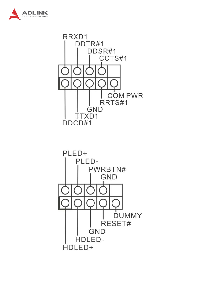
COM3, 4, 5, 6 Headers (9-pin COM3/COM4/COM5/COM6)
2
1
System Panel Header (9-pin PANEL1)
Accommodates multiple front panel system functions.
2
1
18 Getting Started
Page 29

IMB-M42H
Connect the power switch, reset switch and system status
indicator on the chassis to the header as follows. Note positive
and negative pins positions before connecting the cables.
Connect to the power switch on
PWRBTN (Power Switch)
the chassis front panel and
configure as desired.
RESET (Reset Switch)
Connect to the reset switch on
the chassis front panel.
Connect to the power status
indicator on the chassis front
panel. The LED is lit when the
PLED (System Power LED)
system is operating, blinks
when the system is in S1/S3
sleep state, and is unlit when
the system is in S4 sleep state
or powered off (S5).
Connect to the hard drive
HDLED (Hard Drive Activity
LED)
activity LED on the chassis
front panel. The LED is lit when
the hard drive is reading or
writing data.
Table 2-3: Front Panel Connections
While front panel design and layout may differ by chassis, the
panel conventionally has at least a power switch, reset switch,
power LED, hard drive activity LED, and speaker. When
connecting, ensure cable and pin assignments are matched
correctly.
Getting Started 19
Page 30

SATA2 Connectors (SATA_4/SATA_5)
Enable Serial ATA2 data input at up to 3.0 Gb/s.
SATA_4
SATA_5
SATA3 Connectors (SATA_0/SATA_1)
Enable Serial ATA3 data input at up to 6.0 Gb/s.
USB 2.0 Headers (9-pin USB6_7/USB8_9))
PWR
+
GND
6
1
1
GND
+
-
PWR
In addition to the four on the I/O pane l, two
USB 2.0 headers on the board each
support two USB 2.0 ports.
NC
SATA_0
SATA_1
20 Getting Started
Page 31

Chassis Intrusion Headers (2-pin CI1/CI2)
The motherboard supports CASE OPEN
notification if the chassis is equipped with
1
intrusion detection capability.
Signal
Front Panel Audio Header (9-pin HD_AUDIO1)
Provides front audio cable connection.
GND
PRESENCE#
MIC_RET
OUT_RET
6
1
1
OUT2_L
J_SENSE
OUT2_R
MIC2_L
MIC2_R
IMB-M42H
GND
TPM Header (19-pin TPM1)
Supports the Trusted Platform
Module (TPM) system storing
keys, digital certificates,
passwords, and data,
enhancing network security,
protecting digital identity, and
ensuring platform integrity.
SMB_DATA_MAIN
SMB_CLK_MAIN
Getting Started 21
48MHz
GND
SERIRQ#
S_PWRDWN#
GND
LAD1
LAD2
GND
12
1
+5V
GND
+3VSB
LAD0
+3V
LAD3
PCIRST#
FRAME
PCICLK
Page 32

Print Port Header (25-pin LPT1)
Enables convenient front
12
1
+5V
GND
+3VSB
LAD0
+3V
LAD3
PCIRST#
FRAME
PCICLK
panel connection of printer
devices.
48MHz
GND
SERIRQ#
S_PWRDWN#
GND
LAD1
LAD2
SMB_DATA_MAIN
SMB_CLK_MAIN
GND
2.7 Driver Installation
Download the requisite drivers for your system from
http://www.adlinktech.com and install.
22 Getting Started
Page 33

Appendix A - UEFI Setup Utility
A.1 Introduction
This section explains how to use the UEFI Setup Utility to configure your system. The UEFI chip on the motherboard stores the
UEFI Setup Utility. You may run the UEFI Setup Utility when you
start up the computer. Select <F2> or <Del> during the
Power-On-Self-Test (POST) to enter the UEFI Setup Utility, otherwise, POST will continue with its test routines.
To enter the UEFI Setup Utility after POST, restart the system by
pressing <Ctl> + <Alt> + <Delete>, or by pressing the reset button
on the system chassis. You may also restart by turning the system
off and then back on.
Because the UEFI software is frequently updated, the setup
screens and descriptions provided are for reference only, and
NOTE:
NOTE:
A.2 UEFI Menu Bar
The top of the screen has a menu bar with the following selections:
may not conform exactly with those displayed.
IMB-M42H
Main Configures system time/date information
Advanced Sets up advanced UEFI features
H/W Monitor Displays current hardware status
Boot Sets default system device to locate and load OS
Security Sets up security features
Exit Exits the current screen or UEFI Setup Utility
Use arrow keys to choose among the selections on the menu bar,
and select Enter to access the sub screen. The mouse can also be
used to select items
UEFI Setup Utility 23
Page 34

A.3 Navigation Keys
Key(s) Function
R/L Arrow Moves cursor left or right to select Menus
U/D Arrow Moves cursor up or down to select items
+/- Changes option for the selected item
Enter Opens the selected Menu
F1 Displays General Help
F7 Discards changes
F9 Loads default values for all settings
F10 Saves changes and exits Setup
F12 Prints screen
ESC Opens the Exit Menu or exits the current screen
Table A-1: Navigation Key Functions
A.4 Main Menu
When UEFI Setup is started, the Ma in menu appears, displaying
system overview.
24 UEFI Setup Utility
Page 35

A.5 Advanced Menu
IMB-M42H
Accesses CPU Configuration, Chipset Configuration, Storage
Configuration, Intel
®
Smart Connect Technology, Super IO Configuration, ACPI Configuration, USB Configuration, Voltage Configuration and Instant Flash settings.
Incorrect settings in this menu can cause serious malfunction
CAUTION:
Instant Flash
Instant Flash is a UEFI flash utility embedded in Flash ROM. This
convenient UEFI update tool allows you to update system UEFI
without entering operating systems first like MS-DOS or Win-
®
dows
. Just launch this tool and save the new UEFI file to your
USB flash drive, floppy disk or hard drive, then you can update
your UEFI only in a few clicks without preparing an additional
floppy diskette or other complicated flash utility. Please be noted
UEFI Setup Utility 25
Page 36

that the USB flash drive or hard drive must use FAT32/16/12 file
system. If you execute Instant Flash utility, the utility will show the
UEFI files and their respective information. Select the proper UEFI
file to update your UEFI, and reboot your system after UEFI
update process completes.
A.6 CPU Configuration
Active Processor Cores
Selects the number of cores enabled in each processor package.
CPU C States Support
Enables CPU C States Support for power conservation, with C3,
C6 and C7 recommended enabled for best results.
Enhanced Halt State (C1E)
Enables Enhanced Halt State (C1E) for lower power consumption.
26 UEFI Setup Utility
Page 37

IMB-M42H
CPU C3 State Support
Enables C3 sleep state for lower power consumption.
CPU C6 State Support
Enables C6 deep sleep state for lower power consumption.
CPU C7 State Support
Enables C7 deep sleep state for lower power consumption.
Package C State Support
Enables CPU, PCIe, memory, graphics C State Support for power
conservation.
Intel SpeedStep Technology
Intel’s power saving technology, under which processors can
switch between multiple frequencies and voltage points to conseve power saving, with default value Enabled. If you Windows®
7 / 8 is installed, to enableset to Enabled. Hidden if the current
CPU does not support Intel SpeedStep technology.
Intel Turbo Boost Technology
Enables or disables Intel Turbo Boo s t Mo d e, w hic h a llow s pr o c es sor cores to run faster than marked frequency in specific conditions, with default Enabled.
CPU Thermal Throttling
Enables CPU internal thermal control to prevent CPU overheating.
No-Execute Memory Protection
Enhancement to the IA-32 Intel Architecture, preventing data page
use by malicious software to execute codes, hidden if the current
CPU does not support No-Excute Memory Protection.
UEFI Setup Utility 27
Page 38

Intel Virtualization Technology
When enabled, VMM (Virtual Machine Architecture) utilizes additional hardware capabilities provided by Vanderpool Technology,
hidden if the installed CPU does not support Intel Virtualization
Technology.
Hardware Prefetcher
Turns MLC streamer prefetcher on and off.
Adjacent Cache Line Prefetch
Turns prefetching of adjacent cache lines on and off.
A.7 Chipset Configuration
DRAM Frequency
If Auto is selected, installed memory module(s) are detected and
assigned appropriate frequency.
28 UEFI Setup Utility
Page 39

IMB-M42H
Primary Graphics Adapter
Onboard, PCI, or PCI Express can be selected as boot graphic
adapter priority, with default PCI Express.
VT-d
Enables/disables Intel® VT-d technology (Intel® Virtualization
Technology for Directed I/O), with default Disabled.
PCIE1 Link Speed
Selects link speed for PCIE1.
PCIE3 Link Speed
Selects link speed for PCIE3.
Share Memory
Configure the size of memory allocated to the integrated graphics
processor when the system boots.
IGPU Multi-Monitor
Disable deactivates integrated graphics when an external gra phics
card is installed, Enable maintains integrated graphics function at
all times.
Render Standby
Enables/disables Render Standby by Internal Graphics Device,
default is Enabled.
Onboard HD Audio
Auto disables onboard HD Audio when a PCI Sound Card is
installed.
Front Panel
Auto enables or disables onboard Front Panel HD Audio.
UEFI Setup Utility 29
Page 40

Onboard HDMI HD Audio
Enables/disables onboard HDMI HD Audio.
Onboard LAN
Enables/disables onboard LAN feature.
Restore on AC/Power Loss
Sets power resume state after AC power loss, with Power Off
maintaining power off on resume, Power On booting the system
upon resume.
A.8 Storage Configuration
SATA Controller(s)
Enables/disables SATA Controller.
30 UEFI Setup Utility
Page 41

IMB-M42H
SATA Mode Selection
Selects SATA mode, from IDE, AHCI (default), and Disabled.
AHCI (Advanced Host Controller Interface) supports NCQ and
other features to improve SATA disk performance, IDE mode does
not.
SATA Aggressive Link Power Mgmt
Configures SATA Aggressive Link Power Management.
Hard Disk S.M.A.R.T.
Enables/disables S.M.A.R.T. (Self-Monitoring, Analysis, and
Reporting Technology) feature.
A.9 Intel® Smart Connect Technology
Enables/disables Intel® Smart Connect Technology, for
auto-updates of email and social network applications, while in
sleep mode, with default is Enabled.
UEFI Setup Utility 31
Page 42

A.10 Super IO Configuration
COM1 Configuration
Sets parameters for COM1, from port type [RS232], [RS422] or
[RS485].
COM2 Configuration
Sets parameters for COM2, from port type [RS232], [RS422] or
[RS485].
COM3 Configuration
Sets parameters for COM3.
COM4 Configuration
Sets parameters for COM4.
32 UEFI Setup Utility
Page 43

IMB-M42H
COM5 Configuration
Sets parameters for COM5.
COM6 Configuration
Sets parameters for COM6.
LPT1 Port Configuration
Sets parameters for the onboard parallel port.
WDT Timeout Reset
Enables/disables Watch Dog Timer timeout to reset system, with
default Disabled.
A.1 1 ACPI Configuration
UEFI Setup Utility 33
Page 44

Suspend to RAM
Selects auto-detect or disable for Suspend-to-RAM, with default of
Auto, if OS supports.
Check Ready Bit
Enables/disables Check Ready Bit.
ACPI HPET Table
Enables/disables ACPI HPET Table, with default Enab led, to be
set when Windows
®
certification is to be submitted.
PS/2 Keyboard Power On
Enables/disables PS/2 keyboard power on when in power-soft-off
mode.
PCI Devices Power On
Enables/disables PCI device power on from power-soft-off mode.
Wake From Onboard LAN
Enables/disables Wake From Onboard LAN.
RTC Alarm Power On
Enables/disables RTC (Real Time Clock) power on.
USB Keyboard/Remote Power On
Enables/disables USB keyboard/remote power on.
USB Mouse Power On
Enables/disables USB mouse power on.
34 UEFI Setup Utility
Page 45

A.12 USB Configuration
IMB-M42H
USB Controller
Enables/disables the USB controller.
Intel USB 3.0 Mode
Enables/disables Intel USB 3.0 mode.
Legacy USB Support
Selects legacy support for USB devices, from default Enabled,
supporting legacy USB, Auto, supporting legacy USB when
devices are connected, and Disabled (if USB compatibility issues
occur, it is recommended to select Disabled to enter OS), and
UEFI Setup Only, in which USB devices are allowed only under
UEFI setup and Windows/Linux OS.
UEFI Setup Utility 35
Page 46

Legacy USB 3.0 Support
Enables/disables legacy support for USB 3.0 devices, with default
Enabled.
A.13 Voltage Configuration
Selects DRAM Voltage, with default 1.50V.
36 UEFI Setup Utility
Page 47

A.14 Hardware Health Event Monitoring
IMB-M42H
In addition to monitoring current CPU, fan(s), and voltage status,
the following settings can be configured.
CPU_FAN1 & 2 Setting
Sets speed for CPU fans 1 & 2, from Full On (default) and Automatic.
CHA_FAN1 & 2 Setting
Sets speed for chassis fans 1 & 2, from Full On (default) and Automatic.
Over Temperature Protection
Enables/disables Over Temperature Protection, with default
Enabled.
UEFI Setup Utility 37
Page 48

Case Open Feature
Enables/disables case open detection with default Disabled.
Clear Status
Appears only when a case opening has been detected. Clears the
record of previous chassis intrusion notifications.
A.15 Boot
Boot From Onboard LAN
Enables/disables Boot From Onboard LAN.
Setup Prompt Timeout
Displays the number of seconds to wait for setup activation key,
with 65535(0XFFFF) indicating indefinite wait.
38 UEFI Setup Utility
Page 49

IMB-M42H
Bootup Num-Lock
When set to [On], automatically activates Num Lock keypad following boot.
Boot Beep
Enables/disables Boot Beep, available only when a chassis
buzzer is installed.
Full Screen Logo
Enables/disables OEM Logo, with default Enabled.
CSM
Must be disabled when Fast Boot is enabled, with default Enabled.
When Enabled, opens CSM submenu.
UEFI Setup Utility 39
Page 50

Enable to launch the Compatibility Support Module. Only disable
when running a WHCK test. If OS is Window s® 8 64-bit and all
devices support UEFI, CSM can be disabled for faster boot.
Launch PXE OpROM Policy
Enables UEFI to run those devices that support UEFI option ROM
only. Selecting Legacy enables only devices that support legacy
option ROM only.
Launch Storage OpROM Policy
Enables UEFI to run those devices that support UEFI option ROM
only. Selecting Legacy enables only devices that support legacy
option ROM only.
Launch Video OpROM Policy
Enables UEFI to run those devices that support UEFI option ROM
only. Selecting Legacy enables only devices that support legacy
option ROM only.
40 UEFI Setup Utility
Page 51

IMB-M42H
A.16 Security
In addition to setting, changing, or clearing supervisor/user password for the system, this menu provides the following settings.
Secure Boot
Enables/Disables Secure Boot, with default Disabled.
UEFI Setup Utility 41
Page 52

A.17 Exit
Save Changes and Exit
Generates confirmation prompt. Selecting OK saves changes and
exits.
Discard Changes and Exit
Generates confirmation prompt. Select ing OK exits with out saving
any changes.
Discard Changes
Generates confirmation prompt. Selecting OK discards all
changes.
42 UEFI Setup Utility
Page 53

IMB-M42H
Important Safety Instructions
For user safety, please read and follow all instructions,
WARNINGS, CAUTIONS, and NOTES marked in this manual
and on the associated equipment before handling/operating the
equipment.
X Read these safety instructions carefully.
X Keep this user’s manual for future reference.
X Read the specifications section of this manual for detailed
information on the operating environment of this equipment.
X When installing/mounting or uninstalling/removing
equipment:
Z Turn off power and u nplug any power cords/cables.
X To avoid electrical shock and/or damage to equipment:
Z Keep equipment away from water or liquid sources;
Z Keep equipment away from high heat or high humidity;
Z Keep equipment properly ventilated (do not block or
cover ventilation openings);
Z Make sure to use recommended voltage and powe r
source settings;
Z Always install and operate equipment near an easily
accessible electrical socket-outlet;
Z Secure the power cord (do not place any obje ct on /ove r
the power cord);
Z Only install/attach and operate equipment on stable
surfaces and/or recommended mountings; and,
Z If the equipment will not be used for long periods of time,
turn off and unplug the equipment from its power source.
Important Safety Instructions 43
Page 54

X Never attempt to fix the equipment. Equipmen t sho u ld on ly
be serviced by qualified personnel.
A Lithium-type battery may be provided for uninterrupted, backup
or emergency power.
Risk of explosion if battery is replaced with one of an incorrect
WARNING:
type. Dispose of used batteries appropriately.
X Equipment must be serviced by authorized technicians
when:
Z The power cord or plug is damaged;
Z Liquid has penetrated the equipment;
Z It has been exposed to high humidity/moisture;
Z It is not functioning or does not function according to the
user’s manual;
Z It has been dropped and/or damaged; and/or,
Z It has an obvious sign of breakage.
44 Important Safety Instructions
Page 55

Getting Service
Contact us should you require any service or assistance.
ADLINK Technology, Inc.
Address: 9F, No.166 Jian Yi Road, Zhonghe District
New Taipei City 235, Taiwan
ᄅקؑխࡉ৬ԫሁ 166 ᇆ 9 ᑔ
Tel: +886-2-8226-5877
Fax: +886-2-8226-5717
Email: service@adlinktech.com
Ampro ADLINK Technology, Inc.
Address: 5215 Hellyer Avenue, #110
San Jose, CA 95138, USA
Tel: +1-408-360-0200
Toll Free: +1-800-966-5200 (USA only)
Fax: +1-408-360-0222
Email: info@adlinktech.com
ADLINK Technology (China) Co., Ltd.
Address: Ϟ⍋Ꮦ⌺ϰᮄᓴ∳催⾥ᡔು㢇䏃 300 ো(201203)
300 Fang Chun Rd., Zhangjiang Hi-Tech Park
Pudong New Area, Shanghai, 201203 China
Tel: +86-21-5132-8988
Fax: +86-21-5132-3588
Email: market@adlinktech.com
IMB-M42H
ADLINK Technology Beijing
Address: ࣫ҀᏖ⍋⎔Ϟഄϰ䏃 1 োⲜ߯ࡼ E ᑻ 801 ᅸ(100085)
Beijing, 100085 China
Tel: +86-10-5885-8666
Fax: +86-10-5885-8626
Email: market@adlinktech.com
ADLINK Technology Shenzhen
Address: ⏅ഇᏖቅ⾥ᡔು催ᮄϗ䘧᭄ᄫᡔᴃು
Tel: +86-755-2643-4858
Fax: +86-755-2664-6353
Email: market@adlinktech.com
LiPPERT ADLINK Technology GmbH
Address: Hans-Thoma-Strasse 11, D-68163
Mannheim, Germany
Tel: +49-621-43214-0
Fax: +49-621 43214-30
Email: emea@adlinktech.com
Rm. 801, Power Creative E, No. 1 Shang Di East Rd.
A1 2 ὐ C (518057)
2F, C Block, Bldg. A1, Cyber-Tech Zone, Gao Xin Ave. Sec. 7
High-Tech Industrial Park S., Shenzhen, 518054 China
Getting Service 45
Page 56

ADLINK Technology, Inc. (French Liaison Office)
Address: 6 allée de Londres, Immeuble Ceylan
91940 Les Ulis, France
Tel: +33 (0) 1 60 12 35 66
Fax: +33 (0) 1 60 12 35 66
Email: france@adlinktech.com
ADLINK Technology Japan Corporation
Address: ͱ101-0045 ᵅҀ䛑ҷ⬄⼲⬄䤯ފ⬎ 3-7-4
Tel: +81-3-4455-3722
Fax: +81-3-5209-6013
Email: japan@adlinktech.com
ADLINK Technology, Inc. (Korean Liaison Office)
Address: 137-881 昢殾柢 昢爎割 昢爎堆嵢 326, 802 (昢爎壟, 微汾瘶捒娯)
Tel: +82-2-2057-0565
Fax: +82-2-2057-0563
Email: korea@adlinktech.com
ADLINK Technology Singapore Pte. Ltd.
Address: 84 Genting Lane #07-02A, Cityneon Design Centre
Tel: +65-6844-2261
Fax: +65-6844-2263
Email: singapore@adlinktech.com
⼲⬄ 374 ɛɳ 4F
KANDA374 Bldg. 4F, 3-7-4 Kanda Kajicho,
Chiyoda-ku, Tokyo 101-0045, Japan
802, Mointer B/D, 326 Seocho-daero, Seocho-Gu,
Seoul 137-881, Korea
Singapore 349584
ADLINK Technology Singapore Pte. Ltd. (Indian Liaison Office)
Address: #50-56, First Floor, Spearhead Towers
Malleswaram, Bangalore - 560 055, India
Tel: +91-80-65605817, +91-80-42246107
Fax: +91-80-23464606
Email: india@adlinktech.com
ADLINK Technology, Inc. (Israeli Liaison Office)
Address: 27 Maskit St., Corex Building
PO Box 12777
Herzliya 4673300, Israel
Tel: +972-77-208-0230
Fax: +972-77-208-0230
Email: israel@adlinktech.com
ADLINK Technology, Inc. (UK Liaison Office)
Tel: +44 774 010 59 65
Email: UK@adlinktech.com
Margosa Main Road (between 16th/17th Cross)
46 Getting Service
 Loading...