

Page 1
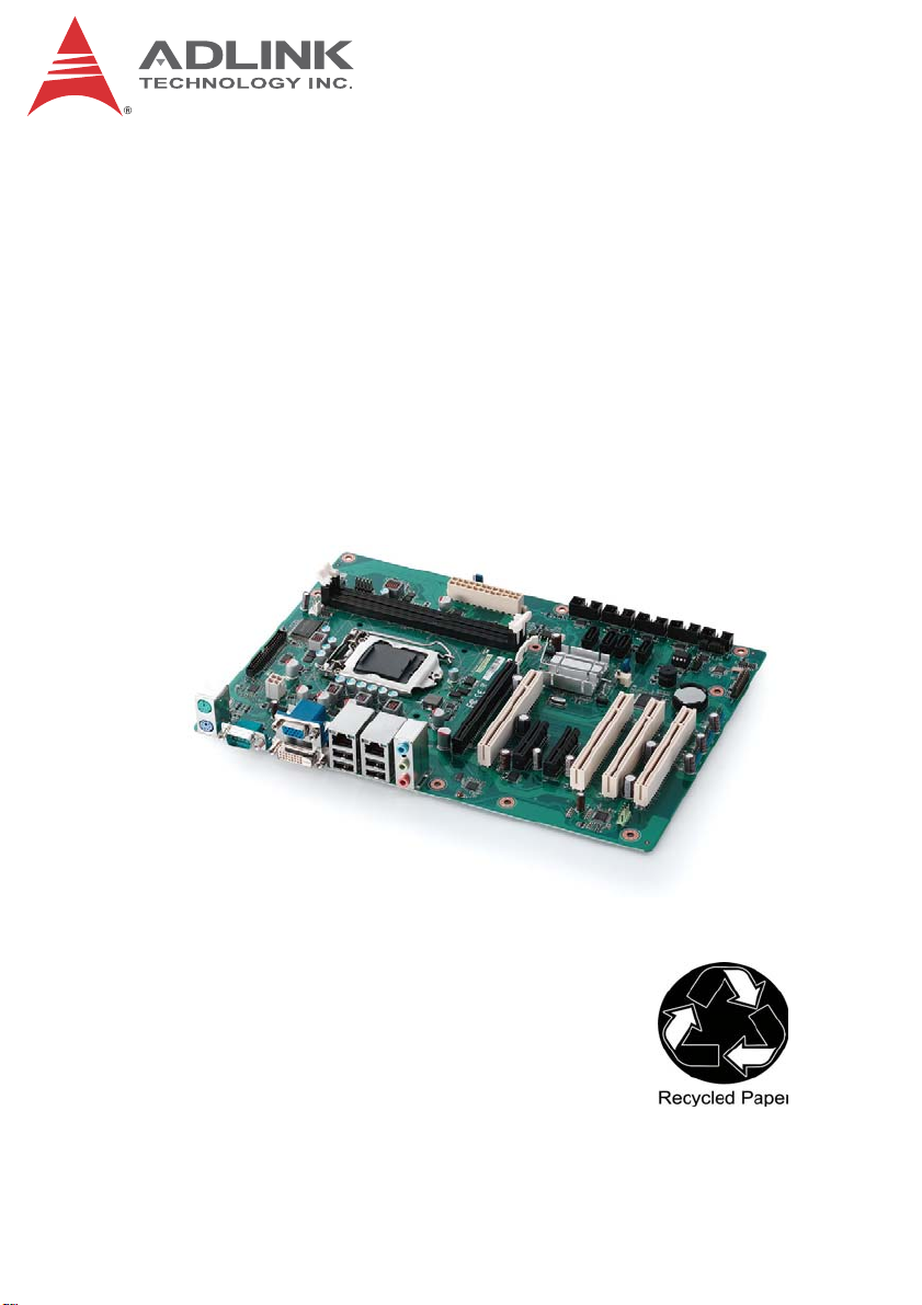
IMB-M40H
ATX Intel® Core™ i7/i5/i3
Industrial Motherboard
User’s Manual
Manual Rev.: 1.00
Revision Date: July 31, 2013
Part No: 50-1X005-1000
Advance Technologies; Automate the World.
Page 2

Revision History
Revision Release Date Description of Change(s)
1.00 2013/7/31 Preliminary release
ii Revision History
Page 3

IMB-M40H
Preface
Copyright 2013 ADLINK Technology, Inc.
This document contains proprietary infor mation protected by copyright. All rights are reserved. No part of this manual may be reproduced by any mechanical, electronic, or other means in any form
without prior written permission of the manufacturer.
Disclaimer
The information in this document is subject to change without prior
notice in order to improve reliability, design, and function and does
not represent a commitment on the part of the manufa cturer.
In no event will the manufacturer be liable for direct, indirect, special, incidental, or consequential damages arising out of the use or
inability to use the product or documentation, even if advised of
the possibility of such damages.
Environmental Responsibility
ADLINK is committed to fulfill its social responsibility to global
environmental preservation through compliance with the European Union's Restriction of Hazardous Substances (RoHS) directive and Waste Electrical and Electronic Equipment (WEEE)
directive. Environmental protection is a top priority for ADLINK.
We have enforced measures to ensure that our products, manufacturing processes, components, and raw materials have as little
impact on the environment as possible. When products are at their
end of life, our customers are encouraged to dispose of them in
accordance with the product disposal and/or recovery programs
prescribed by their nation or company.
Trademarks
Product names mentioned herein are used for identification purposes only and may be trademarks and/or registered trademarks
of their respective companies.
Preface iii
Page 4

Using this Manual
Audience and Scope
The IMB-M40H User’s Manual is intended for hardware
technicians and systems operators with knowledge of installing,
configuring and operating industrial grade systems.
Manual Organization
This manual is organized as follows:
Preface: Presents important copyright notifications, disclaimers,
trademarks, and associated information on the proper under st anding and usage of this document and its associated product(s).
Chapter 1, Introduction: Introduces the IMB-M40H, its features,
applications, and specifications, including functional descriptions
and board layout.
Chapter 2, Hardware Information: Provides technical information on connectors and jumpers for configuring the IMB-M40H.
Chapter 3, Getting Started: Illustrates how to install components
on the IMB-M40H such as CPU, heatsink, and memory modules.
Chapter 4, Driver Installation: Provides information on how to
install the IMB-M40H device drivers.
Important Safety Instructions: Presents safety instructions all
users must follow for the proper setup, installation and usage of
equipment and/or software.
Getting Service: Contact information for ADLINK’s worldwide
offices.
iv Preface
Page 5
IMB-M40H
Conventions
Take note of the following conventions used throughout this
manual to make sure that users perform certain tasks and
instructions properly.
Additional information, aids, and tips that help users perform
tasks.
NOTE:
NOTE:
Information to prevent minor physical injury, component damage, data loss, and/or program corruption when trying to com-
CAUTION:
WARNING:
plete a task.
Information to prevent serious physical injury, component
damage, data loss, and/or program corruption when trying to
complete a specific task.
Preface v
Page 6

This page intentionally left blank.
vi Preface
Page 7

IMB-M40H
Table of Contents
Revision History...................................................................... ii
Preface.................................................................................... iii
List of Figures........................................................................ ix
List of Tables.......................................................................... xi
1 Introduction ........................................................................ 1
1.1 Overview.............................................................................. 1
1.2 Features............................................................................... 2
1.3 Specifications....................................................................... 3
1.4 Block Diagram ..................................................................... 5
1.5 Functional Description ......................................................... 6
1.6 Power Consumption ............................ ... ... ... ... .... ... ... ... .... ... 8
1.7 Mechanical Drawings......................................................... 11
1.8 Package Contents ............................................................. 12
2 Hardware Information...................................................... 13
2.1 Rear I/O Connectors.......................................................... 13
2.2 Board Layout ..................................................................... 17
2.3 Onboard Connectors & Jumpers....................................... 19
2.4 Jumpers............................................................................. 24
3 Getting Started ................................................................. 27
3.1 Installing the CPU.............................................................. 27
3.2 Installing the CPU Fan and Heatsink................................. 31
3.3 Installing Memory Modules................................................ 32
4 Driver Installation............................................................. 35
Table of Contents vii
Page 8

Important Safety Instructions............................................... 37
Getting Service...................................................................... 39
viii Table of Contents
Page 9

IMB-M40H
List of Figures
Figure 1-1: IMB-M40H Block Diagram ...............................................5
Figure 1-2: IMB-M40H Board Dimensions ....................................... 11
Figure 2-1: IMB-M40H Rear I/O Layout ........................................... 13
Figure 2-2: IMB-M40H Board Layout ............................................... 17
List of Figures ix
Page 10

This page intentionally left blank.
xList of Figures
Page 11

IMB-M40H
List of Tables
Table 1-1: IMB-M40H General Specifications...................................3
Table 1-2: Core™ i7-3770 Power Consumption............................... 8
Table 1-3: Core™ i3-3220 Power Consumption............................... 9
Table 1-4: Pentium® G2120 Power Consumption..........................10
Table 2-1: IMB-M40H Board Layout Legend.................................. 18
List of Tables xi
Page 12

This page intentionally left blank.
xii List of Tables
Page 13

1 Introduction
1.1 Overview
The ADLINK IMB-M40H is an ATX industrial motherboard
supporting the 3rd Generation Intel® Core™ i7/i5/i3 and Pentium®
processors in LGA1155 package to deliver a scalable high
performance platform for a wide array of industrial applications.
The IMB-M40H supports 22nm process CPUs at up to 3.4 GHz
with integrated graphics and memory controllers, Direct Media
Interface (DMI) and Flexible Display Interface (FDI) connectivity to
the Intel® H61 Express Chipset. Dual-channel DDR3 1333/1600
MHz memory is supported up to a maximum of 16 GB in two
DIMM slots.
These advanced features, coupled with integrated graphics, one
PCI Express x16 slot, two PCI Express x1 slots, four PCI slots,
dual PCI Express-based Gigabit Ethernet, SATA 3 Gb/s and audio
interfaces make the IMB-M40H ideal for automation control, medical, test & measurement, and telecom applications requiring a
high-performance, easy-to-deploy and reliable mainboard.
IMB-M40H
Introduction 1
Page 14

1.2 Features
X ATX form factor (305 mm x 218 mm)
X Supports 3rd Generation Intel® Core™ i7/i5/i3 and Pen-
tium® processors in LGA1155 package
X Integrated Intel® HD Graphics
X One PCIe x16 slot, two PCIe x4 slots (with PCIe x1 signals),
four PCI slots
X Dual Gigabit Ethernet
X 10x USB 2.0 ports (6x onboard, 4x on faceplate)
X 4x SATA 3 Gb/s ports
X VGA, DVI-D
X 5x RS-232 + 1x RS-232/422/485
X Watchdog Timer, Hardware Moni tor
X Realtek ALC892 HD audio codec
X 16in+16out DIO
X 2x Mini-DIN for PS/2 keyboard/mouse
X RoHS compliant
2Introduction
Page 15
1.3 Specifications
System
Intel® Core™ (LGA115)
• Intel® Core™ i7-3770, 3.40 GHz, 8M Cache, 22nm, 77W TDP (4C)
• Intel® Core™ i5-3550S, 3.0 GHz, 6M Cache, 22nm, 65W TDP (4C)
CPU
Chipset Intel® H61 Express Chipset
Memory
BIOS AMIBIOS in 32-Mbit SPI Flash
Audio
Watch Dog
Timer
Hardware
Monitor
Operating
Systems
Serial ATA • 4x SATA 3 Gb/s ports
Onboard I/O • 3x USB 2.0 pin headers (6 ports)
Rear I/O • 2x Gigabit Ethernet RJ45 ports
• Intel® Core™ i3-3220, 3.30 GHz, 3M Cache, 22nm, 55W TDP (2C)
•Intel® Pentium® G2120, 3.10 GHz, 3M Cache, 22nm, 55W TDP (2C)
• Intel® Celeron® G1620, 2.7 GHz, 2M Cache, 22nm, 55W TDP (2C)
• Intel® Celeron® G540, 2.5 GHz, 2M Cache, 32nm, 65W TDP (2C)
®
• Intel
2x 240-pin DIMM sockets
Dual-channel DDR3 1333/1600 MHz (up to 16 GB)
Realtek ALC892 HD codec
Supports line-in, line-out and mic-in
1-255 second or 1-255 minute programmable and can generate
system reset.
CPU/System temperature, CPU fan speed and onboard DC
voltage
• Windows XP, 7, 32/64-bit
• Fedora 17
• Red Hat Enterprise Linux 6.2
• 5x RS-232 + 1x RS-232/422/485 (COM6)
• 16in+16out DIO ports
• 1x front panel pin header
• 4x USB 2.0 ports
• 1x VGA connector
•1x DVI-D port
• 2x PS2 keyboard/mouse ports
• 3x audio jacks (line-in, line-out and mic-in)
Table 1-1: IMB-M40H General Specifications
Pentium® Dual Core G850, 2.9 GHz, 3M Cache, 32nm, 65W
TDP (2C)
I/O Interfaces
IMB-M40H
Introduction 3
Page 16
Expansion Slots • 1x PCIe-x16 Gen 2
• 2x PCIe x4 slot (with PCIe x1 signal)
• 4x PCI slots
Display
Graphics Integrated Intel® HD Graphics
VGA Dsub-15 connector, up to 2048x1536 @ 75 Hz
DVI-D DVI-D connector, up to 1920x 1200 @ 60 Hz
Ethernet
• Dual Gigabit Ethernet (Realtek® 8111E Gigabit Ethernet
Controller
Ports Two RJ-45 Ethernet ports
Form Factor ATX Industrial Motherboard
Dimensions 305 mm x 218 mm (L x W)
Operating Temp. 0ºC to 60ºC
Storage Temp. -20ºC to 80ºC
Rel. Humidity 10% to 90% non-condensing
Safety CE, FCC Class A
Controller)
• Supports Preboot Execution Environment (PXE),
Wake-On-LAN
Mechanical and Environment
Table 1-1: IMB-M40H General Specifications
4Introduction
Page 17

1.4 Block Diagram
IMB-M40H
PCIe x16 Gen 2.0
for Discrete Graphic
VGA
DVI-D
10 USB 2.0 Ports
4 SATA Ports
at 3.0Gb/s
Realtek
HD Audio
HD Audio
ALC892
Dual Channel
3rd Gen Intel
3rd Gen Intel
Core i7/i5/i3
Core i7/i5/i3
dual/quad core
dual/quad core
32/22nm
32/22nm
x2 Display Link
SPI
DIO17-32
DIO1-16
BIOS
Intel
Intel
H61
H61
PCH
PCH
SM
Bus
x4 DMI
GPIO
Expansion
DDR3 1333/1600
PCIe to
Realtek
KB/MS
PCI
Bridge
8111E
Super I/O
NCT6776F
Figure 1-1: IMB-M40H Block Diagram
Max. 16GB
2 PCIe x4 slots
w/ PCIe x1 signal
Realtek
8111E
Nuvoton
COM1-2
4 PCI slots
Dual
GbE
Fintek
81216AD
COM3-6
Introduction 5
Page 18

1.5 Functional Description
Processor Support
The IMB-M40H is an industrial motherboard supporting the 3rd
generation Intel® Core™ processor family (Intel® Core™ i7/i5/i3)
in LGA1155 socket. An integrated memory controller supports
dual channel DDR3 1333/1600 MHz and Intel® HD Graphics is
integrated onboard the CPU. The CPU provides a PCI Express
x16 for external graphics or expansion. Direct Media Interface
(DMI) and Flexible Display Interface (FDI) provide connectivity to
the Intel® H61 Express Chipset.
Intel® H61 Express Chipset
The Intel® BD82H61 Platform Controller Hub (PCH) combines
with the processor to provide a compact yet powerful 2-chip solution. Direct Media Interface (DMI) is the chip-to-chip connection
between the processor and PCH. Intel® Flexible Display Interface
carries display traffic from the integrated graphics in the processor
to the legacy display connectors in the PCH. The PCH supports all
other required interfaces including PCI Express, SATA 3 Gb/s,
USB 2.0, PCI, LPC, and SPI.
Dual-Channel DDR3 Memory
To meet the requirements of memory-intensive applications, the
IMB-M40H has a dual-channel memory architecture supporting
DDR3 1333/1600 MHz DIMMs. The key advantages of DDR3 are
the higher bandwidth and the increase in performance at lower
power than DDR2. DDR3 memory technology meets the requirements of the latest 3D graphics, multimedia, and network application, and boosts system performance by eliminating bottlenecks.
Gigabit Ethernet
The IMB-M40H utilizes two Realtek® RTL8111E Gigabit Ethernet
Controllers connected to the PCI-E bus of the H61 PCH.
Wake-on-LAN and PXE are supported.
6Introduction
Page 19

IMB-M40H
Serial ATA
The IMB-M40H provides four SATA 3 GB/s ports.
Hardware monitoring
A built-in, proactive hardware monitoring system in the Super I/O
monitors the CPU temperature, CPU fan speed, and voltage levels
to prevent overheating and/or component damage, effect timely
failure detection, and ensure stable supply of current for critical
components.
Watchdog Timer
The watchdog timer (WDT) monitors system operations based on
user-defined configurations. The WDT can be programmed for different time-out periods, such as from 1 to 255 seconds or from 1 to
255 minutes. The WDT generates a reset signal, then a reset
request, after failure to strobe it within the programmed time
period. A register bit may be enabled to indicate if the watchdog
timer caused the reset event. The WDT register is cleared during
the power-on sequence to enable the operating system to take
appropriate action when the watchdog generates a reboot.
Introduction 7
Page 20

1.6 Power Consumption
T e st Con f ig uration
Memory
Graphics Intel® Graphics Media Accelerator HD (integrated)
Storage Seagate ST9160412AS Momentus 7200.4 160GB
Power Supply Sunpower SPX-6500P1 500W
Intel® Core™ i7-3770 Processor (8M Cache, 3.40 GHz)
Power Req. +5V +12V +3.3V Total
Current (A) 0.64 1.04 0.46 —
Power (W) 3.2 12.48 1.52 17.20
Power Req. +5V +12V +3.3V Total
Current (A) 1.32 0.59 0.50 —
Power (W) 6.6 7.08 1.65 15.33
Power Req. +5V +12V +3.3V Total
Current (A) 1.35 8.00 0.82 —
Power (W) 6.75 96.0 2.71 105.45
Power Req. +5V +12V +3.3V Total
Current (A) 1.76 7.41 0.65 —
Power (W) 8.8 88.92 2.14 99.86
2x Transcend 8GB DDR3 1600 DIMM
(CL11 SEC K4B4G0846B-HYK0 8GB)
S1
Idle Load
CPU Max
Max. Load
T able 1-2: Core™ i7-3770 Power Consumption
8Introduction
Page 21

IMB-M40H
Intel® Core™ i3-3220 Processor (3M Cache, 3.30 GHz)
S1
Power Req. +5V +12V +3.3V Total
Current (A) 0.64 0.92 0.38 —
Power (W) 3.2 11.04 1.25 15.49
Idle Load
Power Req. +5V +12V +3.3V Total
Current (A) 1.15 0.56 0.50 —
Power (W) 5.75 6.72 1.65 14.12
CPU Max
Power Req. +5V +12V +3.3V Total
Current (A) 1.20 3.24 0.73 —
Power (W) 6.0 38.88 2.41 47.29
Max. Load
Power Req. +5V +12V +3.3V Total
Current (A) 2.13 2.74 0.72 —
Power (W) 10.65 32.88 2.37 45.90
Table 1-3: Core™ i3-3220 Power Consumption
Introduction 9
Page 22

Intel® Pentium® Processor G2120 (3M Cache, 3.10 GHz)
S1
Power Req. +5V +12V +3.3V Total
Current (A) 0.64 0.72 0.38 —
Power (W) 3.2 8.64 1.25 13.09
Idle Load
Power Req. +5V +12V +3.3V Total
Current (A) 1.21 0.57 0.48 —
Power (W) 6.05 6.84 1.58 14.47
CPU Max
Power Req. +5V +12V +3.3V Total
Current (A) 1.23 2.72 0.55 —
Power (W) 6.15 32.64 1.81 40.60
Max. Load
Power Req. +5V +12V +3.3V Total
Current (A) 1.85 2.30 0.73 —
Power (W) 9.25 27.6 2.41 39.26
T able 1-4: Pentium® G2120 Power Consumption
10 Introduction
Page 23

1.7 Mechanical Drawings
IMB-M40H
Dimensions in mm
Figure 1-2: IMB-M40H Board Dimensions
Introduction 11
Page 24

1.8 Package Contents
Before unpacking, check the shipping carton for any damage. If
the shipping carton and/or contents are damaged, inform your
dealer immediately. Retain the shipping carton and packing
materials for inspection. Obtain authorization from the dealer
before returning any product to ADLINK.
X IMB-M40H ATX Industrial Motherboard
X I/O shield
X SATA cable x2
X Driver DVD
X Quick Reference Guide
The IMB-M40H must be protected from static discharge and
physical shock. Never remove any of the socketed parts except
WARNING:
at a static-free workstation. Use the anti-static bag shipped with
the product to handle the board. Wear a grounded wrist strap
when installing and/or servicing.
12 Introduction
Page 25

2 Hardware Information
2.1 Rear I/O Connectors
ʳ
ʳ
VGA
IMB-M40H
LAN
KB/MS COM1
Figure 2-1: IMB-M40H Rear I/O Layout
PS/2 Mouse Port (green)
Pin # Signal Function
1MSDATAMouse Data
2 NC not connected
3 GND Ground
4+5V Power
5 CLK Clock
6 NC not connected
PS/2 Keyboard Port (purple)
Pin # Signal Function
1 KBDA TA Keyboard Data
2 NC not connected
3 GND Ground
4+5V Power
5 CLK Clock
6 NC not connected
USB Audio DVI-D
Hardware Information 13
Page 26

Serial Port Connector (COM1)
Pin # RS-232
1 DCD, Data Carrier Detect
2 RXD, Receive Data
3 TXD, Transmit Data
4 DTR, Data Terminal Ready
5 GND, ground
6 DSR, Data Set Ready
7 RTS, Request to Send
8 CTS, Clear to Send
9 RI, Ring Indicator
DVI-D Connector
Pin # Signal Pin # Signal
1 TMDS Data2- 16 Hot Plug Detect
2 TMDS Data2+ 17 TMDS Data03 TMDS Data2 Shield 18 TMDS Data0+
4 NC 19 TMDS Data0 Shield
5NC20NC
6 DDC Clock 21 NC
7 DDC Data 22 GND
8 NC 23 TMDS Clock Shield
9 TMDS Data1- 24 TMDS Clock +
10 TMDS Data1+ C1 NC
11 TMDS Data1 Shield C2 NC
12 NC C3 NC
13 NC C4 NC
14 P5V C5 GND
15 GND
14 Hardware Information
Page 27

IMB-M40H
VGA Connector.
Signal Name Pin # Pin # Signal Name
Red 1 2 Green
Blue 3 4 VCC pull-up
GND 5 6 GND
GND 7 8 GND
VCC 9 10 GND
VCC pull-up 11 12 DDC2B DATA
HSYNC 13 14 VSYNC
DDC2B CLK 15
LAN Port (RJ-45)
Refer to the tables below for the LAN port pin and LED definitions.
Pin #
1 TX+ BI_DA+
2 TX- BI_DA3 RX+ BI_DB+
4 -- BI_DC+
5-- BI_DC6 RX- BI_DB7 -- BI_DD+
8-- BI_DD-
Orange Linked Orange 100 Mb connection
Blinking Data Activity Green 1 Gb connection
10BASE-T/
100BASE-TX
LED1 (Activity/Link) LED2 (Speed)
Status Description Status Description
Off No Link Off 10 Mb connection
1000BASE-T
LED2
LED1
18
Hardware Information 15
Page 28

USB Connectors
Pin # Signal Name
1Vcc
2 USB3 USB+
4GND
Audio I/O port
The three-jack audio I/O supports Line-In, Line-Out, and Mic-In
functions. The blue Line-In jack connects to an audio source such
as a CD player. The green Line-Out port connects to a speaker or
headphone, while the pink Mic-In jack connects to a microphone.
16 Hardware Information
Page 29

2.2 Board Layout
IMB-M40H
ATX12V1
SYS_FAN
PCIEX16_1
PCI1
PCIEX1_1
PCIEX1_2
PCI2
JDIO1
CPU_FAN
CLRTC1
DIMM_A1
DIMM_B1
JLPC1
PSON1
EATXPWR1
SATA1
SATA3
SATA4 SATA2
PCI3
AAFP1
PCI4
USB78 USB910 USB56
SPI_CN1
JSETCOM6
F_PANEL
Figure 2-2: IMB-M40H Board Layout
Hardware Information 17
COM6 COM5 COM4 COM3 COM2
Page 30

AAFP1 Front Panel Audio Header
ATX12V1 ATX 12V Power Connector
DIMM_A1/B1 240-pin DIMM slots
EA TXPWR1 ATX Power Connector
CLRTC1 Clear CMOS Jumper
COM2~6 Serial Port Connectors 2~6
CPU_FAN CPU Fan Connector
F_PANEL System Panel Pin Header
JDIO1 Digital IO Connector
JLPC LPC Pin Header
JSETCOM6 COM6 Mode Jumpers
PCIEX1_1/2 PCI Express x1 slots
PCIEX16_1 PCI Express x16 slot
PCI1~4 PCI slots
PSON1 AT/ATX Mode Jumper
SATA1~4 SATA 3 Gb/s Connector
SPI_CN1 SPI Pin Header
SYS _FAN System Fan Connector
USB56/78/910 USB 2.0 Pin Headers
Table 2-1: IMB-M40H Board Layout Legend
18 Hardware Information
Page 31

2.3 Onboard Connectors & Jumpers
Front Panel Audio Pin Header (AAFP1)
Pin # Signal Pin # Signal
1 MIC2_L 2 AGND
3 MIC2_R 4 FP_PRES#
5 LIN2_R 6 SRTN1
7 SENSE A 8 NC
9 LIN2_L 10 SRTN2
ATX 12V Power Connector (ATX12V1)
Pin # Signal
1 GND
2 GND
3 +12V DC
4 +12V DC
ATX Power Connector (EATXPWR1)
2
4
IMB-M40H
21
1
3
Pin # Signal Pin # Signal
1 +3.3V 13 +3.3V
12
24
2 +3.3V 14 -12V
3 GND 15 GND
4 +5V 16 PS-ON#
5 GND 17 GND
6 +5V 18 GND
7 GND 19 GND
8 PWRGD 20 NC
9 +5VSB 21 +5V
10 +12V 22 +5V
11 +12V 23 +5V
1
13
12 +3.3V 24 GND
Hardware Information 19
Page 32

Serial Port Connectors - RS-232 (COM2~6)
Pin # Signal Function
1 DCD Data Carrier Detect
2 DSR Data Set Ready
3 RXD Receive Data
4 RTS Request to Send
5 TXD Transmit Data
6 CTS Clear to Send
7 DTR Data Terminal Ready
8 RI Ring Indicate
9 GND Ground
10 NC Key
Serial Port Connector - RS-422/485 (COM6)
Pin # RS-422 RS-485
1TX- DATA2N/A N/A
3TX+ DATA+
4N/A N/A
5RX+ N/A
6N/A N/A
7RX- N/A
8N/A N/A
9GND GND
10 Key Key
12
910
12
910
See "COM6 Mode Jumper Settings (JSETCOM6)" on page 24.
20 Hardware Information
Page 33

CPU Fan Connector (CPU__FAN)
Pin # Signal
1GND
2 Fan power (+12V)
3 Fan Tachometer
4 Fan Speed Control
System Panel Pin Header (F_PANEL)
Pin # Signal Function Pin Group
1 WDSPK Speaker signal
3NC
5NC
7P5V Power
9NC
11 GND Ground
13 KEYLOCK Keyboard lock
15 PLED Power LED signal
17 NC
19 P5V Power LED pull-up
2 GND Ground
4 R ESETB T RESET signal
6NC
8 GND Ground
10 POWERBT Power-on signal
12 NC
14 NC
16 HDDLED Hard Disk LED signal
18 P3V3 Hard Disk LED pull-up
20 NC
Chassis Speaker
Key Lock
Power LED
RESET Button
Power On Button
Hard Disk LED
IMB-M40H
14
1
19 20
2
Hardware Information 21
Page 34

Digital IO Connector (JDIO1)
Pin # Signal Pin # Signal
1 SIO_GPIO0 2 DIO_GPIO0
3 SIO_GPIO1 4 DIO_GPIO1
5 SIO_GPIO2 6 DIO_GPIO2
7 SIO_GPIO3 8 DIO_GPIO3
9 SIO_GPIO4 10 DIO_GPIO4
11 SIO_GPIO5 12 DIO_GPIO5
13 SIO_GPIO6 14 DIO_GPIO6
15 SIO_GPIO7 16 DIO_GPIO7
17 SIO_GPIO8 18 DIO_GPIO8
19 SIO_GPIO9 20 DIO_GPIO9
21 SIO_GPIO10 22 DIO_GPIO10
23 SIO_GPIO11 24 DIO_GPIO11
25 SIO_GPIO12 26 DIO_GPIO12
27 SIO_GPIO13 28 DIO_GPIO13
29 SIO_GPIO14 30 DIO_GPIO14
31 SIO_GPIO15 32 DIO_GPIO15
33 SMB_CLK_RESUME 34 SMB_DATA_RESUME
35 GND 36 +5V_DUAL
37 GND 38 +5V_DUAL
39 GND 40 +5V_DUAL
LPC Pin Header (JLPC)
Pin # Signal Pin # Signal
1 V3.3 2 GND
3 BIOS_DISABLE# 4 LPC_AD3
5 PRST_SIO 6 LPC_AD2
7 CLK33M_LPC 8 LPC_AD1
9 LPC_FRAME# 10 LPC_AD0
22 Hardware Information
21
Page 35

SATA Connectors (SATA1~4)
Pin # Signal
1 GND
2 TXP
3 TXN
4 GND
5 RXN
6 RXP
7 GND
SPI Pin Header (SPI_CN1)
IMB-M40H
1
7
Pin # Signal Pin # Signal
1 +3V ROM 2 GND
3 F_SPI_CS# 4 F_SPI_CLK
5 F_SPI_MISO 6 F_SPI_MOSI
7 SPI_HOLD# 8 NC
System Fan Connector (SYS_FAN)
Pin # Signal
1 GND
2 Fan Power (+12V)
3 Fan Tachometer
USB 2.0 Pin Headers (USB56/78/910)
Pin # Signal Pin # Signal
1+5V2+5V
3 USB0- 4 USB15 USB0+ 6 USB1+
7 GND 8 GND
9 Key 10 NC
1
13
Hardware Information 23
Page 36

2.4 Jumpers
Clear CMOS (CLRTC1)
The CMOS RAM data contains the date / time and BIOS setting
information. CMOS is powered by the onboard button cell battery.
To erase the CMOS RAM data:
1. Power down and disconnect power from the system.
2. Short pins 2-3 on JP1.
3. Reconnect power and power up the system.
4. After power up, remove the jumper cap from pins 2-3
and reinstall it to pins 1-2.
RTC status Connection CLCMOS
Normal 1 – 2
Clear CMOS 2 – 3
COM6 Mode Jumper Settings (JSETCOM6)
Short the jumper pins according to the following settings to set
COM6 to RS-232/422/485 mode:
24 Hardware Information
Page 37

AT/ATX Mode Jumper (PSON1)
Pin # Signal
1 PSON_AT
2 FRP_PANSWUN
3NC
Status Connection JCLRT_C2
AT Mode 1 – 2
ATX Mode 2 – 3 (default)
IMB-M40H
Hardware Information 25
Page 38

This page intentionally left blank.
26 Hardware Information
Page 39

3 Getting Started
This chapter provides information on how to in stall components on
the IMB-M40H motherboard.
3.1 Installing the CPU
The IMB-M40H supports an Intel® Core™ i7/i5/i3 or Pentium® processor in an LGA1155 socket.
Disconnect all power to the board before
installing a CPU to prevent damaging the
WARNING:
To install the CPU:
board and CPU.
Do not touch socket contacts. Damaging the
contacts voids the product warranty. Follow
the installation instructions carefully to avoid
damaging the board components.
1. Press down on the locking arm (A), then push it away from
the socket to disengage it from the retention tab (B).
IMB-M40H
A
B
Getting Started 27
Page 40

2. Raise the locking arm to unlock the load plate.
3. Lift the load plate to uncover the socket.
4. Remove the plastic protective cover from the socket.
Note the locations of the alignment keys (A) and Pin 1
indicator (B).
B
A
Do NOT touch socket contacts.
WARNING:
28 Getting Started
Page 41

5. Hold the CPU using thumb and forefinger as shown.
Position the CPU over the socket, matching the notches
on the sides of the CPU with the alignment keys on the
socket (A). The golden triangle on the CPU must be
positioned at the corner of the socket with the Pin 1 indicator as shown (B).
AB
The CPU fits into the socket in only one orientation. DO NOT
force it into the socket to avoid causing damage.
WARNING:
IMB-M40H
6. Carefully place the CPU into the socket vertically. The
socket has cutouts for your fingers to fit into.
Cutouts
Getting Started 29
Page 42

7. Gently lower the load plate. Make sure the front edge of the
plate is under the screw as indicated.
8. Lower the locking arm and fasten it to the retention tab (A).
The load plate should be locked underneath the screw as
shown (B).
B
A
30 Getting Started
Page 43

IMB-M40H
3.2 Installing the CPU Fan and Heatsink
The CPU requires a chassis with an airflow inlet and maximum
internal ambient temperature of 60° C. A specially-designed
CAUTION:
When the CPU fan installation procedures presented here are
inconsistent with the installation procedures you obtained from the
CPU fan and heatsink package, follow the latter.
To install the CPU fan:
CPU fan and heatsink must be installed before using the motherboard. Failure to install a CPU fan and heatsink may damage
the system host board and/or the CPU.
1. Apply thermal grease evenly on top of the installed CPU.
2. Lower the CPU fan to the CPU, then secure it using the
provided attachments or screws.
3. Connect the CPU fan cable to the CPU fan connector on
the motherboard labeled FAN1 (see “Onboard Connectors & Jumpers” on page 19).
Getting Started 31
Page 44

3.3 Installing Memory Modules
The IMB-M40H supports up to 16 GB of DDR3 1066/1333 MHz
(2nd Gen Intel® Core™) or 1333/1600 MHz (3rd Gen Intel®
Core™) memory modules in tw o DIMM sockets. A DDR3 module
has a 240-pin footprint compared to the legacy 184-pin DDR
DIMM. DDR3 modules are notched to facilitate correct installation
in the DIMM sockets and prevent installation of DDR2 or DDR
modules.
Disconnect all power to the board before installing a memory
module to prevent damaging the board and memory module.
WARNING:
Memory Configuration Options
The IMB-M40H supports 1GB, 2GB, 4GB and 8GB unbuffered
non-ECC DDR3 DIMMs in the following configurations:
X Channel A: DIMM_A1
Channel B: DIMM_B1
X For dual-channel configuration, the total size of memory
module installed per channel must be the same
(DIMM_A1 = DIMM_B1).
X It is recommended that you install DIMMs with the same
CAS latency. For maximum compatibility, install memory
modules with the same brand, model, and/or rating.
32 Getting Started
Page 45

To install a memory module:
1. Locate th e DIM M sock ets on the mo the r bo ar d.
2. Press the socket’s retaining clips outward to unlock.
3. Align the memory module on the socket making sure
that the notch matches the break on the socket.
Notch
IMB-M40H
Break
Getting Started 33
Page 46

4. Insert the module firmly into the slot until the retaining
clips snap back inwards and the module is securely
seated.
34 Getting Started
Page 47

4 Driver Installation
This chapter provides information on how to install the IMB-M40H
device drivers under Windows XP. The device drivers are located
in the following ADLINK All-in-One CD directories:
Chipset X:\CHIP
Display X:\VGA
Ethernet X:\LAN
Audio X:\AUDIO
.NET X:\OTHERS
Follow the instructions below to install the required IMB-M40H
drivers:
1. Install the Windows operating system before installing any
driver. Most standard I/O device drivers are installed during
Windows installation.
2. Install the Microsoft .NET Framework by running the
program dotnetfx35.exe in X:\OTHERS\Microsof t .NET
Framework 3.5.zip. Follow the instructions given and
reboot when instructed.
3. Install the Chipset driver by running the program
infinst_autol.exe in X:\CHIP\Chipset driver_intel_INF
_Update_Utility_All_WinOS.zip. Follow the instructions
given and reboot when instructed.
4. Install the Display driver and utilities by running the program
Setup.exe in X:\VGA\IvyBridge\VGA_driver_
intel_Integrated_Graphic_Windows XP_32bit.zip. Follow
the instructions given and reboot when instructed.
IMB-M40H
5. Install the Ethernet driver by running the program setup.exe
in X:\LAN\Network_driver_Realtek_Network
_Adapter for window XP 32-bit.zip. Follow the instructions
given and reboot if required.
6. Install the Audio driver by running the program WDM_R270.exe
in X:\AUDIO\Audio_driver_Realtek_Windows XP.zip. Follow
the instructions given and reboot if required.
Driver Installation 35
Page 48

This page intentionally left blank.
36 Driver Installation
Page 49

IMB-M40H
Important Safety Instructions
For user safety, please read and follow all instructions,
WARNINGS, CAUTIONS, and NOTES marked in this manual
and on the associated equipment before handling/operating the
equipment.
X Read these safety instructions carefully.
X Keep this user’s manual for future reference.
X Read the specifications section of this manual for detailed
information on the operating environment of this equipment.
X When installing/mounting or uninstalling/removing
equipment:
Z Turn off power and u nplug any power cords/cables.
X To avoid electrical shock and/or damage to equipment:
Z Keep equipment away from water or liquid sources;
Z Keep equipment away from high heat or high humidity;
Z Keep equipment properly ventilated (do not block or
cover ventilation openings);
Z Make sure to use recommended voltage and powe r
source settings;
Z Always install and operate equipment near an easily
accessible electrical socket-outlet;
Z Secure the power cord (do not place any obje ct on /ove r
the power cord);
Z Only install/attach and operate equipment on stable
surfaces and/or recommended mountings; and,
Z If the equipment will not be used for long periods of time,
turn off and unplug the equipment from its power source.
Important Safety Instructions 37
Page 50

X Never attempt to fix the equipment. Equipmen t sho u ld on ly
be serviced by qualified personnel.
A Lithium-type battery may be provided for uninterrupted, backup
or emergency power.
Risk of explosion if battery is replaced with one of an incorrect
WARNING:
type. Dispose of used batteries appropriately.
X Equipment must be serviced by authorized technicians
when:
Z The power cord or plug is damaged;
Z Liquid has penetrated the equipment;
Z It has been exposed to high humidity/moisture;
Z It is not functioning or does not function according to the
user’s manual;
Z It has been dropped and/or damaged; and/or,
Z It has an obvious sign of breakage.
38 Important Safety Instructions
Page 51

Getting Service
Contact us should you require any service or assistance.
ADLINK Technology, Inc.
Address: 9F, No.166 Jian Yi Road, Zhonghe District
New Taipei City 235, Taiwan
ᄅקؑխࡉ৬ԫሁ 166 ᇆ 9 ᑔ
Tel: +886-2-8226-5877
Fax: +886-2-8226-5717
Email: service@adlinktech.com
Ampro ADLINK Technology, Inc.
Address: 5215 Hellyer Avenue, #110, San Jose, CA 95138, USA
Tel: +1-408-360-0200
Toll Free: +1-800-966-5200 (USA only)
Fax: +1-408-360-0222
Email: info@adlinktech.com
ADLINK Technology (China) Co., Ltd.
Address: Ϟ⍋Ꮦ⌺ϰᮄᓴ∳催⾥ᡔು㢇䏃 300 ো(201203)
300 Fang Chun Rd., Zhangjiang Hi-Tech Park,
Pudong New Area, Shanghai, 201203 China
Tel: +86-21-5132-8988
Fax: +86-21-5132-3588
Email: market@adlinktech.com
IMB-M40H
ADLINK Technology Beijing
Address: ࣫ҀᏖ⍋⎔Ϟഄϰ䏃 1 োⲜ߯ࡼ E ᑻ 801 ᅸ(100085)
Tel: +86-10-5885-8666
Fax: +86-10-5885-8626
Email: market@adlinktech.com
ADLINK Technology Shenzhen
Address: ⏅ഇᏖቅ⾥ᡔು催ᮄϗ䘧᭄ᄫᡔᴃು
Tel: +86-755-2643-4858
Fax: +86-755-2664-6353
Email: market@adlinktech.com
LiPPERT ADLINK Technology GmbH
Address: Hans-Thoma-Strasse 11, D-68163, Mannheim, Germany
Tel: +49-621-43214-0
Fax: +49-621 43214-30
Email: emea@adlinktech.com
Rm. 801, Power Creative E, No. 1, B/D
Shang Di East Rd., Beijing, 100085 China
A1 2 ὐ C (518057)
2F, C Block, Bldg. A1, Cyber-Tech Zone, Gao Xin Ave. Sec. 7,
High-Tech Industrial Park S., Shenzhen, 518054 China
Getting Service 39
Page 52

ADLINK Technology, Inc. (French Liaison Office)
Address: 15 rue Emile Baudot, 91300 Massy CEDEX, France
Tel: +33 (0) 1 60 12 35 66
Fax: +33 (0) 1 60 12 35 66
Email: france@adlinktech.com
ADLINK Technology Japan Corporation
Address: ͱ101-0045 ᵅҀ䛑ҷ⬄⼲⬄䤯ފ⬎ 3-7-4
Tel: +81-3-4455-3722
Fax: +81-3-5209-6013
Email: japan@adlinktech.com
ADLINK Technology, Inc. (Korean Liaison Office)
Address: 昢殾柢 昢爎割 昢爎壟 1675-12 微汾瘶捒娯 8猻
Tel: +82-2-2057-0565
Fax: +82-2-2057-0563
Email: korea@adlinktech.com
ADLINK Technology Singapore Pte. Ltd.
Address: 84 Genting Lane #07-02A, Cityneon Design Centre,
Tel: +65-6844-2261
Fax: +65-6844-2263
Email: singapore@adlinktech.com
ADLINK Technology Singapore Pte. Ltd. (Indian Liaison Office)
Address: 1st Floor, #50-56 (Between 16th/17th Cross) Margosa Plaza,
Tel: +91-80-65605817, +91-80-42246107
Fax: +91-80-23464606
Email: india@adlinktech.com
⼲⬄ 374 ɛɳ 4F
KANDA374 Bldg. 4F, 3-7-4 Kanda Kajicho,
Chiyoda-ku, Tokyo 101-0045, Japan
8F Mointer B/D,1675-12, Seocho-Dong, Seocho-Gu,
Seoul 137-070, Korea
Singapore 349584
Margosa Main Road, Malleswaram, Bangalore-560055, India
ADLINK Technology, Inc. (Israeli Liaison Office)
Address: 6 Hasadna St., Kfar Saba 44424, Israel
Tel: +972-9-7446541
Fax: +972-9-7446542
Email: israel@adlinktech.com
40 Getting Service
 Loading...