

Page 1

High Speed Link System
Master-Slave Distributed Solution
User’s Manual
Manual Rev. 2.05
Revision Date: October 15, 2007
Part No: 50-12100-2040
Advance Technologies; Automate the World.
Page 2

Copyright 2007 ADLINK TECHNOLOGY INC.
All Rights Reserved.
The information in this document is subject to change without prior
notice in order to improve reliability, design, and function and does
not represent a commitment on the part of the manufacturer.
In no event will the manufacturer be liable for direct, indirect, special, incidental, or consequential damages arising out of the use or
inability to use the product or documentation, even if advised of
the possibility of such damages.
This document contains proprietary information protected by copyright. All rights are reserved. No part of this manual may be reproduced by any mechanical, electronic, or other means in any form
without prior written permission of the manufacturer.
Trademarks
NuDAQ, NuIPC, DAQBench are registered trademarks of ADLINK
TECHNOLOGY INC.
Product names mentioned herein are used for identification purposes only and may be trademarks and/or registered trademarks
of their respective companies.
Page 3
Getting Service from ADLINK
Customer Satisfaction is top priority for ADLINK Technology Inc.
Please contact us should you require any service or assistance.
ADLINK TECHNOLOGY INC.
Web Site: http://www.adlinktech.com
Sales & Service: Service@adlinktech.com
TEL: +886-2-82265877
FAX: +886-2-82265717
Address: 9F, No. 166, Jian Yi Road, Chungho City,
Taipei, 235 Taiwan
Please email or FAX this completed service form for prompt and
satisfactory service.
Company Information
Company/Organization
Contact Person
E-mail Address
Address
Country
TEL FAX:
Web Site
Product Information
Product Model
OS:
Environment
M/B: CPU:
Chipset: BIOS:
Please give a detailed description of the problem(s):
Page 4

Page 5

Table of Contents
Table of Contents..................................................................... i
List of Tables.......................................................................... iv
List of Figures ......................................................................... v
1 Introducing HSL ................................................................. 1
1.1 The HSL System.................................................................. 1
Product Overview ........................................................... 2
Product Highlights ........................................................... 2
HSL Applications ............................................................ 5
1.2 HSL System Specifications.................................................. 9
1.3 HSL Series Products ......................................................... 12
1.4 Technical Information ........................................................ 14
HSL Technology Introduction ....................................... 14
HSL Terminology .......................................................... 19
System Configurations .................................................. 20
Wiring ............................................................................ 22
Networking Topology .................................................... 24
I/O refreshing rate of an HSL system ........................... 25
Communication error handling ...................................... 26
1.5 Software Support ............................................................... 27
2 HSL Master Controller ..................................................... 29
2.1 Board Overview ................................................................. 29
2.2 Specifications..................................................................... 30
PCI-7853/7854 Layout .................................................. 31
PMC-7852/G Layout ..................................................... 32
2.3 Configuration ..................................................................... 34
SW1 (PMC-7852/G only) .............................................. 34
JP 1, 2, 3, 6 / JP 4, 5 (PMC-7852/G only) .................... 34
2.4 PIN Assignment (female)................................................... 35
2.5 Software Architecture Description ..................................... 36
Functional Block Diagram ............................................. 36
2.6 Installation.......................................................................... 37
Hardware Installation .................................................... 37
Software Installation ..................................................... 37
Table of Contents i
Page 6

3 HSL Slave Module............................................................. 39
3.1 Slave I/O Module ............................................................... 40
Discrete I/O Module ...................................................... 40
Analog I/O Module ........................................................ 41
Motion Control .............................................................. 41
General Specifications .................................................. 42
DIP Switch Setting: ....................................................... 44
Wiring Diagram ............................................................. 45
3.2 Terminal Base.................................................................... 51
General Description ...................................................... 51
Jumper Settings ............................................................ 52
HSL-TB32-MD Jumper Settings ................................... 53
Dimensions ................................................................... 54
3.3 HSL-HUB/Repeater ........................................................... 56
General Description ...................................................... 56
Jumper Setting .............................................................. 57
Dimensions ................................................................... 58
3.4 Managing Slave Index in an HSL Network ........................ 59
Before you proceed ...................................................... 59
Examples ...................................................................... 61
4 HSL LinkMaster Utility...................................................... 65
4.1 Software Installation........................................................... 66
4.2 ADLINK HSL LinkMaster Utility.......................................... 67
Launching the LinkMaster Utility ................................... 67
Before you proceed ...................................................... 67
LinkMaster Utility Introduction ....................................... 68
HSL-DI16DO16 Utility ................................................... 71
HSL-DI32 and HSL-DO32 Utility ................................... 72
HSL-DI8/HSL-DO8/HSL-DI4DO4 Utility ....................... 73
HSL-R8DI16 Utility ........................................................ 74
HSL-AI16AO2 Utility ..................................................... 75
HSL-4XMO Utility .......................................................... 76
5 HSL Function Library ....................................................... 77
5.1 List of Functions................................................................. 77
5.2 Initialization and System Information ................................. 81
5.3 Timer Control ..................................................................... 86
5.4 Discrete I/O ........................................................................ 90
5.5 Analog I/O .......................................................................... 99
ii Table of Contents
Page 7

5.6 Pulse Stretcher Function (HSL-DI16-UL Only) ................ 105
6 How to Program with HSL Function Library................ 109
6.1 Programming with HSL DLL ............................................ 109
DIO Operation ............................................................. 109
AI/O Operation ............................................................ 110
Motion Operation: ....................................................... 111
Appendix A Scan Time Table ........................................ 113
A.1 Full Duplex Mode ............................................................ 113
A.2 Half Duplex Mode ........................................................... 114
Appendix B Mapping Table............................................ 115
B.1 Initialization and System Information .............................. 115
B.2 Timer Control 3 ................................................................ 115
B.3 Discrete I/O ...................................................................... 116
B.4 Analog I/O ........................................................................ 116
Appendix C HSL-AI16AO2 Calibration.......................... 117
C.1 Before you proceed ......................................................... 117
C.2 Calibrating the modules ................................................... 118
Appendix D HSL-HUB/Repeater Information................ 119
D.1 Recommended transfer rates, total extension distance, and
number of installed HSL-HUB/Repeater................ 119
D.2 Scan time table ................................................................ 119
Full duplex/12 Mbps .................................................... 119
Full duplex/6 Mbps ...................................................... 120
Full duplex/3 Mbps ...................................................... 120
Half duplex/12 Mbps ................................................... 121
Half duplex/6 Mbps ..................................................... 121
Warranty Policy................................................................... 123
Table of Contents iii
Page 8

List of Tables
Table 1-1: Remote Operation .................................................. 10
Table 1-2: Slave I/O modules .................................................. 12
Table 1-3: Remote Motion modules ......................................... 12
Table 1-4: Terminal Base ......................................................... 13
Table 1-5: Polling cycle time of HSL (Full Duplex Mode) ......... 25
iv List of Tables
Page 9

List of Figures
Figure 1-1: HSL topology ............................................................. 2
Figure 1-2: Traditional distributed PLC architecture .................... 5
Figure 1-3: Networking PLC......................................................... 6
Figure 1-4: HSL as distributed PLC ............................................. 7
Figure 1-5: Time-deterministic DAQ using HSL ........................... 8
Figure 1-6: HSL technology brief -1 ........................................... 14
Figure 1-7: HSL technology brief-2 ............................................ 15
Figure 1-8: HSL I/O polling cycle ............................................... 17
Figure 1-9: Master-slave communication architecture ............... 18
Figure 1-10: Multiple master cards in one IPC............................. 20
Figure 1-11: HSL system layout example-serial wiring................ 21
Figure 1-12: HSL wiring – RS-422 with multi-drop....................... 23
Figure 1-13: HSL networking topology – Serial ........................... 24
Figure 2-1: PCI-7854 front view ................................................. 29
Figure 2-2: PCI-7853/7854 Layout............................................. 31
Figure 2-3: PMC-7852/G Layout ................................................ 32
Figure 2-4: SW1 – Transmission Rate Setting........................... 34
Figure 2-5: Top View of PMC-7852/G, for JP 1, 2, 3, 4, 5, 6 jumper
settings. ................................................................... 34
Figure 2-6: Functional Block diagram of HSL master ................ 36
Figure 5-1: Type 1...................................................................... 92
Figure 5-2: Type 2...................................................................... 92
Figure 5-3: Type 3...................................................................... 93
Figure 6-1: Programming Flow ................................................ 109
List of Figures v
Page 10

How to Use This Manual
This manual helps you in configuring, installing, and using the HSL
series products, and describes the functions and the operational
theorem of the high-speed link technology. This manual is divided
into the following chapters:
Chapter 1 - HSL Introduction: Provides an overview of the HSL
system, including the system features, specifications, and communication technology.
Chapter 2 - HSL Master Controller: Presents detailed information on the HSL master.
Chapter 3 - HSL Slave Module: Presents detailed information on
the HSL slave modules.
Chapter 4 - HSL LinkMaster Utility: Provides instructions on how
to install and use the ADLINK LinkMaster utility for testing and
debugging the slave modules.
Chapter 5 - HSL Function Library: Presents the function library
usage and syntax.
Chapter 6 - Programming with HSL Function Library: Provides
a broad concept and knowledge of how to implement the application with the HSL library.
Appendix A - Scan Time Table: Presents the HSL cycle time
based on different transmission speeds and modes.
Appendix B - Mapping Table: Provides a comparison table
between old and new functions.
Appendix C - HSL-AI16AO2 Calibration: Outlines the calibration
procedures for HSL-AI16AO2-M-VV and HSL-AI16AO2-M-AV.
Appendix D - HSL-HUB/Repeater information: Presents the
adding time information and extension limitations.
vi How to Use This Manual
Page 11
References
Master board. HSL is a master-slave communication system. In
host side, we call the control board as master board.
Slave module. HSL is a master-slave communication system. In
remote side, the slave module can connect a variety of sensors.
Slave index. The basic unit in HSL system. One HSL slave module may occupy 1, 2 or 4 slave indexes. This depends on the
design of slave modules.
Full duplex. Data transmission and receiving at the same scanning time.
Half duplex. Data transmission and receiving at the consecutive
scanning time.
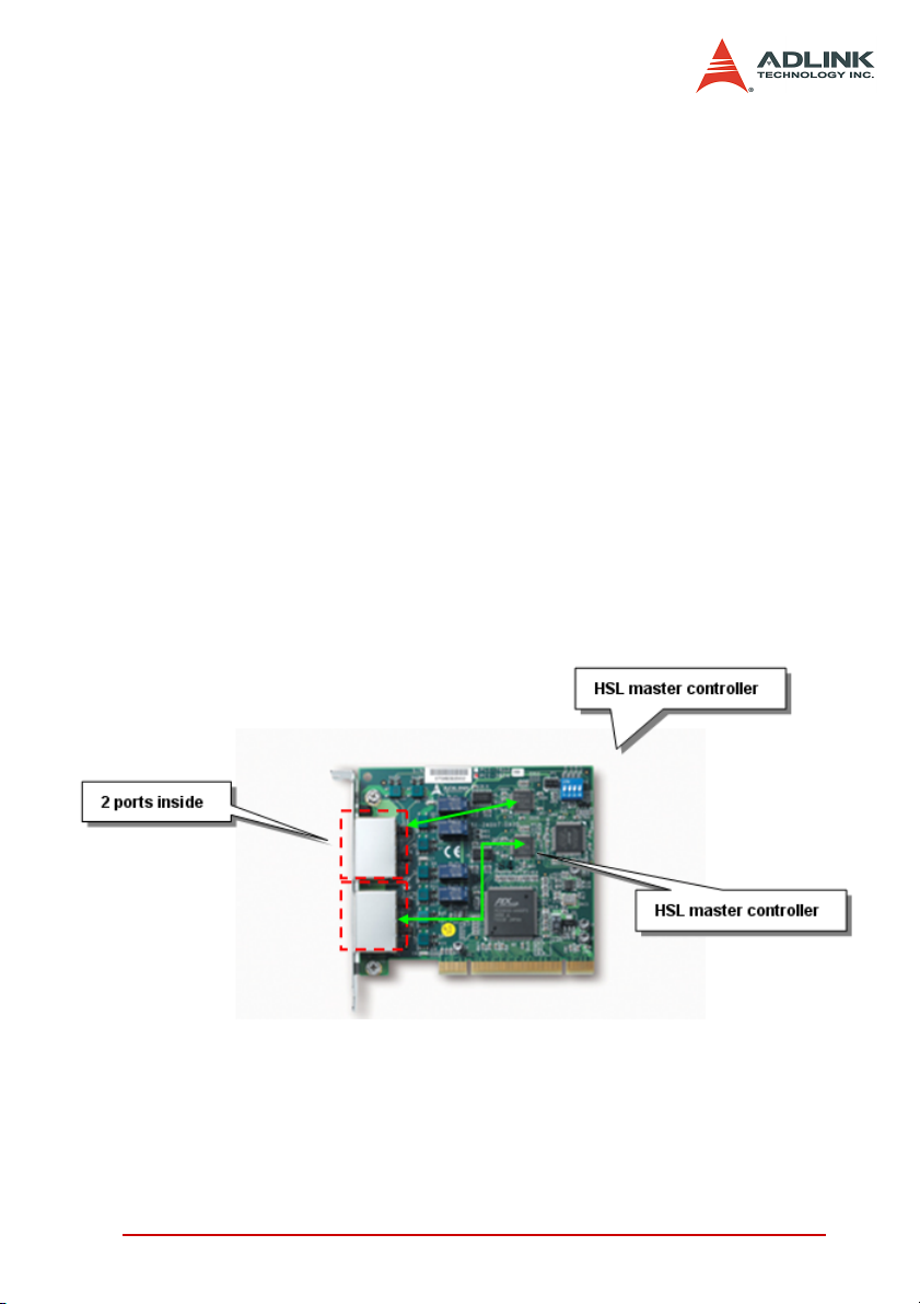
HSL master controller. One HSL ASIC plays the role of master
controller. For example, PCI-7853 has one on-board HSL ASIC; it
can connect a maximum of 63 slave indexes. For convenient connection, the HSL master has two ports. Using the same technology, the PCI-7854 can connect a maximum 126 slave indexes and
has four ports.
Transmission speed. The data speed is between master board
and slave modules. The unit is bit per second.
How to Use This Manual vii
Page 12

viii How to Use This Manual
Page 13

Page 14

1 Introducing HSL
1.1 The HSL System
The HSL is an innovative distributed I/O technology that enables
time-deterministic scanning of thousands of I/O points in milliseconds using master-slave architecture. The HSL master board
comes in PCI or PMC form factors. The PMC board is used in
embedded controllers. By using commercial Ethernet cable with
RJ-45 connector, you can easily set up the HSL slave modules as
close as possible to the sensor devices, reducing wiring effort.
Aside from the I/O modules, ADLINK provides the remote motion
control module with 4-axis pulse train type. The HSL network suits
a variety of machine-making applications as it integrates discrete I/
O, analog I/O, thermocouple module, and motion control. This
local network delivers rapid response time, time-deterministic
scanning and multiple-axis control. With PMC module, you may
also integrate the HSL network with embedded solution platforms.
The HSL system features:
X Distributed solution based on PC architecture or embedded
platform
X Convenient wiring for remote distributed I/O modules,
including discrete I/Os and analog I/Os
X Space-saving and discrete low-profile U-series form factor
X Hundreds of discrete I/O points
X Time-deterministic, fast scanning
X High-speed data acquisition
X Up to 120 axes of remote motion control with two HSL mas-
ter controller of master board
X Motion control features point table management and motion
script download to enhance execution efficiency
Introducing HSL 1
Page 15
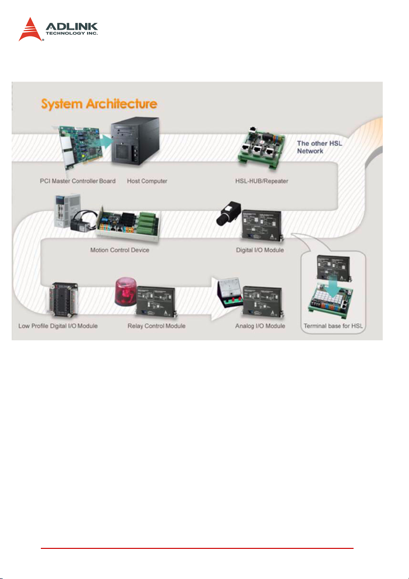
1.1.1 Product Overview
The illustration shows the basic HSL system topology.
Figure 1-1: HSL topology
1.1.2 Product Highlights
High-speed performance
With scanning speed as high as 1000 points per ms, it takes
only 1.895 ms for an HSL master to scan all the discrete I/O
points of slave modules under 6 Mbps. For example, a distributed control system with 63 slave I/O modules of HSLDI16DO16-DB-NN with 2016 discrete I/O points can be
scanned or updated within 1.895 ms.
2 Introducing HSL
Page 16
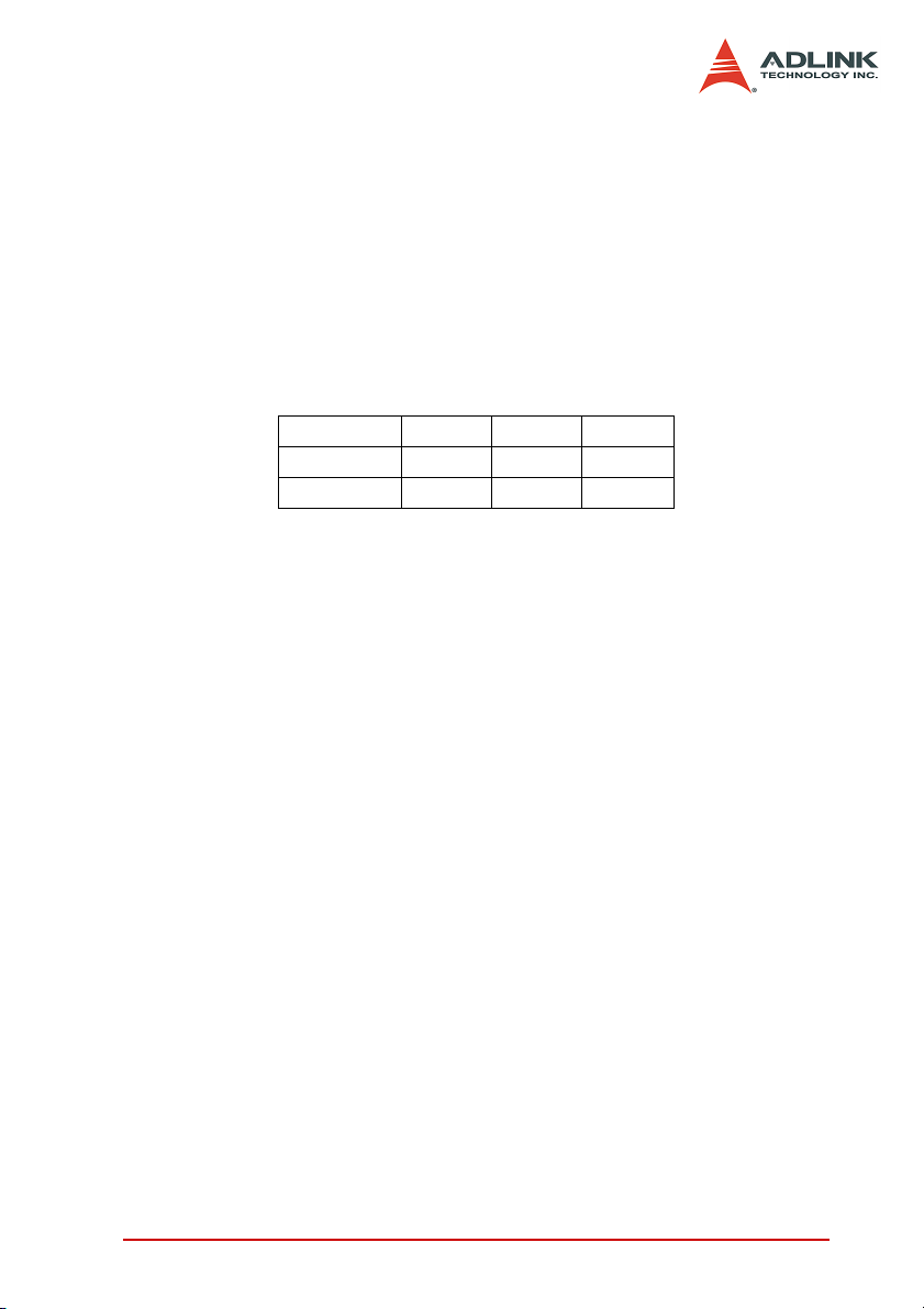
Time-deterministic scanning
The HSL master controller implements a deterministic time
period when scanning all slave I/O modules. The total scanning
cycle time is exactly proportional to the number of slave
indexes. At 6 Mbps, every 30.33 µs is added for another slave
index. For an HSL system with 30 discrete I/O slave modules
(where every discrete I/O module occupies one slave index),
the scanning time period is precisely 30 X 30.33 µs = 909.9 µs.
The scan time unit based on transmission rate is illustrated
below.
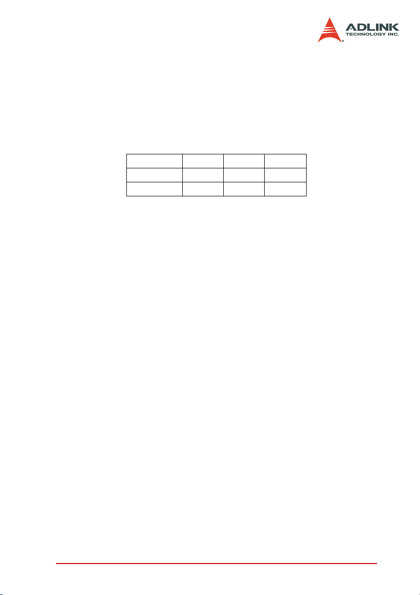
3 Mbps 6 Mbps 12 Mbps
Full Duplex 60.67 µs 30.33 µs 15.17 µs
Half Duplex 118 µs 59 µs 29.5 µs
Convenient wiring
The HSL master controller connects to all slave I/O modules
using Ethernet cables. This dramatically reduces the wiring
costs and effort. With Ethernet cables, hundreds or even thousands of I/O data can transmitted between the HSL master and
slave I/O modules. The HSL wiring is the easiest and most
cost-effective solution to date. For low profile series, you can
make the connection by direct wiring.
Multiple I/O points
The PCI-7853 offers one HSL master controller while the PCI7854 offers two HSL master controllers. For maximum installation, users can have eight PCI-7853 and PCI-7854 in one system. That means users can have 1512 slave indexes in HSL
network system. If choosing all connected modules as HSLDI16DO16-DB-NN, a total of 24,192 digital input and 24,192
digital output points are supported. For embedded solution,
users can choose the PMC-7852/G.
Easy I/O expansion
Expanding I/O points for centralized configuration requires
more I/O boards and available PCI or ISA slots. Problems
occur when system needs more I/O points while there are no
Introducing HSL 3
Page 17

available slot. In contrast with centralized configuration, the distributed I/O configuration eliminates this limitation of a centralized I/O configuration. With the HSL system, adding more I/O
points only requires one more slave I/O module and an Ethernet cable for communication link.
Self-diagnostic function
The HSL provides a self-diagnostic function that eliminates
communication failures. This function continuously monitors
the network status while a status register keeps the accumulated slave-no-response count for every individual slave I/O
module. Also, the HSL system features the CRC12 to eliminate
any communication error.
Modular design of slave I/O
ADLINK offers a variety of slave module types Including the
metal-cased M series, non-metal DB series, and U series for
compact systems. The M and DB series require a terminal
board for connection. Terminal boards act as carrier of slave I/
O module with wiring function. The Ethernet port and screw terminal on the terminal boards make it easier to replace I/O modules without turning and wiring off the system.
Remote motion control compatibility
ADLINK also offers remote motion control solution based on
the HSL network Including the HSL-4XMO-CG-N/P and HSL4XMO-CD-N/P that could connect up to four axes. The HSL4XMO-CG-N/P features a general-type interface for use with
stepper or linear motors, while the HSL-4XMO-CD-N/P has a
D-sub interface. By using a transfer cable, you can connect to
specific servo amplifier. You can easily make a distributed control application that includes discrete I/O, analog I/O, and
remote motion control.
Easy to program
Every HSL master card comes with 32 KB SRAM that carries
all the I/O status information of the HSL system. The ASIC on
the HSL master board communicates with all remote slave I/O
4 Introducing HSL
Page 18
modules at fixed scanning period and keeps the most updated
I/O status information on the SRAM. You may read and write
the data in the 32 KB SRAM on HSL master card through the
PCI or PMC bus. You can easily read/write the most updated I/
O information and never worry with the HSL protocol.
1.1.3 HSL Applications
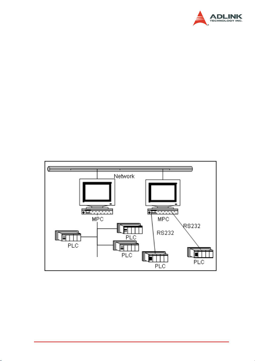
HSL as a Distributed PLC
The distributed PLC is an important system in the field of industry automation. Via communication modules, such as RS232,
RS485, PLC also performs distributed control. The traditional
architecture of distributed PLC application is shown in Figure
1.2. In this setup, the MPC (Monitoring PC) takes over as the
medium for data transmission from field to MIS.
RS-485
Figure 1-2: Traditional distributed PLC architecture
With the development of communication technology and popularity of networking, networking modules with Ethernet interface
became available. This improvement evolved as shown in the
architecture below. The medium character of the MPC was
replaced.
Introducing HSL 5
Page 19
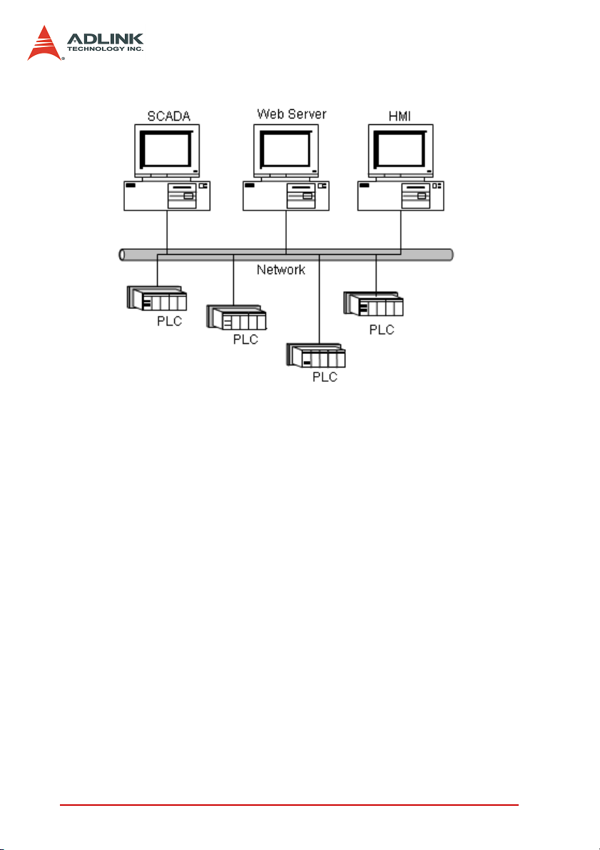
Figure 1-3: Networking PLC
PLCs that are capable of network communications are usually
very expansive. And since the PLC is not an open architecture,
only hardware vendors are capable of producing it.
6 Introducing HSL
Page 20
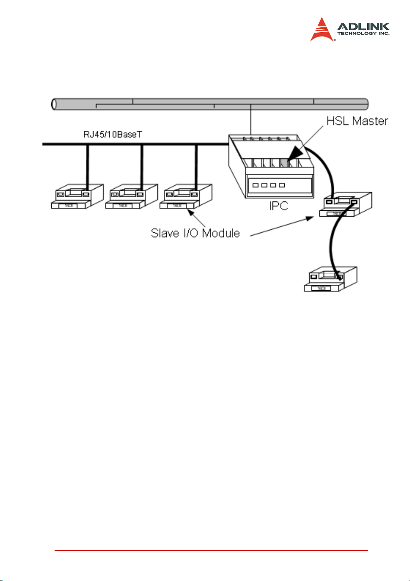
The HSL distributed control architecture is illustrated in Figure 1.4.
With HSL, there is no need for an extra PC for Ethernet communication. You may use only one IPC to control the entire system.
Figure 1-4: HSL as distributed PLC
Comparison between traditional PLC systems and HSL as distributed PLC
X The MPC is replaced by a PC with HSL Master
X The HSL slave I/O module is replaced by a remote side
PLC
X The RS485 or RS232 cable is replaced by simple Ethernet
cable
X The protocol handling is replaced by simple memory read/
write.
HSL as Remote Time-deterministic DAQ
The HSL system, with high-speed performance and deterministic time-deterministic scanning, is also applicable for remote
time-deterministic data acquisition.
Introducing HSL 7
Page 21
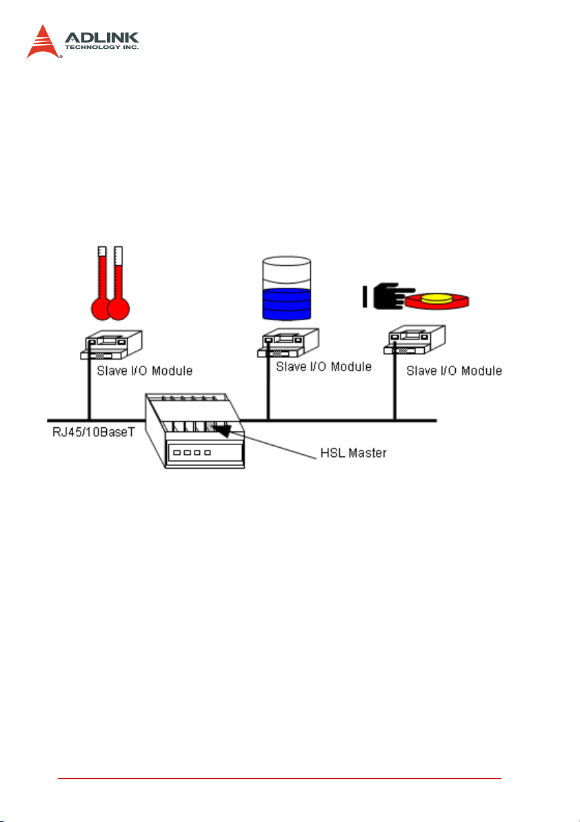
The time-deterministic characteristic of an HSL system is an
important factor when implementing a DAQ application. With
an HSL system, all I/O data are refreshed in time-deterministic.
The sampling rate (or scan rate) is linearly dependent on the
number of slave indexed occupied, ranging from 91 µs (less
than three slave indexes) to 1.911 ms (63 slave indexes) under
6 Mbps. These two features go with HSL’s remote capability to
make it suitable for remote DAQ applications, especially when
time-deterministic is of utmost concern.
Figure 1-5: Time-deterministic DAQ using HSL
8 Introducing HSL
Page 22
1.2 HSL System Specifications
Platform
X Hardware platform: Industrial PC with PCI Bus/Embedded
SBC with PMC connector
X Operating system platform: Windows® 98/2000/NT/XP or
Linux Redhat
Software support
X Windows XP/2k library
X Linux: Kernel 2.4.x
HSL Master Board
X PCI -7853 single HSL master controller board with two ports
X PCI -7854 dual-HSL master controller board with four ports
X PMC-7852/G dual-HSL master controller board with four
ports and PMC connector
Remote operation
One master controller has two ports. One port uses the RJ-45
phone jack as connector. One phone jack can drive a maximum 32 modules at maximum. One master controller can connect maximum 63 slave indexes.
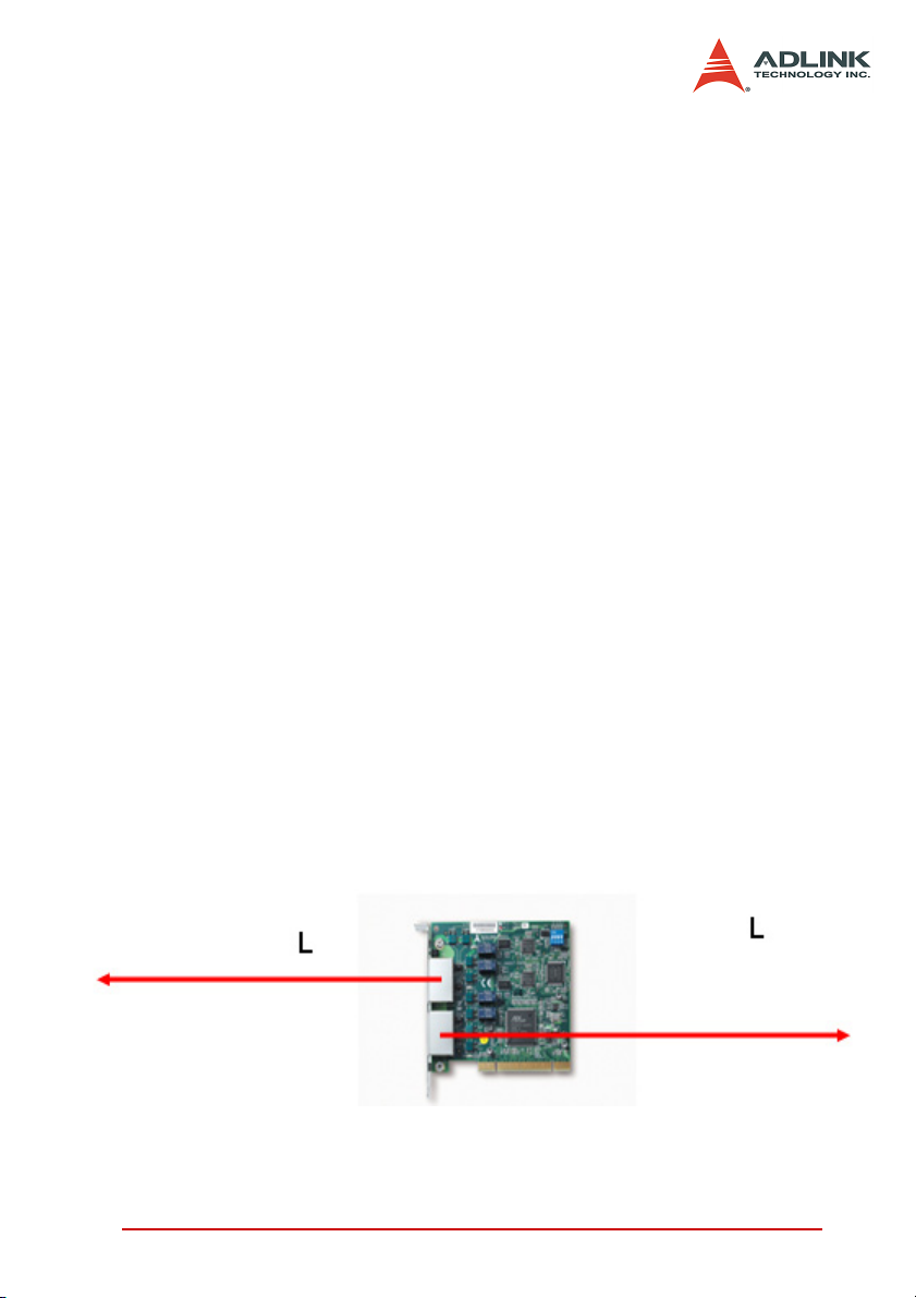
The maximum wiring distance for each RJ-45 connector (one
port) is 200 m @ 6 Mbps (serial wiring from master to last slave
module). The maximum length of port connection may be 400
m @ 6 Mbps since both sides are 200 m in length.
Introducing HSL 9
Page 23
Transmission Speed L (m)
3 Mbps 300
6 Mbps 200
12 Mbps 100
Table 1-1: Remote Operation
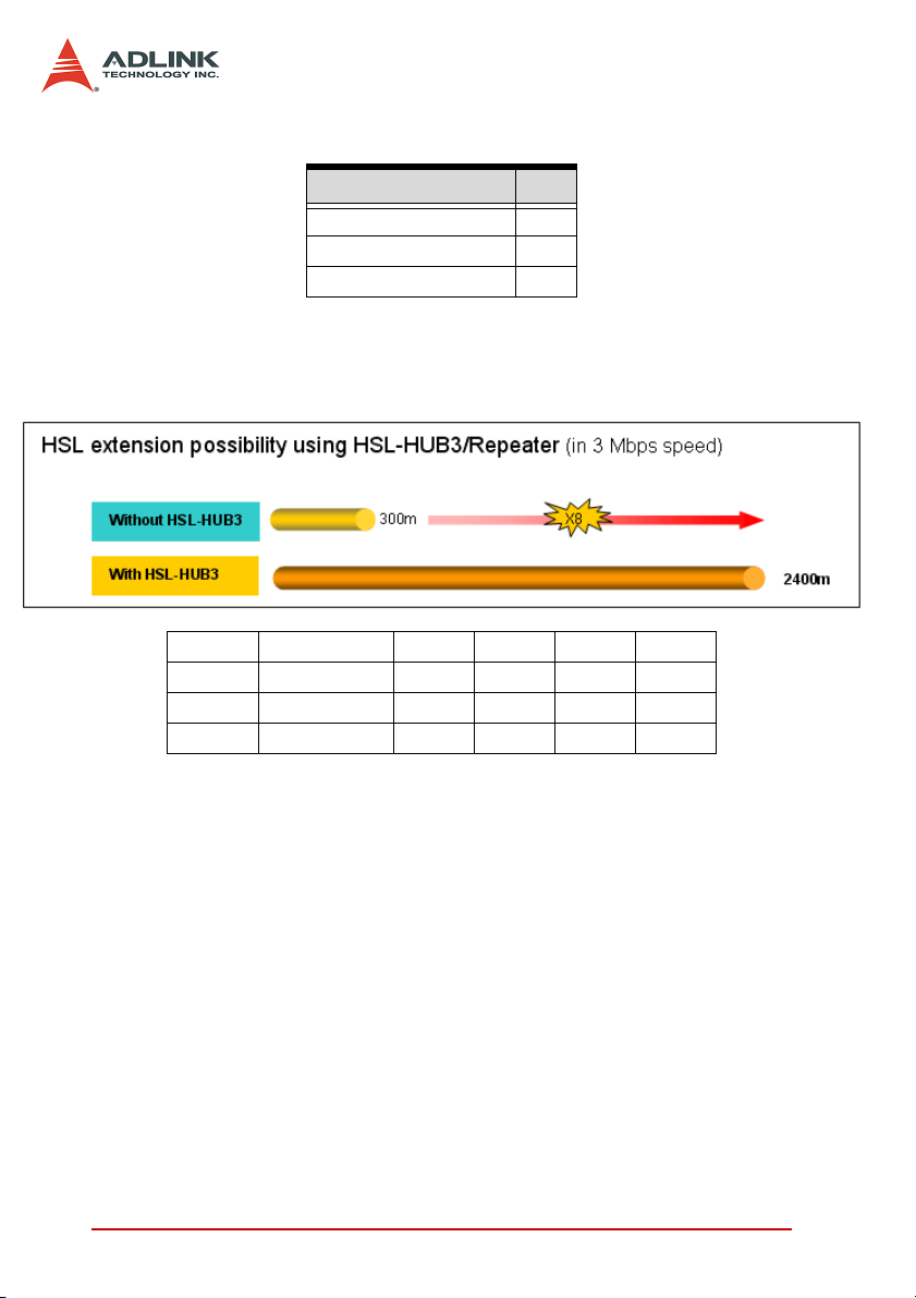
Supports maximum 2.4 km wiring via seven HSL-HUB/
Repeater modules
Without HUB HUBX1 HUBX2 HUBX5 HUBX7
12 Mbps 100 m 200 m 300 m 600 m 800 m
6 Mbps 200 m 400 m 600 m 1200 m 1600 m
3 Mbps 300 m 600 m 900 m 1800 m 2400 m
Wiring
X Connector: RJ-45 (on master controller and some of slave
modules)
X Cable: Cat-5 100 Base/TX Ethernet cable with shielding
10 Introducing HSL
Page 24
Communications
X Multi-drop full-duplex RS-422 with transformer isolation
scheme
X Transmission speed: 3/6/12 Mbps (6 Mbps is factory default
setting).
X I/O refresh rate: scan time unit × numbers of slave indexes
(minimum is 3; maximum is 63)
3 Mbps 6 Mbps 12 Mbps
Full Duplex 60.67 µs 30.33 µs 15.17 µs
Half Duplex 118 µs 59 µs 29.5 µs
X Communication model: single master to multi-slave
X Communication method: command/response type hand-
shaking
X CRC12 and dedicated protocol for eliminating communica-
tion errors
Introducing HSL 11
Page 25
1.3 HSL Series Products
HSL Master controller boards
See HSL Master Board on the previous section.
At least one master controller card is needed for an HSL system. With PCI-7854 or PMC-7852/G, two master controllers are
available. A maximum of 12 cards are supported for a single
computer system.
Slave I/O modules
A variety of HSL slave I/O modules are available.
Series Model
HSL-DI32-DB-N/P 32 (1,3, 5, …,61) 2
DB
M
U
HSL-DO32-DB-N/P 32 (1,3, 5, …,61) 2
HSL-DI16DO16-DB-N/P 16 16 1-63 1
HSL-DI32-M-N/P 32 (1,3,…,61) 2
HSL-DO32-M-N/P 32 (1,3,…,61) 2
HSL-DI16DO16-M-NN/NP/PN//PP 16 16 1-63 1
HSL-R8DI16-M-N/P 16 8 relay 1-63 1
HSL-AI16AO2-M-VV 16 2 1-61 2
HSL-AI16AO2-M-AV 16 2 1-61 2
HSL-DI16DO16-US/UJ 16 16 1-63 1
HSL-DI16-UL 16 1-63 1
HSL-AO4 4 1-62 2
Discrete
Input
Discrete
Output
Analog
Input
Analog
Output
Start Index
Setting Range
Table 1-2: Slave I/O modules
Note: Start Index Setting Range means range of the start index
address of DIP switch setting. Full duplex and half duplex
mode have different ranges.
The following remote motion control modules are also supported:
Series Model Axes Interface
HSL-4XMO-CG-N/P 4 General series
Motion
HSL-4XMO-CD-N/P 4 D-sub
Table 1-3: Remote Motion modules
Start In dex
Setting Range
1~60 for Half Duplex
1~57 for Full Duplex
Slave Index
Occupation
4
Slave Index
Occupation
12 Introducing HSL
Page 26
Note: Start Index Setting Range means range of the start index
address of DIP switch setting. Full duplex and half duplex
mode have different ranges.
Terminal Base
A variety of HSL terminal base are also available.
Model Numbers Module Type Support Module Number Support
HSL-TB64-DIN All the HSL DB series 2
HSL-TB32-U-DIN All the HSL DB series 1
HSL-TB32-M-DIN All the HSL M series 1
HSL-TB32-MD All the HSL M series 1
Table 1-4: Terminal Base
Introducing HSL 13
Page 27
1.4 Technical Information
1.4.1 HSL Technology Introduction
Inside an HSL system, a single master controller communicates
with multi-slave through a command-response. The master controller sends commands to slave I/O modules for setting output
values and requesting input information. Every slave module
responds after receiving commands with address ID. The
responses may either be to set output according to the received
values or to reply requested input information to the master controller.
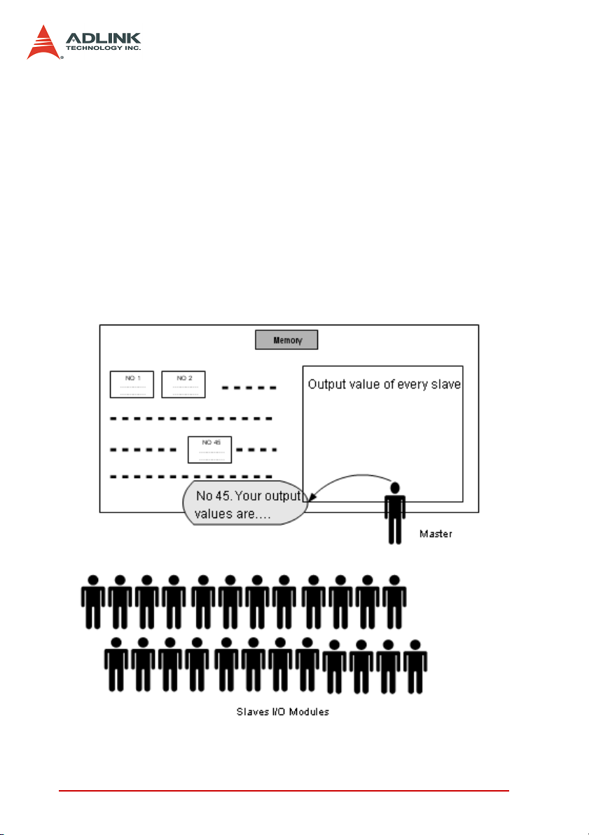
The illustration below shows the HSL working theory as regards
the setting of output values.
Figure 1-6: HSL technology brief -1
14 Introducing HSL
Page 28
The teacher (master) sends message “ID.#, your output values
are XXX” to all students (slave I/O modules). Every student (with
ID.#) then sets its output channels according to the values heard.
The values that the teacher announced to the students are written
on the blackboard (RAM on master cards), and can be easily modified.
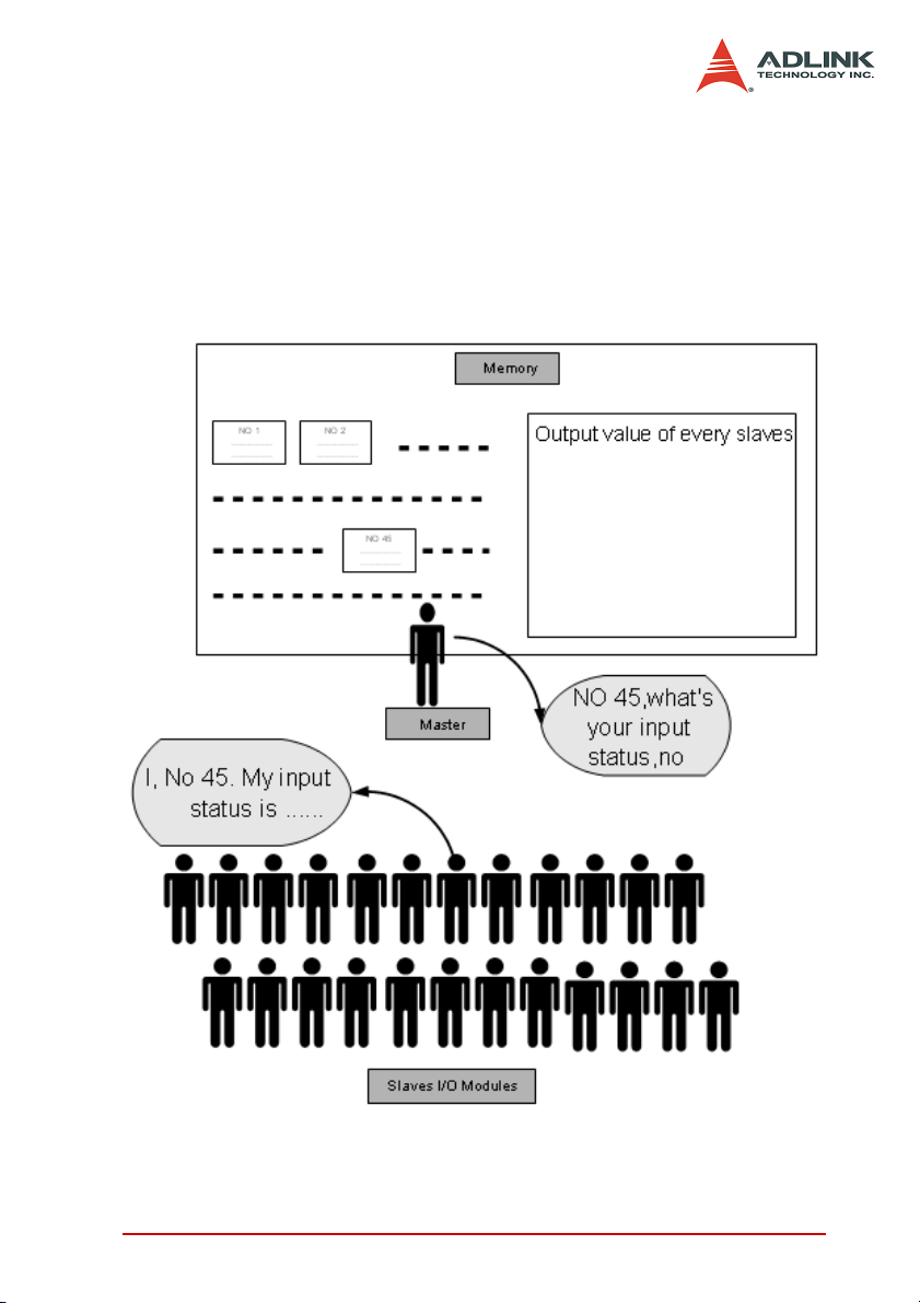
The following illustration shows the working theory for gathering
input information.
Figure 1-7: HSL technology brief-2
Introducing HSL 15
Page 29

The teacher (master) sends the message “ID.#, what is your latest
input status” to all students (slave I/O modules). Every student
(with ID.#) then gives his answer. The teacher writes the answers
on the blackboard (RAM on master cards). When someone (user’s
AP) wants to know the students’ answers, he refers to the blackboard. All input information are saved in the memory.
These two procedures take turn and repeat on every slave module. After each cycle, each slave module sets its newest output
status and the master gathers all these information from the memory. We simulate the polling communication cycle through a
teacher-student conversation:
Teacher: Student No. 1, your output vales are ##, what’s your latest input status?
Student No. 1: My input status is ##
Teacher writes the answer on the blackboard.
Teacher: Student No. 2, your output vales are ##, what’s your latest input status?
Student No. 2: My input status is ##
Teacher writes the answer on the blackboard.
Until…
Teacher: Student No. 63, your output vales are ##, what’s your latest input status?
Student No. 63: My input status is ##
Teacher writes the answer on the blackboard.
The polling cycle is now complete. The process repeats from Student No. 1.)
16 Introducing HSL
Page 30

Figure 1-8: HSL I/O polling cycle
Introducing HSL 17
Page 31

The HSL master-slave communication architecture is illustrated
below:
Figure 1-9: Master-slave communication architecture
18 Introducing HSL
Page 32

1.4.2 HSL Terminology
In addition to the input/output polling mechanism shown above,
here are some HSL-related syntax for your reference.
HSL Master. Master is defined as the teacher in Figure 1.9 and
1.10. The master takes charge of giving commands, including output value announcements and latest input status requests.
Slave I/O Module. Slave I/O modules are defined are the students
in Figure 1.9 and 1.10. Slave I/O modules are passive components in an HSL system. They receive commands from the
master, then respond by telling their newest input status or by setting output values. The slave I/O modules may take one or two
address indexes depending on the I/O module type.
Polling Cycle. When communicating with slave I/O modules, the
master takes turn setting the output for and gathering input from
every slave module. When all slave modules are updated, a polling cycle is completed. The polling cycle infinitely repeats when
the master is working properly.
I/O Refreshing Rate. The time needed to complete an I/O updating cycle. This may also be the longest time needed for any digital
I/O channel to obtain its latest status. The refreshing rate is
decided linearly by the total number of slaves used in an HSL system, therefore no interference occurs between any two HSL systems or PC/IPC at the same time.
Transmission Speed. May refer to the speed of digital signal
transfer or I/O refreshing rate. When referring to the speed of digital signal transfer inside the cable, the transmission speed is
known as data rate. The unit of transmission speed is bits per second (bps). The unit of I/O refreshing rate speed is expressed in
mini-second (ms).
Introducing HSL 19
Page 33

1.4.3 System Configurations
To develop an HSL application, you must know how to configure
the HSL cards and slave I/O modules. The following sections
describe the configuration concepts for an HSL system. For
detailed information, refer to individual chapters.
Master Card Index (card_ID). You can install one or more HSL
master boards in an IPC system. The PCI BIOS assigns the card
index for each HSL master board. You need to specify the card
index for programming purposes. The card index is starts from 0.
Figure 1-10: Multiple master cards in one IPC
Refer to Chapter 2: HSL Master Controller for more information.
HSL Connect Index (connect_index). The PCI-7853 provides
only one HSL master controller (connect_index=0), while PCI7854 or PMC-7852/G provides two HSL master controllers
(connect_index=0 or 1). Connect index distinguishes the master
controllers.
Ports. Port refers to the RJ-45 connector on the HSL master
board. A connector is a loop of wiring that starts from the master
card and connects to up to 32 slave I/O modules. There are two
ports in one HSL master controller, both carrying the same signals
sent from the master.
20 Introducing HSL
Page 34

Slave Index. A complete HSL system is composed of one master
and 1 to 63 slave indexes. The following diagram illustrates an
HSL system.
Figure 1-11: HSL system layout example-serial wiring
Every master circuit can support up to 32 slaves. However, since
the slave address is assigned by a 6-bit DIP-switch on the I/O
module’s termination board with the value ‘0’ reserved, the maximum number of slaves is 63, not 64. The slave I/O modules in an
HSL system must have different slave index. Though the slave
index may not necessarily continue from 1, continuous addressing
is more efficient. When an HSL system has only two slave modules addressed 1 and 63, the I/O refreshing rate is the same with
an HSL system with 63 slave modules addressed from 1 to 63.
Refer to Chapter 3: HSL Slave I/O Module for procedures on how
to set the addresses of slave I/O modules.
Introducing HSL 21
Page 35

1.4.4 Wiring
The HSL network follows a modified RS-422 electrical specification.
Wiring
The wire cables of an HSL system are carefully selected for
installation convenience and standardization without sacrificing
communication quality. A 100BaseTX cable with RJ-45 connectors is used on HSL systems.
Full-duplex RS-422 with multi-drop
The typical RS-422 is not a networking specification. However,
HSL modified the specification to suit network applications. The
TXD of the master is connected to the RXD of every slave I/O
modules, while all TXD of slaves are connected to the RXD of
the master. Only the master uses TXD (of master) to RXD (of
slave) channel. Through design, only one slave at a time sends
message with TXD (of slave) to RXD (of master) channel. This
kind of networking solution is called RS-422 with multi-drop.
Ports
An HSL master supports a 2-port segment. Inside the ports, the
TXD (of master) to RXD (of slave) channels are of the same
signal sent by master. In contrast, the TXD (of slave) to RXD
(of master) channels are isolated from each circuit and signals
inside do not pass through the master from one circuit to
another.
22 Introducing HSL
Page 36

The diagram below illustrates RS-422 with multi-drop:
Figure 1-12: HSL wiring – RS-422 with multi-drop
X There are two RJ-45 notches in each master. Each notch
supports one port of wiring.
X Only four lines of the RJ-45 cable are used: two for trans-
mission and two for reception.
X All slave modules are connected in parallel.
X The isolation between connection cable and individual slave
I/O modules protects the signals from interference by other
slaves.
Introducing HSL 23
Page 37

1.4.5 Networking Topology
Base on the RS-422/RS-485 architecture, a variety of topologies
are available for an HSL circuit, including serial, multi-drop, star,
etc. The following sections illustrate some applicable network
topologies for your reference.
Serial wiring
All slave I/O modules are connected using a twin-head
100BaseTX cables.
Figure 1-13: HSL networking topology – Serial
Since two notches of any slave I/O module’s termination board
are short circuit, this type of wiring provides the most convenient and intuitive way to form a HSL network. The longest wiring length is 200 m with under 6 Mbps.
24 Introducing HSL
Page 38

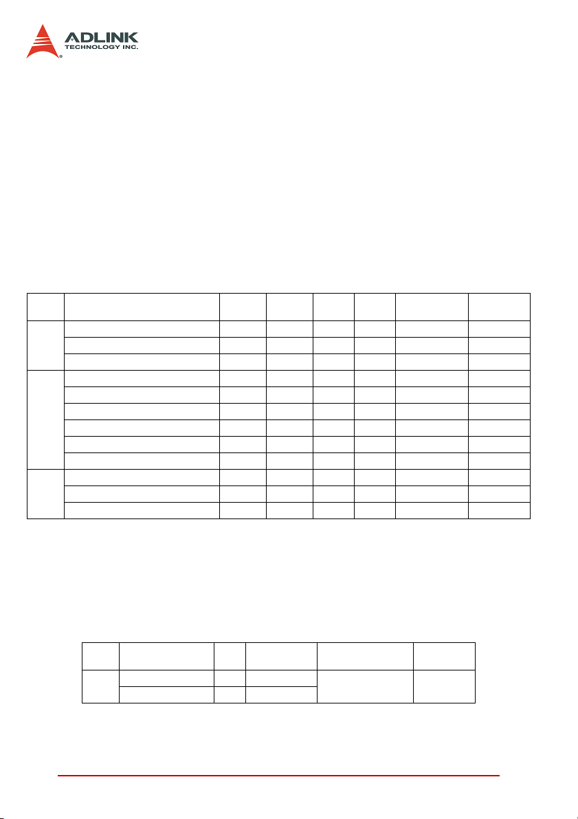
1.4.6 I/O refreshing rate of an HSL system
The scan time unit for one slave index is set in 3/6/12 Mbps transmission rate. Once the maximum slave address is set, the polling
cycle time of the HSL system is using the following formula:
Polling cycle time = maximum-address-of-slave * scan time unit
Maximum
address
10 606.67µs 303.33 µs 151.67 µs
20 1.213 ms 606.67 µs 303.33 µs
30 1.820 ms 910.00 µs 455.00 µs
40 2.427 ms 1.213 ms 606.67 µs
50 3.033 ms 1.516 ms 758.33 µs
60 3.640 ms 1.820 ms 910.00 µs
63 3.822 ms 1.911 ms 955.50 µs
Cycle Time
under 3 Mbps
5 303.33 µs 151.67 µs 75.83 µs
Cycle Time
under 6 Mbps
Cycle Time
under 12 Mbps
Table 1-5: Polling cycle time of HSL (Full Duplex Mode)
Note: Regardless of the transmission rate you select, the minimum
polling cycle time is 3×scan time unit, even when the maximum address is less than 3. Refer to Appendix A.
Introducing HSL 25
Page 39

1.4.7 Communication error handling
The HSL communication protocol is designed to eliminate any
error, there may be some chances of communication errors such
as light striking, sudden off-line, etc. In an HSL system, the master
holds an accumulated slave-no-response count for every individual slave I/O module. The count value is updated for each slave
module in every polling cycle.
X If communication with certain slave I/O module is success-
ful, the no-response count value for this slave is set to 0.
X If the communication failed, the no-response count value
increases by 1.
X When the count is larger than or equal to 3, a binary flag
indexing communication error is set to True.
X The maximum value of no-response count is 7. The value is
retained even if the error continues to occur.
The no-response count value and the communication error flag
status may be obtained by software function call. These error handling data are also returned every time the user wants to set or get
the I/O values.
In addition, the HSL, through a software communication error-handling driver, supports a self-diagnosis function that detects off-line
or out-of-communication slave modules. In a programmed period
of time (default 20 ms), the master sends an IRQ to trigger the
driver to check the slave’s no-response count value. If the count
value is 7, the driver informs the system that the slave module is
off-line.
26 Introducing HSL
Page 40

1.5 Software Support
Window® 2000/XP DLL
The provided Windows® 2K/XP DLL (Dynamic Link Library) is
a programming interface for systems using Microsoft® Windows®. The driver works with any Windows® programming
language that integrates DLL such as Visual C/C++ (6.0 or
above), Borland C++(5.0 or above), or Visual Basic (6.0 or
above).
Linux Driver
The HSL Linux driver includes device drivers and shared
library for Linux-based systems. The developing environment
can be GNU C/C++ or any programming language that allows
linking to a shared library. The Linux driver is included in the
ADLINK All-in-one CD.
Introducing HSL 27
Page 41

28 Introducing HSL
Page 42

2 HSL Master Controller
The HSL master is the key component in charge of communicating with slave I/O modules. The master sets output values to and
gathers input information from slaves.
ADLINK presents four types of HSL master cards: PCI-7853, PCI7854 and PMC-7852, and PMC-7852/G. The main difference
between these cards is the number of supported HSL master.
X PCI-7853: Single HSL Master Controller Interface Card
X PCI-7854: Dual-HSL Master Controller Interface Card
X PMC-7852/G: Dual-HSL Master Controller Interface Card
with PMC connector
2.1 Board Overview
Figure 2-1: PCI-7854 front view
HSL Master Controller 29
Page 43

2.2 Specifications
PCI Bus
X PCI local bus specification Rev. 2.1-compliant
Master Controller
X HSL ASIC master controller
X 48 MHz external clock
Interface
X RS-422/RS-485 with transformer isolation
X Half/Full duplex communication
X 3/6/12 Mbps transmission rate through a S/W function set-
ting (default is 6 Mbps)
X Two ports for each master controller
Connector
X RJ-45 connector x 2 (CN1 for PCI-7853)
X RJ-45 connector x 4 (CN1, CN2 for PCI-7854; H1A, H1B,
H2A, H2B for PMC-7852/G)
Interrupt
X 16-bit programmable timer with 5µs resolution
LED Indicator
X Link status
Dimension
X PCI-7853/7854: 122 (L) × 107 (W) mm
X PMC-7852/G: 74 (W) × 149 (W) mm
Operating Temperature: 0°C to 70°C
Storage Temperature: -20°C to 80°C
Power Consumption: +5V @ 500 mA typical
30 HSL Master Controller
Page 44

2.2.1 PCI-7853/7854 Layout
S1
Figure 2-2: PCI-7853/7854 Layout
CN1: RJ-45 connector with first HSL master controller
CN2: RJ-45 connector with second HSL master controller (PCI-
S1: Card ID switch selection
HSL Master Controller 31
7854 only)
Page 45
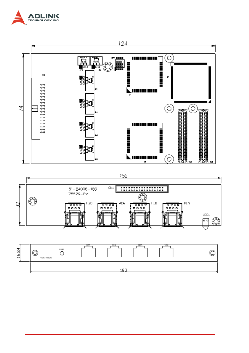
2.2.2 PMC-7852/G Layout
Figure 2-3: PMC-7852/G Layout
X H1A, H1B: RJ-45 connector with first HSL master controller
X H2A, H2B: RJ-45 connector with second HSL master con-
troller (PMC-7852 only)
32 HSL Master Controller
Page 46

X JP1, 2, 3, 6: Full/Half duplex mode with first master control-
ler (Default: Full duplex mode)
X JP4, 5: Full/Half duplex mode with second master controller
(Default: Full duplex mode)
X SW1: Transmission speed option. (Default: 6 Mbps)
HSL Master Controller 33
Page 47
2.3 Configuration
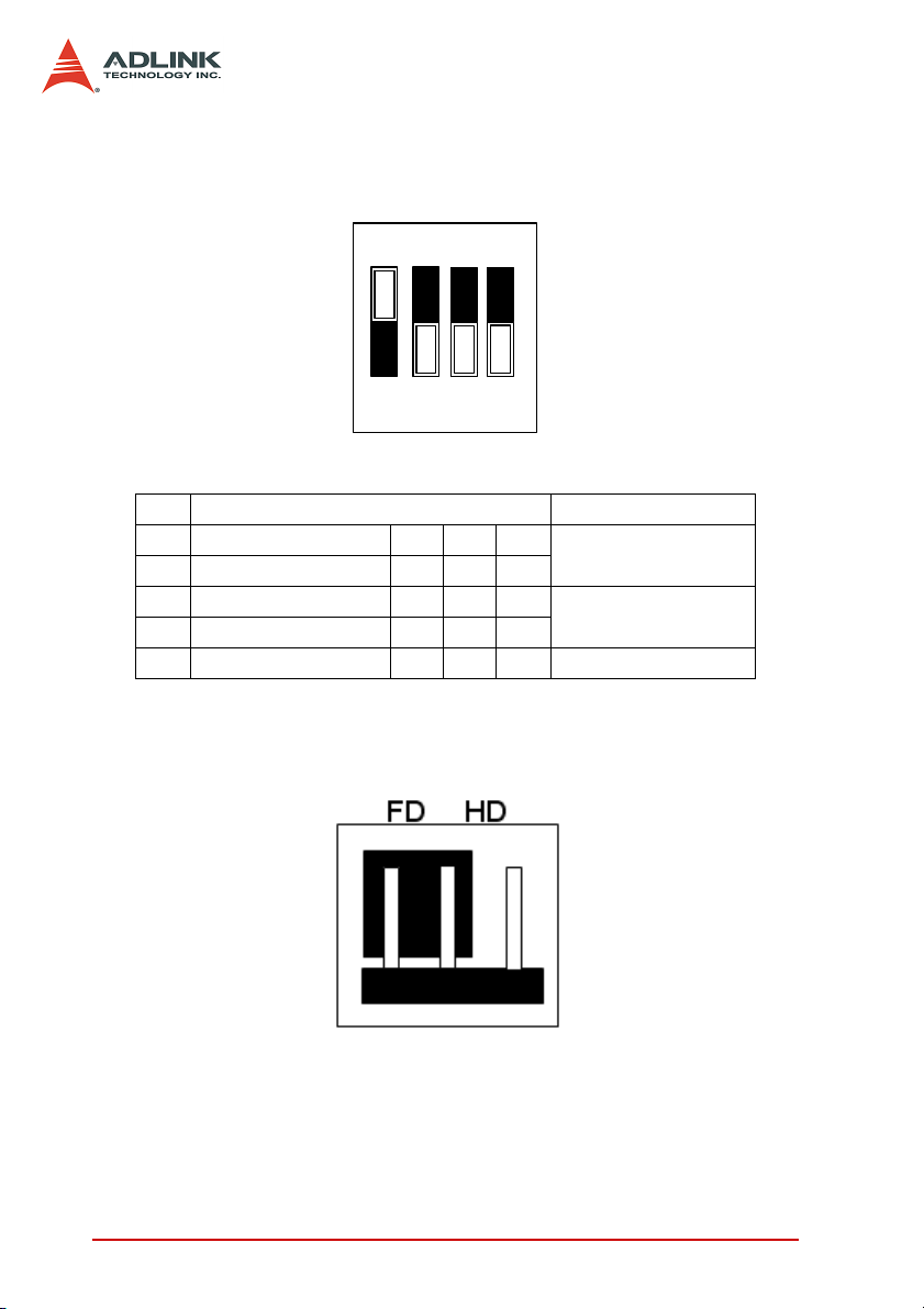
2.3.1 SW1 (PMC-7852/G only)
Figure 2-4: SW1 – Transmission Rate Setting
No. Set transmission rate
1OFFONOFFON
2OFFOFFONON
3OFFONOFFON
4OFFOFFONON
Rate 12M 6M 3M EXC
Default: 6 Mbps.
2.3.2 JP 1, 2, 3, 6 / JP 4, 5 (PMC-7852/G only)
1st Master Controller
2nd Master Controller
Figure 2-5: Top View of PMC-7852/G, for JP 1, 2, 3, 4, 5, 6 jumper settings.
34 HSL Master Controller
Page 48

2.4 PIN Assignment (female)
HSL Master Controller 35
Page 49

2.5 Software Architecture Description
The PCI-7853/PCI-7854/PMC-7852/G comes with one or two HSL
master ASICs that control the HSL communication. The purpose
of communicating with HSL I/O modules is to gather input data
from or set output value to them. To achieve this purpose, each
HSL master controller manages a 2Kbyte SRAM on PCI-7853/
PCI-7854 boards for data storage.
For every polling cycle, the master refreshes all input data from
the I/O modules and sets the latest output data to the I/O modules.
The SRAM keeps these data for the software drivers to read/write
I/O information.
2.5.1 Functional Block Diagram
Figure 2-6: Functional Block diagram of HSL master
The diagram above shows how the HSL communicates with the
user’s AP. The SRAM acts with a buffer-like characteristic.
36 HSL Master Controller
Page 50

2.6 Installation
2.6.1 Hardware Installation
The PCI-7853/PCI-7854 is a plug and play device, with the system
BIOS automatically assigning the interrupt channel and memory
mapping address. You only need to adjust the SW1 to the desired
transmission speed. For PMC-7852/G, refer to GEME user manual
for details.
2.6.2 Software Installation
Refer to chapter 4.1.
HSL Master Controller 37
Page 51

38 HSL Master Controller
Page 52

3 HSL Slave Module
The HSL is a master-slave network system that features an innovative distributed architecture that modularizes the communication, I/O functions and signal termination. ADLINK provides a
complete line of slave I/O modules and terminal bases including
discrete I/O, analog I/O, and motion control to meet your application requirements. For motion control modules, refer to the HSL4XMO user’s manual.
Slave I/O Module. There are three groups of slave I/O modules
with varied dimensions. The slave I/O modules provide the terminal base with different levels of I/O capability. To identify each
slave I/O module in an HSL network, an electronic data sheet is
embedded in the module, and each module is identified by an
address ID configurable via the 6-bit DIP switch. Depending on the
I/O support, each slave I/O module may be assigned one or two
address IDs. Since the highest ID number in an HSL master is 63
(6-bit and ‘0’ reserved for master), up to 63 slave I/O modules are
supported in one HSL master.
Terminal Base. Offers an easy wiring media. Both power and signal wiring go from the terminal base to the slave I/O modules.
Also, master links to all slave I/O modules via the terminal base
using an RJ-45 cable. The TB makes the slave I/O modules hotswappable without interfering other modules in the same HSL network.
HUB/Repeater. Provides sub-system support for various network
topologies.
Wiring Cable. The cables connecting the HSL master and slave I/
O modules are standard 100 Base/TX with RJ-45 connectors.
These are exactly the same with commercial Ethernet cables.
HSL Slave Module 39
Page 53

3.1 Slave I/O Module
3.1.1 Discrete I/O Module
ADLINK provides three I/O module series: DB, M and L.
X DB: Daughterboard form factor
X M: Daughterboard form factor with aluminum cover
X U: U-series
Series Model
HSL-DI32-DB-N/P 32
DB
M
U
HSL-DO32-DB-N/P 32
HSL-DI16DO16-DB-N/P 16 16 1
HSL-DI32-M-N/P 32
HSL-DO32-M-N/P 32
HSL-DI16DO16-M-NN/NP/PN//PP 16 16 1
HSL-R8DI16-M-N/P 16 8 1
HSL-DI16DO16-US/UJ-NN/NP/PN/PP 16 16 1
HSL-DI16-UL 16 1
Discrete
Input
Discrete
Output
Relay
Output
Slave Index
Occupation
2 (Consecutive
from odd number)
2 (Consecutive
from odd number)
2 (Consecutive
from odd number)
2 (Consecutive
from odd number)
Below is the selection guide.
HSL - DIxDOx - x - XY
Discrete I/O Type:
DI16DO16
discrete outputs
DI32
DO32
R8DI16
inputs
: 16 discrete inputs and 16
: 32 discrete inputs
: 32 discrete outputs
: 8 relay outputs and 16 discrete
Series:
: Daughter board
DB
form factor
: Daughter board
M
with aluminum cover
: U-Series
U
Signal Type:
X
: Input Signal
PN sink-
Type: N
ing and P
sourcing support
: Output Signal
Y
PN sink-
Type: N
ing and P
sourcing support
NP
NP
40 HSL Slave Module
Page 54

3.1.2 Analog I/O Module
ADLINK provides M series analog I/O module.
Series Model
HSL-AI16AO2-M-VV 16 2 2 (Leap number)
M
HSL-AI16AO2-M-AV 16 2 2 (Leap number)
Analog
Input
Analog
Output
Slave Index
Occupation
UHSL-AO4 4 2
Below is the selection guide.
HSL - AIxAOx - x - XY
Signal Type:
: Input signal
X
Discrete I/O Type:
AI16AO16
log outputs
: 16 analog inputs and 2 ana-
Series:
M: Daughter board
with aluminum cover
type, V means
voltage and A
means current.
: Output signal
Y
type, V means
voltage.
3.1.3 Motion Control
ADLINK provides the HSL-4XMO-CG-N/P and HSL-4XMO-CD-N/
P remote motion control cards. Below is the selection guide.
HSL - 4XMO - Cx - X
Series:
: The connection
Controllable Axes:
: 4-axis pulse train type motion
4XMO
control
CG
interface is general
type.
: The connection
CD
interface is D-sub 25.
The HSL-4XMO-CG-N/P is suitable for applications using stepper
and linear motors. For HSL-4XMO-CD-N/P, ADLINK provides the
accessories and transfer cable for direct connection to a servo
amplifier. For details, refer to the HSL-4XMO user’s manual.
Signal Type:
: Output Signal
X
PN sink-
Typ e: N
ing and P
sourcing support
NP
HSL Slave Module 41
Page 55

3.1.4 General Specifications
Discrete I/O Module
2500 V
4.7 k
Ω
For NPN
For PNP
For NPN
For PNP
For NPN
For PNP
ON to OFF: 68 µs
OFF to ON: 1.1 µs
SPST, normally open, non-latching
30 VDC/2 A; 250 VAC/2 A
20 times/minute at rated load
ON to OFF: 3 µs (max)
OFF to ON: 6 µs (max)
Discrete Input
Discrete Output
Relay
Photo couple isolation
Input impedance
Input Voltage +24 V *
Input Current
Operation Voltage
(@ 24 V
Response Time ON: 8.8 µs(Typical) ; OFF: 42 µs(Typical)
Switch capacity
Response Time
Power Supply)
DC
Relay Type
Rating
Switching Frequency
Response Time
(1): NPN sinking type sensor input module
(2): PNP sourcing type sensor input modules
(3): NPN sinking type sensor output module
(4): PNP sourcing type sensor output modules
(5): U-series all channels: -90 mA at 24
RMS
(1)
-10 mA
(2)
+10 mA
ON: 11.4 VDC (max)
(1)
OFF: 14.3 V
ON: 12.6 VDC (min)
(2)
OFF: 9.8 V
All channels
(3)
24V
DC
(4)
All channels: +50mA/ch at 24V
V
DC
(min)
DC
(max)
DC
(5)
: -50mA/ch at
DC
42 HSL Slave Module
Page 56

*Note: The HSL-DI16-UL supports 5 V, 12 V, and 24 V, selected
by a jumper for each channel:
X JDI0 - JDI15 (input voltage setting)
4.7 kΩ (@24 V
DI_COM @ 24 V
DI_COM @ 12 V
DI_COM @ 5 V
Discrete Input
Input impedance
Operation Voltage
Analog I/O Module
A/D Resolution 16-bit (14-bit guaranteed)
Analog Input
Input Range
A/D Conversion 10 µs
Signal Type 16-CH single-ended; 8-CH differential
Analog Output
D/A Resolution 16-bit
DA Settling Time 10 µs
Motion Control
Refer to the HSL-4XMO user’s manual.
, 2.74 k (@12 VDC), 1.1 k (@5 VDC)
DC
DC
DC
DC
ON: 14.0 VDC (max)
OFF: 18.0 V
ON: 6.0 VDC (min)
OFF: 8.0 V
ON: 1.0 VDC (min)
OFF: 3.0 V
DC
DC
DC
(min)
(max)
(max)
For VV type: ±10, ±5, ±2.5, ±1.25 V
For AV type: 20 mA, 10 mA, 5 mA
HSL Slave Module 43
Page 57

3.1.5 DIP Switch Setting:
Notes
(1) The address (or slave index) 0 is reserved.
(2) The HSL-DI32-M, HSL-DO32-M, HSL-DI32-DB, and HSL-
DO32-DB require two consecutive addresses starting from
an odd number. For example, if the DIP switch is set to 3, it
occupies slave index 3 and 4.
(3) The HSL-AI16AO2-M-VV/AV requires two leap addresses at
full duplex mode. For example, if the DIP switch is set to 2,
the module occupies addresses 2 and 4.
(4) The HSL-4XMO-CG-N/P and HSL-4XMO-CD-N/P require
four leap addresses at full duplex mode. For example, if the
DIP switch is set to 2, these modules occupy 2, 4, 6, and 8.
At half duplex mode, it requires 4 consecutive addresses.
44 HSL Slave Module
Page 58

3.1.6 Wiring Diagram
-N NPN Sinking type sensor Input
LED
v+
Circuit
IN
G
-N Dry Contact Input
v+
IN
G
-P PNP Sourcing type sensor Input
v+
Circuit
IN
G
Internal
Circuits
LED
Internal
Circuits
LED
Internal
Circuits
HSL Slave Module 45
Page 59
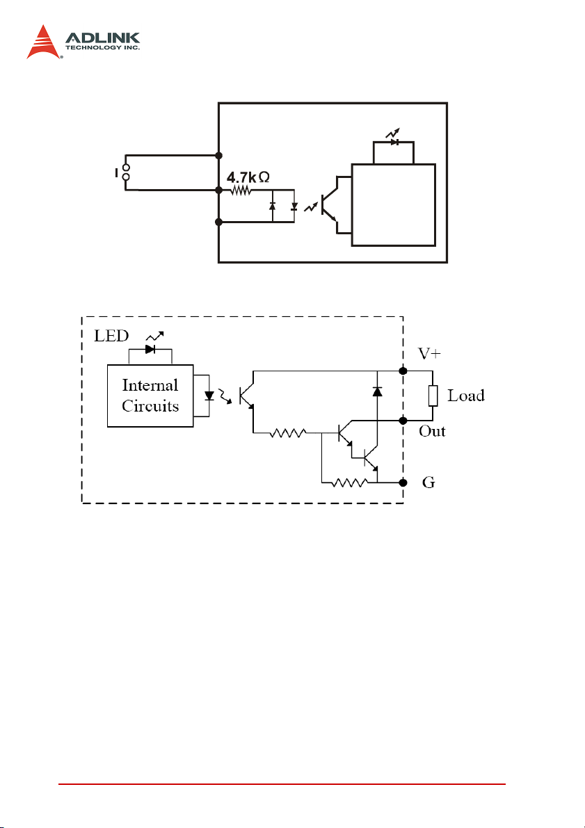
-P Wet Contact Input
-N NPN Sinking Output
v+
IN
G
LED
Internal
Circuits
46 HSL Slave Module
Page 60

-P PNP Sourcing Output
A
S
S
A
-R Relay Output
LED
NO.n
Internal
Circuit
SSR
COM.n
Analog Input (Differential Voltage Input)
Differential
ignal
ource
IN(+)
IN(-)
<30V
GND
Load
DC
HSL Slave Module 47
Page 61

Analog Input (Single-End Voltage Input)
A
A
y
A
A
A
Ground
Signal
Source
IN(+)
GND
Analog Input (Current Measure)
Current
Source
IN(+)
R
IN(-)
R=125 Ohm
%1 accurac
Thermocouple Measurement
DC
DC
IN(+)
DC
IN(-)
<30V
GND
48 HSL Slave Module
Page 62

Dimension
-DB Daughterboard form factor (100 mm X 78.2 mm)
-M Daughterboard with aluminum cover (125 mm X 80 mm)
HSL Slave Module 49
Page 63
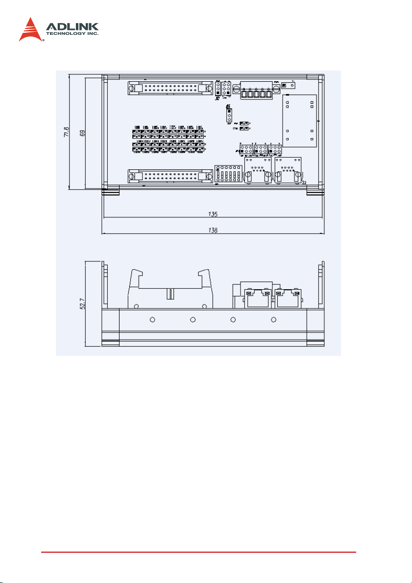
-U U-series slave I/O module (71.8 mm X 138 mm)
50 HSL Slave Module
Page 64

3.2 Terminal Base
Available terminal bases include:
X HSL-TB32-U-DIN
X HSL-TB64-DIN
X HSL-TB32-M-DIN
X HSL-TB32-MD
Features
X Field I/O wiring connection for HSL I/O modules
X Screw- or spring-type terminal for easy field wiring
X Power and ground connections for each signal channel
X Interlocking design for installation in rugged environments
X Power LED indicator
X DIN rail mounting
X Onboard terminator resistor
3.2.1 General Description
Model Name Specifications Supports
(1): 32 channels direct connected terminal base
(2): One DB slot
(1): 64 channels direct connected terminal base
(2): Two DB slots
32 channels direct connected terminal base for
HSL M-series module
For DB Series
For M Series
HSL-TB32-U
HSL-TB64
HSL-TB32-M
HSL-TB32-MD
All HSL DB-series modules
All HSL DB-series modules
All HSL M-series modules
HSL Slave Module 51
Page 65

3.2.2 Jumper Settings
Since HSL is a serial transmission system, a terminator must be
placed at the end of the cable. Each TB has an onboard jumper
selectable terminator. The terminator must be enable only by
the last module.
52 HSL Slave Module
Page 66

3.2.3 HSL-TB32-MD Jumper Settings
HSL Slave Module 53
Page 67

3.2.4 Dimensions
-DB with HSL-TB32-U-DIN (126 mm x 120.1 mm x 107.3 mm)
-DB with HSL-TB64-DIN (168.7 mm x 120.1 mm x 107.3 mm)
54 HSL Slave Module
Page 68

-M module with HSL-TB32-M-DIN (128.5 mm x 85.5 mm x 108
mm)
-HSL-TB32-MD (129 mm x 107 mm)
HSL Slave Module 55
Page 69

3.3 HSL-HUB/Repeater
Available HSL-HUB/Repeater includes:
X HSL-HUB
X HSL-Repeater
Features
X Master to HUB, HUB to HUB, HUB to Slave link styles
X Supports T-bracing connection/Star connection (subsystem
concept)
X Supports up to 2.4 km wiring distance via seven HSL-HUB/
Repeater modules
X One input port with three output segment ports
X Jumper configurable 3/6/12 Mbps transmission speed
X Jumper configurable full and half duplex transmission
modes
X RJ-45 phone jack for easy installation
X 24 VDC input
3.3.1 General Description
56 HSL Slave Module
Page 70

3.3.2 Jumper Setting
FD/HD setting JP*(0 to 3), JFH1
3/6/12 Mbps setting: JBPS1
HSL Slave Module 57
Page 71

3.3.3 Dimensions
HSL-HUB
HSL-Repeater
58 HSL Slave Module
Page 72

3.4 Managing Slave Index in an HSL Network
3.4.1 Before you proceed
Before powering on the slave modules, you have to adjust the DIP
switch. For more information, refer to section 3.1.6. Take note of
the following:
1. A master controller can connect up to 63 slave indexes.
For example, the PCI-7852 has two master controllers.
Therefore, it supports a maximum 126 slave indexes.
2. The more compact the slave addresses are in an HSL
network, the greater efficiency.
3. Observe the discrete I/O and relay module rule.
Module
HSL-DI16DO16-M-NN/NP/PN/PP
HSL-DI16DO16-DB-NN/NP/PN/PP
HSL-R8DI16-M-N/P
HSL-DI8-L-N/P
HSL-DO8-L-N/P
HSL-DI4DO4-L-NN/NP/PN/PP
HSL-DI16-UL
HSL-DI16DO16-UJ/US
HSL-DI32-M-N/P
HSL-DI32-DB-N/P
HSL-DO32-M-N/P
HSL-DO32-DB-N/P
Slave Index
Occupation
1 (Any address)
2 (Consecutive
from odd number)
Transmission
Mode
Full Duplex (Fixed) 6 Mbps (Fixed)
4. Observe the analog I/O and thermocouple module rule.
Module
HSL-AI16AO2-M-VV
HSL-AI16AO2-M-AV
HSL-AO4-U
Slave Index
Occupation
2 (Leap number) Full Duplex (Fixed)
Transmission
Mode
Transmission
Speed
Transmission
Speed
3/6/12 Mbps
Selectable
HSL Slave Module 59
Page 73

Observe the motion control module rule
Module
HSL-4XMO-CG-N/P
HSL-4XMO-CD-N/P
5. Special rules
Z If you will install only one HSL-AI16AO2-M-VV or HSL-
AI16AO2-M-AV and the DIP switch is set to 1 (HSLAI16AO2-M-VV/AV only supports full duplex mode), the
occupied indexes will be 1 and 3. You must assign the
parameter “max_slave_No” of HSL_start(…) as 4 to
ensure correct communication. You may ignore this rule
when using the HSL_auto_start function.
Z If you will install only one HSL-4XMO-CG-N/P or HSL-
4XMO-CD-N/P and the DIP switch is set as to 1 and full
duplex mode, the occupied indexes will be 1, 3, 5, and 7.
You must assign the parameter “max_slave_No” of
HSL_start(…) as 8 to ensure correct communication.
You may ignore this rule when using the HSL_auto_start
function. In half duplex mode, these modules occupy 1,
2, 3 and 4. Therefore, you must assign the
“max_slave_No” of HSL_start(…) as 4 or call the
HSL_auto_start function.
Slave Index
Occupation
4 (Leap) / 4(Con-
secutive)
Transmission
Mode
Full Duplex / Half
Duplex
Transmission
Speed
3/6/12 Mbps
Selectable
60 HSL Slave Module
Page 74

3.4.2 Examples
The following examples are provided for user reference. All modules used are set in full duplex mode.
Example 1
Provided you installed two HSL-DI16DO16, two HSL-DI32-MN, and an HSL-AI16AO2-VV with all slave modules in full
duplex mode, you can have two conditions as follows:
Condition 1: HSL-AI16AO2-VV operates at 6 Mbps.
We recommended that you use the provided slave index configuration.
Item DIP Switch Index Occupation in HSL
HSL-DI32-M-N #1 1 1, 2
HSL-DI32-M-N #2 3 3, 4
HSL-AI16AO2-VV 5 5, 7
HSL-DI16DO16 #1 6 6
HSL-DI16DO16 #2 8 8
This is an example of a compact composition. The scan time
needs 30.33 µs x 8 at 6 Mbps, full duplex mode. Users can
connect the modules with one master controller.
Condition 2: HSL-AI16AO2-VV operates at 12 Mbps.
We recommended that you use the provided slave index configuration.
Item DIP Switch Index Occupation in HSL
HSL-DI32-M-N #1 1 1, 2
HSL-DI32-M-N #2 3 3, 4
HSL-DI16DO16 #1 5 5
HSL-DI16DO16 #2 6 6
Another example of a compact composition. The scan time needs
30.33 µs x 6 at 6 Mbps, full duplex mode. You may connect these
modules with one master controller. The HSL-AI16AO2-M-VV
module connects to another master controller. The DIP switch of
HSL Slave Module 61
Page 75

HSL-AI6AO2-M-VV is assigned as 1. Because of the special rule,
users have to assign the “max_slave_No” of HSL_start(…) as 3 or
call HSL_auto_start by connect_index #1. The illustration below
explains this.
HSL-DI16DO16
Consequently, the cycle time of the first master controller is
30.33µs x 6 and the cycle time of the second master controller is
45.5 µs at 12 Mbps, full duplex mode.
62 HSL Slave Module
Page 76

Example 2
Provided you installed two HSL-DI16DO16-UJ, one HSLDI16DO16-M-NN, two HSL-DO32-M-N, one HSL-AI16AO2-VV,
and two HSL-4XMO-CG-N with all slave modules in full duplex
mode, you can have the following conditions:
Condition 1: The HSL-AI16AO2-VV and two HSL-4XMO-CGN operate in 6 Mbps.
We recommended that you use the provided slave index configuration.
Item DIP Switch Index Occupation in HSL
HSL-4XMO-CG-N #1 1 1, 3, 5, 7
HSL-4XMO-CG-N #2 2 2, 4, 6, 8
HSL-DO32-M-N #1 9 9, 10
HSL-DO32-M-N #2 11 11, 12
HSL-AI16AO2M-VV 13 13, 15
HSL-DI16DO16-UJ #1 14 14
HSL-DI16DO16-UJ #2 16 16
HSL-DI16DO16-M-NN 17 17
The scan time needs 30.33µ x 17 at 6 Mbps, full duplex mode.
You can connect these modules with one master controller.
Condition 2: An HSL-AI16AO2-VV and two HSL-4XMO-CG-N
modules operate at 12 Mbps.
We recommended that you use the provided slave index configuration.
Group 1 DIP Switch Index Occupation in HSL
HSL-DO32-M-N #1 1 1, 2
HSL-DO32-M-N #2 3 3, 4
HSL-DI16DO16-UJ #1 5 5
HSL-DI16DO16-UJ #2 6 6
HSL-DI16DO16-M-NN 7 7
The scan time needs 30.33µs x 7. You may connect these
modules with one master controller. The HSL-AI16AO2-M-VV
HSL Slave Module 63
Page 77

and two HSL-4XMO-CG-N modules connect to another master
controller. The management table below is for reference.
Group 2 DIP Switch Index Occupation in HSL
HSL-4XMO-CG-N #1 1 1, 3, 5, 7
HSL-4XMO-CG-N #2 2 2, 4, 6, 8
HSL-AI16AO2-M-VV 9 9, 11
Refer to the illustration below.
The cycle time of the first master controller is 30.33µs x 7,
while the cycle time of second master controller is 15.17µs x 11
at 12 Mbps, full duplex mode.
64 HSL Slave Module
Page 78

4 HSL LinkMaster Utility
After installing the master controller and slave modules, you are
now ready to install the HSL driver and the LinkMaster utility for
system testing and debugging. This utility features a user-friendly
interface that enables you to easily test I/O statuses, including
read/write the I/O data, calibration and motion control. It is recommended that you use this utility before implementing the whole
system.
HSL LinkMaster Utility 65
Page 79

4.1 Software Installation
You can install the HSL drivers from the ADLINK All-in-One CD
that comes with the package or you may download the drivers
from the ADLINK website. The latest driver version are available
from the website.
To install the HSL drivers:
1. Locate, then double-click the SETUP.exe file from the
All-in-One CD. The installation window appears. Click
Next.
2. Follow screen instruction to install.
3. Restart the system when the installation process is completed.
66 HSL LinkMaster Utility
Page 80

4.2 ADLINK HSL LinkMaster Utility
4.2.1 Launching the LinkMaster Utility
After installing the drivers, click Start > PCI-7853 > LinkMaster to
launch the LinkMaster utility. The main window appears.
4.2.2 Before you proceed
1. LinkMaster is a testing and debugging program based
on VB 6.0 and is only available for Windows® 98/NT/
2000/XP environments with a monitor that has a screen
resolution of 800x600 or higher. The utility does not support DOS environment.
2. The LinkMaster version control may be found on the top-
right corner of the main window.
3. Any slave modules may be tested with this utility, includ-
ing discrete I/O, analog I/O, thermocouple module, and
motion control modules. For motion control utility and
manipulation, refer to the HSL-4XMO user’s manual.
HSL LinkMaster Utility 67
Page 81

4.2.3 LinkMaster Utility Introduction
Below is the LinkMaster main user interface labeled according to
function.
X A. Select card
X B. Network quality test
X C. Set hub number (Only for 7853/54)
X D. Set duplex mode (Only for 7853/54)
X E. Set speed mode (Only for 7853/54)
X F. General slave selection
X G. Auto scan slave modules
X H. Show software information
X I. Show module information
68 HSL LinkMaster Utility
Page 82

X J. Test slave module
X K. Exit motion creator
X L. Version information
Below are descriptions of the main interface buttons.
1. Current Select Card ID. When LinkMaster is activated,
it searches all HSL master control cards installed in the
system, such as PCI-7853, PCI-7854 and PMC-7852/G.
Every card shows its index (ID) ranging from 0 to?. You
can use this function to specify which card you want to
operate.
2. Current Select Connect Index. For cards with two mas-
ter controllers such as PCI-7854 and PMC-7852/G, the
connect index ranges from 0 to 1. For single master controller such as PCI-7853, the connect index is 0. Refer to
the diagram below.
3. ALL Slave ID Connection Test. The screen capture
below shows a live scan of all I/O modules for network
quality test. The LinkMaster lets you check the network
environment.
Start the test by clicking on the Test button. Press Stop to stop
scanning. When you start the test, the utility continuously tests
each ID and shows the module type to left-column labels. Rightcolumn labels show the counter for communication error.
HSL LinkMaster Utility 69
Page 83

4. Connect/Auto Scan. Clicking this button allows the utility to scan all slave modules connected to the master
card with specified connect index. The utility shows all
the slave modules’ information including the address
and slave type within the 9th block.
5. Slaves Disconnect. Click this to stop the utility from
scanning all the slave modules and to disconnect them.
6. Status Msg. Checks if the slave modules are connected
or disconnected.
Test Slave: While all connected slave modules list in 9th
block, you can use this function to activate the testing dialog. For example, when you connect the HSL-DI16DO16-MNN, you will see this module from the screen. Clicking on it
will show a window from where you can test and debug the
modules.
7. Exit. Click to close the utility.
8. About. Shows the DLL version information.
The succeeding sections outline the usage of the slave module
utility.
70 HSL LinkMaster Utility
Page 84

4.2.4 HSL-DI16DO16 Utility
1. Slave Address. Shows the slave index occupied by the
module.
2. Digital Input. A white circle indicates no digital input; a
red icon indicates that the digital input is not activated.
3. Digital Output. Click on the icon to activate the digital
output. Red icon indicates that the digital output is turned
on, and vice-versa.
4. Slave Status: Shows the communication status between
the slave module and the master card. The functions
definition are enumerated below.
Z Bit 0 is Data_Req bit.
Z Bit 2 is for CHK1. When Bit2 is equal to 1, a communica-
tion error occurred once).
Z Bit 3 is for CHK3. When Bit3 is equal to 1, a communica-
tion error occurred three times.
Z Bit 4, Bit 5 and Bit 6 bits are for CHK7. WhenBit4, Bit5,
and Bit6 are all equal to 1, a communication error
occurred seven times.
HSL LinkMaster Utility 71
Page 85

4.2.5 HSL-DI32 and HSL-DO32 Utility
1. Slave Address. Shows the slave index occupied by the
module. These modules occupy two slave indexes starting from an odd number. For example, when you adjust
the DIP switch to 3, the modules are assigned indexes 3
and 5.
2. Digital Input. A white circle indicates no digital input; a
red icon indicates that the digital input is not activated.
3. Digital Output. Click on the icon to activate the digital
output. Red icon indicates that the digital output is turned
on, and vice-versa.
4. Slave Status: Shows the communication status between
the slave module and the master card. The functions
definition are enumerated below.
Z Bit 0 is Data_Req bit.
Z Bit 2 is for CHK1. When Bit2 is equal to 1, a communica-
tion error occurred once).
Z Bit 3 is for CHK3. When Bit3 is equal to 1, a communica-
tion error occurred three times.
Z Bit 4, Bit 5 and Bit 6 bits are for CHK7. WhenBit4, Bit5,
and Bit6 are all equal to 1, a communication error
occurred seven times.
72 HSL LinkMaster Utility
Page 86

4.2.6 HSL-DI8/HSL-DO8/HSL-DI4DO4 Utility
1. Slave Address. Shows the slave index occupied by the
module. These modules occupy only one slave index.
2. Digital Input. A white circle indicates no digital input; a
red icon indicates that the digital input is not activated.
3. Digital Output. Click on the icon to activate the digital
output. Red icon indicates that the digital output is turned
on, and vice-versa.
4. Slave Status: Shows the communication status between
the slave module and the master card. The functions
definition are enumerated below.
Z Bit 0 is Data_Req bit.
Z Bit 2 is for CHK1. When Bit2 is equal to 1, a communica-
tion error occurred once).
Z Bit 3 is for CHK3. When Bit3 is equal to 1, a communica-
tion error occurred three times.
Z Bit 4, Bit 5 and Bit 6 bits are for CHK7. WhenBit4, Bit5,
and Bit6 are all equal to 1, a communication error
occurred seven times.
HSL LinkMaster Utility 73
Page 87

4.2.7 HSL-R8DI16 Utility
1. Slave Address. Shows the slave index occupied by the
module. These modules occupy only one slave index.
2. Digital Input. A white circle indicates no digital input; a
red icon indicates that the digital input is not activated.
3. Digital Output. Click the icon to activate digital output.
This function turns the relay ON or OFF. A red circle indicates that the relay is on, and vice versa.
4. Slave Status: Shows the communication status between
the slave module and the master card. The functions
definition are enumerated below.
Z Bit 0 is Data_Req bit.
Z Bit 2 is for CHK1. When Bit2 is equal to 1, a communica-
tion error occurred once).
Z Bit 3 is for CHK3. When Bit3 is equal to 1, a communica-
tion error occurred three times.
Z Bit 4, Bit 5 and Bit 6 bits are for CHK7. WhenBit4, Bit5,
and Bit6 are all equal to 1, a communication error
occurred seven times.
74 HSL LinkMaster Utility
Page 88

4.2.8 HSL-AI16AO2 Utility
1. Slave Address. Shows the slave index occupied by the
module. The module occupies two consecutive indexes.
For example, when you adjust the DIP switch to 4, the
module obtains slave indexes 4 and 6.
2. Signal Type. Indicates the module’s signal type.
3. Signal Range. Allows selection of the signal range. The
utility offers four ranges including ±10V, ±5V, ±2.5V and
±1.25V for HSL-AI16AO2-M-VV. For HSL-AI16AO2-MAV, the signal ranges are 20 mA, 10 mA, and 5 mA.
4. Firmware Version. Shows the latest firmware version.
5. AO Function. Key in the analog output value in the text
box, then press SEND to trigger the AO. The range is
±10 V.
6. Configuration. Allows you to check if the signal range is
correct before clicking on the Start Read button. The
Configuration button allows you to save the information
and complete the configuration task.
7. Start Read. Enables the A/D conversion task to read
back the analog input values. The values are shown in
the 12th block.
8. Stop Read. Disables the A/D conversion task.
HSL LinkMaster Utility 75
Page 89

9. Calibration. Calibrates the module. The modules are
shipped with correct calibration. Refer to Appendix C if
you want to recalibrate the module.
10.Exit. Closes the utility.
11. Slave Status: Shows the communication status between
the slave module and the master card. The functions
definition are enumerated below.
Z Bit 0 is Data_Req bit.
Z Bit 2 is for CHK1. When Bit2 is equal to 1, a communica-
tion error occurred once).
Z Bit 3 is for CHK3. When Bit3 is equal to 1, a communica-
tion error occurred three times.
Z Bit 4, Bit 5 and Bit 6 bits are for CHK7. WhenBit4, Bit5,
and Bit6 are all equal to 1, a communication error
occurred seven times.
4.2.9 HSL-4XMO Utility
Refer to the HSL-4XMO user’s manual.
76 HSL LinkMaster Utility
Page 90

5 HSL Function Library
This chapter describes the functions for developing programs in C,
C++, or Visual Basic.
5.1 List of Functions
This section presents all the functions. The function prototypes
and common data types are declared in HSL.h. It is recommended
that you use these data types in your application programs. The
following table shows the data type names and their ranges.
Type N a m e Description Range
U8 8-bit ASCII character 0 to 255
I16 16-bit signed integer -32768 to 32767
U16 16-bit unsigned integer 0 to 65535
I32 32-bit signed long integer -2147483648 to 2147483647
U32 32-bit unsigned long integer 0 to 4294967295
F32 32-bit single-precision floating-point -3.402823E38 to 3.402823E38
F64 64-bit double-precision floating-point
Boolean Boolean logic value TRUE, FALSE
All HSL function calls were revised. Refer to the mapping table in
Appendix B. All function calls have the same prefix HSL_. The
function belonging to a system level purpose has the following
form:
HSL_{action_name}. e.g. HSL_initial().
-1.797683134862315E308
to 1.797683134862315E309
If they belong to a discrete I/O module purpose, the function is as
follows:
HSL_D_{action_name}. e.g. HSL_D_read_input()
If they belong to an analog I/O module purpose, the function is as
follows.
HSL_A_{action_name}. e.g. HSL_A_write_output().
If they belong to a motion control module purpose, the function is
as follows.
HSL_M_{action_name}. e.g. HSL_M_start_tr_move().
HSL Function Library 77
Page 91

For the motion control library description, refer to the HSL-4XMO
function library manual. This section contains the system level
function, discrete I/O control, and analog I/O control.
Initialization and System Information, Section 5.2
Function Name Description
HSL_initial Master card initialization
Initialize by system automatically (sw_enable=0) or
HSL_intial_sw
HSL_close Release all resources occupied by master card
HSL_start
HSL_auto_start
HSL_stop Stop scanning the connected slave modules
HSL_set_scan_condition Set scanning conditions (only for 7853/54)
HSL_get_scan_condition Get scanning conditions (only for 7853/54)
HSL_connect_status
HSL_slave_live Get the module status of the slave module
HSL_get_irq_channel Get the IRQ occupied by master card
manually via the S1 dip switch (sw_enable=1)
(7853/54 only)
Start to scan all the slave modules connected to
master card
Start to scan and automatically detect all the slave
modules connected to master card
Get the communication status of the specified
slave module
Timer Control, Section 5.3
Function Name Description
HSL_enable_timer_interrupt
HSL_disable_timer_interrupt
HSL_set_timer Set the resolution of timer (For 7851/52)
HSL_set_int_timer Set the timer parameters (For 7853/54)
HSL_set_int_timer_enable
HSL_wait_timer_interrupt Wait timer event (For 7853/54)
78 HSL Function Library
Enable timer interrupt of master card (For 7851/
52)
Disable timer interrupt of master card (For 7851/
52)
Enable/Disable timer interrupt of master card (For
7853/54)
Page 92

Discrete I/O, Section 5.4
Function Name Description
HSL_D_read_input Read back all discrete I/O with unsigned 32-bit
HSL_D_read_channel_input Read back discrete I/O by channel selection
HSL_D_write_output Write all discrete I/O with unsigned 32-bit
HSL_D_write_channel_output Write discrete I/O by channel selection
HSL_D_read_ouput Read back the output value stored in RAM
HSL_D_read_all_slave_input Read back all inputs of slave modules
HSL_D_write_all_slave_output Write all outputs of slave modules
HSL_D_set_input_logic Set the logic of digital input
HSL_D_set_output_logic Set the logic of digital output
HSL_D_set_int_renewal_type Set DI renewal check type (Only for 7853/54)
HSL_D_set_int_renewal_bit
HSL_D_set_int_control
HSL_D_wait_di_interrupt Wait DI renewal event(Only for 7853/54)
Set the data bits of DI renewal check for each
slave (Only for 7853/54)
Set DI interrupt enable or disable (Only for
7853/54)
Analog I/O, Section 5.5
Function Name Description
HSL_A_start_read Start A/D conversion.
HSL_A_stop_read Stop A/D conversion
HSL_A_set_signal_range Set the signal range of analog input channels
HSL_A_get_signal_range Get the signal range of analog input channels
HSL_A_get_input_mode Get the signal input mode
HSL_A_set_last_channel Set the last channel of analog input channels
HSL_A_get_last_channel Get the last channel of analog input channels
HSL_A_read_input Read back the value of analog input channels
HSL_A_write_output Send out the analog output
HSL_A_read_output Read back the analog output data
HSL_A_sync_rw Read and write the data synchronously
HSL_A_get_version Get the kernel version of analog I/O module
HSL Function Library 79
Page 93

Pulse Stretcher Function (HSL-DI16-UL only), Section 5.6
Function Name Description
HSL_D_set_di_latch_function Set DI-ltech function for one channel
HSL_D_set_di_latch_functionA Set DI-latch function for all channels
HSL_D_get_di_latch_function Retrieve DI-latch function
80 HSL Function Library
Page 94

5.2 Initialization and System Information
@ Name
HSL_initial – Master board initialization
HSL_close – Release all resource occupied by master board
HSL_start – Start to scan all slave module connected to master
board
HSL_auto_start – Start to scan and automatically detect all the
slave modules connected to master card
HSL_stop –Stop scanning the connected slave modules
HSL_set_scan_condition – Set scanning conditions (7853/54
only)
HSL_get_scan_condition – Get scanning conditions (7853/54
only)
HSL_connect_status – Get the communication status of the
specified slave module
HSL_slave_live – Get the module status of the slave module
HSL_get_irq_channel – Get the IRQ occupied by master card
@ Description
HSL_initial:
Initializes the hardware and software states of the HSL master
card (PCI-7851/52 or PMC-7852/G). You can check the return
code of this function to know if the initialization is successful or
not. Since the HSL master card is plug-and-play, the base address
and IRQ level are automatically assigned by the BIOS.
HSL_close:
Releases the resource occupied by the HSL master card. When
terminating the program, do not forget to call this function to
release all the resource occupied by the HSL master card.
HSL_start:
Scans the total connected slave modules. You can assign the
number of slave indexes the HSL master board will scan.
HSL Function Library 81
Page 95

HSL_auto_start:
Automatically detects the total connected slave modules. Every
master controller can connect up to 63 slave indexes.
HSL_stop:
Stops scanning the connected slave modules.
HSL_set_scan_condition:
Assigns the scan rate (3/6/12 Mbps) and communication types
(full or half duplex). This function needs to be set up between the
function HSL_initial and HSL_start.
HSL_get_scan_condition:
By this function, User can get the settings of communication types
and scan rate which are set by “HSL_set_scan_condition”.
HSL_connect_status:
This function is used to check the communication status between
master board and slave modules.
HSL_slave_live:
This function is used to check the status of the slave module (live
or die).
HSL_ get_irq_channel:
This function is used to get IRQ assigned by system.
@ Syntax
C/C++ (DOS, Windows 98/NT/2K/XP)
I16 HSL_initial (U16 card_ID);
I16 HSL_close (U16 card_ID);
I16 HSL_start (U16 card_ID, U16 connect_index,
U16 max_slave_No);
I16 HSL_auto_start (U16 card_ID, U16
connect_index);
I16 HSL_stop (U16 card_ID, U16 connect_index);
I16 HSL_set_scan_condition(I16 card_ID, I16
connect_index, I16 comm_type, I16
transfer_rate, I16 hub_number);
82 HSL Function Library
Page 96

I16 HSL_get_scan_condition(I16 card_ID, I16
connect_index, I16 *comm_type, I16
*transfer_rate, I16 *hub_number);
I16 HSL_connect_status (U16 card_ID, U16
connect_index, U16 slave_No, U8 *sts_data);
I16 HSL_slave_live (U16 card_ID, U16
connect_index, U16 slave_No, U8 *live_data);
void HSL_get_irq_channel (I16 card_ID, I16
*irq_no);
Visual Basic (Windows 98/NT/2K/XP)
HSL_initial (ByVal card_ID As Integer) As Integer
HSL_close (ByVal card_ID As Integer) As Integer
HSL_start (ByVal card_ID As Integer, ByVal
connect_index As Integer, ByVal max_slave_No
As Integer) As Integer
HSL_auto_start (ByVal card_ID As Integer, ByVal
connect_index As Integer) As Integer
HSL_stop (ByVal card_ID As Integer, ByVal
connect_index As Integer) As Integer
HSL_set_scan_condition(ByVal card_ID As Integer,
ByVal connect_index As Integer, ByVal
comm_type As Integer, ByVal transfer_rate As
Integer, ByVal hub_number As Integer);
HSL_get_scan_condition((ByVal card_ID As Integer,
ByVal connect_index As Integer, comm_type As
Integer, transfer_rate As Integer,
hub_number As Integer);
HSL_connect_status (ByVal card_ID As Integer,
ByVal connect_index As Integer, ByVal
slave_No As Integer, sts_data as Byte) As
Integer
HSL_slave_live (ByVal card_ID As Integer, ByVal
connect_index As Integer, ByVal slave_No as
Integer, live_data as Byte) As Integer
HSL_get_irq_channel (ByVal card_ID As Integer,
irq_no As Integer) As Integer
@ Argument
card_ID: Specify the HSL master card index. Normally, the board
index sequence would be decided by the system. The index is
from 0.
HSL Function Library 83
Page 97

connect_index: For PCI-7851, the valid value is 0. For PCI7852 and PMC-7852/G, the valid value is 0 or 1.
max_slave_No: The maximum slave index connected to the HSL
master card with the connect_index. The valid value is from 1 to
63.
slave_No: Specifiy the slave module with slave index which want
to perform this function. The valid value is from 1 to 63.
comm_type: Half or Full duplex
0: Half duplex
1: Full duplex
transfer_rate: transfer rate setting
1: 3M
2: 6M
3: 12M
hub_number: cascaded Hub number. If no Hub in the system, the
value of hub_number is set to 0.
*sts_data: The communication status of this slave module. The
definition is as follows.
X Bit 0 is Data_Req bit.
X Bit 2 is for CHK1. (If Bit2 is 1. It means that there is 1 time
communication error).
X Bit 3 is for CHK3. (If Bit3 is 1. It means that there are 3 times
communication errors).
X Bit 4, BIT 5 and BIT 6 bits are for CHK7. (If Bit4, Bit5 and
Bit6 all are 1. It means that there are 7 times communication
errors).
*live_data: The module status.
X 1: the module is live
X 0: the module is die.
irq_no: IRQ occupied by master card.
84 HSL Function Library
Page 98

@ Return Code
ERR_No_Error
ERR_Open_Driver_Fail
ERR_Invalid_Board_Number
ERR_Satellite_Number
ERR_Connect_Index
HSL Function Library 85
Page 99

5.3 Timer Control
@ Name
HSL_enable_timer_interrupt (7851/52 only) – Enable timer
interrupt of master card
HSL_disable_timer_interrupt (7851/52 only) – Disable
timer interrupt of master card
HSL_set_timer (7851/52 only)– Set the resolution of timer
HSL_set_int_timer (7853/54 only) – Set the timer parameters
HSL_set_int_timer_enable (7853/54 only) – Enable\Disable
timer interrupt of master card( 7853/54 only)
HSL_wait_timer_interrupt (7853/54 only) – Wait timer event
@ Description
HSL_enable_timer_interrupt (7851/52 only):
Enables the hardware timer interrupt of the master card.
HSL_disable_timer_interrupt (7851/52 only):
Disables the hardware timer interrupt of the master card.
HSL_set_timer (7851/52 only):
This function sets up Timer 1 and Timer 2. Timer 1 and Timer 2 are
used as frequency dividers to generate a dedicated constant timer
interrupt sampling rate. The highest timer interrupt sampling rate
of the master card may not exceed 20 KHz on Windows NT platform because of system limitation. The following example is set at
6 Mbps:
If you want to have a sampling rate of 15 kHz, the function must be
HSL_set_timer (0, 20, 20)
If you want to have a sampling rate of 1.2 kHz, the function must
be
HSL_set_timer (0, 100, 50)
The formula used is:
Transmission speed / (c1 x c2)
86 HSL Function Library
Page 100

In addition, the values of c1 and c2 must be greater than 1. When
c1=0 or c2=0, the timer interrupt stops.
HSL_set_int_timer (7853/54 only):
Sets up the Timer parameter p1. The timer is used as frequency
divider to generate a dedicated constant timer interrupt sampling
rate.
MHz
The formula is: Frequency(Hz) =
48
)11(256
+⋅ p
HSL_set_int_timer_enable (7853/54 only):
Enables or disables the hardware timer interrupt of this master
card.
HSL_wait_timer_interrupt (7853/54 only):
Waits for the specific interrupt when you enabled the interrupt
function by HSL_set_int_timer_enable() and set the timer parameter p1 by HSL_set_int_timer(). When this function is running, the
process never stops even if it is triggered or the function has timed
out. The following codes illustrate this function.
I16 ret;
HSL_set_int_timer(0, 0xffff); // set the
parameter p1
HSL_set_int_timer_enable(0, 1); //enable the
timer
for(int i = 0; i< 10; i++)
{
ret = HSL_wait_timer_interrupt(g_cardId,
10000);
if(ret == 0)
// do something…
else
// time out
}
HSL Function Library 87
 Loading...