


Contents: Page:
Home
Part 2: Insta llati on Cl. 89 67
1. General Information
1.1 Machine Operation without Material . . . . . . . . . . . . . . . . . . . . 3
1.2 Table Tops . . . . . . . . . . . . . . . . . . . . . . . . . . . . . . . . . . 3
2. Frame Ass em bly
3. Table Top, Completing and Screwing on
4. Connecting the Sewing Drive to the Table Top
4.1 General . . . . . . . . . . . . . . . . . . . . . . . . . . . . . . . . . . . . 8
4.2 Drive Mounting . . . . . . . . . . . . . . . . . . . . . . . . . . . . . . . . 8
4.3 Voltage Compensation Motor/ M achine Head . . . . . . . . . . . . . . . 8
4.4 Attaching the Pedal and Rod . . . . . . . . . . . . . . . . . . . . . . . . 9
4.5 Electrical Co nnection of the Motors . . . . . . . . . . . . . . . . . . . . . 9
5. Attaching the Machine Head
5.1 Mounti ng the Sewing Head, Establishing the Voltage Compensation
Positioning the V-belt . . . . . . . . . . . . . . . . . . . . . . . . . . . . 10
5.2 Attaching the Belt Guard,
Mounting and Setting the Synchronizer . . . . . . . . . . . . . . . . . . 11
5.3 . Con necting the Sol enoid Valve Strip . . . . . . . . . . . . . . . . . . . . 12
6. Connecting the Compressed Air Maintenance Unit
7. Filling Oil and Readying the Machine for Operation
8. Conducting the Sewing Test
. . . . . . . . . . . . . . . . . . . . . . . . . . . . . . 6
. . . . . . . . . . . . . . . . 7
. . . . . . . . . . 13
. . . . . . . . . . 14
. . . . . . . . . . . . . . . . . . . . . . . . 14
GB

1. General Information
Attention!
The mains voltage and the nominal voltage listed on the
motor identification plate must be the same.
All work on the electronics is to be conducted only by authorized personnel and with the mains plug disconnected.
Please observe all safety instructions!
Installation is to be conduct ed according to th e following
instructions. A l l necessary parts are to be foun d i n the enclosed package.
1.1 Machine Operation without Material
Attention!
First arrest the pressure feet in the raised position and
set the shortest pressure foot stroke.
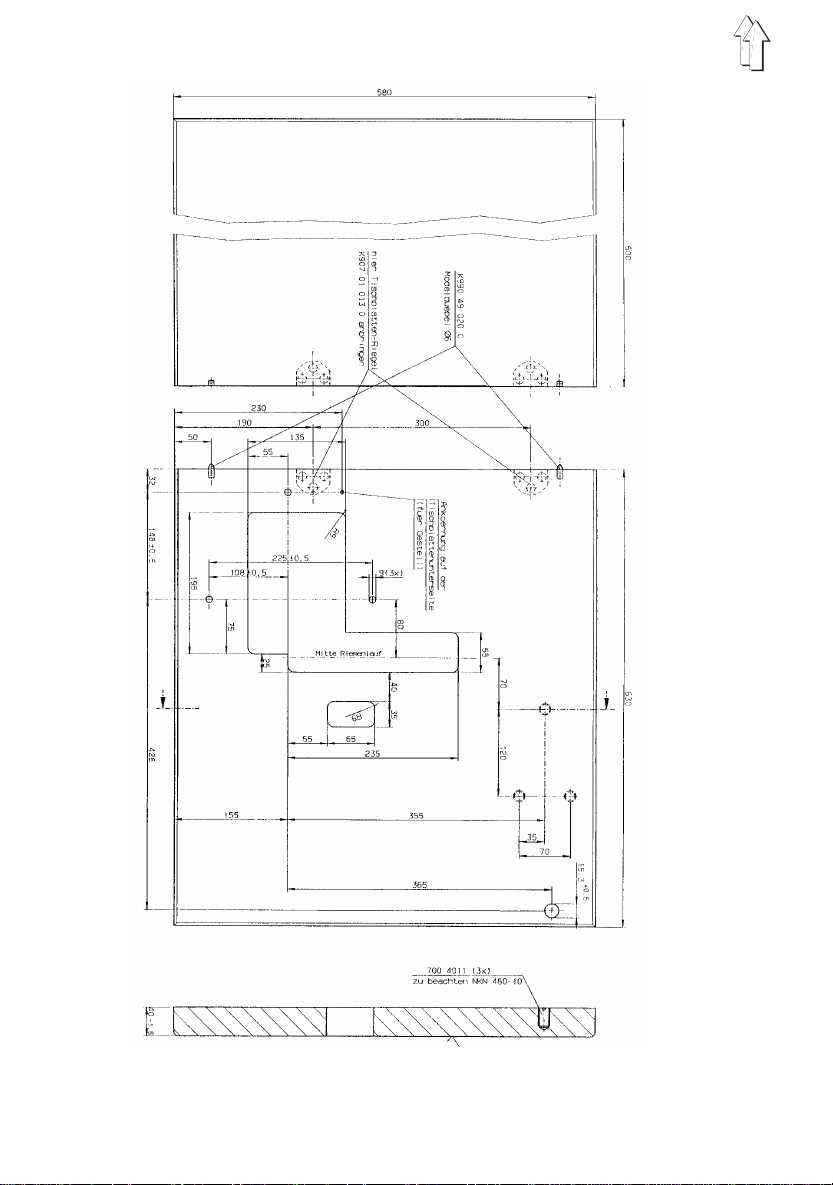
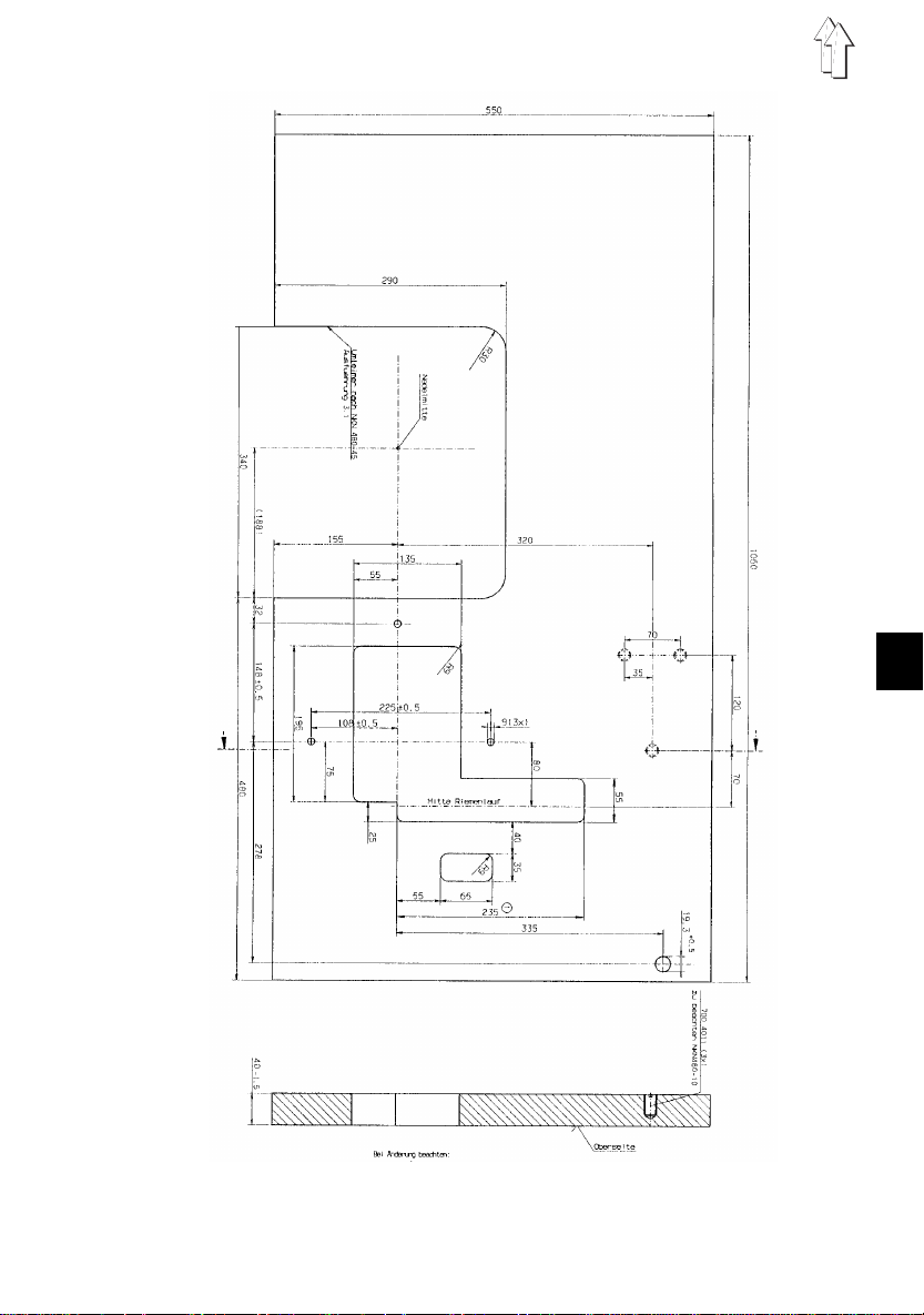
1.2 T able Tops
The cutouts in self-made table tops must have the dimensions shown in the sketches on pages 4 and 5.
The table to ps must have the necessary load ca pacity
and firmness .
GB
3
4
GB
5

2. Frame Assembly
–
Assemble the f rame parts as show n and take care
that all feet touch the floor.
–
Adjust the screws on the frame foot at the right back
accordingly for this.
6

3. T able Top, Completing and Screwing on
1
6
5
23
4
GB
Underside of the Table Top:
- Scr ew on the cable duct 4 and the holder 5 for strain re-
- Scr ew on main switch 2
- Scr ew on the sewing l i ght transformer 1, if supplied
- Lay the electric wiring in the cable duct and to the motor
- Screw on the drawer 3 with mounting
- Screw on table top support plate 6 by frame MG56-2
- Screw the table top onto the frame with B8 x 35 wood
liever
screws.
7

4. Connecting the Sewing Drive to the Table Top
4.1 General
Different dr i ve and connections packages are availa ble
for the machine.
The drive package consists of:
Motor, motor protection switch with wiring, belt, belt pul-
ley.
The connectios package contains all wiring between the
motor and th e sewing head.
The direct current drive available for this machine is ope-
rated by a "monophase alternating voltage". Therefore,
with multiple machines, the connections must be uniformly distributed to the individual phases of the m ains supply
(3 phase). Otherwise, this could lead to an overload of
the individu al phases.
Attention!
If the electronics are not supplied by Dürkopp Adler, then
manufacture and testing is to be conducted to EN 602043-1/JEC 204-3-1.
4.2 Drive Mounting
–
Screw the drive with its base to the table top. Hereby
screw the 3 hex head M8 x 35 screws with washers
into the nuts in the table top.
–
Fasten the V-belt pull ey to the motor shaft
–
Check the co nnections on the motor terminal bo ard
and correct if necessary.
The arrangement must be appropriate to the mains
voltage.
4.3 Voltage Compensation Mo tor/ Machine Head
–
Screw the green-yellow connec ting cable found i n
the enclosed package onto the motor base. It serves
to conduct the machine head static charge to ground
via the motor.
8

4.4 Attaching the Pedal and Rod.
For ergonomic r easons the lateral di rection of the ped al i s
to be aligned centered to the needle. Set the rod so that
the pedal has an incline of 10°.
4.5 Electrical Connections of the Mot ors
Please see the wiring diagrams enclosed in the drive
package for the necessary technical connection s data.
GB
9

5. Attaching the Machine Head
5.1 Mounting the Sewing Head, Establishing the V oltage
Compensation, Positioning the V -belt
1
–
Mount the sewing head and fasten with three M8 x
95 Allan screws wi th washers and nuts.
–
Establish the voltage compensation.
Screw the enclosed single-wire cable 1 to the sewing
head.
–
Positioning the V-belt.
–
Set the V-belt tension.
By swinging the motor, tension the V-belt so that it
can be pressed in at its center by about 10 mm
without great effort.
–
Screw on the motor belt guard.
Set the cams so that the belt cannot slide out of the
V-belt pulley when the sewing machine is swung to
the back.
10

5.2. Attaching the Belt Guard, Mounting and Setting t he Synchronizer
GB
–
Fasten the belt guard with 7 screws .
When tilting, the belt guard must go into the table top
cutout unimpaired.
–
Screw on the synchronizer.
–
Set the timing for "1st Position" and "2nd Position".
1st Position
looping stroke.
2nd Position
upper de ad center.
Attention!
It is essential to set the timing for the 1st and 2nd position
as described ab ove. The motor manufacturer’s instructi on
give other valu es.
= Needle position slightly behind the
= Thread lever slightly before the
11

5.3 Connecting the Solenoid Valve Strip
–
Plug the connection cable contact strip onto the solenoid valves and fasten to the valves with two M 2,5
screws.
12

6. Connecting the Compressed Air Maintenance Unit
2
A supply of water-free compressed air is necessary for
the operation of the pressure foot stroke, st i tch condensing and thread trimming.
–
Screw the maintenance unit onto the frame.
–
Establish the PU3-hose connecti on between the
maintenance unit and the maschi ne head.
–
Connect the maintenance unit connecting hose for
the maintenance unit to the compressed air supply.
–
Pull up the handle 2 and set an operating pressure of
6 bar by turning.
GB
13

7. Filling Oil and Readying the Machine for Operation.
–
Mount the yarn stand.
–
Fill "Esso SP NK 10" oil into both sewing head reservoirs up to the "MAX" marking.
–
Connect the mains plug to the mains.
8. Conducting a Sewing Test.
With the maschine switched off t hread the needle t hread
and insert the bobbin.
(see Operatin g I nstructions)
–
Conduct a sewing test with material and set the needle and bobbin thread tension.
–
First let the maschine run at lo w speed before se wing at higher speed.
14
 Loading...