

Page 1

Contents: Page:
Home
Preface and General Safety Information
Part 1: Operat ing Instruc tions Cl. 8967
1. Product Description
1.1 Sho rt Description an d Pro per U se . . . . . . . . . . . . . . . . . . . . . 5
1.2 Sub -Classes . . . . . . . . . . . . . . . . . . . . . . . . . . . . . . . . . 5
1.3 Technic al Specif icat ion . . . . . . . . . . . . . . . . . . . . . . . . . . . 5
2. Operating Elements and Their Function
2.1 Elements at the S ewin g Head . . . . . . . . . . . . . . . . . . . . . . . . 6
2.2 Elements on the Frame . . . . . . . . . . . . . . . . . . . . . . . . . . . 8
3. Operating the Sewing Machine
3.1 T hreadin g the Nee dle Th read . . . . . . . . . . . . . . . . . . . . . . . . 11
3.2 Winding the Bobbin Thread . . . . . . . . . . . . . . . . . . . . . . . . . 12
3.3 Cha ngin g the Bobbin . . . . . . . . . . . . . . . . . . . . . . . . . . . . . 13
3.4 Setting the Bobbin Thread Tension . . . . . . . . . . . . . . . . . . . . . 14
3.5 Setting the Thread Regulator . . . . . . . . . . . . . . . . . . . . . . . . 15
4. Operating the Frame
4.1 Fol ding Down the Table Top . . . . . . . . . . . . . . . . . . . . . . . . . 16
GB
5. Maintenance
Contents:Pag e:
. . . . . . . . . . . . . . . . . . . . . . . . . . . . . . . . . 17
Page 2

Page 3

1. Product Description
1.1 Short Description and Proper Use
The special sewing machine 8967 is a single needle-double lock stitch free-arm
machine with l ower transpor t without stroke and an upper t ransport with al ternating
pressure feet.
The machine is designed and may only be used for sewing of textile material or leather.
1.2 Sub-Classes
8967-160180 Execution without thread trimm er,
8967-160182 Execution with electromechanical
1.3 T echnical Specif ication
Needle system: System 2134-35
Max. number of stitches:
dependent on pressure foot stroke 2000, 3000 rpm
and stitch length
Maximum stitch length:
forward (F), reverse (R) 6 (F); 6 (R) mm
Pressure foot stroke: 2 - 7 mm
Maximum clearance under
the pressure feet:
When sewing: 10 mm
When raised in needle high posit i on: 17 mm
Maximum thread thickness:
Cotton: 9/3
Synth. endless: 15/3 Nm
Core thread (poly-cotton): 20/3 Nm
Through-feed area: 281 x 135 mm
Free arm diameter 47 mm
Operating pressure: 6
Line pressure: 7 - 10 bar
Air consumpti on per work cycle: 0.15 NL
Pressure foot lift electropneumatic.
thread trimmer for needle and
bobbin thread, electropneumatic,
automatic interlock and pressure foot lift.
+
/- 0.5 bar
5
Page 4

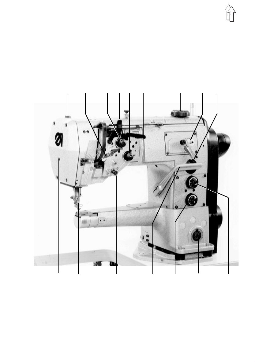
2. Operating Elements and Their Function
2.1 Elements at the Sewing Head
Element Function
1 Pressure foot screw - This screw is screwed in completely at the factory
2 Thread regulator - Setting the correct thread quantity for different
3 Control knob - Setting auxiliary tension for the needle thread.
4 Lever - Opening the main needle thread tension and
5 Control knob - Setting the main tension for the needle thread
6 Lever - Switching the auxiliary tension on and off.
7 Adjustment wheel - Setting the pressure foot stroke.
8 Lever - Bobbin thread winding device
9 Viewing glass with - Show the oil level in the reservoir.
11 fill opening The oil level must be kept above "MIN".
10 Control knob - Setting the stitch length for sewing forwards.
12 Control knob - Setting the stitch length for sewing in reverse.
13 Hand le ver - Continuous ad j ustment of the s titch length between
14 Lever - Determining the status of the main needle thread
15 Needle
and the position may not be changed.
material thicknesses, sewing yarns and stitch lengths.
auxiliary needle thread tension.
Pull the lever to the right before switching over in order to free it from its catch.
If necessary fill Esso "SP NK 10" up to the "MAX"
marking in the reservoir.
the set forward and revers e stitch length s.
tension during pressure foot lift.
Lever up: Tension open.
Lever down: Tension closed.
Caution!
Be sure to turn off the main switch when threading or
replacing the needle.
Risk of Injury.
16 Knob - Arresting the pressure foot in the raised position.
6
Page 5
12
3
56 7
4
9
8
1213141516
11
10
7
Page 6

2.2 Elements on the Frame
Element Function
Frame Type MG 55-3
1 Main switch - Switching the machine on and off
2 Pedal
Rest position - No function
Position forward - Sewing with desired rpm
Position "hal f back" - Raise pressure foot when machine at rest
Position "fu l l back" - Thread trimming and raise pressure foot
3 Screw - Setting the Table Top Height.
Frame Type MG 56-2
4 Main switch - Switching the machine on and off
5 Pedal
Rest position - No function
Position forward - Sewing with desired rpm
Position "hal f back" - Raise pressure foot when machine at rest
Position "fu l l back" - Thread trimming and raise pressure foot
6 Lever - Securing th e raised table top half
7 Brace - For supporting the lowered t able top in the
horizontal position.
8
Page 7

76 5 4
MG 55-3
123
MG 56-2
9
Page 8

Maintenance Unit
8 Air filter and - Bef ore the water level reaches th e filter, screw in
water trap screw 7 far enough to drain water.
9 Pressure regul ator - To set to 6 bar pu l l t he bushing 10 up and turn appropri ately.
not
interrupt t he compressed ai r supply.
Do
89
10
Page 9

3. Operating the S ewing Ma chine
3.1 Threading the Needle Thread.
Caution Risk of Injury !
Turn off the main switch before threading.
–
Thread the needle thread as shown in the illustration.
11
Page 10

3.2 Winding the Bobbin Thread
–
Place the bobbin 4 on the bobbin winder 3.
–
Pull the thread through the guide 1 and the tension 2.
–
Wind the thre ad approx. 5 x clock wise around the
bobbin core a nd tear off at th e t hread clamp 6.
–
Press the bobbinr lever 5 into the bobbin.
–
Sewing
The bobbin wind er lever stops the procedure when
the bobbin is full.
1
2
3
4
5
6
12
Attention !
If the thread is not to be wound during sewing, the
pressure foot must be arrested in the raised position and
the pressur e f oot stroke set at the smallest value.
Page 11

3.3 Changing the Bobbin
3
7
6
1
2
Caution Risk of Injury!
Turn off the main switch before changing the bobbin.
–
Bring the needle into the hi ghest position
–
Pull the covering cap 1 from the free-arm.
–
Remove the bobbin housing 2 with bobbin 3. Hereby
raise the bobbin case flap 4 as far as possible.
–
Remove the bobbin
–
Insert a full bobbin in such a way that, when the
thread is pulled off, it turns in the direction shown in
the illustration.
–
Pull the thread through the slit 7, under the spring 6
to the hole 5.
–
Insert the bobbin case with bobbin as far as possible
into the bobbin case base and release the bobbin
case flap.
For security press in the bobbin case with your index
finger and make sure that the bobbin case flap has
caught.
–
Push on the covering cap 1.
4
5
13
Page 12

3.4 Setting the Bobbin Thread Tension
2
1
Caution Risk of Injury!
Turn off main switch.
–
Bring the needle into the highest position
–
Pull the covering cap from the free-arm
–
Remove the bobbin housing with bobbin. Hereby
raise the bobbin case flap as far as possible.
–
Carefully turn the regulating screw 1.
To the right = Increase thread tension
To the left = Decrease thread tension
14
The initial setting for the tension spring 2 is:
The bobbin housi ng must slowly lower through its
own weight. ( see sketch)
–
Insert the bobbinn case with bobbin as far as
possible into the bobbin case base and release the
bobbin case flap. For security press in the bobbin
case with yo ur index finger and make sure that the
bobbin case fl ap has caught.
Page 13

3.5 Setting the Thread Regulator .
1
With the thread regulator the needle thread quantity
necessary fo r stitch formati on can be regul ated.
The setting is dependent on the stitch length, material
thickness an d the yarn characteristics.
Only a precisely set thread regulator assures an optimal
sewing resu l t.
The needle thread loop should glide over the hook
without excess with little tension.
In the "0" setting the greatest thread quantity is released,
such as is requi red by particularly great stit ch length and
very thick material.
Adjustment:
–
Loosen screw 1 .
–
Change the position of the thread regulator
appropriately.
–
Retighten screw 1.
Note
With a correct setting the thread check spring is pulled
approx. 1 mm down from its upper end position when the
needle thread loop passes the maximum hook
circumference.
The 1 mm dimension is a guideline. Depending on the
thread check spring tension it can be greater or smaller.
15
Page 14

4. Operating the Frame
4.1 Folding Down the Table Top (only F rame MG 56-2)
16
3
1/ 2
Caution Risk of Injury!
Hold the table top with both hands when pulling down.
–
Release the table top fasten ers 1 and 2 under the
table top and f astener 3 on the left frame leg.
–
Pull down the table top with both hands as shown in
the illustration.
–
Lock the diagonal brace 4 into t he mounting.
–
Fold up the table top in the reverse order.
4
Page 15

5. Maintenance
Caution Risk of Injury!
Turn off main switch.
Maintenance work must be co nducted at the latest after
the number o f operating hours listed in the column "
Interval". Shorter maintenance intervals may be required
when working with very linty materials.
Procedure Interval Remarks
Head
Removal of lint 8 Particularly in following areas:
accumulations Underside of t he stitch bed
Check the oil level in both
reservoirs 40 see subject 2.1
Maintenance Unit
Clean insert in the 9
air filter (page 10) 500
Transporter stays
Area around the hook
Bobbin housing top
Element 9 and 11
Caution!
Interrupt the compressed air supply
and vent the system.
17
 Loading...