

Adler 867 Service Manual

867
Spezialnähmaschine
Serviceanleitung
Service instructions
D
GB
Postfach 17 03 51, D-33703 Bielefeld • Potsdamer Straße 190, D-33719 Bielefeld
Telefon +49 (0) 5 21/ 9 25 - 00 • Telefax +49 (0) 5 21/ 9 25 24 35 • www.duerkopp-adler.com
Ausg./Edition: 01/2006 Printed in Federal Republic of Germany Teile-Nr./Part-No.: 0791 867641

General safety instructions
The non-observance of the following safety instructions can cause
bodily injuries or damages to the machine.
1. The machine must only be commissioned in full knowledge of the
2. Before putting into service also read the safety rules and
3. The machine must be used only for the purpose intended. Use of
4. When gauge parts are exchanged (e.g. needle, presser foot,
instruction book and operated by persons with appropriate
training.
instructions of the motor supplier.
the machine without the safety devices is not permitted. Observe
all the relevant safety regulations.
needle plate, feed dog and bobbin) when threading, when the
workplace is left, and during service work, the machine must be
disconnected from the mains by switching off the master switch or
disconnecting the mains plug.
5. Daily servicing work must be carried out only by appropriately
trained persons.
6. Repairs, conversion and special maintenance work must only be
carried out by technicians or persons with appropriate training.
7. For service or repair work on pneumatic systems, disconnect the
machine from the compressed air supply system (max. 7-10 bar).
Before disconnecting, reduce the pressure of the maintenance
unit.
Exceptions to this are only adjustments and functions checks
made by appropriately trained technicians.
8. Work on the electrical equipment must be carried out only by
electricians or appropriately trained persons.
9. Work on parts and systems under electric current is not permitted,
except as specified in regulations DIN VDE 0105.
10. Conversion or changes to the machine must be authorized by us
and made only in adherence to all safety regulations.
11. For repairs, only replacement parts approved by us must be used.
12. Commissioning of the sewing head is prohibited until such time
as the entire sewing unit is found to comply with EC directives.

Index Page:
Service instructions class 867
1. General notes
1.1 Gauges ..................................................... 3
1.2 Descriptionofthelockingpositions.................................... 4
1.3 Graduation on the handwheel ....................................... 5
2. Sewing machine
2.1 Positionofthearmshaftcrankonthearmshaft............................ 6
2.2 Upper and lower toothed belt wheel / toothed belt ........................... 7
2.2.1 Position of the upper toothed belt wheel ................................. 7
2.2.2 Position of the lower toothed belt wheel ................................. 8
2.3 Bottom feed and stitch regulator gear................................... 9
2.3.1 Basicsettingofstitchadjustment..................................... 9
2.3.2 Adjust the 2nd stitch length ......................................... 11
2.3.3 Positionofthefeeddoginthethroatplatecutout ........................... 12
2.3.4 Feeding motion of the feed dog ...................................... 14
2.3.5 Liftingmotionofthefeeddog........................................ 15
2.3.6 Feeddogheight ............................................... 16
2.3.7 Balanceweight................................................ 17
2.4 Transmissionlever.............................................. 18
2.5 Needle bar linkage .............................................. 19
2.5.1 Align the needle bar linkage laterally ................................... 19
2.5.2 Needle penetration in feeding direction ................................. 20
2.6 Hook, looping stroke and needle bar height ............................... 21
2.6.1 Looping stroke ................................................ 21
2.6.2 Needle bar height............................................... 22
2.6.3 Distance between hook and needle .................................... 23
2.6.4 Needle guard ................................................. 24
2.7 Bobbin case opening............................................. 25
2.7.1 General ..................................................... 25
2.7.2 Setting of the bobbin case opening .................................... 25
2.7.3 Timing of opening............................................... 27
2.8 Feeding foot and fabric presser foot ................................... 28
2.8.1 Feeding foot and presser foot stroke ................................... 28
2.8.2 Stroke motion of the feeding foot ..................................... 29
2.8.3 Sewingfootpressure ............................................ 30
2.9 Stitch length limitation ............................................ 31
2.10 Stitch equality of the forward and backward stitch ........................... 32
2.11 Sewingfootlifting............................................... 33
2.11.1 Mechanical sewing foot lift ......................................... 33
2.11.2 Height of the sewing feet arrested with hand lever ........................... 34
2.11.3Heightoftheliftedsewingfeet....................................... 35
2.12 Thread-guiding parts............................................. 36
2.12.1 Thread regulator ............................................... 36
GB

Index Page:
2.12.2Threadtake-upspring............................................ 37
2.13 Bobbin winder ................................................. 38
2.14 Threadtrimmer................................................ 40
2.14.1 General ..................................................... 40
2.14.2Threadpullingknife ............................................. 41
2.14.3 Counter-knife and lower thread clamp .................................. 42
2.14.4 Cutting position with machines having needle repositioning ..................... 44
2.14.5 Cutting position with machines without needle repositioning .................... 45
2.15 Potentiometerinthearm .......................................... 46
2.15.1 Basic setting without control panel .................................... 46
2.15.2 Basic setting with the c ontrol panel V810 or V820 ........................... 47
2.15.3Checkthepotentiometeradjustment................................... 48
2.16 Oillubrication................................................. 49
2.16.1Hooklubrication ............................................... 50
2.17 Maintenance.................................................. 51
1. General notes
The present service instructions describes the adjustment of the
special sewing machine 867.
ATTENTION !
The operations described in the service instructions must only be
executed by qualified staff or correspondingly instructed persons
respectively!
Caution: Danger of injury !
In case of repair, alteration or maintenance work turn off the main
switch and disconnect the machine from the pneumatic supply system.
Carry out adjusting operations and functional tests of the running
machine only under observation of all safety measures and with
utmost caution.
The present service instructions describes the adjustment of the
sewing machine in an appropriate sequence. Please observe in this
connection that various setting positions are interdependent.
Therefore it is absolutely necessary to do the adjustment following the
described order.
For all setting operations of parts involved in the stitch formation a new
needle without damage has to be inserted.
Machine covers having to be screwed off and on again for checking
and adjusting operations are not mentioned in the text.
GB
1.1 Gauges
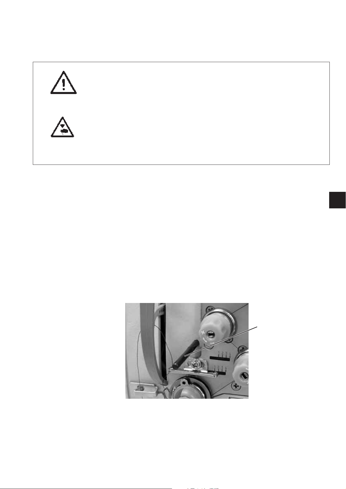
Hint:
Some of the shafts of the special sewing machine 867 are provided
with flat spots. This facilitates the adjustment considerably.
In case of all adjustments on flat spots the first screw in rotation
direction is put on such a flat spot.
1
The locking pin 1 required for adjusting the machine belongs to the
serial equipment of the machine. It is in the accessories and can be put
at the bottom side of the oil pan.
3
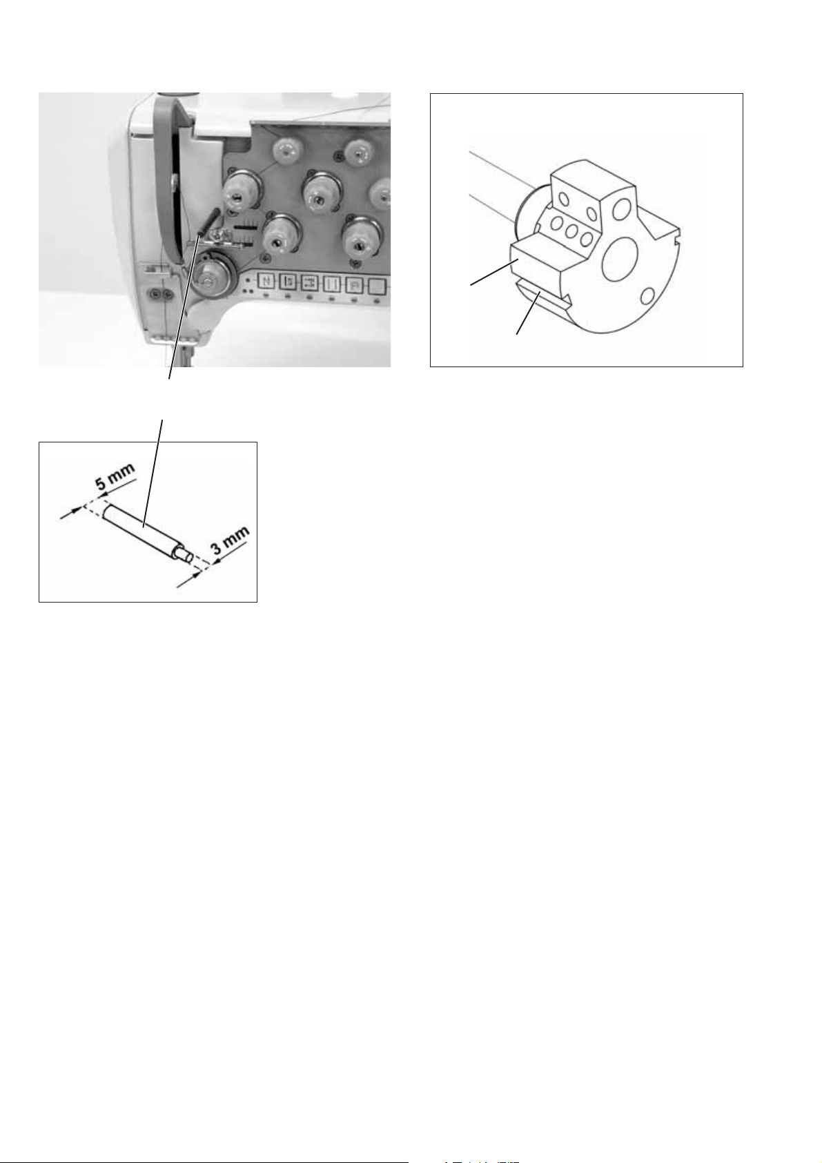
1.2 Description of the locking positions
1
With the locking pin 1 and the arresting grooves 2 and 3 in the arm
shaft crank 4 the sewing machine can be arrested in two adjusting
positions.
Position I = Locking pin Ø 5 mm for large groove
Position II = Locking pin Ø 3 mm for small groove
4
2
= Looping stroke, needle bar height
= Needle bar at its upper dead center, Graduation on
the handwheel
4

1.3 Graduation on the handwheel
The handwheel 2 has graduation printed on it.
Certain settings shall be done following to the position of the
handwheel.
–
Turn the handwheel until the degree mark mentioned in this manual
points to the index 3.
–
Carry out the described adjustment.
1
2
3
GB
Setting the Handwheel
–
Arrest the machine in position II by using the locking pin Ø 3 mm.
–
Loosen the fastening screw for the handwheel through opening 1.
–
Turn the handwheel so that the degree mark “0" points to the
index 3.
–
Tighten the fastening screw again.
–
Set the handwheel to 50° and tighten the second fastening screw.
5
2. Sewing machine
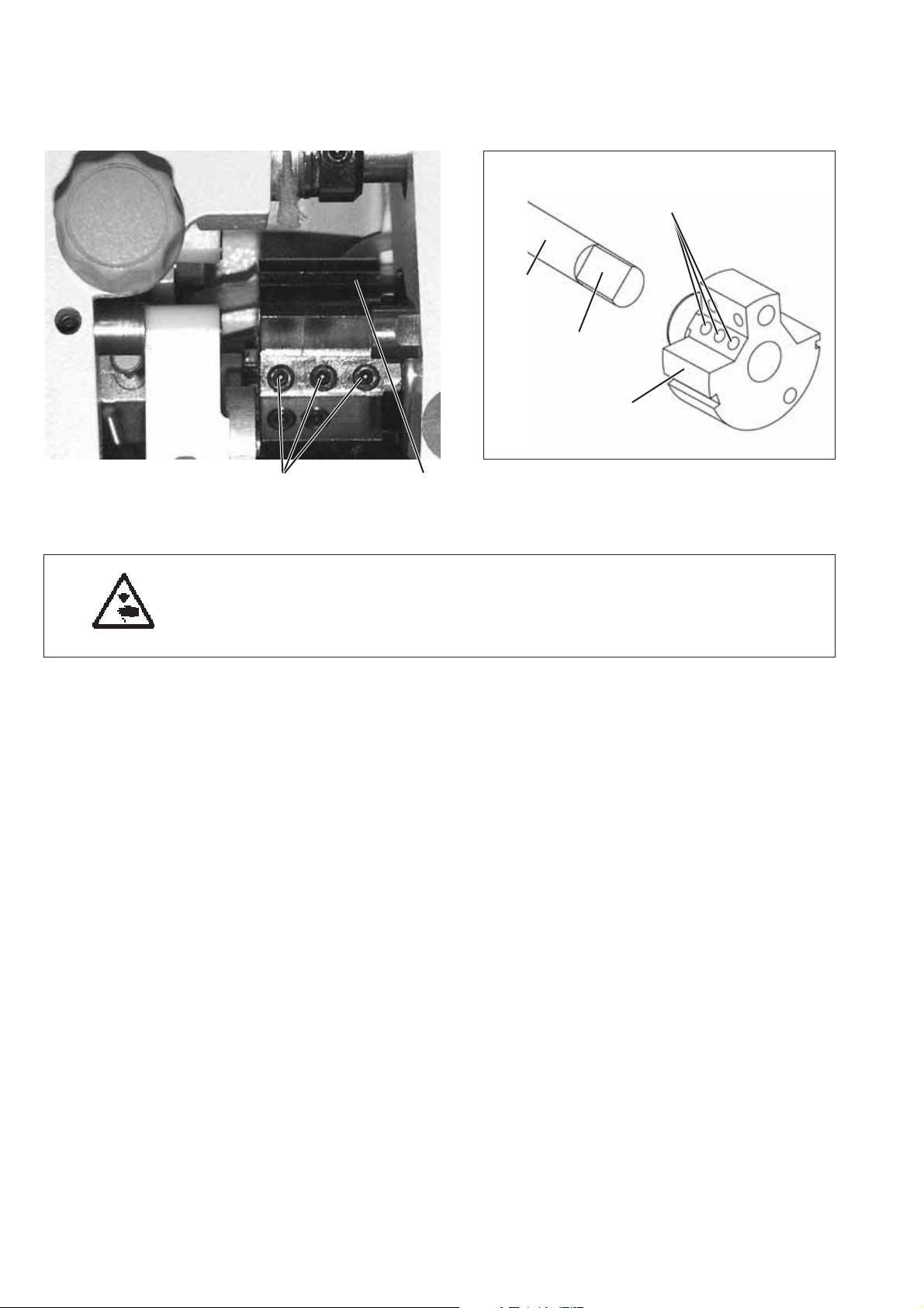
2.1 Position of the arm shaft crank on the arm shaft
21
2
4
3
1
Caution: Danger of injury !
Turnthemainswitchoff!
Check and set the position of the arm shaft crank only when the
machine is switched off.
Standard checking
The arm shaft crank 1 is fastened on the arm shaft 4 with the three
screws 2. The screws must sit on the flat spot 3.
Correction
–
Loosen screws 2 at the arm shaft crank.
–
Twist arm shaft crank 1 on the shaft in such a way that
the screws 2 sit on the flat spot 3.
–
Push arm shaft crank 1 axially to the right as far as it will go.
–
Tighten screws 2.
6
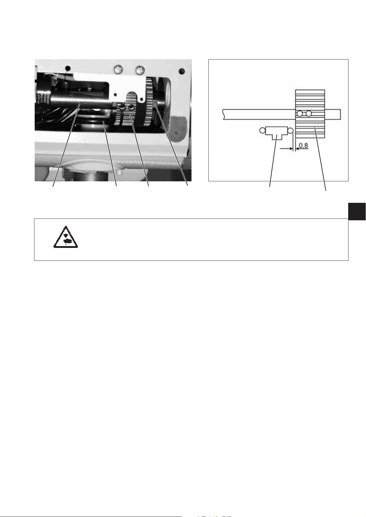
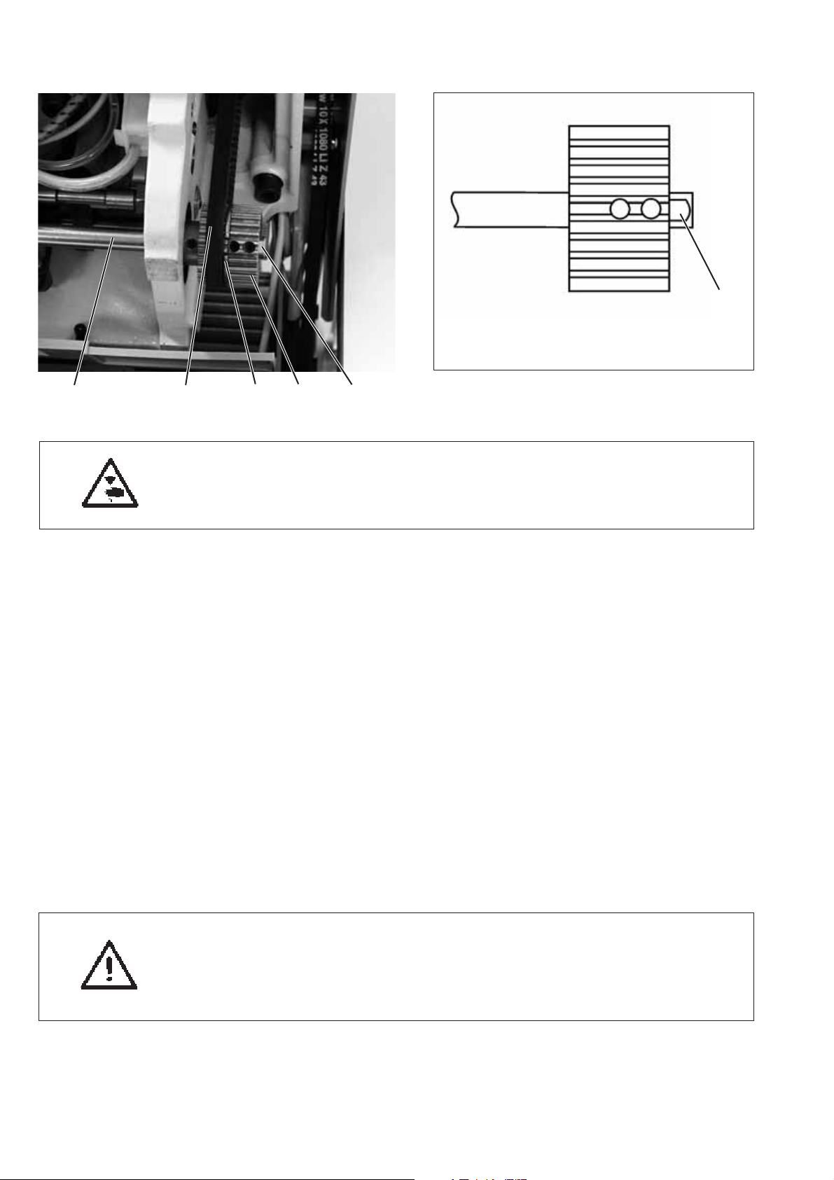
2.2 Upper and lower toothed belt wheel / toothed belt
2.2.1 Position of the upper toothed belt wheel
4321
Caution: Danger of injury !
Turnthemainswitchoff!
Check and set the position of the upper toothed belt wheel only with
the sewing machine switched off.
Standard checking
The toothed belt wheel 2 is fastened on the arm shaft 4 with two
screws. The screws must sit on the flat spot 1.
The distance between the toothed belt wheel 2 and the bobbin winder
wheel 3 must amount to 0.8 mm when the bobbin winder is switched
off.
–
Check distance between toothed belt wheel 2 and bobbin winder
wheel 3 by means of a thickness gauge.
Correction
–
Loosen the threaded pin in the toothed belt wheel.
–
Turn the toothed belt wheel, until the screws sit on the flat spot 1
of the arm shaft 4.
–
Set lateral distance of 0.8 mm between toothed belt wheel 2 and
bobbin winder wheel 3 using the thickness gauge.
–
Tighten the threaded pin in the toothed belt wheel.
32
GB
7
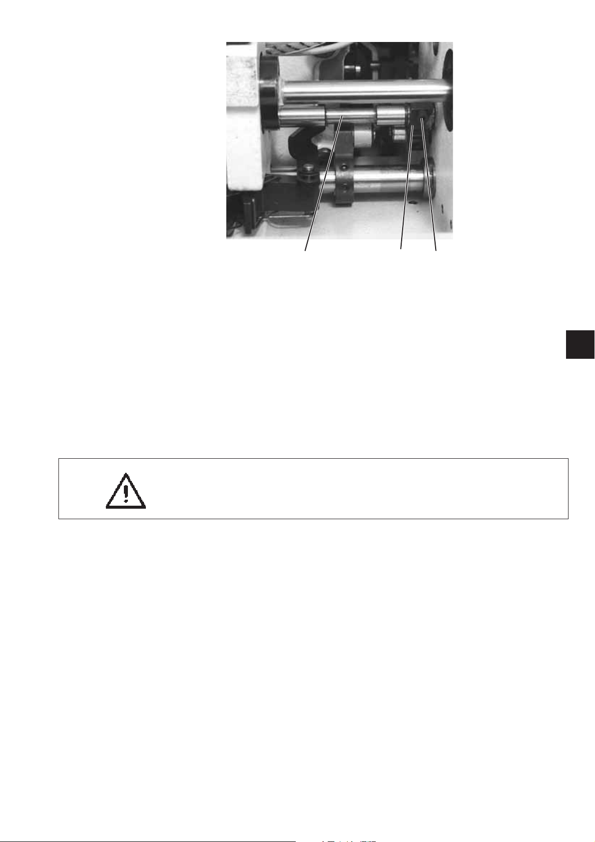
2.2.2 Position of the lower toothed belt wheel
54321
Caution: Danger of injury !
Turnthemainswitchoff!
Check and set the position of the lower toothed belt wheel
only with the sewing machine switched off.
1
Standard checking
The screws in the toothed belt wheel 2 must sit on the flat spot 1 of the
lower shaft 5.
The toothed belt wheel must be positioned in a way that the toothed
belt 4 bears against the belt tensioner ring 3 without being dislocated.
–
Check the position of the toothed belt wheel.
Correction
–
Pull out the toothed belt from the lower toothed belt wheel.
–
Loosen the threaded pin in the toothed belt wheel.
–
Turn the toothed belt wheel 1, until the screws sit on the flat spot of
the lower shaft 5.
–
Tighten the threaded pin in the toothed belt wheel 1.
–
Put the toothed belt on the toothed belt wheel again.
–
Check the course of the toothed belt.
ATTENTION Danger of breakage !
After replacing the toothed belt, check the following:
Hook adjustment (see chapter 2.6), feeding motion of the
feed dog (see chapter 2.3.4) and lifting motion of the feed dog
(see chapter 2.3.4).
8
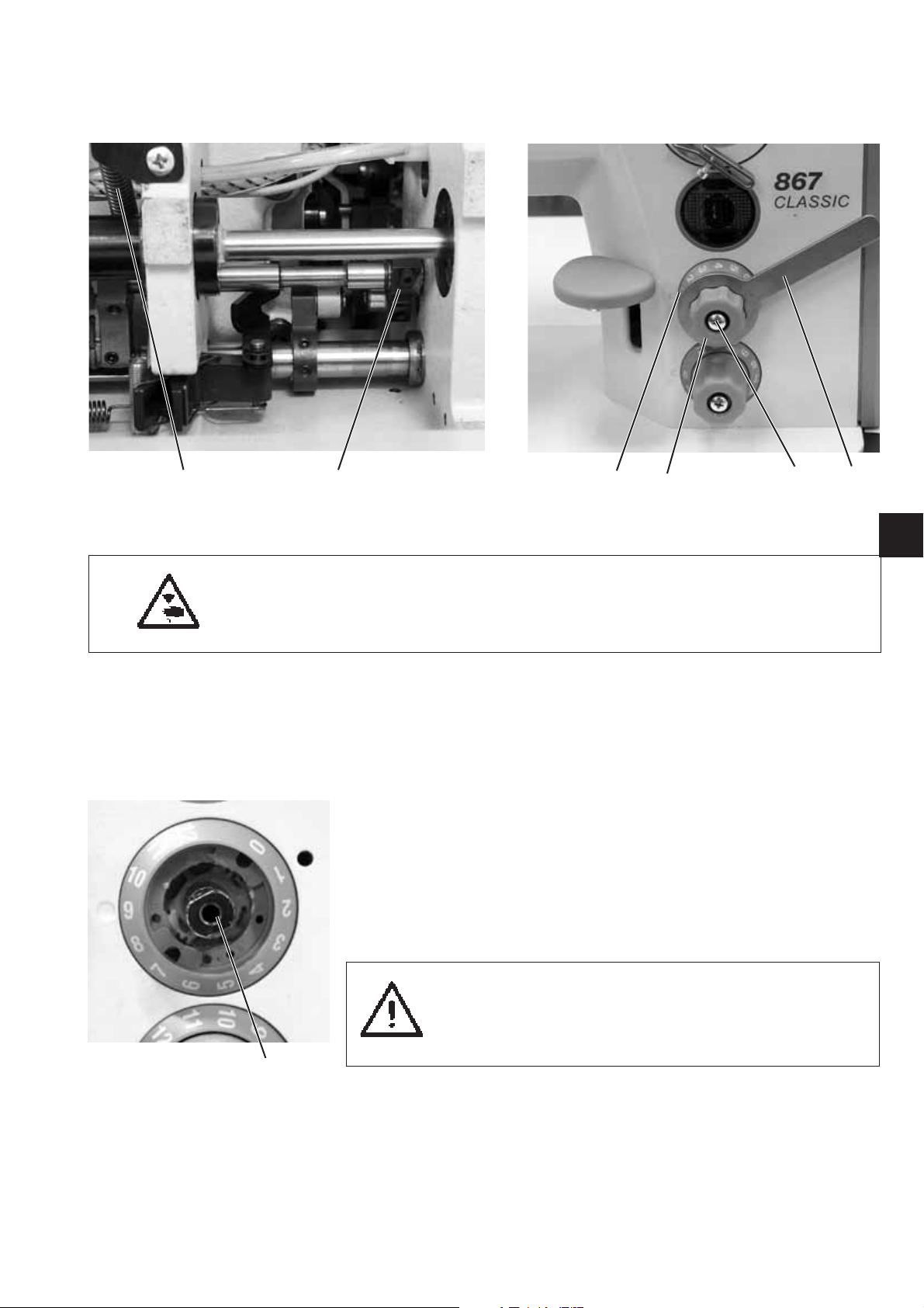
2.3 Bottom feed and stitch regulator gear
2.3.1 Basic setting of stitch adjustment
21
Caution: Danger of injury !
Turnthemainswitchoff!
Set the basic setting of stitch adjustment only with the sewing
machine switched off.
Standard checking
When the setting wheel 5 is in zero position, the stitch regulator gear
should have the least clearance possible .
–
Set stitch length “0” at the setting wheel 5.
–
Check the clearance of the stitch regulator gear at the stitch
regulator lever 1.
Correction
–
Unhook the spring 2.
–
Retain the setting wheel 5 using the wrench 3.
–
Unscrew the screw 4 and remove the setting wheel 5.
–
Turn shaft 7 to the right using a 10 mm wrench until the stitch
regulator lever 1 has the least possible clearance.
65 4 3
GB
ATTENTION: Danger of breakage !
Do not turn the shaft too far to the right .
The stitch regulator parts may jam and the
maximum stitch length of 8 mm and 6 mm
can respectively no longer be achieved.
7
–
Setscale6to“0”.
–
Put setting wheel 5 on again and tighten it with screw 4.
–
Put the spring 2 again.
–
Check the clearance of the stitch regulator lever 1.
9
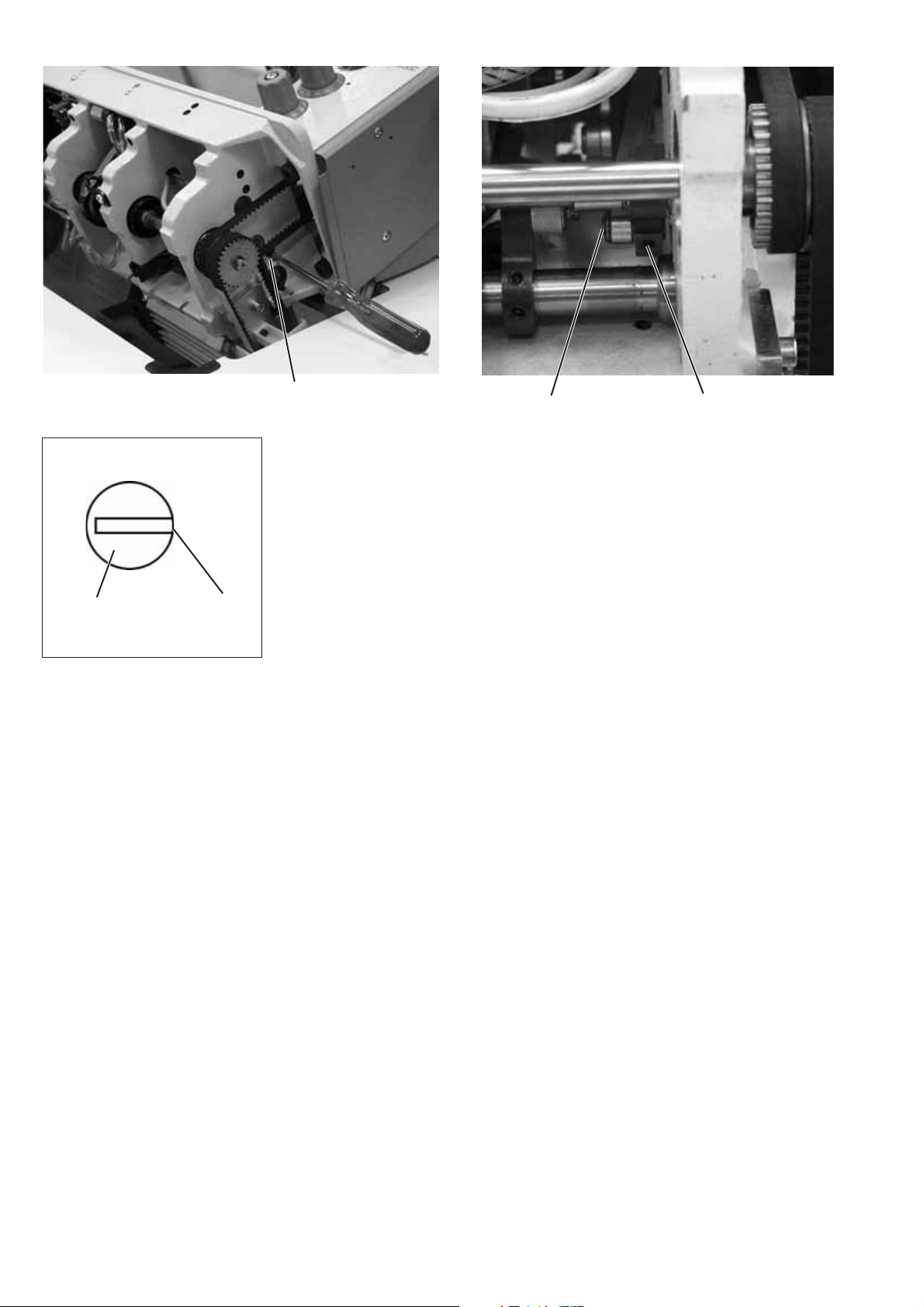
1
Adjust eccentric
The eccentric 3 has to be adjusted in such a way that the open side 4
of the eccentric slot superimposes the screw 2.
–
Loosen screw 2.
–
Through the hole 1, turn the eccentric 3 in such a way that the
open side 4 of the eccentric slot be oriented to the screw 2.
3
4
–
Tighten the screw 2.
32
10
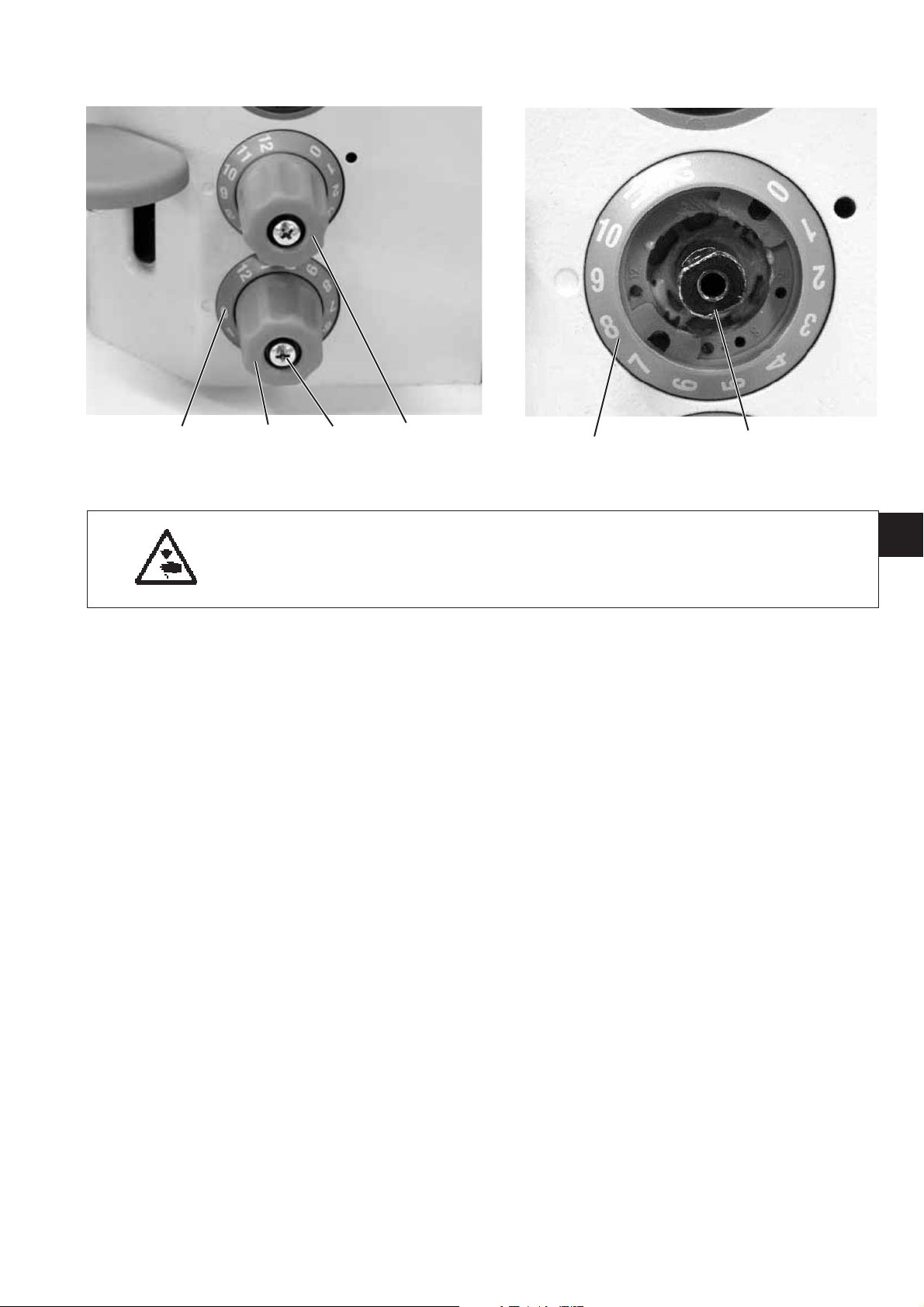
2.3.2 Adjust the 2nd stitch length
4321
Caution: Danger of injury !
Turnthemainswitchoff!
Set the basic stitch adjustment only with the sewing
machine switched off.
–
Set the upper setting wheel 1 to “4”.
–
Loosen the screw 2 and remove the setting wheel 3.
–
Using a 10 mm wrench, turn with caution the shaft 5 clockwise as
far as it will go.
–
Setscale4to“4”.
–
Put setting wheel 3 on again and tighten it with screw 2.
45
GB
11

2.3.3 Position of the feed dog in the throat plate cutout
1
2
14
98
10 11
76543
Caution: Danger of injury !
Turnthemainswitchoff!
Set and check the feed dog and the stitch adjustment gear only
with the sewing machine switched off.
–
Unhook the spring 1.
–
Loosen the screws on the adjustment rings 8 and 9.
–
Loosen screw 5.
–
Align the feed dog in the center of the throat plate cutout.
–
Arrest the shaft 7 with the adjustment rings 8 and 9 and tighten the
screws.
–
Loosen screw 10 and screw 2.
–
Loosen the screws an the thrust eccentric 4.
–
Align the positioning frame sides to sit in the center between the
cutouts on the shaft 7.
–
Arrest the positioning frame axially with the bearing bolt 6 (fixed
with screw 10) and the adjustment ring 2.
–
Tighten the screws on the thrust eccentric 4.
12
Note: The shaft 11 is fixed on surface in the positioning frame 14
at position 3 with two screws in series.
11 12 13
–
Turn the stitch regulator handwheel to position “0".
–
Set the gear to “0".
In order to do so turn the positioning frame14 so that the tongues
come parallel to each other
–
Tighten the screw 13 on the block 12.
–
Align the feed dog in longitudinal direction in the center of the
throat plate cutout.
–
Tighten the screw 5 (see picture on page 12).
–
Fit in the spring 1 (see picture on page 12) on the positioning frame
and the fastening bracket.
ATTENTION: Danger of breakage !
The shaft 11 must not reach so far into the positioning frame 14
that the tongues are hindered in their movements.
GB
13

2.3.4 Feeding motion of the feed dog
21
Caution: Danger of injury !
Turnthemainswitchoff!
Adjust the feeding motion of the feed dog only with the sewing
machine switched off.
Standard checking
When the machine is in position “190°” the feed dog must not
move upon actuating the stitch regulator lever if the maximum
stitch length is set.
–
Set the maximum stitch length.
–
Turn the machine to position “190°”.
–
Move the stitch regulator lever and check whether the feed dog
stands still.
Correction
–
Loosen the screws on the thrust eccentric 1.
–
Adjust thrust eccentric 1.
–
Tighten the screws on the thrust eccentric 1.
–
Move the stitch regulator lever and check whether the feed dog
stands still.
14

2.3.5 Lifting motion of the feed dog
Caution: Danger of injury !
Turnthemainswitchoff!
Adjust the lifting motion of the feed dog only with the sewing
machine switched off.
1
GB
Standard checking
The feed dog is supposed to have the same distance to the throat plate
at its front and backward dead center:
–
Turn the handwheel and check the movement of the feed dog.
Correction
–
Loosen the screws on the lifting cam 1.
–
Turn the lifting cam.
–
Tighten the screws on the lifting cam 1.
–
Check the setting.
15
 Loading...