

Adler 806 Installation Instruction

Contents Page:
Home
Part 2: Installation instructions class 806
1. Items of the sewing unit delivered
2. Installing the sewing unit
2.1 Transport safety devices . . . . . . . . . . . . . . . . . . . . . . . . . . . . . . . . . . . . . . . 4
2.2 Balancing the sewing unit . . . . . . . . . . . . . . . . . . . . . . . . . . . . . . . . . . . . . . . 5
2.3 Assembling the reel stand . . . . . . . . . . . . . . . . . . . . . . . . . . . . . . . . . . . . . . . 5
2.4 Assembling the stacker plate . . . . . . . . . . . . . . . . . . . . . . . . . . . . . . . . . . . . . 5
2.5 Assembling the DAC control unit . . . . . . . . . . . . . . . . . . . . . . . . . . . . . . . . . . . 5
3. Covers
3.1 Removing the covers above the table . . . . . . . . . . . . . . . . . . . . . . . . . . . . . . . . 7
3.2 Removing the covers below the table . . . . . . . . . . . . . . . . . . . . . . . . . . . . . . . . 7
3.3 Fitting the covers above the table . . . . . . . . . . . . . . . . . . . . . . . . . . . . . . . . . . 9
3.4 Fitting the covers below the table . . . . . . . . . . . . . . . . . . . . . . . . . . . . . . . . . . 9
4. Electrical connection
4.1 Checking the nominal voltage . . . . . . . . . . . . . . . . . . . . . . . . . . . . . . . . . . . . 10
4.2 Checking the step-motor setting . . . . . . . . . . . . . . . . . . . . . . . . . . . . . . . . . . . 10
5. Pneumatic connection
. . . . . . . . . . . . . . . . . . . . . . . . . . . . . . . . . . . . . . . . 11
. . . . . . . . . . . . . . . . . . . . . . . . . . . . . . . . . 3
6. Refilling the oil
6.1 Head no. 806-121 . . . . . . . . . . . . . . . . . . . . . . . . . . . . . . . . . . . . . . . . . . . 12
6.2 Head no. 806-111 . . . . . . . . . . . . . . . . . . . . . . . . . . . . . . . . . . . . . . . . . . . 13
6.3 Regulating the lubrication of the shuttle . . . . . . . . . . . . . . . . . . . . . . . . . . . . . . . 13
6.4 Lubricating wicks and felts . . . . . . . . . . . . . . . . . . . . . . . . . . . . . . . . . . . . . . 14
7. Initial operation
7.1 Checking the machine adjustment . . . . . . . . . . . . . . . . . . . . . . . . . . . . . . . . . . 15
7.2 Selecting the machine class . . . . . . . . . . . . . . . . . . . . . . . . . . . . . . . . . . . . . 15
7.3 Residual thread monitor (only 806-121) . . . . . . . . . . . . . . . . . . . . . . . . . . . . . . . 15
7.4 Transfer plate . . . . . . . . . . . . . . . . . . . . . . . . . . . . . . . . . . . . . . . . . . . . . . 16
7.4.1 Setting reference point . . . . . . . . . . . . . . . . . . . . . . . . . . . . . . . . . . . . . . . . 16
7.4.2 Position balancing . . . . . . . . . . . . . . . . . . . . . . . . . . . . . . . . . . . . . . . . . . . 17
7.4.3 Carrying out the position balancing . . . . . . . . . . . . . . . . . . . . . . . . . . . . . . . . . 18
7.5 Test run . . . . . . . . . . . . . . . . . . . . . . . . . . . . . . . . . . . . . . . . . . . . . . . . . 20
1. Items of the sewing unit delivered
The items delivered depend on your order. Before installing the unit
please check whether all parts required have been received.
–
Basic equi p me nt pr o vi de d with sewing he ad no . 2 71 for light
sewing mate ri al o r s ewing head no. 467 fo r me di u m t o h ea v y
sewing material depending on the subclass.
–
Additional e qu i pm en t
–
Supplementary hardware
3

2. Installing the sewing unit
CAUTION
The sewing unit may only be installed by skilled personnel.
1
2
3
2.1 Transport safety devices
The followi ng un i ts a re s e c ur e d b y means of transpor t s af et y de v i ces :
–
Sewing head
–
Stacker
–
Transfer carriage
–
Folding device
Removing the transport safety devices
–
Remove the cove r s ab ov e th e t ab l e a cc ord i ng to s ect i on 3. 1.
–
Loosen the screws 2 of the transport safety device on the sewing
head.
–
Remove the transport safety device 3.
–
Remove the hol din g s t r aps on th e s t ack e r.
–
Tilt the stacker forward.
–
Remove the hol din g s t r aps on th e t r an sfe r car ri a ge .
–
Remove the ho l din g s t r ap s on th e c yl i n de r 1 o f t he fo l di n g d ev i ce .
–
Remove the wood en bl o ck on th e c yl i n de r 1.
–
Mount the cove r s ab ov e th e t ab l e a c cor d i ng to s ection 3.3.
4

2.2 Balancing the sewi ng unit
4 5
The four feet 6 serve to centre the sewing unit. Make sure that the
weight is even l y di s t ri bu te d o n t he fo ur feet.
–
–
–
–
1
2
3
Place a lev e l on th e stand.
Loosen the locknut 7.
Alter the height by turning the foot 6.
Tighten the locknut 7.
6 7
2.3 A ssembli ng the ree l stand
–
Insert the reel stand 1 in the bore hole of the reel-stand carrier 3.
–
Clamp the reel stand with the clamping lever 2 so that the thread
guide runs in parallel to the head of the sewing machine.
2.4 A ssembli ng the stac ker plat e
–
Clamp the s ta c ker p l at es f or the pocket cut s on th e supporting
barÿ4 using tw o f i x ing screws.
–
Align the s ta c k er p l at es f or t he s ew i ng ma te r i al.
2.5 Assembling the DAC control unit
–
Put the DAC control unit into the bore hole 5 of the folding station
cover.
–
Fix the DAC control unit using the fixing screw.
–
Insert the plug into the back of the DAC control unit.
5
5
1
6
7
2
8
3
4
9
10
11
6

3. Covers
3.1 Removi ng the covers above the table
Make absolutely sure to remove the covers above the table in the
order descri b ed be l ow.
Cover 6 sewing head
–
Loosen the cl a mp i ng on th e r e el s t an d.
–
Pull the re el stand up and out.
–
Move the cover to the right and lift it off.
Cover 5 carriage
–
Remove the cover by lifting it off.
Cover 1 folding station
–
Loosen the fixture of the control.
–
Pull the control up and remove it.
–
Pull the cover up and remove it.
At the same t i me pa y attention to the c o nt r ol -p anel guide.
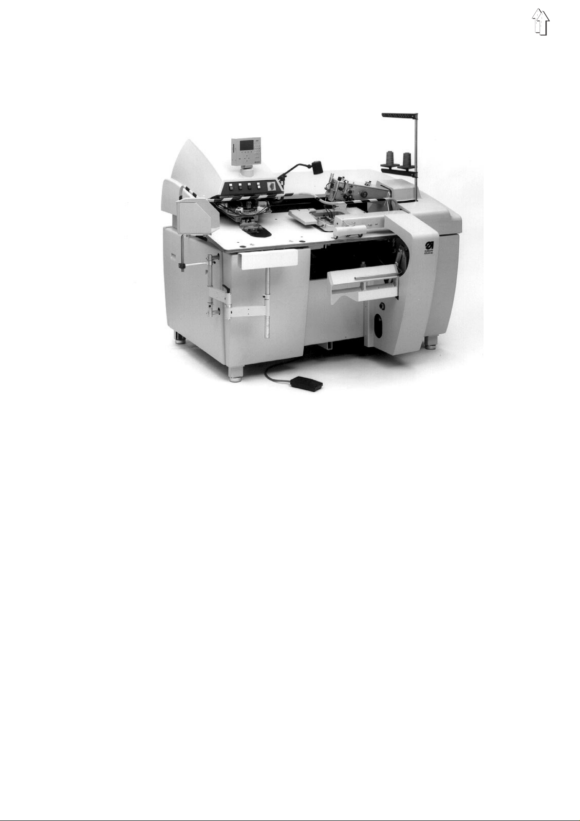
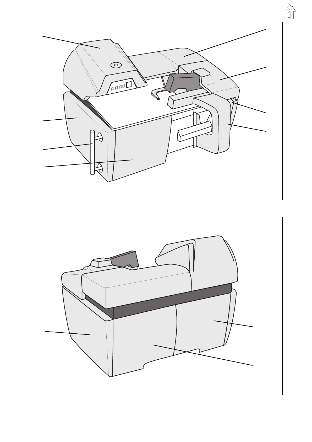
3.2 Removi ng the covers below the table
Cover 10 on the left at the back and cover 11 on the right at the
back
–
Pull the covers up and remove them towards the front.
Covers 4 on the left at the front and Cover 7 on the right at the
front
–
Pull the covers up and remove them towards the front.
Cover 2 left-hand side
–
Dismantle the stacker plates.
–
Pull the covers up and remove them towards the front.
Cover 9 right-hand side
–
Pull the covers up and remove them towards the front.
Cover 8 Stacker
–
Swing the stacker plate towards the machine.
–
Loosen all 7 fixing screws.
–
Pull the cover o ff tow ard s th e f ron t.
7
 Loading...