

Adler 806 Service Manual

Contents: Page:
Home
Part 3: Service Instructions class. 806
1. General
2. Machine head (Class 806-111)
2.1 Stitch regulator and transmission lever . . . . . . . . . . . . . . . . . . . . . . . . . . . . . . 6
2.1.1 0-position of the stitch regulator . . . . . . . . . . . . . . . . . . . . . . . . . . . . . . . . . . 6
2.1.2 Position of the transmission lever . . . . . . . . . . . . . . . . . . . . . . . . . . . . . . . . . 7
2.2 Rocker and throat plate . . . . . . . . . . . . . . . . . . . . . . . . . . . . . . . . . . . . . . . 9
2.2.1 General information . . . . . . . . . . . . . . . . . . . . . . . . . . . . . . . . . . . . . . . . . 9
2.2.2 Position of the rocker . . . . . . . . . . . . . . . . . . . . . . . . . . . . . . . . . . . . . . . . 9
2.2.3 Timing the rocker oscillation . . . . . . . . . . . . . . . . . . . . . . . . . . . . . . . . . . . . 10
2.2.4 Range of the rocker oscillation (throw width) . . . . . . . . . . . . . . . . . . . . . . . . . . . 11
2.2.5 Horizontal position of the throat plate . . . . . . . . . . . . . . . . . . . . . . . . . . . . . . . 12
2.2.6 Height of the throat plate . . . . . . . . . . . . . . . . . . . . . . . . . . . . . . . . . . . . . . 13
2.3 Adjusting the bobbin winder . . . . . . . . . . . . . . . . . . . . . . . . . . . . . . . . . . . . . 14
2.4 Hook, needle bar, hook guard and needle guide . . . . . . . . . . . . . . . . . . . . . . . . . 15
2.4.1 Loop stroke . . . . . . . . . . . . . . . . . . . . . . . . . . . . . . . . . . . . . . . . . . . . . . 15
2.4.2 Sliding clutch . . . . . . . . . . . . . . . . . . . . . . . . . . . . . . . . . . . . . . . . . . . . . 16
2.4.3 Needle bar height . . . . . . . . . . . . . . . . . . . . . . . . . . . . . . . . . . . . . . . . . . 17
2.4.4 Distance between the hook and the needle . . . . . . . . . . . . . . . . . . . . . . . . . . . . 18
2.4.5 Position of the needle guide . . . . . . . . . . . . . . . . . . . . . . . . . . . . . . . . . . . . 19
2.5 Bobbin case lifter . . . . . . . . . . . . . . . . . . . . . . . . . . . . . . . . . . . . . . . . . . 20
2.5.1 General information . . . . . . . . . . . . . . . . . . . . . . . . . . . . . . . . . . . . . . . . . 20
2.5.2 Amount of the finger travel . . . . . . . . . . . . . . . . . . . . . . . . . . . . . . . . . . . . . 20
2.5.3 Amount of the lifting gap (position of the finger travel) . . . . . . . . . . . . . . . . . . . . . . 21
2.5.4 Timing the bobbin case lifting . . . . . . . . . . . . . . . . . . . . . . . . . . . . . . . . . . . . 22
2.6 Sewing foot . . . . . . . . . . . . . . . . . . . . . . . . . . . . . . . . . . . . . . . . . . . . . . 23
2.6.1 General information . . . . . . . . . . . . . . . . . . . . . . . . . . . . . . . . . . . . . . . . . 23
2.6.2 Timing the sewing foot movement . . . . . . . . . . . . . . . . . . . . . . . . . . . . . . . . . 23
2.7 Thread take-up spring . . . . . . . . . . . . . . . . . . . . . . . . . . . . . . . . . . . . . . . . 24
2.8 Lifting the thread tensioner . . . . . . . . . . . . . . . . . . . . . . . . . . . . . . . . . . . . . 25
2.9 Thread advancing device . . . . . . . . . . . . . . . . . . . . . . . . . . . . . . . . . . . . . . 26
2.10 Lubrication . . . . . . . . . . . . . . . . . . . . . . . . . . . . . . . . . . . . . . . . . . . . . . 27
2.10.1 General information . . . . . . . . . . . . . . . . . . . . . . . . . . . . . . . . . . . . . . . . . 27
2.10.2 Mode of function . . . . . . . . . . . . . . . . . . . . . . . . . . . . . . . . . . . . . . . . . . . 28
2.10.3 Checking oil level and oil supply . . . . . . . . . . . . . . . . . . . . . . . . . . . . . . . . . . 28
2.10.4 Adjusting the hook lubrication . . . . . . . . . . . . . . . . . . . . . . . . . . . . . . . . . . . 29
2.10.5 Oil change . . . . . . . . . . . . . . . . . . . . . . . . . . . . . . . . . . . . . . . . . . . . . . 30
2.10.6 Topping-up oil . . . . . . . . . . . . . . . . . . . . . . . . . . . . . . . . . . . . . . . . . . . . 30
2.11 Sewing arm . . . . . . . . . . . . . . . . . . . . . . . . . . . . . . . . . . . . . . . . . . . . . . 31
2.11.1 General information . . . . . . . . . . . . . . . . . . . . . . . . . . . . . . . . . . . . . . . . . 31
2.11.2 Lower position of the arm . . . . . . . . . . . . . . . . . . . . . . . . . . . . . . . . . . . . . . 31
2.11.3 Speed "Sewing arm up and down " . . . . . . . . . . . . . . . . . . . . . . . . . . . . . . . . . 31
2.11.4 Damping the cylinder in its end position . . . . . . . . . . . . . . . . . . . . . . . . . . . . . . 32
. . . . . . . . . . . . . . . . . . . . . . . . . . . . . . . . . . . . . . . . . . . . . . . . 5

Contents: Page:
2.12 Thread cutter . . . . . . . . . . . . . . . . . . . . . . . . . . . . . . . . . . . . . . . . . . . . 33
2.12.1 Sequence of functions . . . . . . . . . . . . . . . . . . . . . . . . . . . . . . . . . . . . . . . 33
2.12.2 Lateral position of the thread pulling knife . . . . . . . . . . . . . . . . . . . . . . . . . . . . 34
2.12.3 Height of the thread pulling knife . . . . . . . . . . . . . . . . . . . . . . . . . . . . . . . . . 35
2.12.4 Position of the counter-knife in respect to the thread pulling knife . . . . . . . . . . . . . . . 36
2.12.5 Position of the hook thread clamp . . . . . . . . . . . . . . . . . . . . . . . . . . . . . . . . . 37
2.12.6 Position of the control cam . . . . . . . . . . . . . . . . . . . . . . . . . . . . . . . . . . . . . 38
2.12.7 Swivelling range of the thread pulling knife . . . . . . . . . . . . . . . . . . . . . . . . . . . 38
2.12.8 Position of the roller lever in respect to the control cam . . . . . . . . . . . . . . . . . . . . 39
2.12.9 1
3. Machine he ad ( C la ss 80 6- 1 21 )
3.1 Adjustment aids . . . . . . . . . . . . . . . . . . . . . . . . . . . . . . . . . . . . . . . . . . . 41
3.1.1 Gauge set . . . . . . . . . . . . . . . . . . . . . . . . . . . . . . . . . . . . . . . . . . . . . . 41
3.1.2 Description and adjustment of the integrated adjustment disk . . . . . . . . . . . . . . . . . 42
3.1.3 Position of the integrated adjustment disk in respect to the arm shaft . . . . . . . . . . . . . 43
3.2 Sewing foot height / lower stroke position . . . . . . . . . . . . . . . . . . . . . . . . . . . . 44
3.3 Needle thread tension release . . . . . . . . . . . . . . . . . . . . . . . . . . . . . . . . . . . 45
3.4 Thread tensioning spring . . . . . . . . . . . . . . . . . . . . . . . . . . . . . . . . . . . . . . 46
3.5 Bobbin winder . . . . . . . . . . . . . . . . . . . . . . . . . . . . . . . . . . . . . . . . . . . . 47
3.5.1 Adjusting the bobbin winder . . . . . . . . . . . . . . . . . . . . . . . . . . . . . . . . . . . . 47
3.5.2 Cylindrical winding . . . . . . . . . . . . . . . . . . . . . . . . . . . . . . . . . . . . . . . . . 47
3.5.3 Replacing friction ring . . . . . . . . . . . . . . . . . . . . . . . . . . . . . . . . . . . . . . . 48
3.5.4 Resetting bobbin winder wheel . . . . . . . . . . . . . . . . . . . . . . . . . . . . . . . . . . 48
3.6 Hook adjustments . . . . . . . . . . . . . . . . . . . . . . . . . . . . . . . . . . . . . . . . . . 49
3.6.1 Loop stroke and distance between the hook and the needle . . . . . . . . . . . . . . . . . . 49
3.6.2 Hook drive housing . . . . . . . . . . . . . . . . . . . . . . . . . . . . . . . . . . . . . . . . . 50
3.6.3 Bobbin case support . . . . . . . . . . . . . . . . . . . . . . . . . . . . . . . . . . . . . . . . 51
3.6.4 Adjusting the throat plate . . . . . . . . . . . . . . . . . . . . . . . . . . . . . . . . . . . . . 52
3.6.5 Adjusting the hook guard . . . . . . . . . . . . . . . . . . . . . . . . . . . . . . . . . . . . . . 53
3.7 Thread cutter . . . . . . . . . . . . . . . . . . . . . . . . . . . . . . . . . . . . . . . . . . . . 54
3.7.1 Control cam for timing the knife movement . . . . . . . . . . . . . . . . . . . . . . . . . . . . 54
3.7.2 Position of the stationary knife . . . . . . . . . . . . . . . . . . . . . . . . . . . . . . . . . . 55
3.7.3 Regrinding the stationary knife . . . . . . . . . . . . . . . . . . . . . . . . . . . . . . . . . . 56
3.7.4 Adjustment sheet . . . . . . . . . . . . . . . . . . . . . . . . . . . . . . . . . . . . . . . . . . 57
3.7.5 Hook-knife . . . . . . . . . . . . . . . . . . . . . . . . . . . . . . . . . . . . . . . . . . . . . . 58
3.7.6 Cutting pressure . . . . . . . . . . . . . . . . . . . . . . . . . . . . . . . . . . . . . . . . . . 59
3.8 Replacing right hand arm shaft bearing . . . . . . . . . . . . . . . . . . . . . . . . . . . . . . 60
3.9 Lubrication . . . . . . . . . . . . . . . . . . . . . . . . . . . . . . . . . . . . . . . . . . . . . . 61
3.9.1 General information . . . . . . . . . . . . . . . . . . . . . . . . . . . . . . . . . . . . . . . . 61
3.9.2 Checking oil level and oil supply . . . . . . . . . . . . . . . . . . . . . . . . . . . . . . . . . 62
3.9.3 Hook lubrication . . . . . . . . . . . . . . . . . . . . . . . . . . . . . . . . . . . . . . . . . . . 64
3.10 Adjusting the remaining thread monitor . . . . . . . . . . . . . . . . . . . . . . . . . . . . . . 65
3.11 Sewing arm position . . . . . . . . . . . . . . . . . . . . . . . . . . . . . . . . . . . . . . . . 66
3.11.1 Lower position of the arm . . . . . . . . . . . . . . . . . . . . . . . . . . . . . . . . . . . . . 66
3.11.2 Speed of the sewing arm . . . . . . . . . . . . . . . . . . . . . . . . . . . . . . . . . . . . . . 66
3.11.3 Damping the cylinder in its end position . . . . . . . . . . . . . . . . . . . . . . . . . . . . . 67
st
and 2nd position of the thread cutter . . . . . . . . . . . . . . . . . . . . . . . . . . . . . . 40

Contents: Page:
4. Folding device
4.1 Outer frame . . . . . . . . . . . . . . . . . . . . . . . . . . . . . . . . . . . . . . . . . . . . . . 68
4.1.1 General information . . . . . . . . . . . . . . . . . . . . . . . . . . . . . . . . . . . . . . . . . 68
4.1.2 "Folding position" of the outer frame . . . . . . . . . . . . . . . . . . . . . . . . . . . . . . . . 68
4.1.3 Timing the action of the switches . . . . . . . . . . . . . . . . . . . . . . . . . . . . . . . . . . 69
4.1.4 Damping the cylinder in its end position . . . . . . . . . . . . . . . . . . . . . . . . . . . . . . 70
4.2 Inner frame . . . . . . . . . . . . . . . . . . . . . . . . . . . . . . . . . . . . . . . . . . . . . . 71
4.2.1 General information . . . . . . . . . . . . . . . . . . . . . . . . . . . . . . . . . . . . . . . . . 71
4.2.2 Adjustment range of the front setting wheel . . . . . . . . . . . . . . . . . . . . . . . . . . . 71
4.3 Middle slide . . . . . . . . . . . . . . . . . . . . . . . . . . . . . . . . . . . . . . . . . . . . . . 72
4.3.1 General information . . . . . . . . . . . . . . . . . . . . . . . . . . . . . . . . . . . . . . . . . 72
4.3.2 Adjustment range of the rear setting wheel . . . . . . . . . . . . . . . . . . . . . . . . . . . . 73
4.3.3 Limiting the movement" Middle slide up " . . . . . . . . . . . . . . . . . . . . . . . . . . . . . 74
4.3.4 "Adjustment position" of the middle slide . . . . . . . . . . . . . . . . . . . . . . . . . . . . . 75
4.3.5 Speed "Middle slide forwards, down, up " . . . . . . . . . . . . . . . . . . . . . . . . . . . . . 76
4.3.6 Timing the operation of the switches . . . . . . . . . . . . . . . . . . . . . . . . . . . . . . . . 77
4.4 Lateral slide, front slide and corner slide . . . . . . . . . . . . . . . . . . . . . . . . . . . . . 78
4.4.1 General information . . . . . . . . . . . . . . . . . . . . . . . . . . . . . . . . . . . . . . . . . 78
4.4.2 Front position of the slide . . . . . . . . . . . . . . . . . . . . . . . . . . . . . . . . . . . . . . 78
4.5 Corner slide . . . . . . . . . . . . . . . . . . . . . . . . . . . . . . . . . . . . . . . . . . . . . 79
4.5.1 Position of the "Folding edge" of the lateral slide . . . . . . . . . . . . . . . . . . . . . . . . . 79
4.5.2 General information . . . . . . . . . . . . . . . . . . . . . . . . . . . . . . . . . . . . . . . . . 80
4.5.3 Position of the entered corner introduction slide . . . . . . . . . . . . . . . . . . . . . . . . . 80
4.5.4 Height of the corner introduction slide . . . . . . . . . . . . . . . . . . . . . . . . . . . . . . . 81
4.6 Position of the two setting wheels . . . . . . . . . . . . . . . . . . . . . . . . . . . . . . . . . 82
5. Stacker
5.1 General information . . . . . . . . . . . . . . . . . . . . . . . . . . . . . . . . . . . . . . . . . 83
5.2 Turning the rest of the stacker . . . . . . . . . . . . . . . . . . . . . . . . . . . . . . . . . . . 84
5.3 Lateral position of the roller-out and of the stacker . . . . . . . . . . . . . . . . . . . . . . . . 85
5.3.1 Lateral position of the roller-out . . . . . . . . . . . . . . . . . . . . . . . . . . . . . . . . . . 85
5.3.2 Lateral position of the stacker . . . . . . . . . . . . . . . . . . . . . . . . . . . . . . . . . . . 85
5.4 Position of the opened inner shackle . . . . . . . . . . . . . . . . . . . . . . . . . . . . . . . . 86
5.5 Position of the opened outer shackle . . . . . . . . . . . . . . . . . . . . . . . . . . . . . . . 86
5.6 Sensitivity of the light barrier . . . . . . . . . . . . . . . . . . . . . . . . . . . . . . . . . . . . 87
5.7 Lower position of the rollers of the roller-out . . . . . . . . . . . . . . . . . . . . . . . . . . . 87
5.8 Speed of the outer shackle, of the inner shackle and of the deposit rest . . . . . . . . . . . . 88
5.9 Speed of "Ejection rollers up and down " . . . . . . . . . . . . . . . . . . . . . . . . . . . . . 89
5.10 Intensity of the air current and blowing direction of the nozzle . . . . . . . . . . . . . . . . . 89
6. Adjustment options
6.1 Selecting the machine class . . . . . . . . . . . . . . . . . . . . . . . . . . . . . . . . . . . . 90
6.2 Remaining thread monitor (only 806-121) . . . . . . . . . . . . . . . . . . . . . . . . . . . . . 90
6.3 Continuous operation . . . . . . . . . . . . . . . . . . . . . . . . . . . . . . . . . . . . . . . . 91
6.4 End bearing switch of the transfer carriage available . . . . . . . . . . . . . . . . . . . . . . 91
6.5 Measuring the end positions of the transfer carriage . . . . . . . . . . . . . . . . . . . . . . . 91
6.6 Checking the roll-out . . . . . . . . . . . . . . . . . . . . . . . . . . . . . . . . . . . . . . . . . 92
6.7 Checking the sewing motor . . . . . . . . . . . . . . . . . . . . . . . . . . . . . . . . . . . . . 92

Contents: Page:
7. Transfer carriages
7.1 General information . . . . . . . . . . . . . . . . . . . . . . . . . . . . . . . . . . . . . . . . 93
7.2 Adjusting the parallelism of the transfer plate . . . . . . . . . . . . . . . . . . . . . . . . . . 93
7.3 Setting the reference point . . . . . . . . . . . . . . . . . . . . . . . . . . . . . . . . . . . . . 94
7.4 Setting the limit switches S45 and S59 . . . . . . . . . . . . . . . . . . . . . . . . . . . . . . 95
7.4.1 X-axis . . . . . . . . . . . . . . . . . . . . . . . . . . . . . . . . . . . . . . . . . . . . . . . . 95
7.4.2 Y-axis . . . . . . . . . . . . . . . . . . . . . . . . . . . . . . . . . . . . . . . . . . . . . . . . 96
7.5 Position balance . . . . . . . . . . . . . . . . . . . . . . . . . . . . . . . . . . . . . . . . . . 97
7.5.1 General . . . . . . . . . . . . . . . . . . . . . . . . . . . . . . . . . . . . . . . . . . . . . . . 97
7.5.2 Balancing the positions . . . . . . . . . . . . . . . . . . . . . . . . . . . . . . . . . . . . . . . 98
8. Multitest System
8.1 Displaying the programme version and the check sum . . . . . . . . . . . . . . . . . . . . . 100
8.2 Testing the working memory . . . . . . . . . . . . . . . . . . . . . . . . . . . . . . . . . . . . 101
8.3 Displaying the DIP switch setting . . . . . . . . . . . . . . . . . . . . . . . . . . . . . . . . . 101
8.4 Selecting input elements . . . . . . . . . . . . . . . . . . . . . . . . . . . . . . . . . . . . . . 101
8.5 Checking input elements . . . . . . . . . . . . . . . . . . . . . . . . . . . . . . . . . . . . . . 102
8.6 Selecting output elements . . . . . . . . . . . . . . . . . . . . . . . . . . . . . . . . . . . . . 103
8.7 Checking stepping motors . . . . . . . . . . . . . . . . . . . . . . . . . . . . . . . . . . . . . 104
8.8 Checking sewing motor . . . . . . . . . . . . . . . . . . . . . . . . . . . . . . . . . . . . . . 104
8.9 Displaying error messages . . . . . . . . . . . . . . . . . . . . . . . . . . . . . . . . . . . . . 104
9. Terminal self-test
10. Start messages
10.1 Start screen . . . . . . . . . . . . . . . . . . . . . . . . . . . . . . . . . . . . . . . . . . . . . 107
10.2 "MP GP" message . . . . . . . . . . . . . . . . . . . . . . . . . . . . . . . . . . . . . . . . . 107
11. Control error messages
11.1 Control error message . . . . . . . . . . . . . . . . . . . . . . . . . . . . . . . . . . . . . . . 108
11.2 Machine programme error messages . . . . . . . . . . . . . . . . . . . . . . . . . . . . . . . 108
. . . . . . . . . . . . . . . . . . . . . . . . . . . . . . . . . . . . . . . . . . 100
. . . . . . . . . . . . . . . . . . . . . . . . . . . . . . . . . . . . . . . . . 105
12. Pneumatic conditioning unit
12.1 Air filter and water separator . . . . . . . . . . . . . . . . . . . . . . . . . . . . . . . . . . . 112
12.2 Pressure relief valve . . . . . . . . . . . . . . . . . . . . . . . . . . . . . . . . . . . . . . . . 112
13. Monthly maintenance
13.1 Lubrication . . . . . . . . . . . . . . . . . . . . . . . . . . . . . . . . . . . . . . . . . . . . . . 113
13.2 Ventilation grid of the control unit . . . . . . . . . . . . . . . . . . . . . . . . . . . . . . . . . 114
14. Maintenance
. . . . . . . . . . . . . . . . . . . . . . . . . . . . . . . . . . . . . . . . . . . . 115

1. General
The present Service Manual describes the sequence to be respected
when adjusti ng th e s e wi n g u nit .
ATTENTION !
The different adjustment positions are interdependent.
Therefore, all adjustments must be made in the described sequence.
ATTENTION !
The actions de sc r i be d in the present Ma nu al m us t be c arr ied out
exclusively by specialists or by the properly qualified persons!
Danger of breakage !
Before rest art i ng th e m ac h i ne th at has been dismou nt ed , f i rs t c a r ry ou t
all the neces s a ry ad j us t me nt s .
Caution: Danger of bodily injuries !
Before proceeding to repairs, transformations and maintenance:
–
Press the key "O", so that the machine stops in the position "Safe
motor stop ".
Adjustments and functions tests during the operation of the
sewing unit
–
When carryi n g o ut th e a dj u s tm en ts a nd te s ti n g t he functions duri ng
the operation of the machine, note all safety measures and
proceed with th e u tmost care.
Adjustments in the needle area
–
For avoiding injuries, remove the respective parts before
proceeding t o t he ad j us t me nt s .
With the excep ti o n:
of the parts th at are required f or the adjustment .
5
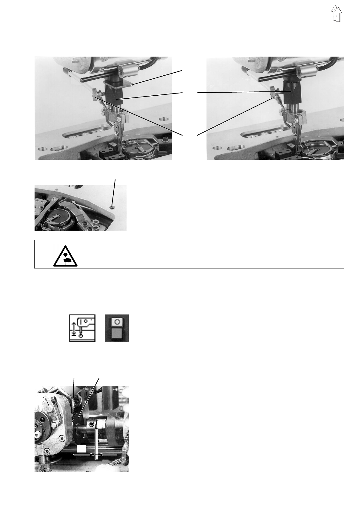
2. Machine head (Class 806-1 1 1)
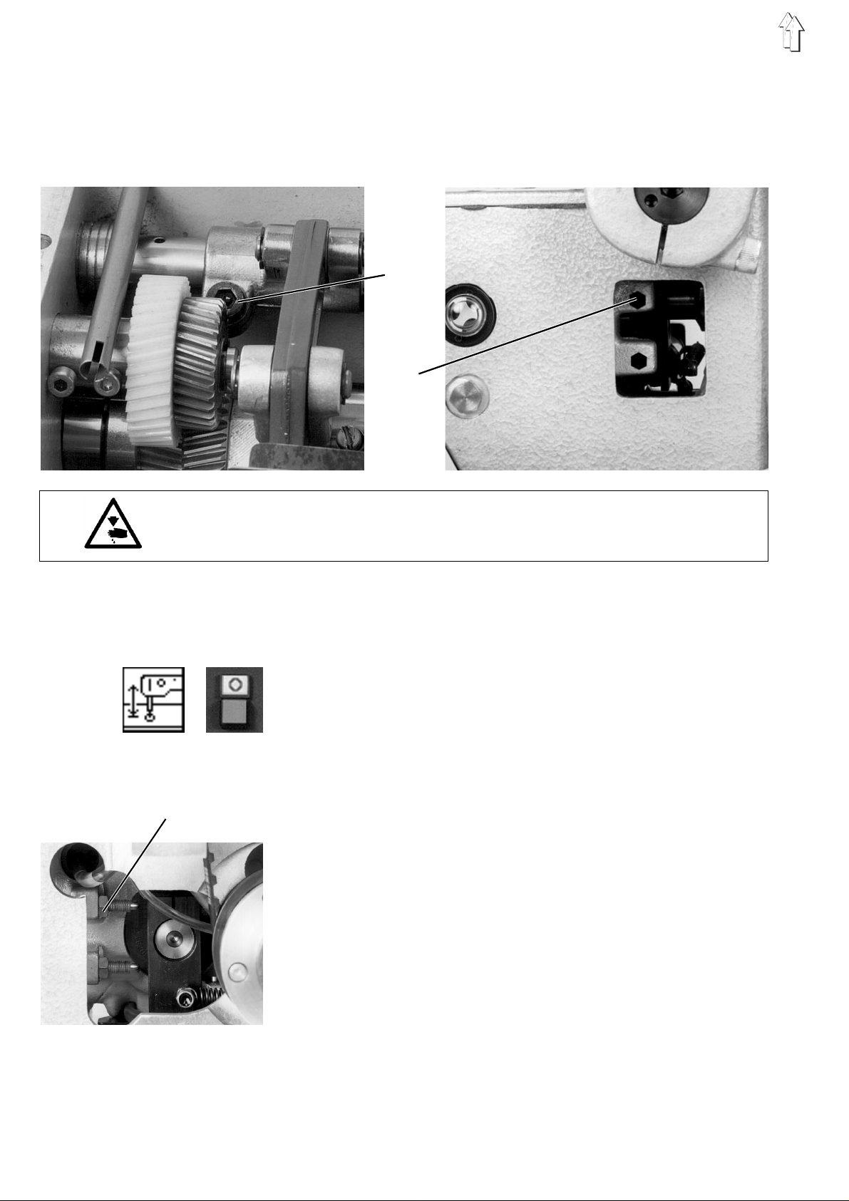
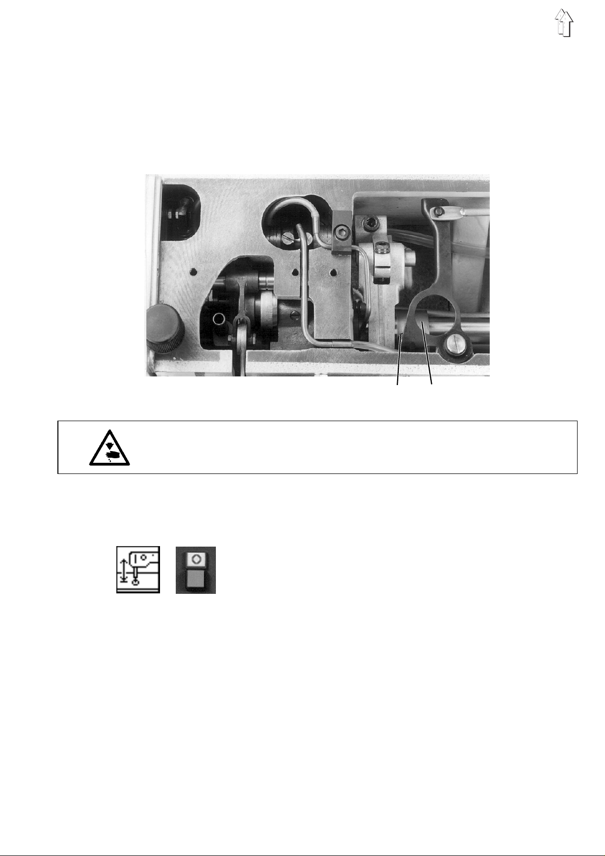
2.1 Stitch regulator and transmission lever
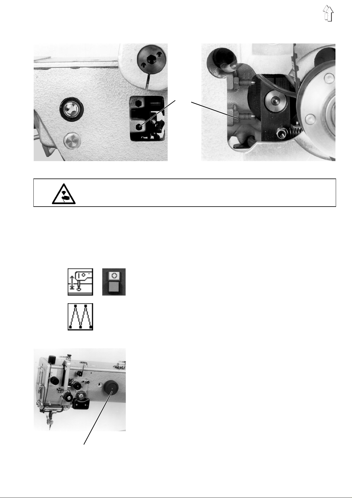
2.1.1 0-position of the stitch regulator
1
2
3
Caution: Danger of bodily injuries !
The machine must be in the position "Safe motor stop " .
Rule and control
The needle bar should not ”oscillate” when sewing without zigzag
function.
–
Lower the sewing head by the function "
sewing head ".
–
Press the key "O".
"Safe motor stop” will be switched on.
–
Unscrew oil pan cover.
–
Introduce hexagon screw screwdriver into the screw 1.
–
Turn the setting wheel of the stitch regulator until the spanner
moves as little as possible..
Correction
–
Loosen counte r nu t 3 .
–
Turn screw 2 accordingly.
–
Tighten counter-nu t 3 .
Lifting/lowering the
6
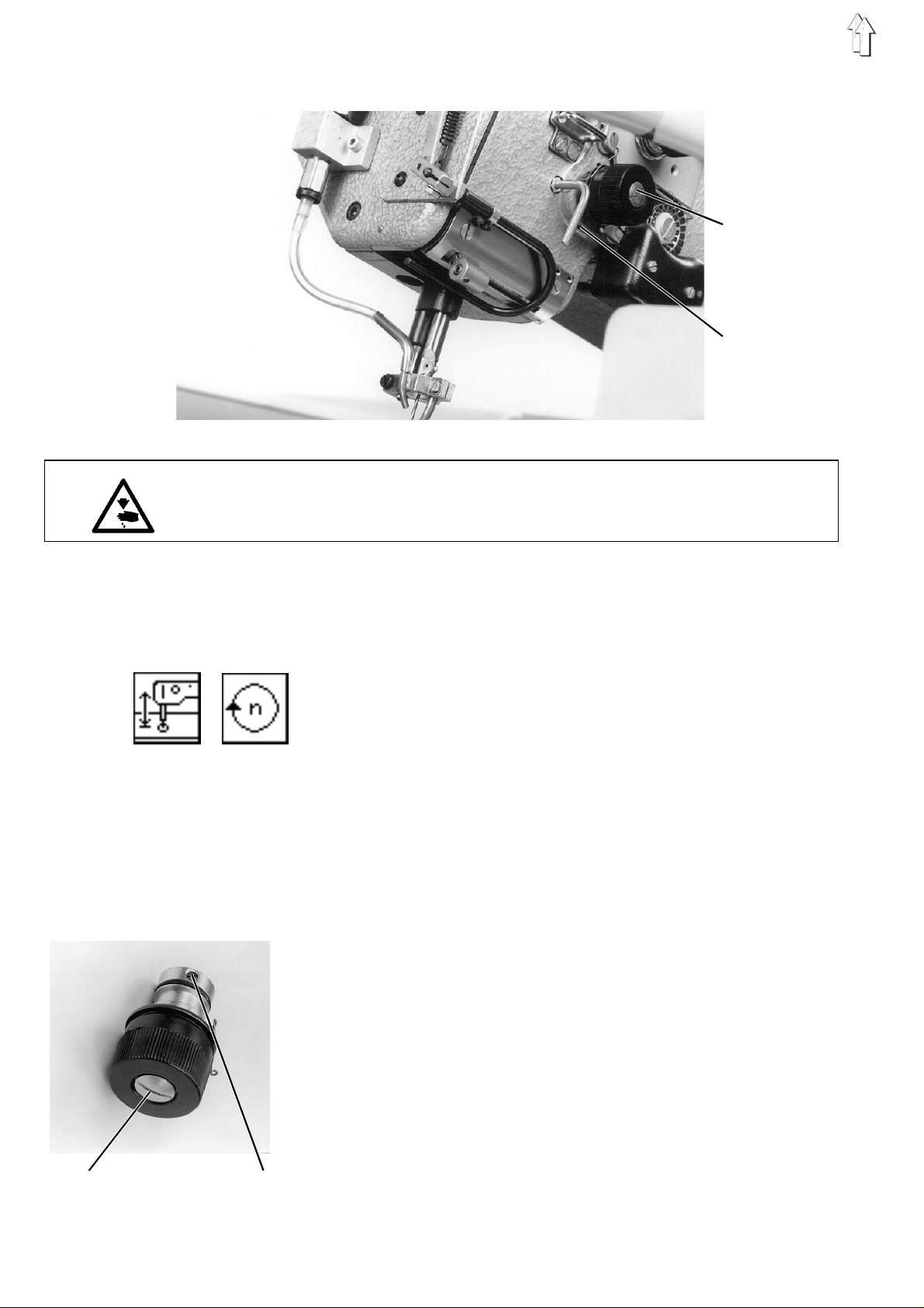
2.1.2 Position of the transmission lever
The lever 2 tr an s mit s th e m ot i on of th e f ee d s h af t 3 to th e ro c k er 1 .
Caution: Danger of bodily injuries !
The machine must be in the position "Safe motor stop".
Rule and control
The lever 2 sh ou l d b e i n v ert i c al p os ition when the zi g z ag fu nc t i on is
snot activated.
Correction
–
Lower the sewing head by the fu nc t i on "
sewing head
–
Press the key "O".
"Safe motor stop " will be switched on.
–
Loosen screw 4.
–
Turn the lever on the shaft accordingly.
–
Tighten screw 4.
Lifting/lowering the
".
Note
In case of a wrong adjustment, the ”oscillations” of the needle bar and
1
of the throat plate will not be synchronous during the zigzag operation.
2
3
4
7
1
2
3
4
5
6
7
8 9 10 11 1 2 13 14 15
8
16
17
18
19

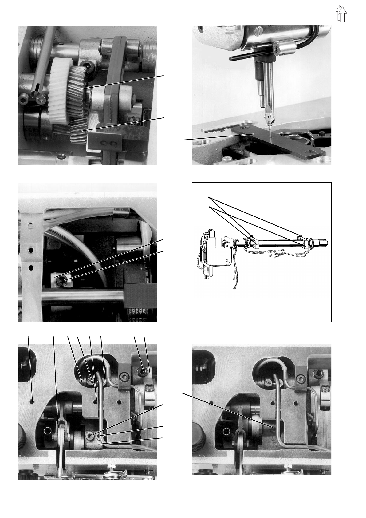
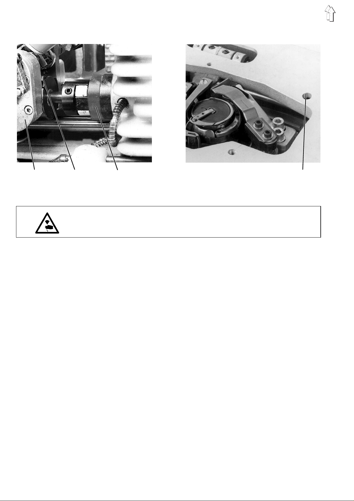
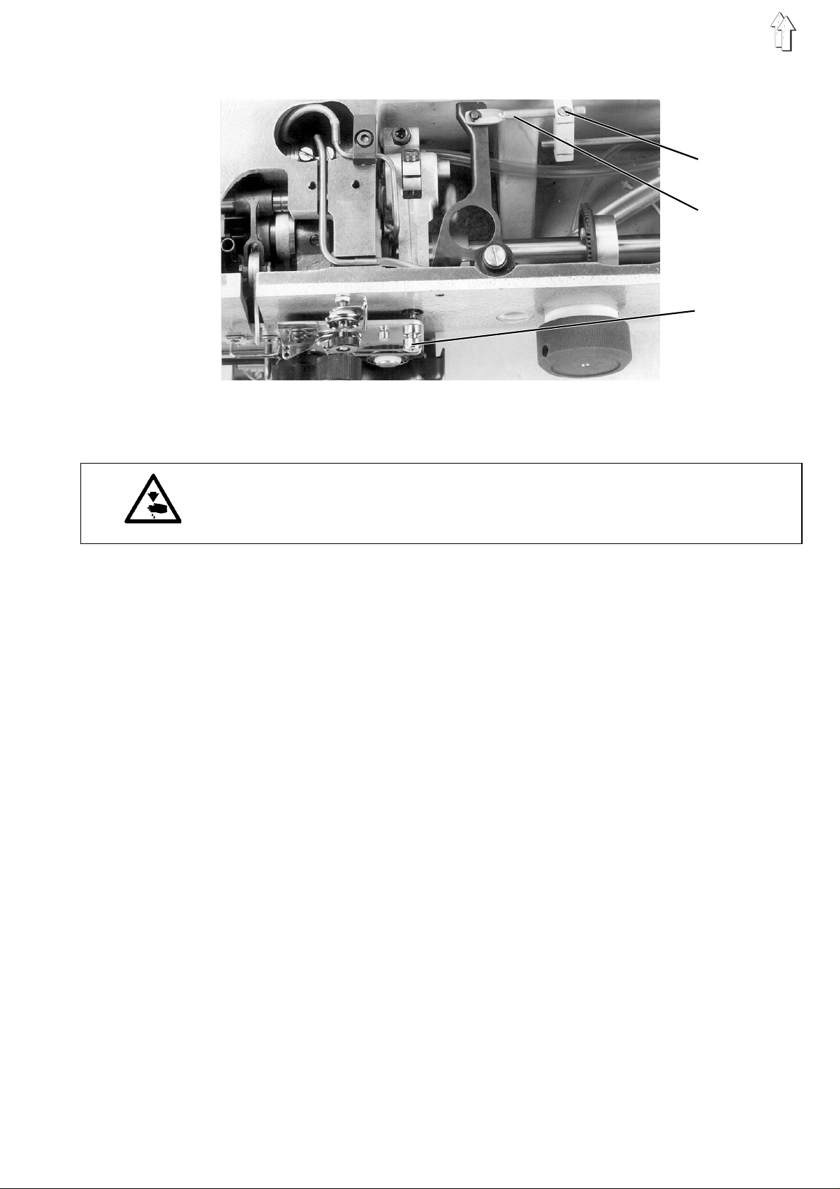
2.2 Rocker and throat plate
2.2.1 General information
2.2.2 Position of the rocker
While the nee dl e ba r an d t he th r oa t p l at e a r e p erforming a comp lete
oscillation movement during the zigzag function, the needle bar will
move 2 times up and down.. This is ensured by the couple of gears 1
and 2, having a transmission ratio of 1 : 2..
Caution: Danger of bodily injuries !
The machine must be in the position "Safe motor stop ".
Rule and control
The needle sh ou l d s t i tch i nt o the centre of th e 2 mm bo r e-h ol e of the
gauge 3 (part n o. 08 04 40 0270) when the mac h i ne i s ou t o f t he z igz a g
mode.
Correction in X direction
–
Lower the sewing machine by the function "
sewing machine".
–
Press the key "O".
"Safe motor stop " will be switched on.
–
Loosen the screws 4 on the two setting blocks 5.
–
Loosen the clamping screw 7 on the drive level 6.
–
Loosen the screws 8 and 12 on the bearing for the thread take-up
lever guide 5.
–
Loosen the cl a mp i ng s c rews 17 and 18 on the ar m s ha ft c ran k 19 .
–
Loosen slightly the position screw 16 on the arm shaft crank.
–
Proceed to a c orr e c ti o n.
If required, shift the sewing foot stroke shaft 10 in the axial
direction after having loosened following screws:
The screws on th e two setting ri n gs 11 and 13, the sc r ew 14 on th e
block 15.
–
Retighten al l th e p rev i o usl y lo os e ne d s cr e w a nd no te th e f oll o wi n g:
Axial fixi ng of the rocker,
horizontal position of the setting block 5 ,
correct position of the wicks,
minimum possible play of the thread take-up lever guide 9.
Lifting/lowering the
Correction in Y direction
–
Lower the sewing head by the fu nc t i on "
sewing head
–
Press the key "O".
"Safe motor stop " will be switched on.
–
Loosen the clamping screw 7 on the drive lever 6.
–
Change the rocker position accordingly.
–
Retighten t he c l am pi n g s cr e w.
Note
Following a correction in X-direction, check and, if required, correct
the distance be tween the hook and the needle.
".
Lifting/lowering the
9
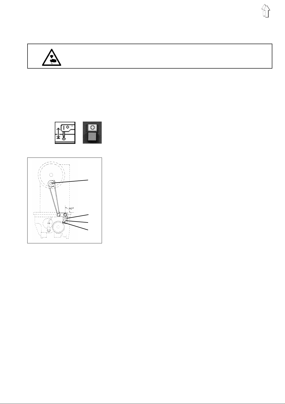
2.2.3 Timing the rocker oscillation
2 3
1
Caution: Danger of bodily injuries !
Do not introduce your hands into the moving machine parts.
Rule and control
–
In the zigzag mo de , when stitchi ng i nt o t he up pe r ba rtack point,
the needle should be ”driv en i nw ar d s to the same extent a s i t i s
driven when stitching into the lower.
–
Both bartacking stitches should be equidistant top the "zero stitch”.
–
Lower the sewing head by the function "
sewing head
–
Press the key "O".
"Safe motor start " will be switched on.
–
Place a piec e of pa pe r on to th e f ab r i c r es t an d h ol d i t t he r e.
–
Turn the setting wheel 1 for determining the position of the "zero
stitch".
–
Select the "
–
Turn the setting wheel 1.
Correction
–
Loosen screw 2.
–
Turn the gear 3 on the hook driving shaft 3 accordingly.
–
Retighten the screws 3.
".
zigzag
" function.
Lifting/lowering the
10
ATTENTION !
A wrong setting can cause needle breakage.
2.2.4 Range of the rocker oscillation (throw width)
1
Caution: Danger of bodily injuries !
The machine must be in the position "Safe motor stop ".
Rule and control
In the zigzag mo de of the machine, the " up pe r " an d t he " l ow er"
stitches on a p i ec e of pa pe r sho ul d ha v e a di s t an c e o f 5 mm .
In a set pocket, this will result in a throw width of about 3 mm,
depending on th e t y pe of fa br ic a nd th r ea d a nd on th e thread tensio n.
–
Lower the sewing head by the fu nc t i on "
sewing head
–
Press the key "O".
"Safe motor stop " will be switched on.
–
Select the "
–
Place a piece of fabric onto the fabric rest and hold it there.
–
Turn the handwheel.
Correction
–
Turn the counter-n ut 1 a nd th e s t op s c rew 1 accordingl y.
".
zigzag
" function.
Lifting/lowering the
2
11
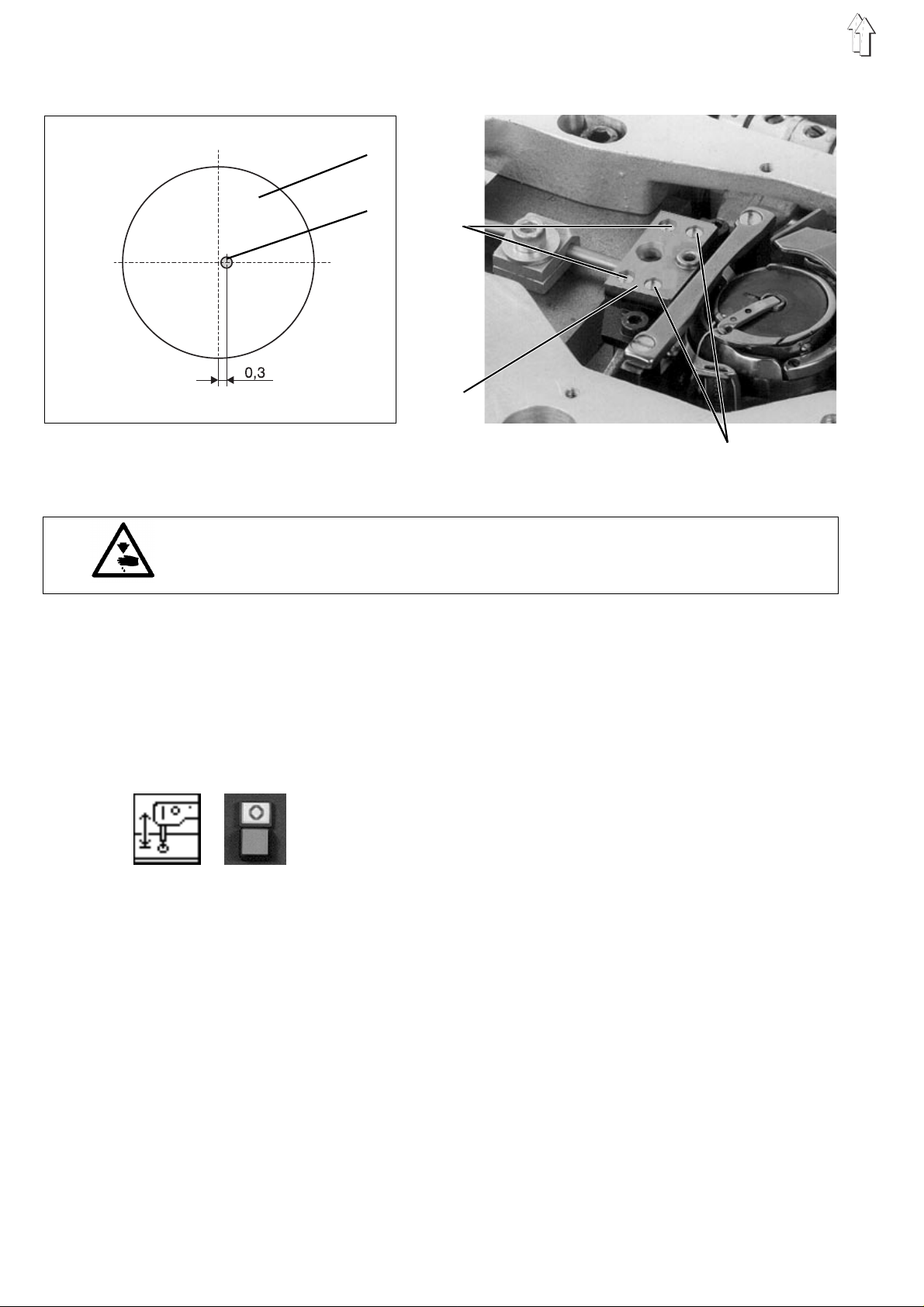
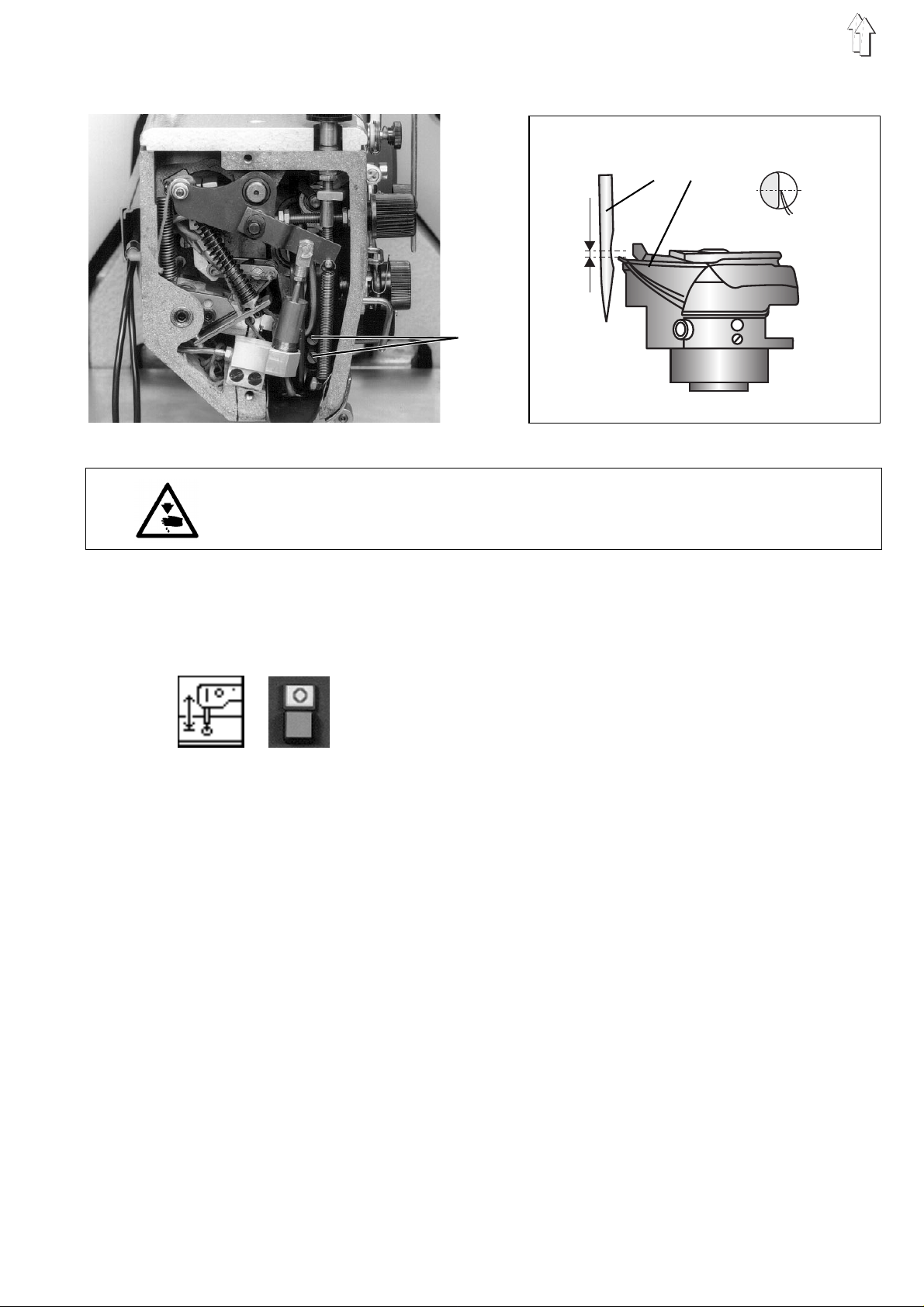
2.2.5 Horizontal position of the throat plate
1
2
3
4
5
Caution: Danger of bodily injuries !
The machine must be in the position "Safe motor stop ".
Rule and control
–
In X-directi o n:
In the loop formation position – or a bit later – the needle shank 2
should be distanced 0.3 mm from the right side of the stitch hole 1.
–
In Y-direction:
In this direction, the needle should stitch in the middle of the stitch
hole.
Correction
–
Lower the sewing head by the function "
sewing head
–
Press the key "O".
"Safe motor stop " will be switched on.
–
Loosen the screws in the bore-hole 3 and 5 and change the
position of th e throat plate 4 a c c ord i ng l y.
–
Retighten the screws in the bore-holes 3 and 5.
".
Lifting/lowering the
12
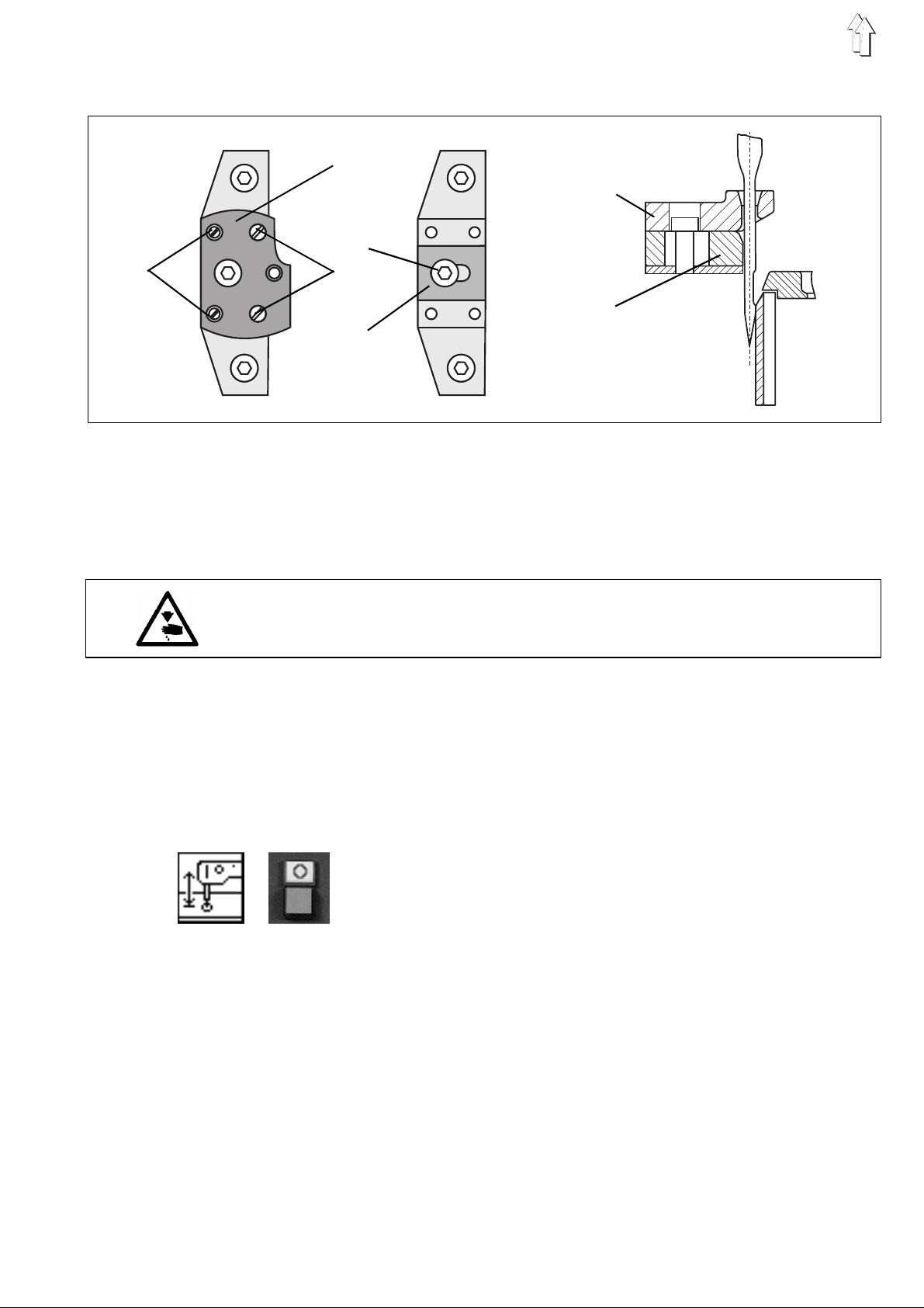
2.2.6 Height of the throat plate
1 2
Caution: Danger of bodily injuries !
The machine must be in the position "Safe motor stop ".
Rule and control
The stitch h ol e mu shr o om bu tt on must stand 0,5 mm un de r th e t op of
the fabric rest .
Correction
–
Lower the sewing head by the fu nc t i on ”
sewing head
–
Press the key "O".
"Safe motor stop " will be switched on.
–
Loosen screw 1.
–
Turn the block 2 accordingly.
–
Retighten t he s c rew 1.
".
Lifting/lowering the
13
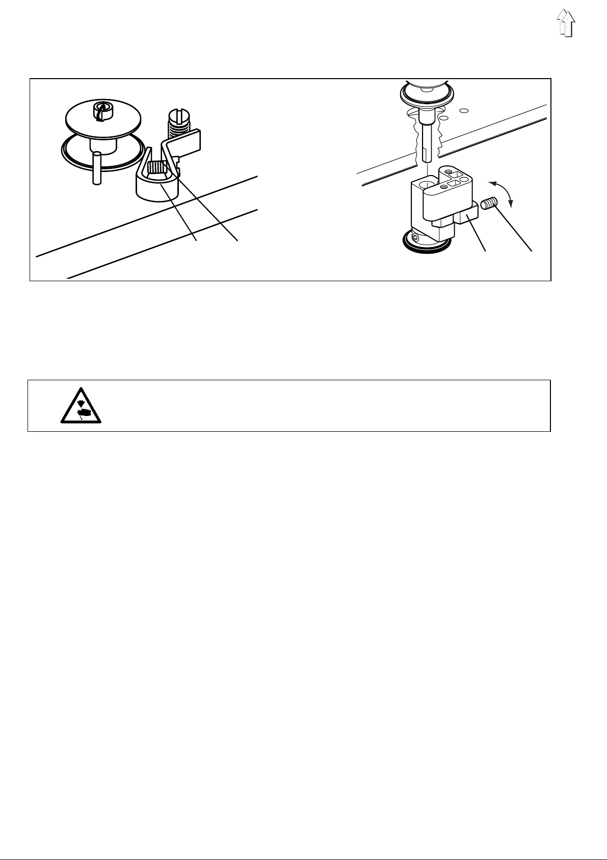
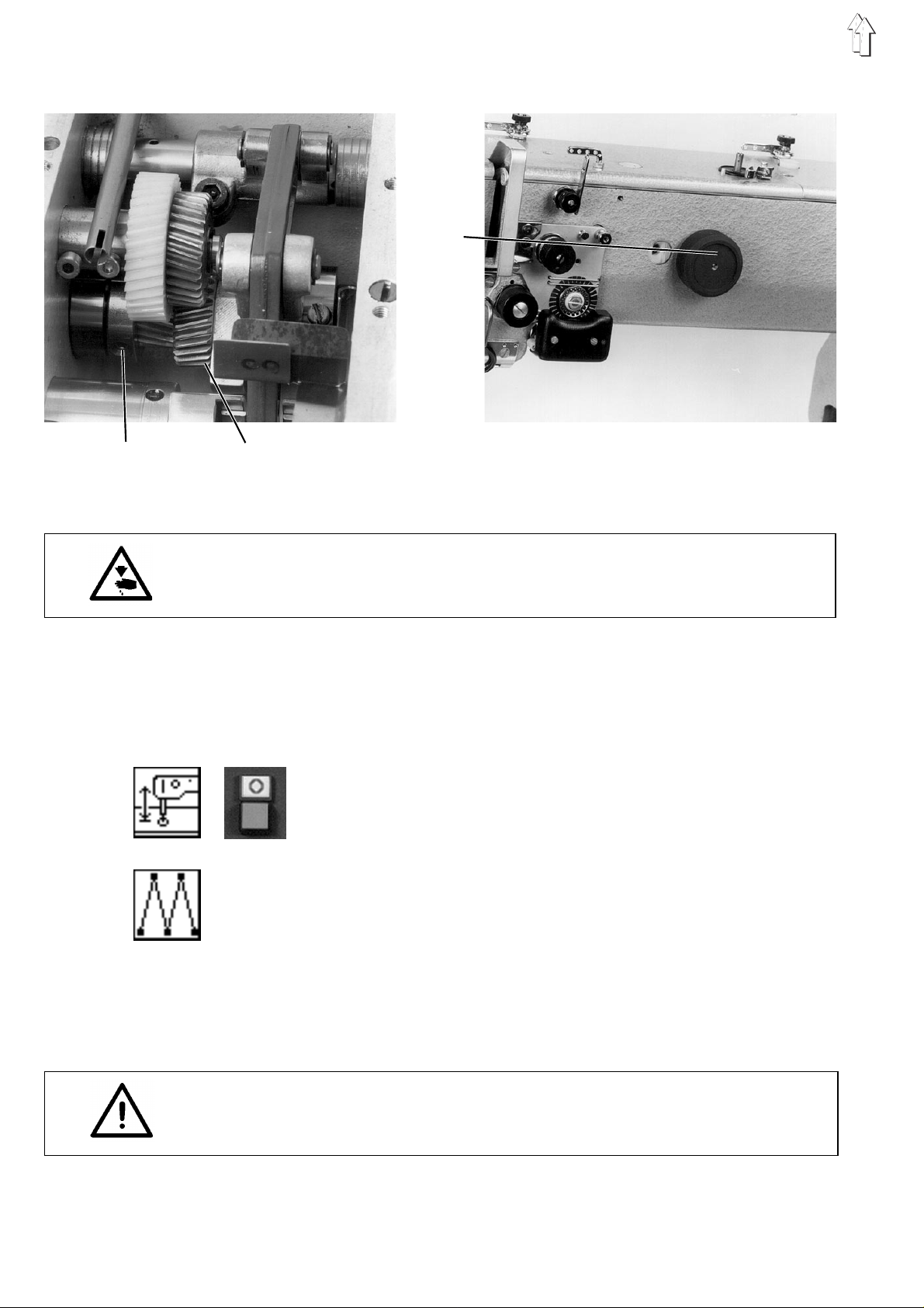
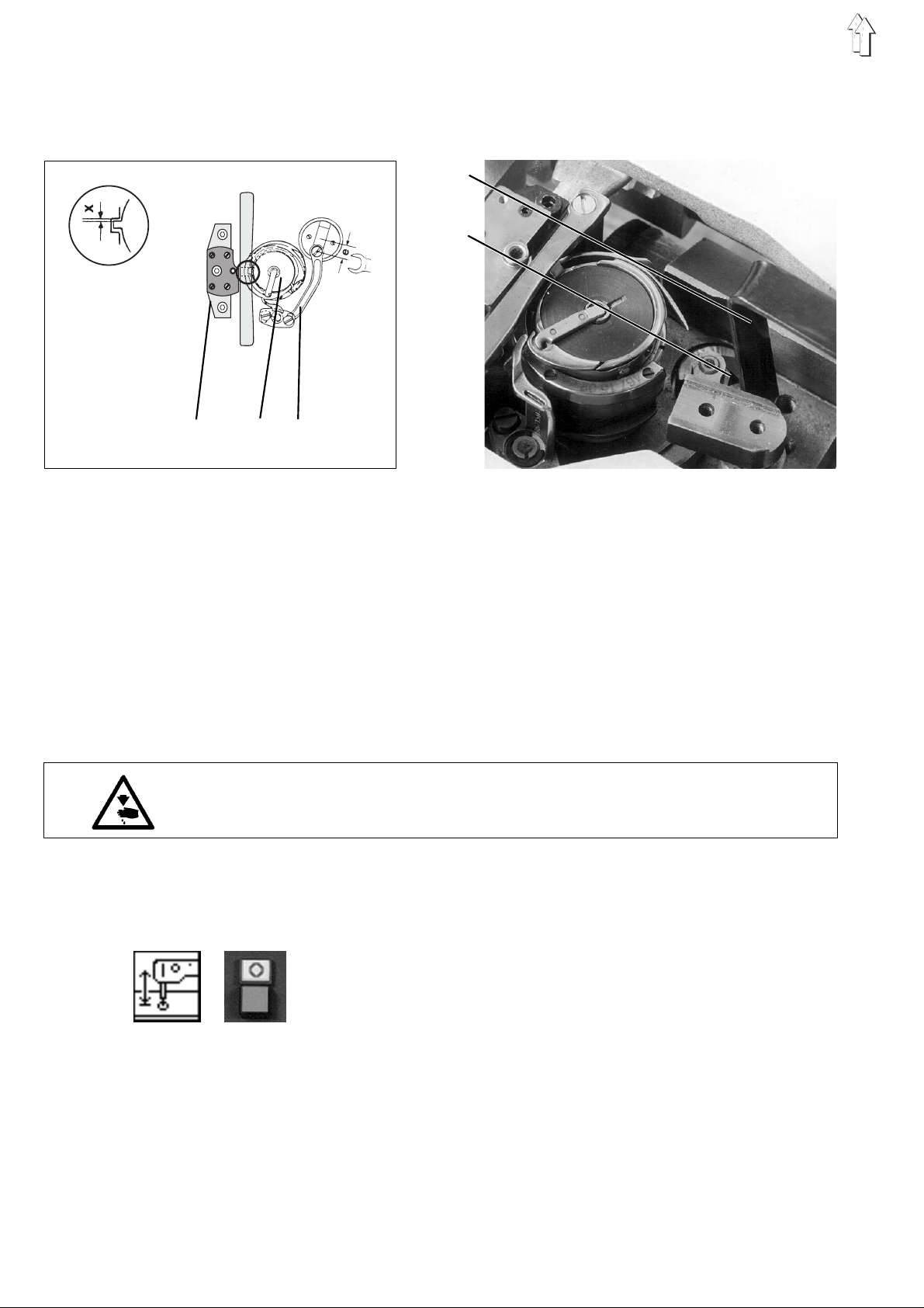
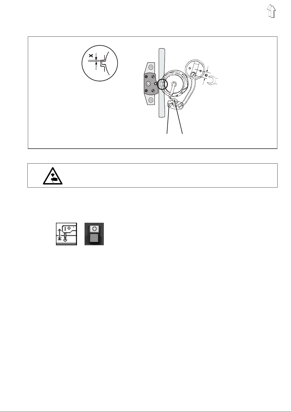
2.3 Adjusting the bobbin winder
B
A
1 2
Rule and control
The bobbin wind er s h ou ld s t op au to ma ti ca l l y wh en th e b ob bi n wh en
the thread wo un d o n t he bo bb i n i s a bo ut 0, 5 m m f r om i ts ri m .
The thread should be wound cylindrically.
Caution: Danger of bodily injuries !
The machine must be in the position "Safe motor stop ".
Correction
1. Small changes in the filling amount
–
Regulate the bo bb i n w i nd er f l ap 1 b y th e sc r e w 2 .
2. Major changes in the filling amount
–
Remove arm cover.
–
Loosen screw 4.
–
Turn tripping cam 3 .
In A arrow direction: for small filling amount
In B arrow direction for major filling amount
–
Retighten screw 4.
–
Replace arm co v er.
3 4
14
2.4 Hook, needle bar , hook guard and needle guide
2.4.1 Loop stroke
1
2
3
4
The loop stroke is the distance covered by the needle bar from its
lower dead centre up to the point where the point of the hook coincides
with the middle of the needle.
st
The 1
hook – is located on the flat side of the hook shaft.
Being fixed , t he hook cannot rot at e o n t he s ha ft du r i ng th e s e wing
process. If the hook is jammed, the sliding clutch will react.
screw on the hook – seen in the direction of rotation of the
5 6
0,5
Caution: Danger of bodily injuries !
The machine must be in the position "Safe motor stop".
Rule and control
–
The adjustment of the rocker position must be correct.
–
The loop stroke should amount to 2 mm when the machine in not in
the zigzag mo de .
–
Lower the sewing head by the fu nc t i on "
sewing head
–
Press the key "O".
"Safe motor stop " will be switched on.
–
By means of t he bl o c k 2 (p ar t no .. 0981 150002) pre ss th e g au ge 1
(Part no. 0981 150003) against the rocker.
–
Retighten t he s c rew 3 on the block 2.
–
Remove the gauge 1.
–
Turn the setting wheel in the arrow direction until the block 2 is in
contact with th e ro ck er.
In this position, the hook point should coincide with the middle of
the needle.
Correction
–
Loosen the cl a mp i ng s c rew in the bore-hol e 4 b y a h ex a go n s c re w
screwdrive r (s pa nn er o pe ni n g 5 mm ).
The screw 5 is l o c at ed on th e s e tt i ng r ing 6.
–
Turn the hook on the dri v i n g shaft until the t i p o f the hook stands
against the mi d dl e of the needle.
Ensure that the air gap in the jaw clutch amounts to 0.5 mm.
–
Retighten t he c l am pi n g s cr e w 5 i n t he bo r e- h ole 4.
".
Lifting/lowering the
15
2.4.2 Sliding clutch
1 2 3
Caution: Danger of bodily injuries !
The machine must be in the position "Safe motor stop ".
Rule and control
The sliding clutch should react when the hook is jammed.
Adjust the s l i di n g cl u tc h 3 s o th at i t r e ac t s at a torque of 4 N m.
Correction
–
If the clutch r ea c ts too often, turn- i n th e t wo s c rews (spanner
opening 3 mm) at the on the face of the sliding clutch 3.
two
If the
torque will e increased by about 10 %.
Re-engage the sliding clutch
Following a reaction of the sliding clutch, the latter must be
re-engaged i n t he fo l l ow i ng ma nn er : :
–
Introduce the hexagon screw driver into the screw of the
bore-hole 4 an d i n to th e c lamping screw 2.
–
Turn the handwheel 6 until the clutch is re-engaged.
screws are tu r ne d a qu ar t er ( 1 /4 ) of a re v ol u ti o n, th e
4
16
2.4.3 Needle bar height
2 3
0,3
1
Caution: Danger of bodily injuries !
The machine must be in the position "Safe motor stop ".
Rule and control
In the loop fo rma ti o n p os i t i on , t he ho ok t i p 3 s ho ul d s ta nd mo r e o r l es s
under the midd l e o f t he furrow of the n ee dl e 2. W he n t he ma c hi n e i s
out of the zigzag mode.
–
Lower the machine head by the function "
machine head
–
Press the key "O".
"Safe motor stop " will be switched on.
Correction
–
Loosen the t wo s c rew s 1.
–
Change the height of the needle in the way that the tip of the hook
stands a bit (about 0,3 mm) under the middle of the furrow of the
needle.
Do not turn the nee dle .
–
Retighten t he s c rews 1.
Note
Following a cor r e cti o n, check the posi t i on of th e n eedle guide and o f
the hook guard .
".
Lifting/lowering the
17
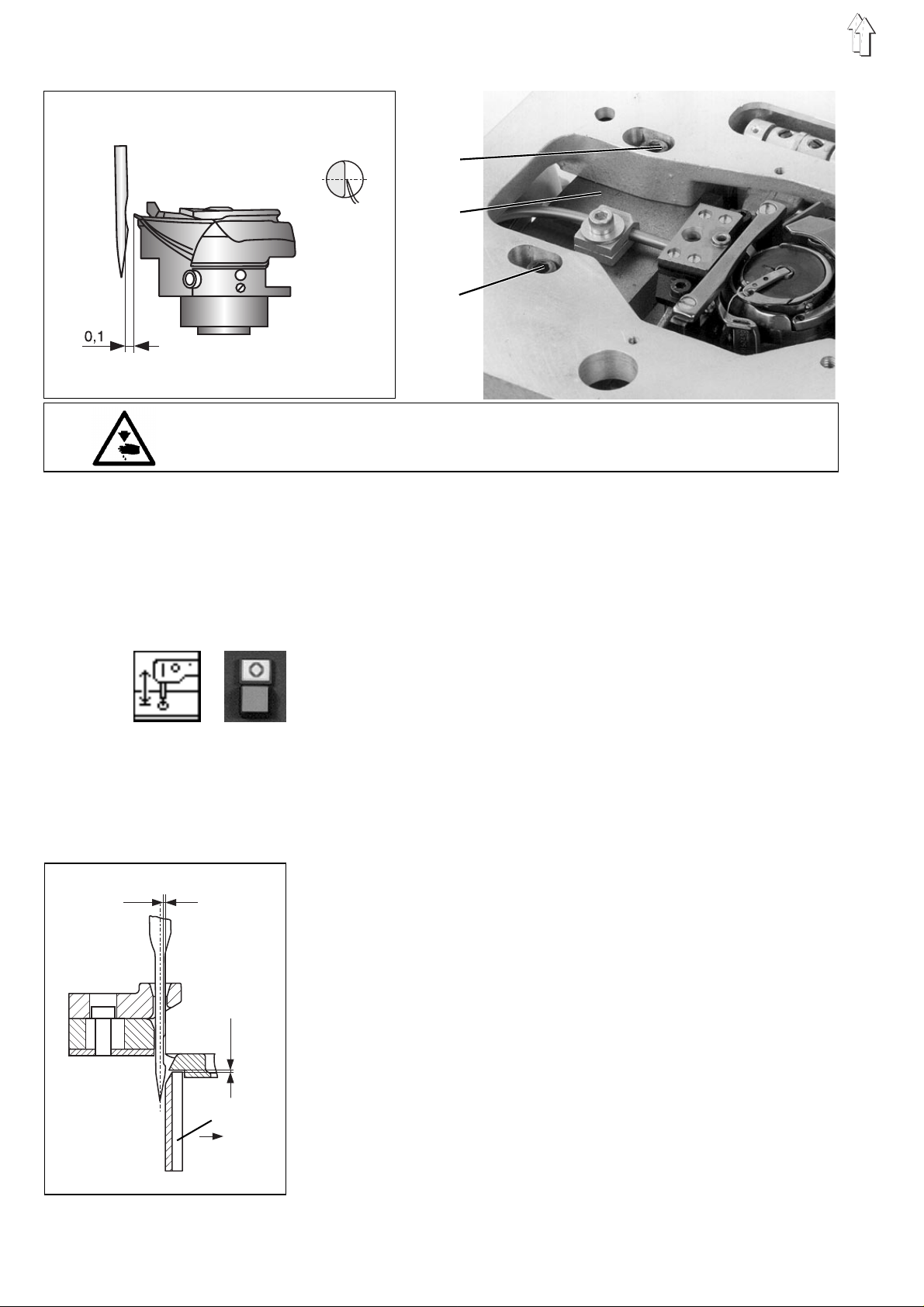
2.4.4 Distance between the hook and the needle
Caution: Danger of bodily injuries !
The machine must be in the position "Safe motor stop ".
The distance between the hook and the needle must be checked after
inserting a ne ed l e t ha t b el o ng s to a d i ffer en t si z e gr o up
(80-110 Nm or 120-140 Nm).
1
2
3
0,1
Rule and control
In the loop fo rma ti o n p os i t i on , t he di s t an c e b et ween the hook and t he
furrow of the needle must amount to 0.1 mm when the machine is out
of the zigzag mo de .
–
Lower the machi ne he ad by t he fu nct i on "
machine head
–
Press the key "O".
"Safe motor stop " will be switched on.
–
Remove the stitch throat.
–
Check the dis t an c e. T he ne ed l e m ust not osculare ne ed l e gu ar d 5.
Correction
–
Move the machi n e i n th e l o op fo r ma ti o n p os i t i on by turning the
handwheel.
–
Loosen the sc r ew s 1 a nd 3.
–
Loosen the sc r ew s 7
–
Remove the stitch throat.
–
Loosen screws of bobbin case retainer 6 and take bobbin case
retainer.
–
Non loosen accessible screws (SW 1,5) of the hook guard 4 to be
laterally displaced.
ATTENTION !
Do not loosen screws securing the vertical position.
–
0,1
4
R
Displace hook g ua rd 4 i n t he dir e c tio n o f R.
–
Displace the hook case 2 sideways until the distance between the
furrow of the ne ed l e a nd th e h oo k ti p am ou nt s to 0. 1 m m.
–
Retighten the screws 1 and 3.
–
Displace the h oo k gu ard ba c kw a rdl y u nt i l th e co ni c a l tip of th e
needle contacts the hook guard, without deflecting the needle.
ATTENTION !
The hook guar d 4 sheet should not to uc h th e h oo k .
–
Tighten scrwes (SW 1 ,5 ) of th e h oo k gu ar d .
–
Reassemble b ob i n c a s e re ta i ne r an d t hr o at pl a te .
".
Lifting/lowering the
18
2.4.5 Position of the needle guide
2
3
1
4
5
2
5
The needle guide 5 should guide the needle during the sewing process
in order to avo i d i t s ex cessive deflec t i on by t he fa br ic . O th er w i s e,
skipped stitches can occur.
The distance between the hook and the needle must be checked after
inserting a needle that belongs to a different size group (80-110 Nm or.
120-140 Nm)
Caution: Danger of bodily injuries !
The machine must be in the position "Safe motor stop "
Rule and control
When the need l e i s i n i ts l o we s t p osi t i on , i t s di s t an c e t o t he ne ed l e
guide should be as s m al l as possible, b ut i t s h ou l d n ot to uc h th e g ui d e.
If the distance is too narrow, the needle may brake in the furrow area..
But if the distance is too wide, skipped stitches can occur, because the
needle woul d b e d ef l ec t ed by t he fa br ic e x c ess i v e l y.
–
Lower the sewing head by the fu nc t i on "
sewing head
–
Press the key "O".
"Safe motor stop " will be switched on.
Correction
–
Loosen the screws 4.
–
Remove the t hr o at pl a te 2.
Ensure that the positioning aids 1 are well fastened and cannot be
displaced.
–
Loosen the cl a mp i ng s c rew 3.
–
Change the position of the needle guide 5 accordingly.
–
Tighten the clamping screw 3.
–
Replace th e t hro at plate 2.
Make sure that the positioning aids 1 are located in the bore-holes
of the throat pl a te .
–
Tighten the screws 4.
".
Lifting/lowering the
19
2.5 Bobbin case lifter
2.5.1 General information
3 4 5
1
2
The thread tak e -up l ev e r s ho ul d pa ss th e t hre ad be tween the bobbi n
case 4 and its su pp or t 3. F or e ns u ri ng a f r ee th rea d p as sa ge , the
bobbin case must be lifted in this moment by the bobbin case lifter.
This will ensure the desired seam pattern with the lowest possible
thread tension.
Wrong adjustments may have following effects:
–
Thread breaka ge
–
Eyelets on the fabric underside
–
High noise level
2.5.2 Amount of the finger travel
Caution: Danger of bodily injuries !
The machine must be in the position "Safe motor stop ".
Rule and control
The support of the lever 5 should be eccentric. This will be ensured
when the nut 2 is f l ush wi t h t he ou te r ed ge of the shaft.
–
Lower the sewing head by the function "
sewing head
–
Press the key "O".
"Safe motor stop " will be switched on.
Correction
–
Loosen the nu t 2 by t he s pe ci al s p an ne r 1a nd change the
eccentricity accordingly.
–
Tighten the nut 2.
Note
Following a cor r e cti o n, check the trav e l am ou nt an d t he tr a v el m om en t.
".
Lifting/lowering the
20
2.5.3 Amount of the lifting gap (position of the finger travel)
1 2
Caution: Danger of bodily injuries !
The machine must be in the position "Safe motor stop ".
Rule and control
The X distance between the lifted bobbin case and its holder should
correspond to th e s i z e of th e t hr e ad us e d.
–
Lower the sewing head by the fu nc t i on "
sewing head
–
Press the key "O".
"Safe motor stop " will be switched on.
Correction
–
Loosen screw 1.
–
Change the position of the finger 2 accordingly.
–
Tighten the screw.
".
Lifting/lowering the
21
2.5.4 Timing the bobbin case lifting
Caution: Danger of bodily injuries !
The machine must be in the position "Safe motor stop ".
1
2
3
4
Rule and control
The bobbin case must be in its lifted position when the thread passes
between the bo bb i n c a s e 3 an d i t s support 4.
–
Lower the sewing head by the function "
sewing head
–
Press the key "O".
"Safe motor stop " will be switched on.
–
Turn the handwheel.
–
Watch the thread passage.
Correction
–
Loosen the two screws 1.
–
Turn the handwheel until the hook tip, after picking up the loop, is
in its ”3 o’clock ” position.
–
Turn the shaft 2 by a hexagon screw spanner (spanner opening 2,5
mm) until the finger stands at the front inversion point, where the
case is completely lifted.
–
2 Tighten the screw 1.
".
Lifting/lowering the
22
2.6 Sewing foot
2.6.1 General information
The adjustment of the upper and lower sewing foot travel position is
described under chapter 6.2.6 of the Operating Instructions.
2.6.2 Timing the sewing foot movement
1 2
Caution: Danger of bodily injuries !
The machine must be in the position "Safe motor stop ".
Rule and control
The sewing foot should start moving upwards at the moment of the
loop formation.
–
Lower the sewing head by the fu nc t i on "
sewing head
–
Press the key "O".
"Safe motor stop " will be switched on.
Correction
–
Loosen the t wo s c rew s 1.
–
Turn the eccentric 2 on the shaft accordingly.
–
Tighten the screws 1.
".
Lifting/lowering the
23
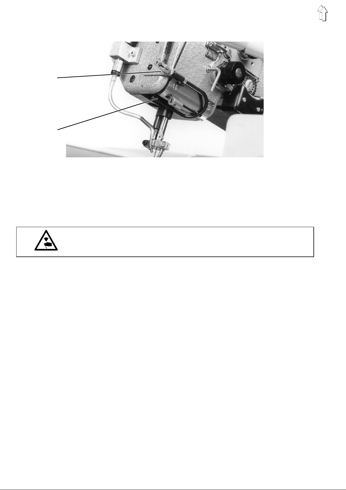
2.7 Thread take-up spring
1
2
Caution: Risk of Injury !
The machine m us t be i n t he po s i tion "Secured st op of mo tors".
3 4
Rule and control
Adjust the tra v el a nd th e t en s i on of th e t hre ad ta k e-u p s p ri ng i n a wa y
that at the moment when the spring reaches its lowest position, the
eye of the stitching needle is disappearing in the fabric.
–
Lower the sewing head by the function "
sewing head
–
Select the "
–
Enter the value 70 by the numerical keys and confirm by the
RETURN
–
Press key "F2" for starti ng th e se wi n g p roc e s s.
–
Watch the thread take-up spring.
–
Press key "F3" for stoppi n g t he s ew i ng ma c hi n e h ea d.
Correcting the travel
–
Loosen slig ht l y th e sc r e w 2 on th e a r m 1 by u s ing a hexagonal
screw spanner.
–
By means of th e b ol t 1, turn the entire thread tension un it
accordingly.
–
Tighten screw 2.
Correcting the tension
–
Press the key "O".
"Safe motor stop " will be switched on.
–
Loosen the sc r ew 2 o n t he ar m 1.
–
Pull out the thread tension unit.
–
Loosen the sc r ew 4.
–
Turn the bolt 3 accordingly.
–
Tighten the screw 4.
–
Replace the thread tension unit.
–
Tighten the screw 2.
speed
key.
".
" function.
Lifting/lowering the
24
2.8 Lifting the thread tensioner
The thread tensioner will be lifted during the cutting process or after
pressing th e b ut to n 3 on th e s u pp or t i ng pl a te .
Caution: Danger of bodily injuries !
Turn off the main swit ch.
Switch off the machine before adjusting the lifting of the thread
tensioner.
1
2
3
Rule and control
The thread mus t pa s s fr e el y t hro ug h the lifted tens i o ne r du ri ng th e
cutting process..
–
By means of the traction rod 1, lift the thread tensioner as far as
possible.
Correction
–
Loosen the screw 1.
–
Change the position of the traction rod 2 accordingly.
–
Tighten the screw 1.
25
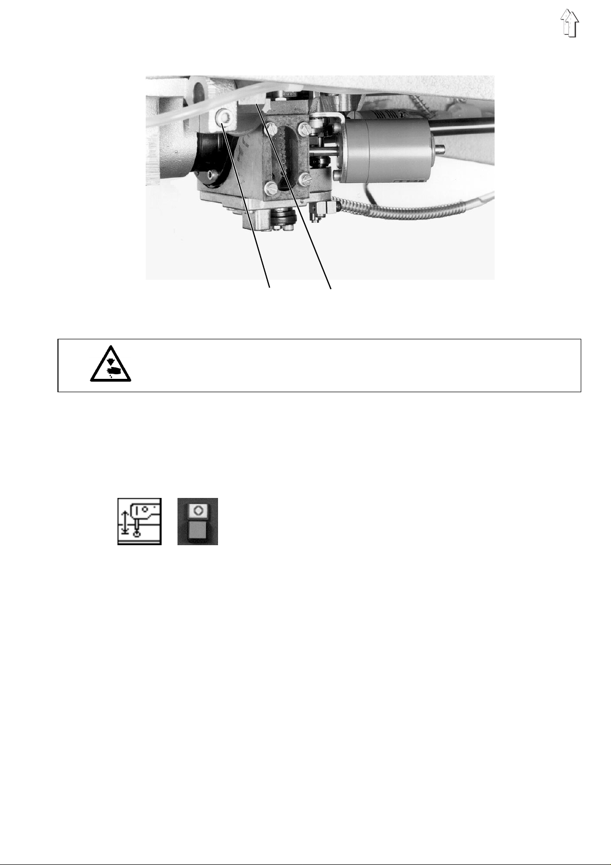
2.9 Thread advancing device
1
2
During the cutting process, the thread advancing device 2 will be
moved forwards after picking up the loop, and it will be returned during
nd
the 2
The thread advancing device has been timed by the control unit. No
change is possible.
The thread adv a nci n g d ev i c e en s ure s a d ef i ne d t hr e ad l en gt h r e qu i red
for starting the seam and it compensates for any thread elongation.
movement phase of the thread cutting knife
Caution: Danger of bodily injuries !
Turn off main switch.
Turn off the machine before adjusting the thread advancing device.
Rule and control
The thread advancing device 2 should advance enough thread to meet
the following requirements for the next sewing cycle :
–
Safe seam be gin ni n g.
–
Pulling the thread end under the fabric.
–
No "thread def l ec t i on " i nt o t he ho ok .
Correction
–
Loosen the sc r ew 1.
–
Change the pos ition of the thre ad ad v an c i ng de v ic e 2 ac c o rdi n gl y.
–
Tighten the screw 1.
26
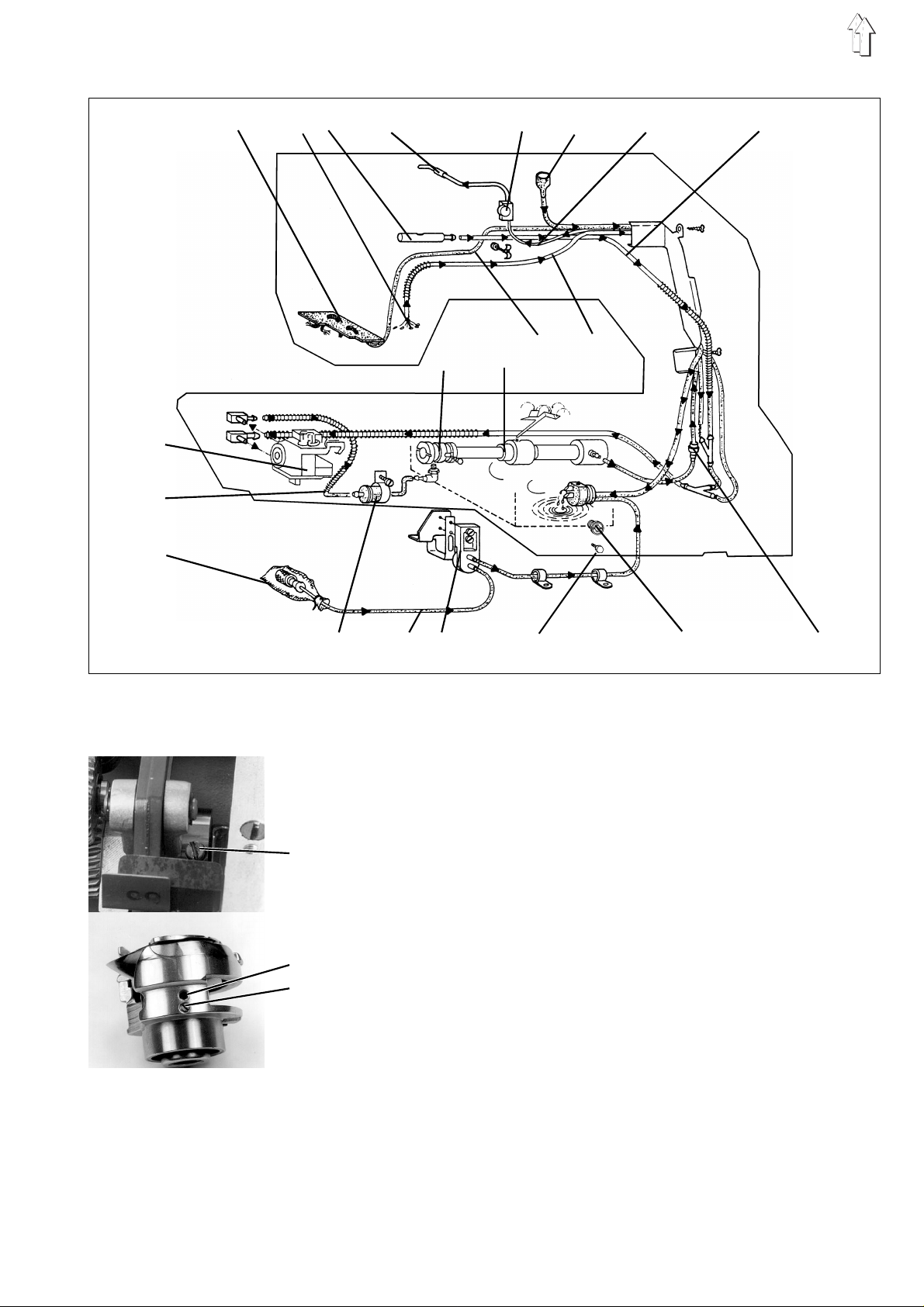
2.10 Lubrication
17
16
1 2 3 4 5 6 7 8
18 19 2 0 21
15
2.10.1 General information
14 13 1 2 11 10 9
–
The wicks used for the lubrication of the respective elements in the
machine head s h ou l d n ot to uc h th e r e - ci r cul a ti o n wick.
–
The plastic cap on the hook impedes the suction of dust and fluff
into the hook case by the vacuum pump.
–
22
23
24
The oil splash screw 22 ensures that enough oil is supplied to the
collecting sheet even if the oil level is very low..
–
When comple ti n g t he machine or foll ow i ng a l o ng er m ac h i ne stop,
lubricate the ”dried up” wicks before restarting the machine,
because an in s uffi c ien t lu br i c a ti o n ca n c a us e da ma ge s .
–
The slotted s c rew 24 under the lubri c a ti o n a dj u s tm en t s cr e w 2 3
can be turned out, so that any obstructions of the oil ducts in the
hook race can be eliminated by a bl o wi n g g un .
Turn-in the screw 24 c om pl e te l y.
27
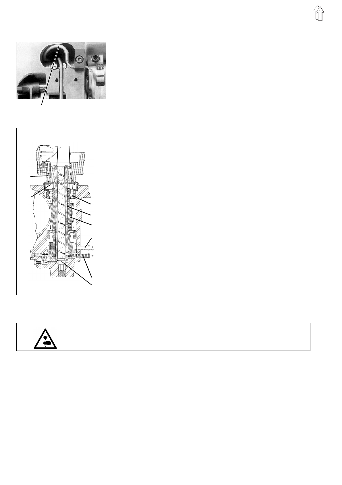
2.10.2 Mode of function
25
Oil supply from the sump to the sewing head
The oil passes from the oil sump to the cavity in the sewing head
through the spiral grooves in the hook driving shaft 19 and through the
duct 7. The ch ec k v a l v e 9 , c o nt ai n ed i n t hi s d uct, avoids the oil
backflow whe n the machine is out of operatio n. . T h e oi l sup pl y th r ou gh
this duct ca n b e c o nt rol l e d b y th e s i g ht gl a s s 5.
Most of oil delivered by the brass tube 4 flows into the bore hole of the
hollow shaft 3. . Th i s ho ll ow s ha ft c onta i ns a wi ck , th at pa s ses th e oi l to
the lubrica ti o n p oi n ts o f t he fo ot l i ft i ng me c ha ni sm and to the sump in
the sewing head.
From here, the oil is conducted through the wicks to the articulations
of the foot lifting mechanism and to the rocker. The foot lifting
eccentric is lubricated by the wick 25, sucking the oil out of the cavity.
35
34
26 27
28
29
30
31
32
33
Oil supply from the machine head to the hook case
The oil splas h ed i n t he s ew i ng he ad is picked up b y th e f el t , p as s ing
the oil to the lower wick, which in turn delivers the oil to the hook case.
The oil dropping from the brass tube 4 into the cavity is collected by
the felt pla te 1, pa s s ing then via the duc t 2 0 t o t he ho ok c a s e.
Oil supply to the hook
The oil returned from the sewing head flows through the duct 32 into
the hook case. Here, the oil can rise up to the level of the suction
pipe 31.
The hollow ho ok s h af t 2 3 c o nv e ys th e o i l v i a t he s pir a l gro ov e s of th e
fixed shaft 3 3 t o the upper vesse l 26 of th e h oo k . F ro m h er e , t he oi l
passes thro ug h t he bo r e-h ol e 27 i nt o t he l ower vessel 34. The sm al l e r
portion of this oil is conveyed by centrifugal force through an oil pipe
35 to the hook race. The major part of the oil flows again down and
lubricates the gears 30 and the ball bearing 28.
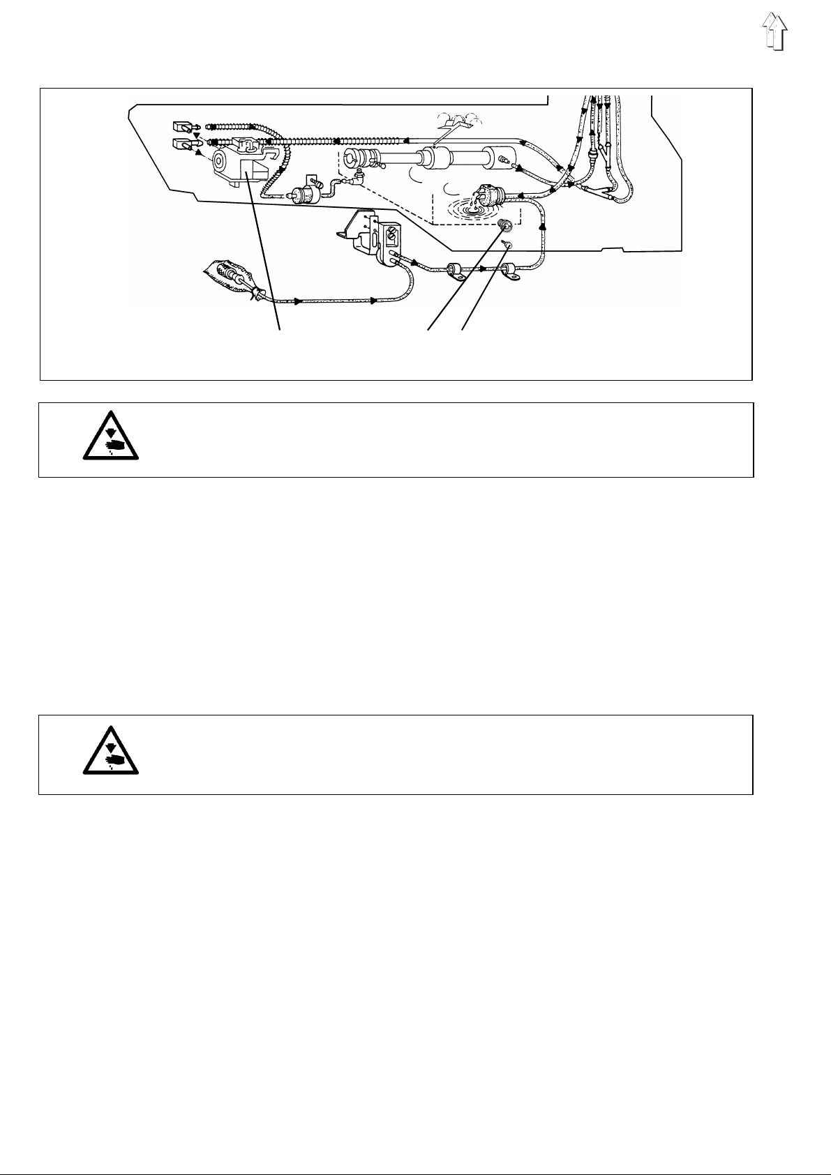
Oil backflow from the hook case to the oil sump
The pump 18 on the hook driving shaft sucks the oil from the hook
case via the pipe 16 back to the oil sump.. The filter 14, contained in
this pipe, intercepts soil particles and avoids thus disturbances of the
pump functions. The pump 12 sucks the oil from the outer plastic tray
via the oil f el t 15 an d v i a th e d uc t 15 ..
2.10.3 Checking oil level and oil supply
Caution: Danger of bodily injuries !
The machine must be in the position "Safe motor stop ".
–
Check the oil level in the oil sump through the sight glass 10 while
the machine i s o ut of operation.
Top up if the oil level is in the lower third of the sight glass.
–
Check the oil s u pp l y to th e s e wi n g hea d t hr o ug h t he si gh t g l ass 5
while the sewing machine is in operation, e.g. during the automatic
cycle.
–
Check the oil level through the sight glass 17 of the hook case
when the latter is in the sewing position and the sewing machine is
out of opera ti o n.
28
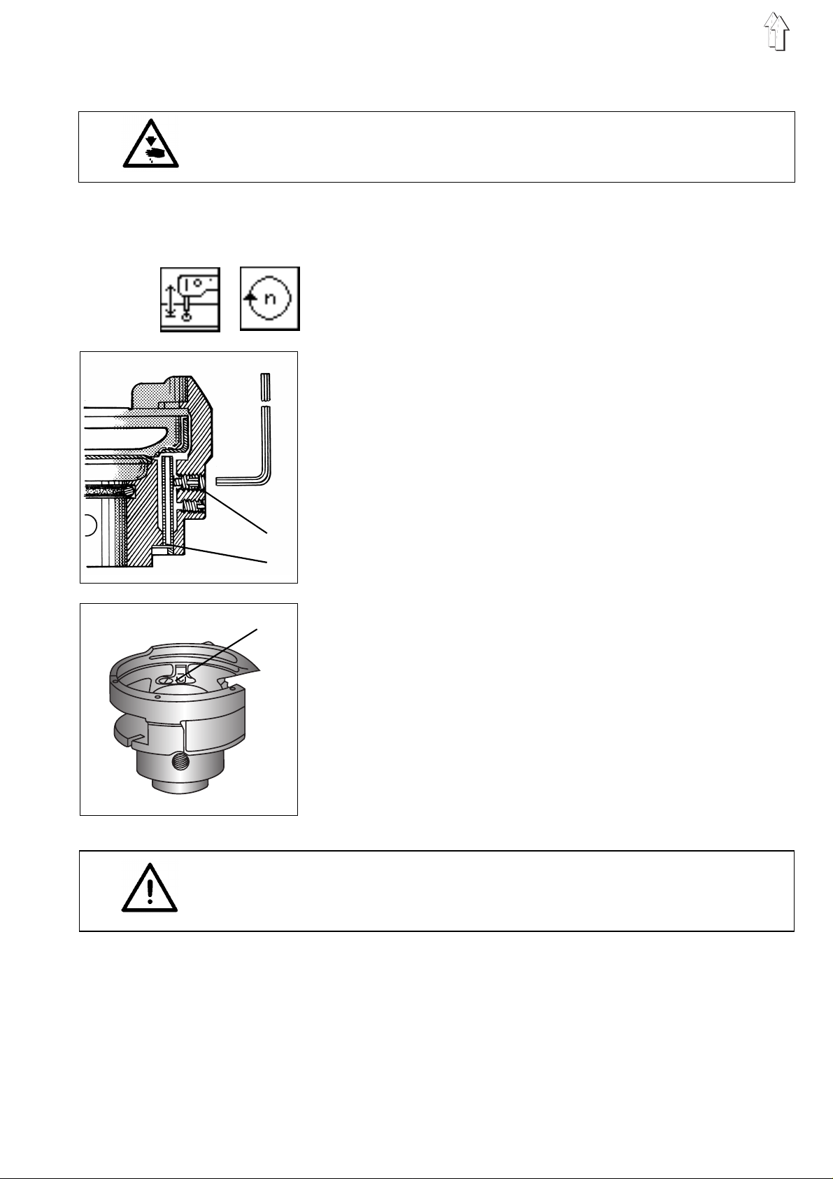
2.10.4 Adjusting the hook lubrication
Caution: Danger of bodily injuries !
Do not introduce your hands into the area of the moving machine parts.
Rule and control
The hook shou l d b e l u bri c a te d s a fe l y wi t h the lowest pos s i ble oil
quantity. (This will also reduce the oil consumption)
–
–
–
–
–
–
–
Lower the sewing machine head by the function "
the machine hea
Select the "
Enter by the numerical keys "4000" and confirm by the "
key
Remove the fabric rest.
Press the key "F2".
Allow the sewing machine operate for about 1 minute.
Press the key "F3".
Hold a piece of paper beside th e h oo k .
Let the machine run at intervals of about 15 seconds by pressing
the keys "F2" and "F3".
The adjustme nt i s cor r e ct i f enough oil is sp l as h ed on to th e p ap er.
speed
d".
" function.
Lifting/lowering
RETURN
"
Correction
1
–
Remove the b ob bi n c ase and the covering s he et 3, for being able
2
3
to recognise the position of the small oil pipe.
–
By means of a s oc ket spanner, having an open i ng of 1.5 mm, turn
back the screw 1 until the small oil pipe 2 does no longer move.
Normally, said pipe will not move when it stands in the middle of
the bore-hole.
–
Tighten the screw 1 until the pipe begins to move.
–
Turn the screw agai n by 1 /8 rev o l ut i on .
The adjusted oil quantity will decrease with the increasing distance
of the pipe fro m the middle of th e b or e -hole.
–
By means of a socket spanner, turn the screw 1clockwise for
reducing the oil quantity.
Turn the screw 1 counter-clockwise for increasing the oil quantity.
Please note the following:
The adjustme nt r an ge be tw ee n the maximum and th e m i ni m um oi l
quantity corresponds to a quarter (1/4) revolution of the screw..
ATTENTION !
The small oil pipe will be squeezed if the screw 1 is turned-in
excessively.
Note
For ensuring a s a fe l ub ri c at i on of th e m ac h i ne du r ing its run-in ti m e,
the factory-se t o i l qu an ti t y i s rat he r hi g h. Th ere fo re, following the
run-in time, check and, if required control the oil quantity.
29
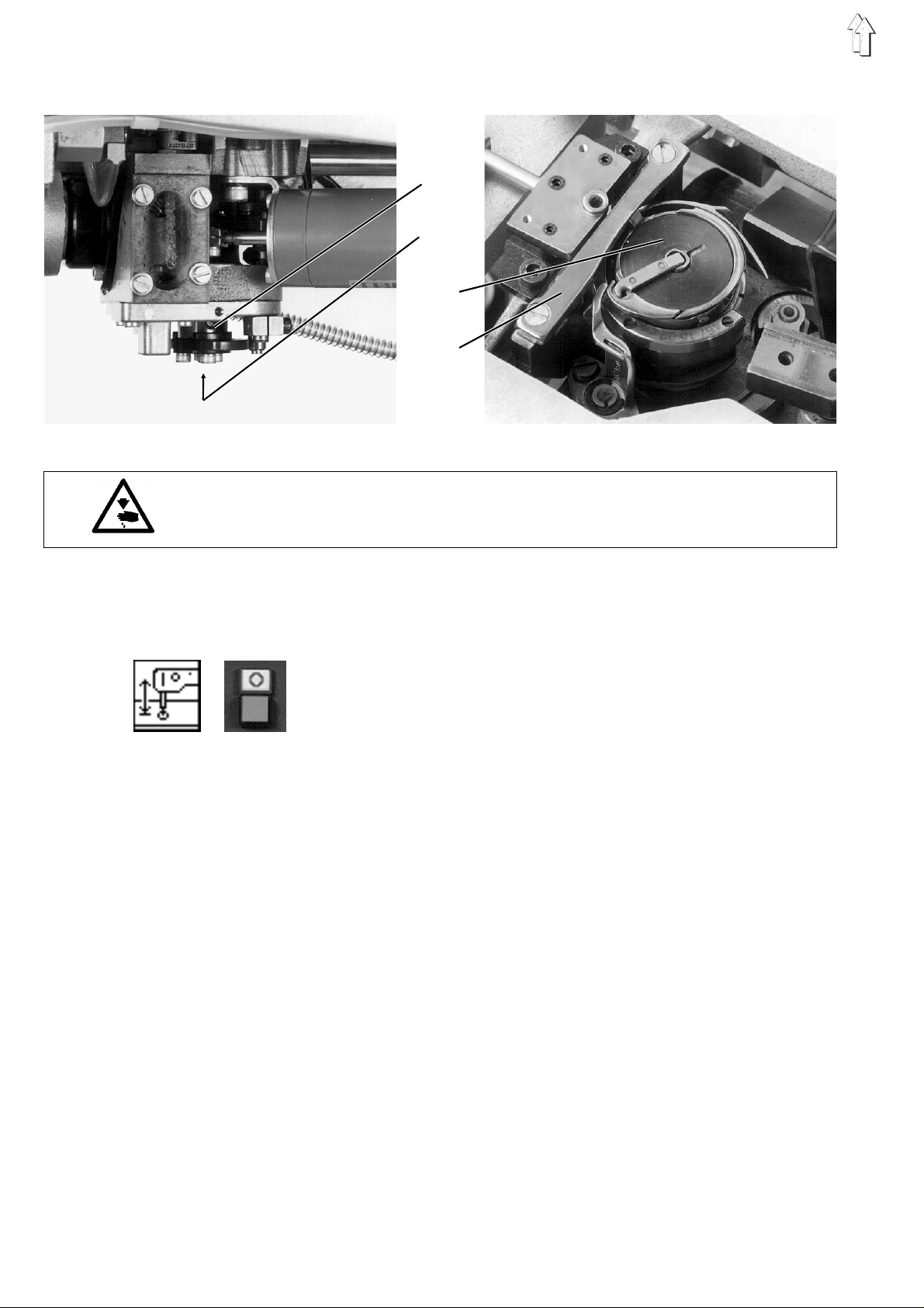
2.10.5 Oil change
1 2 3
Caution: Danger of bodily injuries !
Turn off main switch.
Switch off the ma c hin e before proceedi n g t o the oil change
2.10.6 Topping-up oil
The oil shou ld be changed after t he fi r st 500 service hou rs as f ol l o ws:
–
Remove the oil sump cover.
–
Such the oil. If sucking is impossible,
loosen the dr a i n s cr e w 3 an d l e t the oil flow ou t.
–
Clean the oil sump and the breather tube.
–
Turn-in the drain sc re w 3 af te r ha vi ng r ep l ac e d its gasket.
–
Caution: Danger of bodily injuries !
Turn off main switch.
Turn off the machine before replenish i ng .
Top up if, during the operation of th e m ac h i ne , t he oi l l e vel s t an ds i n
the lower third of the sight glass 2 or when no oil supply can be seen
through the si g ht gl a s s 5 (s . pa ge 26 ) .
Fill "
oil level st ands in the upper third of the sig ht glass.
Other oil brands with the following specifications may be used:
Viscosity at 40°C: 10 mm2/s
Point of inflammation: 150 °C
ESSO SP-NK 10
Pour "
until the oil level stands in the upper third of the oil sight glass.
ESSO SP-NK 10
" oil through the filler neck 6 (s. page 26)
" oil through the filler neck 6 (s. page 26) until the
30
 Loading...