

Page 1

Contents page:
Part 2: Setting-up Instructions, Class 768
1.
Items supplied
2. General and transport packing
3. Assembling the frame
3.1 Assembli ng the frame components . . . . . . . . . . . . . . . . . . . . 5
3.2 Assembling the table plate and fitting it on the frame . . . . . . . . . . 5
3.3 Adjusting the wo rking heig ht . . . . . . . . . . . . . . . . . . . . . . . . 5
4. Fitting the sewing drive
4.1 Drive Packa ges . . . . . . . . . . . . . . . . . . . . . . . . . . . . . . . 7
4.2 Component s of the Drive Packages . . . . . . . . . . . . . . . . . . . . 7
4.3 Mounting the Sewing Drive . . . . . . . . . . . . . . . . . . . . . . . . 7
5. Fitting the upper part of the sewing-machine
5.1 Fitting th e angled support an d fitting the upper part of the sewing machine 9
5.2 F itting the keypad to t he sew ing-machine arm . . . . . . . . . . . . . . 11
5.3 F itting the operating panel . . . . . . . . . . . . . . . . . . . . . . . . . 11
5.4 F itting and tensioning the V-belt . . . . . . . . . . . . . . . . . . . . . . 13
5.5 F itting the pedal . . . . . . . . . . . . . . . . . . . . . . . . . . . . . . . 15
5.5 F itting the knee-switch . . . . . . . . . . . . . . . . . . . . . . . . . . . 15
5.7 Fitting the pneumatic distributor . . . . . . . . . . . . . . . . . . . . . . 15
6. Electrical connection
6.1 General . . . . . . . . . . . . . . . . . . . . . . . . . . . . . . . . . . . 16
6.1 .1 Con necti ons package and grounding kit . . . . . . . . . . . . . . . . . 16
6.2 Ch eck ing the Mai ns Voltage . . . . . . . . . . . . . . . . . . . . . . . . 16
6.3 Connecting the Sewing Drive . . . . . . . . . . . . . . . . . . . . . . . 16
6.4 P otential compensation . . . . . . . . . . . . . . . . . . . . . . . . . . 17
6.5 Connecting the Sewing Light Transformer . . . . . . . . . . . . . . . . 18
6.6 Connection Sockets on the Dr ive Co ntrols DA82GA . . . . . . . . . . . 19
6.7 Mounting the Synchronizer . . . . . . . . . . . . . . . . . . . . . . . . 20
6.8 Connecting the Sewing Machine Head . . . . . . . . . . . . . . . . . . 20
6.9 Direction of Turn of the Sewing Drive . . . . . . . . . . . . . . . . . . . 21
6.9.1 Checking the Direction of Turn . . . . . . . . . . . . . . . . . . . . . . 21
6.9.2 Changing the Direction of Tu rn . . . . . . . . . . . . . . . . . . . . . . 21
6.1 0 Positioning . . . . . . . . . . . . . . . . . . . . . . . . . . . . . . . . . 22
6.11 Set ting Machi ne-specific Parameters . . . . . . . . . . . . . . . . . . 25
6.12 Master Res et . . . . . . . . . . . . . . . . . . . . . . . . . . . . . . . . 29
. . . . . . . . . . . . . . . . . . . . . . . . . . . . . . . 3
. . . . . . . . . . . . . . . . . . . . . 3
GB
7. Pneumatic connection
7.1 Completing the hose connections . . . . . . . . . . . . . . . . . . . . . 31
8. Lubrication
8.1 Topping up with o il . . . . . . . . . . . . . . . . . . . . . . . . . . . . . 33
8.2 Oiling wicks and felts . . . . . . . . . . . . . . . . . . . . . . . . . . . . 34
9. Sewing test
10. Ancillary equipment
10. 1 Sewing la mp . . . . . . . . . . . . . . . . . . . . . . . . . . . . . . . . 37
10. 2 Compressed-a ir maintenance unit . . . . . . . . . . . . . . . . . . . . 41
10. 3 Tape guide . . . . . . . . . . . . . . . . . . . . . . . . . . . . . . . . . 41
Ausg./Edition: 07/99
. . . . . . . . . . . . . . . . . . . . . . . . . . . . . . . . . 35
Page 2
7
B
E
C
8
9
1
10
2
11
12
3
13
14
I
0
4
15
16
5
17
18
6
19
Page 3
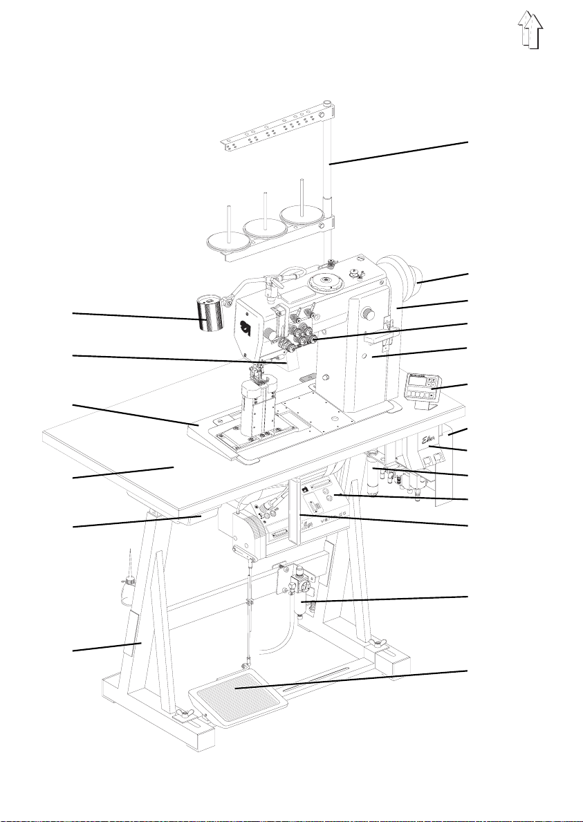
1. Items supplied
What items are
Before setting-up please check that all the required components are present.
This descripti on applies to a sewi ng machine of which
supplied all t he components.
–
–
–
–
–
–
–
–
–
–
–
–
–
–
–
–
–
–
–
–
–
supplied depends on your order
3
8
10
11
12
13
14
15
16
17
18
19
1
2
4
5
6
7
9
sewing lamp with sewing-light transformer (ancillary equipment)
upper-part support
angled supp ort
table plate
drawer
frame
reel stand
proximity switch
belt guard
keypad
upper part of the sewing machine
Efka V810 operating panel
pneumatic distributor
main switch
electro-pneumatic sewing-foot lift (FLP)
Efka DC 1600/DA 82 GA sewing drive
knee-switch
WE-6 filter controller (ancillary equipment)
pedal
belt pulley and V-belt
minor components in the accessory pack
.
DÜRKOPP ADLER AG
has
GB
2. General and transport packing
CAUTION!
The special sewing machine must be set up by trained
specialist pe rsonnel.
Transport packing
If the specia l sewing machine you have bought is already set up, the foll owing transport
packing must be removed:
–
safety straps and battens on the up per part of the mach i ne, table and frame
–
safety block and straps on the sewing drive
3
Page 4
12
3
13
4
5
12
11
I
0
6
7
8
9
10
4
Page 5

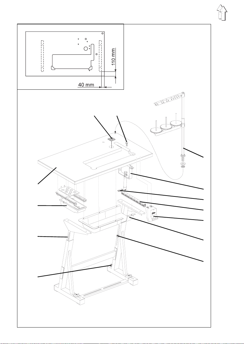
3. Assembling the f rame
3.1 Assembling the frame components
–
Assemble the frame components as shown in the illustration.
–
Adjust set screw 10 so that the frame is stable.
All four of th e frame supports mu st be firmly on the ground!
3.2 Assembling the table plate and fitting it on the frame
–
Screw the
–
Screw the
–
Screw the
–
Screw the
table plate.
–
Attach
washers beneath the table pla t e.
The table plate is factory-fitted with three screw nuts for this purpose.
–
Attach
–
Attach
Its alignment on the frame is indicated by the dimensions in the sketch.
–
Insert
washers.
Fit and align the thread holders and guides.
The thread holders and guides must be vertically in line.
–
Insert
drawer 12
main switch 7
cable conduit 6
holder 5 for the mains-lead cleat
bracket 4
oil collector 8
table plate 13
reel stand 3
stoppers 1 and 2
with its brackets beneath the table plate.
on the right-hand side beneath die table plate.
behind the mai n switch 7 beneath die table plate.
behind the cable conduit 6 under the
with the electro-pneumatic sewing-foot lift (FLP) with screws and
with nails ben eath the table-plate opening.
to the frame with wood screws (8 x 32).
in the hole in the table plate and attach with screws and
in the cable-grommet holes.
GB
3.3 Adjusting the working height
The working height can be adjusted between 750 and 950 mm
(measured to the upper edge of the table plate).
–
Undo screws 9 on both frame spars.
–
Adjust the table plate vertically to the desired working height.
Top prevent til ting, pull the tab l e plate out or it pu sh in by the same dist ance on
both sides.
The scales 11 on the outside of the spars ser ve as adjustment aid s.
–
Tighten both screws 9.
5
Page 6
1
2
3
4
5
6
Page 7

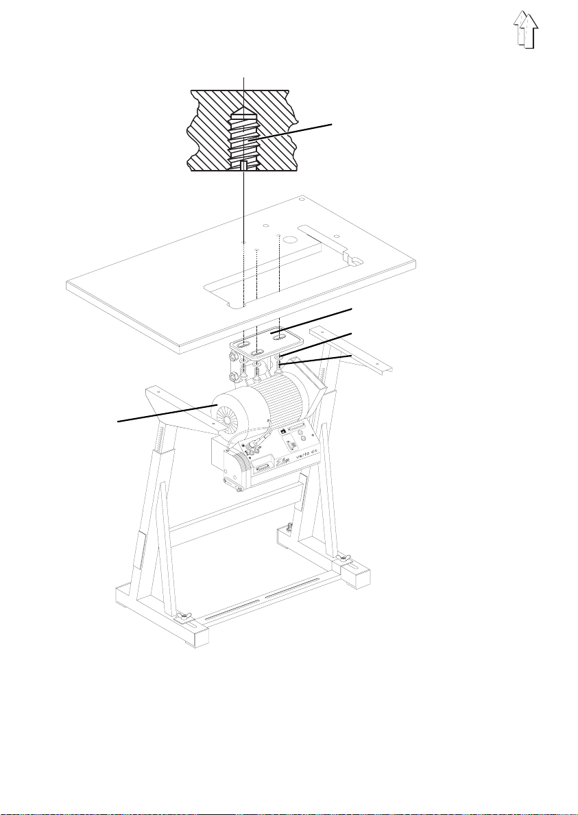
4. Sewing Drives
A direct-current positi oning drive (DC1600/DA82GA) are available f or the classes 768.
4.1 Drive Packages
Class Drive package Sewing drive type Control panel Design voltage
768 9889 07680 1 8 DC1600/DA82GA V810 1x190-240V 50/ 60Hz
4.2 Components of the Drive Packages:
Direct-current positioning drive Clutch coupling positioning drive
DC1600/DA82GA sewing drive
V810 control panel *
Main switch with connection l e ads
Pedal rods
Belt pulley
V-belt
Connection diagram
Mounting material
GB
* The DC1600/DA82GA sewing drive can also be operated with the V820 control panel.
4.3 Mounting the Sewing Drive
–
Mount sewing drive 3 with its base 2 on the underside of the table top.
For this, scre w t he 3 hexagonal screws 6 (M8x35) with washers 5 into the nut s 1 in
the table top.
7
Page 8
1 2 3 4 5 3 7
2
8
1
9
10
8
9
184 mm
4
8
Page 9
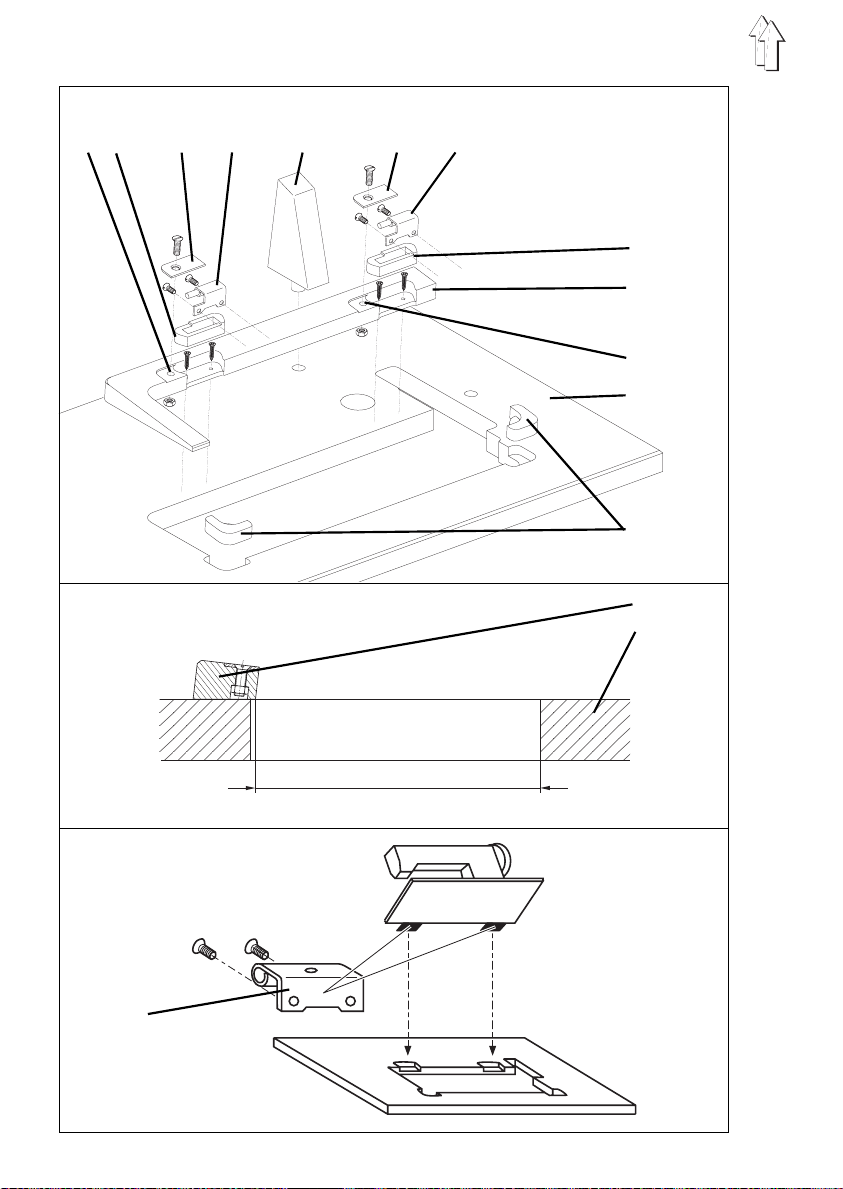
5. Fitting the upper part of the sewing machine
5.1 Fit the angled support and mount the upper part of the
sewing machine
The minor components required to mount the upper part of the sewing machine will be
found in the special sewing machine’s accessory pack.
–
Hammer upper -part support 5 into t he hole in the table pl ate.
–
Insert the (M8) hexagonal nuts from below into t he two holes 1 in th e angled
support 8. Th e f unction of the hex agonal nuts is to se cure the retaining plates 3.
–
Screw the angled support 8 to the table plate 9 with four (5.0x30) chipboard screws
(see sketch).
–
Press the hinge bases 2 into the recesses in the angled support.
–
Press the upper-part supports 10 into the recesses in the table plate 9.
–
Attach hinges 7 with (M6x8) countersunk screws to the base plate of the upper part
of the sewing m achine.
–
Place the upper part of the sewing machine in the opening in the table plate.
The hinges 7 must be in the hinge bases 2.
–
Screw the retaining plates 3 to the angled support 8 with (M8x25) countersunk
screws.
–
Place the oil-return felt of the upper part of the sew i ng machine in the holl ow of the
oil collector.
Caution!
The return hose must not be in contact with any moving parts.
CAUTION!
Do not rotate the upper part of the machine unless the
sewing foot is locked in the up position!
This will damage the sewing-foot lifting mechanism and the
table plate.
GB
9
Page 10
3 4 5
1 2
10
26
7 8 9 10
Page 11

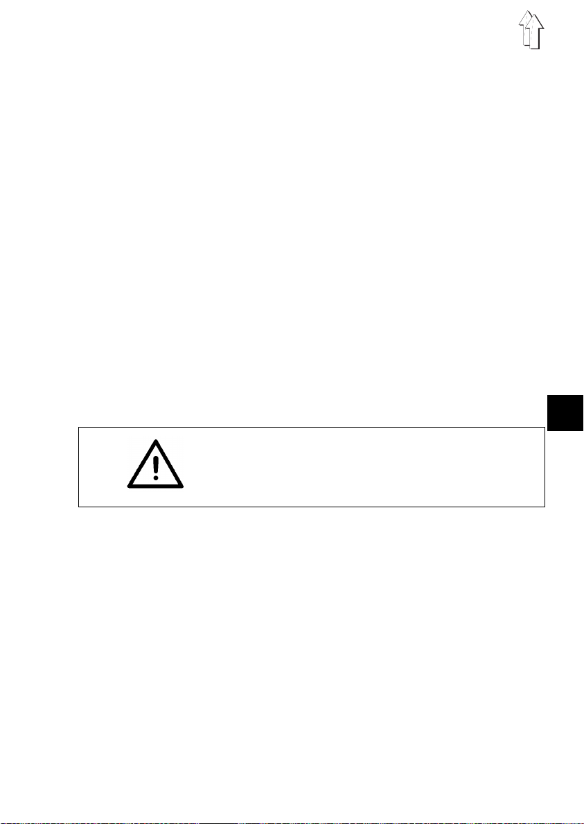
5.2 Fitting the keypad to the sewing-machine arm
The keypad 2 and guard 4 will be found in the special sewing machine’s accessory pack.
There are tapped holes on the operator’s side of t he sewing-machine arm for the
attachment of the keypad 2.
–
Screw the keypad 2 with mounting bracket 4 onto the sewing-machine arm behind
the thread-tensioning plate 1.
–
Lay the connection cable 5 behind the guard 4 and screw t he guard to the rear of
the sewing-machine arm.
–
Pass the connection cable 5 down through the cable-holder on the sewing-machine
pillar.
–
Pass the connection cable 5 down through hole 7 in the table plate.
–
Insert plug 6 of the connecti on-cable 5 into sock et D of the control cabinet.
(See section 6.4)
5.3 Fitting the operating panel
–
Screw the operating panel 10 with bracket 9, screws and washers to the table
plate 8.
–
Pass the connection cable down through hole 7 in the table plate.
–
Insert the connection cable into the cable conduit beneath the table plate at the
side and pass it forwards.
–
Insert the connection-cable plug into socket
(See section 6.6)
of the control cabinet.
b776
GB
11
Page 12
1 2 3
4 5 6 7 8
1 10
12
9 4 8
6 11 12 13
3
14 15 16
Page 13

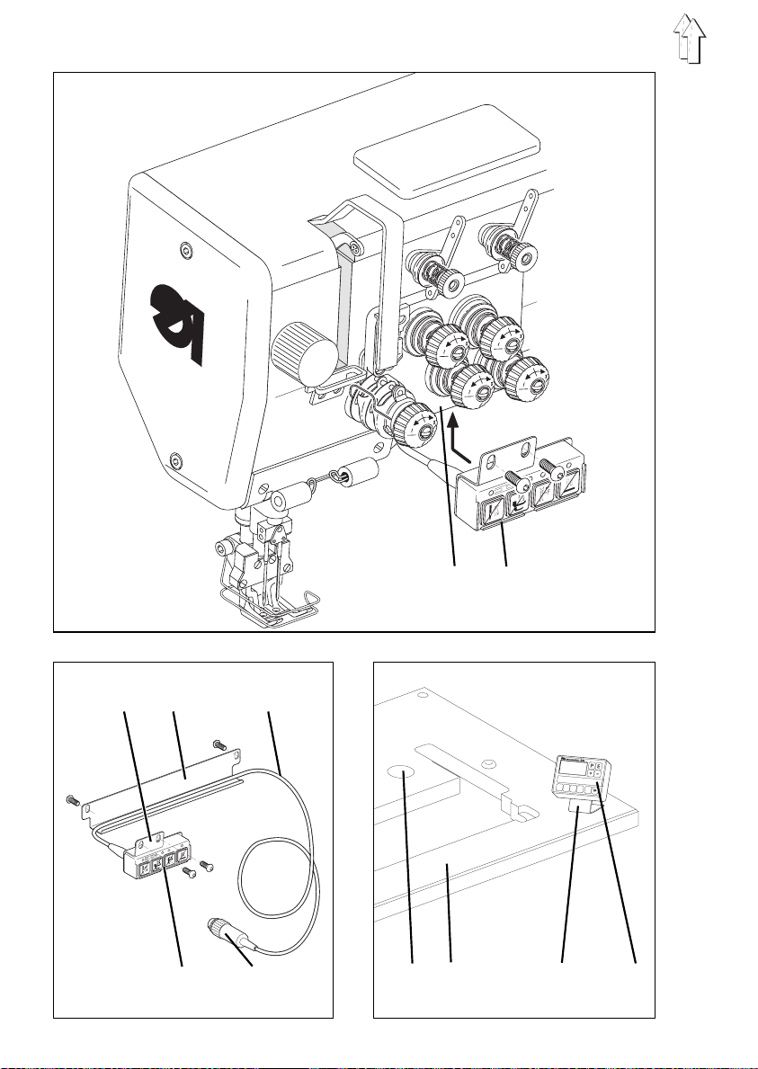
5.4 Fitting and tensioning the V-belt
The V-belt 6, V-belt pulley 2 and sewing-drive belt guard 14 are parts of the drive kit.
Both belt-guard parts 5 and 8, the position holder 4 and the pad 1 will be found in the
special sewi ng machine’s accessory pack.
Removing the guards
If the guards for the V-belt 6 are already in pl ace on delivery, they must be rem ov ed for
the V-belt to be fitted.
–
Unscrew posit i on holder 4.
–
Remove pad 1 after undoing the two screws 10 from the stitch-regulator lever 3.
–
Undo attachment screws of both belt-guard parts 5 and 8.
The screws are a ccessible through the holes in the bel t-guard parts.
–
Remove the rear belt guard 8.
–
Remove front belt guard 5 over stitch-regulator lever 3.
–
Remove the belt-guard cover 14 on the sewing dri ve.
NB:
In the illustration the handwheel 7 has only been removed to improve visibility.
It need not be removed in order to fit the V-belt 6.
Fitting the V-belt and mounting the belt guard on the upper part
–
Attach V-belt pulley 12 to the shaft of the sewing drive 13.
–
Place the V-belt 6 on the belt pulley 2 on the upper part of the sew i ng machine.
–
Pass the V-belt 6 down th rough the opening in t he table plate.
–
Fold back the upper part of the sewing machine.
–
Place the V-belt 6 on the belt pulley 12 of the sewing drive.
–
Return the upper part of the sewing machine to it s original positio n.
–
Fit the two-part belt guard 5 and 8 to the upper part of the sewing machine,
placing the sl it in the front guard 5 over the stitch -regulator lever 3.
–
Attach the pad 1 to the stitch-regulator lever 3 with screws 10.
–
Attach position holder 4 to the rear belt guard 8.
The function of the position holder is to stop the proximity switch 9 from twisting.
GB
Tensioning the V-belt
–
Undo screw 16 on the base of the sewi ng drive 13.
–
Tension the V-belt 6 by swivelling the sewing drive 13.
When the belt i s correctly tensioned It must be possi b l e to depress it by
about 10 mm by gently pressing on it w i th a finger at its mid-point.
–
Tighten screw 16.
Fitting the belt guard to the sewing drive
–
Adjust the a nti-throw protectors 11 and belt-gripping dev i ce 15 of the belt guard 14.
The V-belt 6 must remain on the belt pulleys when the upper part of the sewing
machine is folded back. See the motor manufacturer’s operating manual!
–
Screw on the cover of the belt guard 14.
13
Page 14

1
2
3
4
5
14
6
7
8
Page 15

5.5 Fitting the pedal
–
Attach the pedal 8 to the frame brace 7.
–
Align the pedal 8 laterally as follows:
When the pedal l i nkage 6 is attached it must be vertical .
There are slots i n the frame brace 7 to help align the pedal.
–
Attach the pedal linkage 6 with ball sockets to the pedal 8 and the set-point
generator 4.
–
Slightly undo screw 5.
–
Adjust the height of the pedal linkage 6:
When not under load the pedal 8 must be at an angle of approx. 10°.
–
Tighten screw 5.
5.6 Fitting the knee-switch
The knee-switch 3 (in the accessory pack) is used to activate maximum sewing-foot
stroke during sewing (electro-pneumatic rapid stroke adjustment).
–
Screw the knee-switch 3 beneath the table plate wi th woodscrew.
–
Move the knee-switch 3 sideways until it can be comfortably operated with the right
knee.
–
Insert the plug of the knee-sw itch connection ca bl e into socket b4 of the contro l
cabinet. (See section 6.6)
5.7 Fitting the pneumatic distributor
GB
–
Screw the dis t ri butor 2 with bracket to the right of the frame spar beneath
the table plate.
–
Pass the connection cable from the distributor cabinet on the sewing-machine arm
down through the cable holders on the pillar.
–
Pass the connection cable down through hole 1 in the table plate.
–
Insert the connection-cable plug into the distributor socket.
15
Page 16

6. Electrical connection
6.1 General
NOTE !
All work on the electrical equip m ent of the special sewing
machine may only be conducted by skilled electricians or
appropriately instructed persons.
The mains plug must be pulled out!
It is absolutely necessary to note the Operating
Instructions of the manufacturer, supplied together
with the sewing motor!
6.1.1 Connections package and grounding kit
The electrical connections package and the grounding kit are to be found in the
accessories pack of the special sewing machine.
The electrical connections package contains all part s necessary for th e electrical
connection of the sewing machine head to the sewing drive.
The grounding kit serves for the gr ounding of the sewing m achine head, the knee
switch and the mounting plate of the distributor.
6.2 Checking the Mains Voltage
NOTE !
The design vol t age listed on the rat i ng plate of the sewin g
drive and the mains voltage must agree.
6.3 Connecting the Sewing Drive
The
direct-current positioning drive
By connection with a 3-phase mains of 3 x 380V, 3 x 400V or 3 x 415V the sewing drive
is connected to one phase and the neutral.
By connection with a 3-phase mains of 3 x 200V, 3 x 220V, 3 x 230V or 3 x 240V the
sewing drive is connected to two phases.
When multiple sewing machines are connected to a 3-phase m ai ns, the connections
should be distributed equally among the phases in order to avoid the overburdening of
a phase.
See connection diagram 9800 139001 B
–
Lay the connect i on cable from the mai n switch through the c able duct to the sewing
drive and co nnect to the sewing drive.
–
Lay the mains cable from the main switch through the cable duct and fasten with
the mains lead cleat.
–
Insert the lead from the commutation adjuster into socket b2 of the drive controls.
(Only with a d i rect-current positioning drive) (See section 6.6)
–
Insert the lead from the set-point adjuster into socket
(Only with a d i rect-current positioning drive) (See section 6.6)
16
is operated wi th single-phase-alternating voltage.
of the drive controls.
b80
Page 17

–
The connection to the mains via a plug connection may only occur when all ground
cables (see Chapter 6.4) are attached and the work on the electrical equipment
(e.g. connection of the sewing light transformer, Chapter 6.5) is finished.
NOTE !
The connection of the sewing machi ne to the mains mu st
occur via a plug connection.
6.4 Potential compensation
7
6
GB
1
The grounding kit is found in the accessories pack of the special sewing machine.
The grounding cable conducts static charges from th e sewing machine hea d 6. the
knee switch 2 and the distributor 5 to ground via the sewing drive 1.
–
Attach the grounding cable 7 to the sewing machine head 6 with attachment plug,
flat plug and tooth lock washer at the prepared drilled hole with a screw.
Lead the grou nding cable 7 down through the hole in the t able top.
–
Attach the cable bracket of the grounding cable 4 to the distributor 5 with a screw
and tooth lock washer. Lay grounding cable 4 through the cable duct to the foot of
the sewing drive
–
Attach the cable bracket of the grounding cable 3 to the knee switch 2 with a screw
and tooth lock washer.
Lay grounding cable 3 through the cable duct to the foot of the sewing drive.
–
Attach the cable brackets of the three grounding cables 3, 4 and 7 to the foot of the
sewing drive 1 with a screw (M5) and washer.
2 3 4 5
17
Page 18

6.5 Connecting the Sewing Light Transformer (Optional Equipment)
1
–
Pull the sewing machine mains plug out!
–
Lay the mains connection cable of the sewing light t ransformer 1 through the cable
duct 2 to the main switch 3.
–
The connecti on occurs on the mains input side of the main switch.
(See connection diagram 9800 1390 01 B)
NOTE !
The sewing light transformer is connected directly to the
mains and is still under current when the main switch is
switched off.
Work on the sewing light transfo rm er, e.g. replacing the
fuse, is only to be conducted with the mains plug pulled.
2 3
18
Page 19

6.6 Connection Sockets on the Drive Controls DA82GA
GB
19
Page 20
2
3
1
4 5 6 7
6.7 Mounting the Synchronizer
–
Place the synchronizer 3 on the ha ndwheel flange.
The groove 6 on the housing of the synchronizer must lock over the twist barrier 5
on the belt guard.
–
Tighten both set scr ews 2 on the synchronizer ring 4.
–
Guide lead 7 of the synchronizer down t hrough the cutout in the table top
–
Faire passer le câble de raccordeme nt du transmetteur de position latéralement
dans la cond ui te de câbles sous la tablette et le poser vers l’avant.
–
Insert the plug of the synchronizer into the socket b1 of the drive controls.
(See section 6.6)
6.8 Connecting the Sewing Machine Head
The electrical connection to the sewing machine head occurs via the central plug
connection 1.
–
Insert the plug (16-pin) of the connection lead into the socket of the sewing
machine head.
–
Guide the connection lead down through the cutout in the table top.
–
Insert the plug (37-pin) into the socket A of the drive controls.
(See section 6.6)
20
Page 21

6.9 Direction of Turn o f the Sewing Drive
NOTE !
Before commissioning the special sewing machine it is
essential to check the direction of t urn of the sewing dri ve.
The operation of the special sewing m achine with an
incorrect direction of turn can lead to damage.
The illustration shows the normal direction of turn of the sewing drive.
(Counterclockwise rotation = Counterclockwise when viewing the belt pulley)
6.9.1 Checking the Direction of T urn with a DC1600/DA82GA Direct-current
The direction of turn of the direct-current positioning drive is set to counterclockwise
rotation via the factory setting of the preset value (= 1) of the parameter F-161.
However, the first action during com missioning must be to check the di rection of turn.
For this proceed e.g. as follows:
–
–
–
–
–
–
Positioning Drive.
The synchronizer must be mounted. See Chapter 6.7
The plugs of the set-point adjuster, commutation adjuster, synchronizer and control
panel must be i nserted. See pictu re 6.6
Do not insert the 37-pin plug of the sewing machine head.
Turn the main switch on.
The control panel shows "Info A5" , this means that no valid autoselect resistor was
found and th e m aximum speed is thus limited.
Press the pedal forward slightly; the drive turns; check the direction of turn.
Insert the 37-pin plug of the sewing machine head again.
GB
6.9.2 Changing the Direction of Turn with a DC1600/DA82GA Direct-current
If the sewing drive runs with an incorrect direction of turn, the parameter
"Technician Level" must be set to the value 1.
With V810 cont rol panel see Chapter 6.11.4
With V820 cont rol panel see Chapter 6.11.5
Positioning Drive.
of the
F-161
NOTE !
After a change in the direction of turn the posit i ons must be
reset. See Chapter 6.10
21
Page 22

6.10 Positioning
6.10.1 Definition of the Positions
Reference position
The reference position is the initial position for all further positions. It is defined as the
needle position in which the needle point, with lowered needle in normal direction of
turn, lies at the level of the top of the needle plate. After a removal of the synchro ni zer
only the reference position must be reset, all further positions, with correctly set
controls, are then automatically correct again.
Position 1
In the 1st Position the lower edge of the needle eye of the lowering needle 1 in the
normal direction of turn lies at the same height as the hook cover ring 2.
Position 1A
This position is only required for internal functions of the controls, it should lie at least
60 increments after position 1.
Position 2
In the 2nd position the needle bar lies at the upper de ad center.
Position 2A
This position is only required for internal functions of the controls, it should lie at least
60 increments after position 2.
Position 3
This position is not required for the classe 768.
Position 3A
This position is not required for the classe 768.
6.10.2 Setting Positions with a DC1600/DA82GA Direct-current Positioning Drive
6.10.2.1 General
The digital sy nc hronizer sends the controls 512 impulses (increments) and an
additional impulse once per revolution. All needle positions are determined by these
impulses and by the values of the parame t ers F-170 and F-171.
No mechanical settings are required on the synchronizer.
Attention!
After the following work
1. First operation of the sewing drive.
2. Repla cement of the sewing drive, the drive controls or the cont rol plate of the
drive control s.
3. Repla cement of the EPROMs in the drive controls.
After the following work only
1. Removal and mounting or replacement of the synchronizer.
all positions
the reference position
must be
reset
.
must be
reset.
22
Page 23

6.10.2.2 Setting Positions with the V810 Control Panel
Entry of the code number for the technician level
–
Turn the main switch off.
–
All plugs on the controls of the sew i ng drive must be plugged in.
–
Press the "P" key and hold pressed.
–
Turn the main switch on. The disp l ay shows "
–
Release the "P" key
–
Enter code no.
changed. The next number is called up with the ">>>>" key.
–
Press the "E" key. The first parameter,
Setting the reference position
–
After entry of the code number press the "E" key.
The first parameter,
–
With the "+", "-" and ">>>>" keys set the parameter
–
Press the "E" key. Shown in the display = "
–
Press the ">>" key. Shown in the display = "
–
Turn the handwh eel in the normal di rection of turn unt i l the character "
disappears from the display, then turn farther until the reference position (needle
point, with lo wered needle, at th e l evel of the top of t he needle plate) is re ac hed.
–
Press the "E" key. The reference posit i on is saved. Shown in the di splay "
–
If the refe rence position was not saved, an error m essage appears in t he display =
"
above.
Setting positions 1 and 2
–
The reference position is set. (see above)
–
Enter parameter
–
Press the "E" key. Shown in the display = "
–
Press the ">>" key. Shown in the display = "
–
If necessary, correct parameter value *. Either with the "+" and "-" keys or by
turning the handwheel.
–
Press the "E" key. Shown in the display = "
–
If necessary, correct parameter value *. Either with the "+" and "-" keys or by
turning the handwheel.
–
Press the "E" key. Shown in the display = "
–
If necessary, correct parameter value *. Either with the "+" and "-" keys or by
turning the handwheel.
–
Press the "E" key. Shown in the display = "
–
If necessary, correct parameter value *. Either with the "+" and "-" keys or by
turning the handwheel.
–
Press the "P" key twice. The set t i ngs are completed, the programming level is
exited
–
Check the positions. See Chapter 6.10.2.4
". Turn the handwheel farther, press the "E" key and repea t the procedure
inF E3
. With the "+" and "-" keys, the value of the blinking number is
1907
F-100
, at the tech nician level is shown.
F-100
Sr1
PoS0 ( )
.
F-171
Sr2
1 xxx"
2 xxx
1A xxx
2A xxx
"
C-0000
, at the technician level is shown.
.
F-170
"
"
( )
"
= parameter value of pos. 1.
" = parameter v alue of pos. 2
" = parameter value of pos. 1A
" = parameter value of pos. 2A
"
F- 171
"
GB
* Attention!
the parameter sheet (acc essories pack).
The parameter values for the positions 1, 2, 1A and 2A are to be found on
23
Page 24

6.10.2.3 Setting Positions with the V820 Control Panel
Entry of the code number for the technician level
–
Turn the main switch off.
–
All plugs on the controls of the sewing drive must be plugged in.
–
Press the "P" key and hold pressed.
–
Turn the main switch on. The display shows "
–
Release the "P" key
–
Enter code no. 1907 with the numeric keys 0 to 9.
–
Press the "E" key. The first parameter ,
number blinks.
Setting the reference position
–
After entry of the code number press the "E" key .
The first parameter,
–
Set the parameter
–
Press the "E" key. Shown in the display = "
–
Press the "B" key. Shown in the display = "
–
Turn the handwheel in the normal direction of turn until the character "( )" di sappears from
the display, then turn farther until the reference position (needle point, with lowered needle,
at the level of the top of the needle plate) is reached.
–
Press the "E" key. The reference posi tion is saved. Shown in the di splay "
–
If the reference position was not saved, an error message appears in the display = "
". Turn the handwheel repeatedly until the desired reference position is reached.
E3
Setting positions 1 and 2
–
The reference position is set. (see above)
–
Enter parameter "
–
Press the "E" key . Shown in the display = "
–
Press the "B" key. Shown in the display = "
–
If necessary, correct parameter value *. Either with the "+" and "-" keys or by turning the
handwheel.
–
Press the "E" key. Shown in the display = "
–
If necessary, correct parameter value *. Either with the "+" and "-" keys or by turning the
handwheel.
–
Press the "E" key. Shown in the display = "F 171 1A xxx" = parameter value of pos. 1A
–
If necessary, correct parameter value *. Either with the "+" and "-" keys or by turning the
handwheel.
–
Press the "E" key. Shown in the display = "F 171 2A xxx" = parameter value of pos. 2A
–
If necessary, correct parameter value *. Either with the "+" and "-" keys or by turning the
handwheel.
–
Press the "P" key twice. The settings are completed, the programming level is exited
–
Check the positions. See Chapter 6.10.2.4
, at the technician level is shown.
F-100
with the keys 0 to 9.
F-170
".
F-171
F-100
F-170 Sr1
F-170 PoS 0 ( )
Sr2
F 171 1 xxx
F 171 2 xxx
"
C-0000
, at the technician level is shown and the first
"
"
"
F- 171
"
" = parameter value of pos. 1
" = parameter value of pos. 2
inF
* Attention!
the parameter sheet (accessor ies pack).
The parameter values for the positions 1, 2, 1A and 2A are to be found on
24
Page 25

6.10.2.4 Checking Positioning
Position 1
–
Turn the main switch on
–
Press the peda l briefly forward and rel ease again. The needl e positions in
position 1.
–
Check the position of the needle.
Position 2
–
Press the pedal briefly forward and then step back on it and hold down until the
machine stop s. The needle positions in position 2.
–
Check the position of the needle
If one or both needle positions do not agree with the definitions in Chapter 6.10.1, then
a correction of the setting is to be conducted as per Chapter 6.10.2 or 6.10.3.
6.11 Setting Machine-specific Parameters
6.11.1 General
The functions of the controls of the sewing drive are determined by the program and the
setting of the parameters.
At delivery of the sewing drives the parameter values have been preset by Efka (preset
values). For each class and subclass some parameters at the "Technician" and the
"Supplier Level" must be altere d in order to optima l l y adapt the control s to the machine.
The affected parameters are listed in the table below and in the parameter sheet (in the
accessories pack).
GB
6.11.2 Autoselect
The controls "recognize" by measuring the autoselect resistor, which is found in the
machine, which machine series they are connected to. Control functi ons and the preset
values of the parameters are selected through autoselect. If the controls recognize no
or an invalid autoselect resistor, then the drive only runs with the so-called emergency
operation functions in order to protect the mach i n e from damage.
See "EFKA DA82GA 3301" operating instructions
Autoselect Classes Controls Parameter sheet
resistor Sewing drive
1000R (1000 Ohm) 768 DA82GA 9800 130014 PB51
25
Page 26

6.11.3 Table of the Machine-specific Parameters of t he DA82GA Con trols
The values of the parameters listed i n the following must be changed from the preset
value.
The values (x) to be set are to be found in t he parameter sheet 9800 130014 PB51
(In the accessories pack of the machine).
Parameters * Designation 768
F-111 T Upper limit of the maximum speed x
F-117 T High lift walking speed x
F-147 T Functions of the pushbutton on D.3 x
F-171 T Position 2 x
F-196 T Function of both thread tension release x
F-197 T Function of 2.thread tension with x
F-225 A Speed regula t i on, x
* T = Parameters at the technician level, A = Parameters at the supplier level
Position 2A x
with presser foot lifting
HP and Speedomat
0 = machine normal, 1 = machine middle heavy
NOTE !
The altering of the parameter values must be conducted
very carefully because the machine can be damaged
through incorrectly set drive controls! All parameter values
can be reset to the delivery stat us (preset values) by a
master reset. See Chapter 6.12
26
Page 27

6.11.4 Setting Par am et er Values with the Control Panel V810
Changing parameter values at the "Technician Level"
Entry of the code number for the technician level
–
Turn the main switch off.
–
All plugs on the controls of the sewing drive must be plugged in.
–
Press the "P" key and hold pressed.
–
Turn the main switch on. The display shows "
–
Release the "P" key
–
Enter code no.
The next number is called up with the ">>" key .
–
Press the "E" key. The first parameter ,
Selecting the parameters and changing the values
–
The next or the previous parameter is selected with the "+"and "-" keys.
–
The parameter can be entered directly with the ">>", "+",and "-" keys.
–
Press the "E" key. The value of the selected parameter is shown.
–
The parameter value can be altered with the "+" and "-" keys.
–
Press the "E" key. The next parameter is shown.
or press the "P" key - the same parameter is shown.
Saving changed parameter values
–
Press the "P" key, programming is ended.
–
Sew a complete seam, that is, step the pedal forward and then completely back.
The change is sav ed.
–
If no seam is sewn, the change is lost.
–
Through renewed pressing of the "P" key one returns to the progra m ming level.
. With the "+" and "-" keys the value of the blinking number is changed.
1907
F-100
"
C-0000
, at the technician level is shown.
GB
Changing parameter values at the "Supplier Level"
Entry of the code number for the supplier level
–
Turn the main switch off.
–
All plugs on the controls of the sew i ng drive must be plugged in.
–
Press the "P" key and hold pressed.
–
Turn the main switch on. The disp l ay shows "
–
Release the "P" key
–
Enter code no.
changed. The n ext number is called up wi th the ">>" key.
–
Press the "E" key. The first parameter,
–
Proceed as in "
. With the "+" and "-" keys the value of the blinking number is
3112
F-200
Selecting the Parameters and Changing the Values
NOTE !
The altered parameter values are only then saved, when,
after exiting the programming level, a complete seam is
sewn, that is, step the pedal forward and then completely
back. If, after exiting the programming level, the drive is
immediately turned off the chan ges are lost.
"
C-0000
, at the supplier level is shown.
"
27
Page 28

6.11.5 Setting Para me te r Values with the V820 Control Panel
Changing parameter values at the "Technician Level"
Entry of the code number for the technician level
–
Turn the main switch off.
–
All plugs on the controls of the sewing drive must be plugged in.
–
Press the "P" key and hold pressed.
–
Turn the main switch on. The display shows "
–
Release the "P" key
–
Enter code no.
–
Press the "E" key. The first parameter ,
number blinks.
Selecting the parameters and changing the values
–
After entry of the code number the first parameter,
The first number of the parameter number blinks.
–
Enter the desired parameter number with the numeric keys 0 to 9.
–
Press the "E" key. The val ue of the selected parameter is shown.
–
The parameter value can be changed with the "+" and "-" keys.
–
Press the "E" key. The next parameter is shown
or press the "P" key - the same parameter is shown.
Saving changed parameter values
–
Press the "P" key, programming is ended.
–
Sew a complete seam, that is, step the pedal forward and then completely back.
The change is saved.
–
If no seam is sewn the change is l ost.
–
Through renewed pressing of the "P" key one returns to the programming level.
with the numeric keys 0 to 9.
1907
F-100
"
C-0000
, at the technician level is shown and the first
, is shown.
F-100
Changing parameter values at the "Supplier Level"
Entry of the code number for the supplier level
–
Turn the main switch off.
–
All plugs on the controls of the sewing drive must be plugged in.
–
Press the "P" key and hold pressed.
–
Turn the main switch on. The display shows "
–
Release the "P" key
–
Enter code no .
–
Press the "E" key. The first parameter,
–
Proceed as in "
with the numeric keys 0 to 9.
3112
Selecting the Parameters and Changing the Values
NOTE !
The altered parameter values are o nl y then saved, when,
after exiting the programming level, a complete seam is
sewn, that is, step the pedal forward and then completely
back. If, after exiting the programming level, the drive is
immediately turned off the changes are lost.
F-200
"
C-0000
, at the supplier level is shown.
28
"
Page 29

6.12 Master Reset
All parameter values are returned to their delivery status (preset values) through a
master reset.
Note
During a master reset all external consumers, e.g. sewing foot lift, must be turned off.
For this reason the 37-pin plug "A" of the machine connection should be unplugged
from the drive controls.
–
Turn the main switch off.
–
Unplug 37-pi n plug "A" from the drive controls. (See section 6.6)
–
Press the "P" key and turn the main switch on.
–
Release the "P" key.
–
Enter code number "
–
Press the "E" key. The parameter
–
Press the "E" key. The value of the parameter
–
Set the value to
–
Press the "P" key twice.
–
Turn the main switch off.
–
Insert 37-pin plug "A". (See section 6.6)
–
Turn the main switch on after a brief wait. All parameters, except 111, 161, 170,
171 and 190 to 193, have the preset values that were set at the factory again.
170
". See Chapter 6.10.2.2 and/or 6.10.2.3
1907
is shown.
F-100
F-100
.
is shown.
GB
NOTE !
With a master reset certain parameters, such as e.g.
(reference position),
(motor direction of turn) are not reset.All parameters which
are set specifically for the machine must be set again as
per the Parameter Sheet.See Chapter 6.11
(needle position) and
F-171
F-170
F-161
29
Page 30

1
2
3
4
5
30
Page 31
7. Pneumatic connection
7.1 Completing the hose connections
The
class 768
equipment:
–
electro-pneumatic sewing-foot lift (FLP)
–
electro-pneumatic rapid stroke-adjustment system (HP)
For the operation of this pneumatic equipment the spec i al sewing machine must b e
supplied with absolutely dry compressed air.
Connecting the electro-pneumatic sewing-foot lift (FLP)
–
Complete the PU hose connection between throttle valve 1 and the cylinder 3.
Connecting the electro-pneumatic rapid stroke-adjustment system (HP)
–
Complete the PU hose connection from throttle valve 2 to the distributor cabinet at
the rear of th e sewing-machine arm.
Compressed-air connection
–
Complete t he PU hose connection between compressed-air connector 4 on the
frame 5 and th e solenoid valve.
–
Connect the pneumatic units to the factory compressed-air supply with the
connection hose (Ø = 9 mm).
Pneumatic connection kit
A pneumatic connection kit for frames wi th compressed air-maintenance units and
pneumatic ancillary equipment is available under order no. 797 3031.
It contains the following ite m s: - conn ection hose, 5m long, Ø = 9 mm
pillar sewing machine is fitted as standard with the following pneumatic
CAUTION!
The pneumatic units are only guarant eed to function
properly if th e supply pressure is between 8 and 10 bar.
The operating pressure of the speci al s ewing machine
is
.
6 bar
- hose nozzle s and hose ties
- plug-and-socket connector
GB
31
Page 32

1
B
E
C
2
32
3 4
Page 33

8. Lubrication
Caution - danger of injury!
Oil can cause skin eruptions.
Avoid protracted contact with the skin.
In the event o f contact, thoroughl y wash the affected area .
CAUTION!
The handling an d disposal of mineral oi l s is subject to legal
regulation.
Deliver used oil to an authorised collection point.
Protect your environment.
Take care not to spill oil.
To top up the oi l reservoir use only
or an equivalent oil of the followi ng specification:
–
viscosity at 40° C : 10 mm2/s
–
flashpoint: 150 °C
ESSO SP-NK 1 0
following part numbers:
2-litre container: 9047 000013
5-litre container: 9047 000014
is available from
ESSO SP-NK 1 0
DÜRKOPP AD LER AG
lubricating oil
retail outlets under the
8.1 Topping up with oil
Lubricating the head and lower part of the sewing-machine
–
Top up with oil through the hole beneath stopper 1.
–
Check oil level at the sight gla ss 2.
The oil level mus t be above the red
–
Screw stopper 1 (in the accessory pack) into the hole i n t he arm cover.
–
Remove any oil spillage from the oil collector.
Shuttle lubrication
–
Use the oil can (in the accessory pack) to drip a few drops of oil into hole 3 in the
shuttle plunger ring 4.
CAUTION!
In order to ens ure that the shuttle i s properly lubricated
during the running-in period, a relatively larg e quantity of
oil is set prior to despatch.
This setting should be checked, and after the running-in
period reduced to the required quantity (see servicing
instructions).
"full"
line.
GB
33
Page 34

8.2 Oiling wicks and felts
1
5
6
2 3
When the machi ne is set up and after long periods of disuse the wicks and felt 1 in the
head must be soaked with a little oil.
–
Unscrew hea d cover 2.
–
Soak wicks and fe l t 1 with a little oil.
–
Replace and screw down the head cover 2.
The felt tab 3 of the head cover must be clamped between the absorption felt 6
and the nipple of the wick 5.
The foil 4 must be in contact with the inside of the head cover 2.
34
4
Page 35

9. Sewing test
B
C
When setting- u p is complete a sewing test must be carr i e d out.
–
Insert the mains plug.
Caution - danger of injury!
Turn off the main switch.
The looper thread for spooling may only be threaded with
the sewing machine switched off.
–
Thread the looper thread ready for spooling (see operating manual).
–
Lock the sewing feet in the up position (see operating manual).
–
Turn on the main switch and fill the bobbin at low speed.
Caution - danger of injury!
Turn off the main switch.
The needle thread and looper threa d m ay only be threaded
with the sewing machine switched off.
E
1
GB
–
Thread the needle thread and looper thread (see operating manual).
–
Select the material to be processed.
–
Start the sewing test at low speed, then gradually increase i t.
–
Check whethe r the seams are satisfactory.
If not, alter the thread tension (see operating manual). If necessary also check the
settings given in the servici ng instructions and correct them if appropriate.
–
While the sewing machin e
the viewing w i ndow 1. If no oil fl ow is visible at the vi ewing window durin g
operation, c heck the recirculati on lubrication (see servicing instructions).
is running check t he oil supply to the sew i ng head at
35
Page 36

2
3
4
8
5
6
7
1
9
36
10
11
12
13
14
Page 37

10. Ancillary equipment
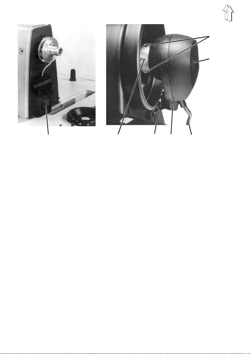
10.1 Sewing lamp
Fitting the sewing lamp
Two sewing lamps are available as ancillary equipment for the
Fitting the halogen sewing lamp
A special fitment (order no. 0907 487519) is required for the halogen sewing lamp 1.
–
Unscrew arm cover 6.
–
Attach holder 5 with serrated lock washer 7 and screw 8 to the arm cover 6.
There is a tapped hole in the arm cover for this purpose.
–
Replace the a rm cover 6.
–
Place the halo gen sewing lamp 1 on th e holder 5 and align.
–
Tighten locking screws 2 and 3.
–
Stick the cable-holder 4 to the rear of the sewing -machine arm.
Fitting the light-guide sewing lamp
A special fitment (order no. 9880 767001) is required for the light-guide sewing lamp 9.
–
Screw the light-guide sewing lamp 9 onto mounting plate 10 with countersunk
screws.
–
Attach the mounting plate 10 with countersunk screws to the rear of the
sewing-machine arm. There are tapped holes in the sewing-machine arm for this
purpose.
–
Screw the holder 11 for the light-guide 13 onto the head cover 12.
–
Screw the ligh t -guide 13 with clamp 14 to the sewing-machi ne head.
class 768
.
GB
37
Page 38
4
I
0
1 2
38
3
Page 39

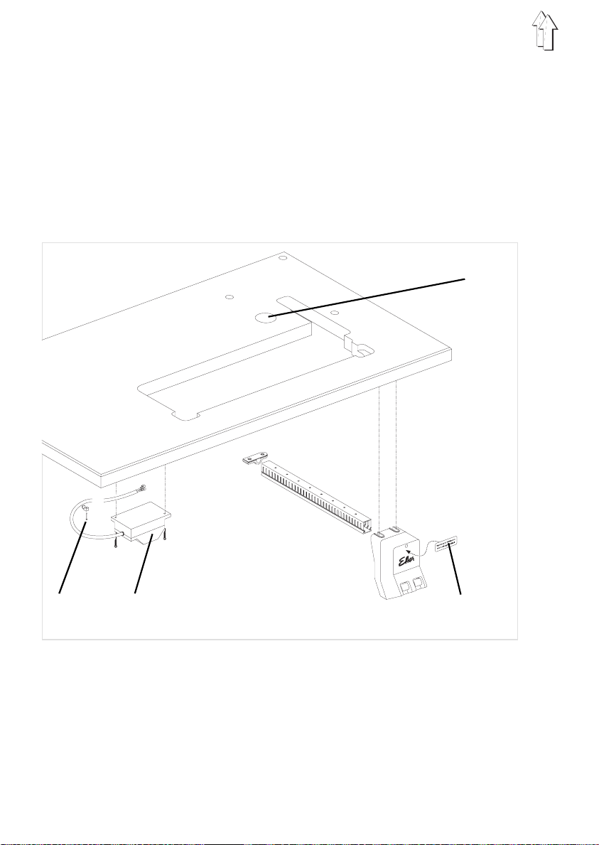
Fitting the sewing-light transformer
Power for the sewing lamps is supplied by the sewing-light transformer which is
available as ancillary equipment (order no. 0798 500088).
–
Attach the sewing-light transformer 2 beneath the table plate with chipboard
screws 1.
–
Attach the connection cable beneath the table plate with cable ties.
Connecting the sewing lamp
CAUTION!
Turning off the main switch does not turn off the power
supply to the sewing lamp.
–
Stick the adhesive label 3 with safety warning to the front of the main switch.
–
Pass the sewing-lamp connection cable behind the guard on the sewing-machine
arm.
–
Pass the connection cable down through the cable-holders on the pillar.
–
Pass the connection cable down through hole 4 in the table plate.
–
Plug the cable into the sewing-light transformer.
GB
39
Page 40

40
12 3 4
6
4
8
2
10
5
6
7
Page 41

10.2 Compressed-air main tenance unit
The WE-6 filter controller for pneumatic ancillary equipment is available under
order no. 9781 000002.
Connecting the compressed-air maintenance unit
–
Attach the compressed-air maintenance unit 4 with bracket 3 and link plate 2 to the
frame brace 1.
–
Connect the compressed-air ma intenance unit to t he works compressed -air supply
with connect i on hose 5 (Ø = 9 mm) and R 1 / 4" hose connector.
Adjusting the operating pressure
The operating pressure is
It can be read off at the manometer 7.
–
To adjust the operating pressure pull out and rotate the handle 6:
clockwise = to increase pressure
anti- clockwi se = to decrease pressure .
6 bar
.
10.3 Tape guide
Fitting the tape-roll holders
–
Attach the holder 1 with 4 screws beneath the table plate. Care must be taken that
the centre o f the tape on the tape-roll holder co i n cides with the cent re of the seam.
1
GB
41
Page 42

Fitting the tape guide
–
Fit the synthetic guide 1 and guide 2.
–
Fit the screw 3, guide 2 and washer 4. Do not fully tighten screw 3.
–
Attach the synthetic guide 1, guide 2, screw 3 and washer 4 to the sewing-machine
pillar with the screw 5.
–
Attach the lower tape guide 6 to the sewing-machine pillar with washers 7 and
screws 8.
–
Align the catch of the guide 2 to the centre of the seam and secure with screw 3
and washer 4. Then tighten screw 5.
2
1
42
4
3
5
6
7
8
 Loading...