

Manual, complete
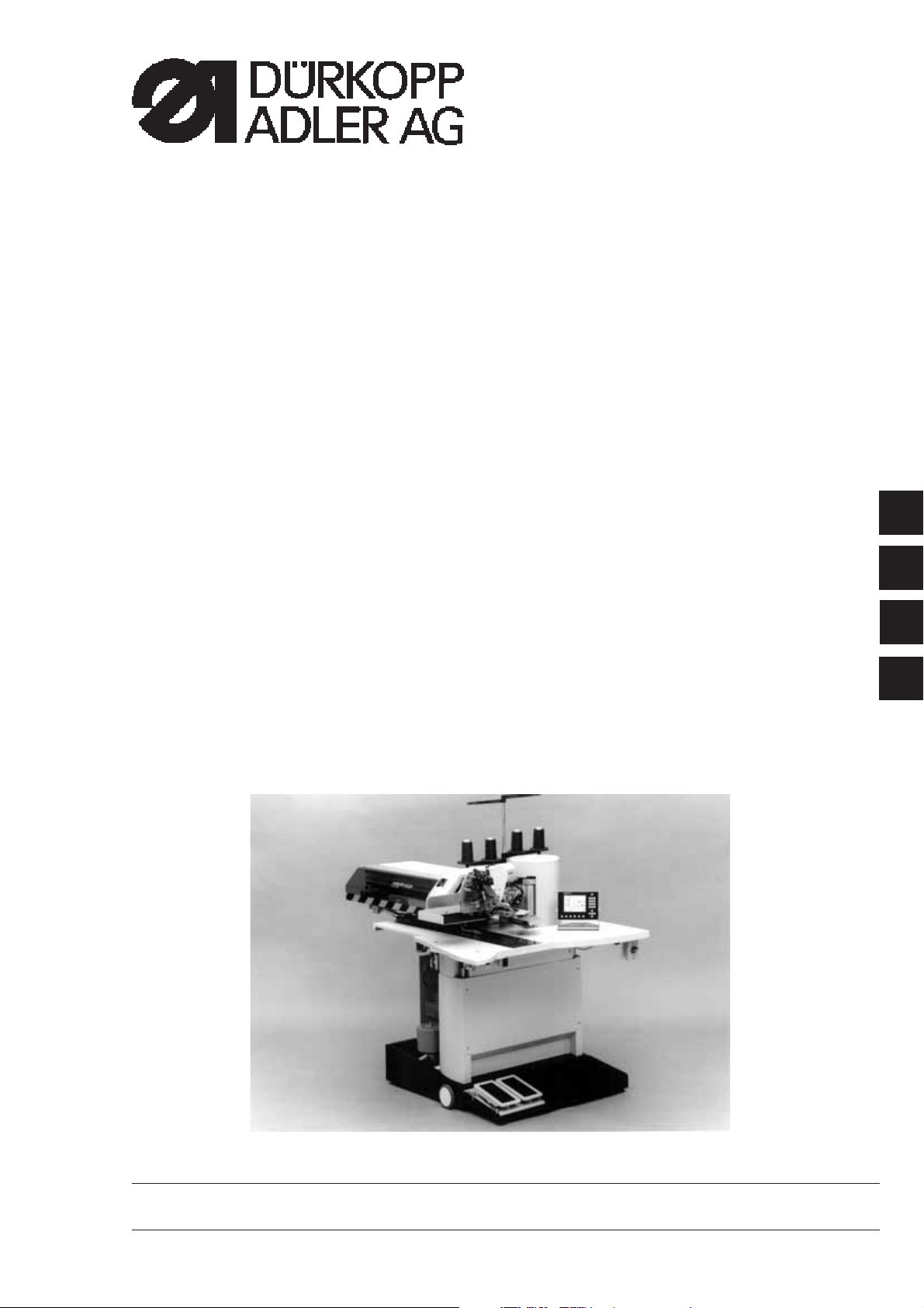
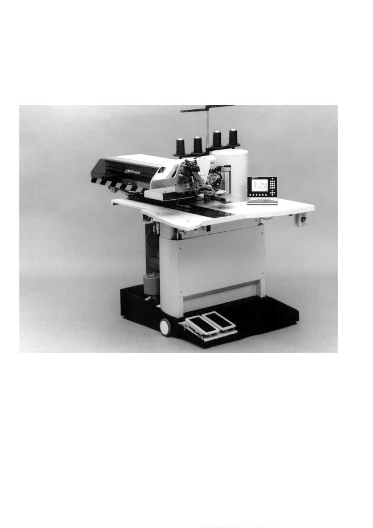
745-34
Sewing unit for runstitching of piped flap
and welt pocket openings and pocket corners
Working methods: A, B, D, F
Operating Instructions
Installation Instructions
Service Instructions
Instructions for Programming DAC
1
2
3
4
Postfach 17 03 51, D-33703 Bielefeld • Potsdamer Straße 190, D-33719 Bielefeld
Telefon + 49 (0) 5 21 / 9 25-00 • Telefax + 49 (0) 5 21 / 9 25 24 35 • www.duerkopp-adler.com
Ausgabe / Edition: 01/2004 Printed in Federal Republic of Germany Teile-Nr./Part.-No.: 0791 745161

745 - 34
Manual, complete
Summary
Operating Instructions
Installation Instructions
Service Instructions
Instructions for Programming DAC
Interconnection-diagram
9870 745100 B
9870 745115 B
9870 745116 B
9870 001018 B
Pneumatic circuit plan
9770 745003

Index Page:
Part 2: Installation Instructions 745-34
1. Scope of delivery .............................................. 3
2. General notes ................................................ 3
3. Installing the sewing unit
3.1 Transport ................................................... 4
3.2 Removing the security devices ...................................... 5
3.3 Setting the working height ......................................... 6
3.4 Adjusting the foot pedals .......................................... 7
4. Attaching the machine parts removed for shipping
4.1 Thread reel holder .............................................. 8
4.2 Cylinder for pick-up folder stroke ..................................... 9
4.3 Workpiece boxes .............................................. 10
4.4 Fastening the holder for control panel, bobbin winder and right-hand tray............. 11
4.5 Table extension (optional equipment) .................................. 12
4.5.1 Table extension for working method with bundle clamp carriage .................. 12
4.5.2 Table extension for stacking to the side for 745-34 A and 745-34 D ................ 13
4.6 Throw-over stacker (optional equipment) ................................ 14
5. Electrical connection
5.1 Connecting the control panel DAC II C .................................. 16
5.2 Connecting the external bobbin winder ................................. 16
5.3 Making the mains connection ....................................... 16
5.4 Checking the nominal voltage ....................................... 17
5.5 Checking the nominal voltage of the vacuum device (optional equipment) ............ 18
5.6 Direction of rotation of the sewing motor ................................ 18
6. Pneumatic connection .......................................... 19
7. Connection to the factory-own vacuum unit ............................. 20
8. Oil lubrication................................................ 21
9. Commissioning............................................... 22
2
1. Scope of delivery
–
Basic sewing unit for runstitching of piped, flap and welt pocket
openings with rectangular and slanted pocket corners, consisting
of:
–
Height-adjustable stand
–
Step motors for sewing drive, material feed, length adjustment
of the corner incision device
–
Twin needle lockstitch machine
–
DAC II C control with control panel
–
Laser marking lamps
–
Sewing light
–
Compressed air maintenance unit with compressed air pistol
–
Thread reel holder
–
Workpiece boxes for additional parts to the left of the operator
and underneath the table top
–
Tools and small parts in the accessories
–
Feeding and sewing equipment according to the working
method
–
Optional equipment
2. General notes
ATTENTION !
The sewing unit must only be assembled by trained specialist staff.
Any work on the electrical equipment of the sewing unit must
only be carried out by electricians or correspondingly instructed
persons.
The mains plug must be pulled out.
The enclosed operating instructions of the step motor manufacturer
have to be observed in any case.
3
3. Installing the sewing unit
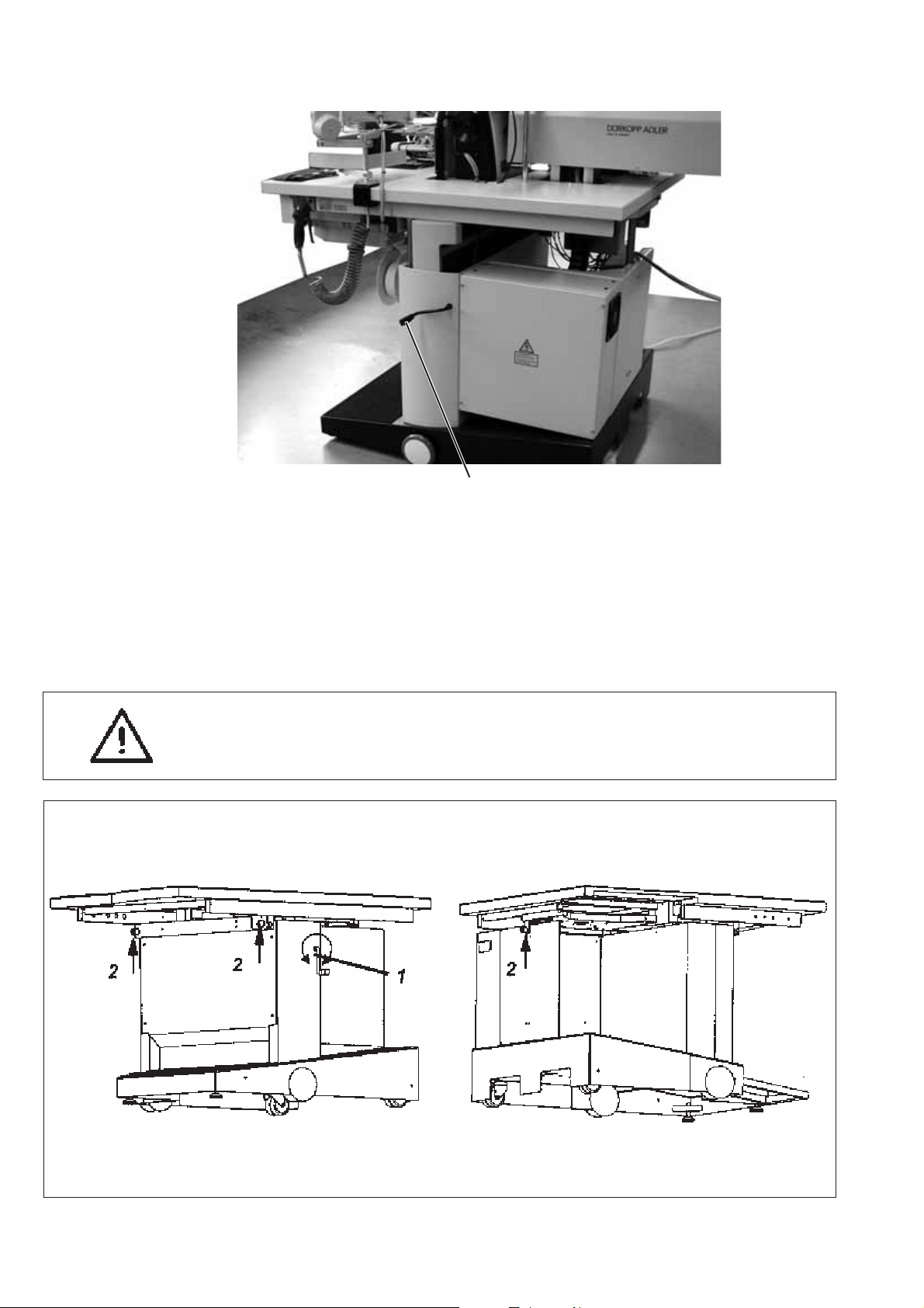
3.1 Transport
For in-house transport the stand is equipped with four castors.
ATTENTION !
Do not lift the sewing unit at the table tops.
Use an elevating platform truck or a forklift truck.
1
ATTENTION!
Before commissioning the sewing unit screw out the stand feet 2 and 3
until a secure footing is achieved.
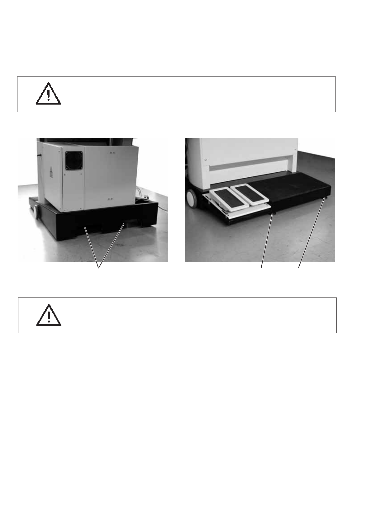
Lifting the sewing unit
–
Push the elevating platform truck or the forklift forks into the
openings 1 at the back of the sewing unit.
Rolling the sewing unit
–
For transport purpose unfasten the stand feet 2 and 3 by turning
them to the right.
–
After transport secure the sewing unit by turning the stand feet 2
and 3 to the left.
23
4
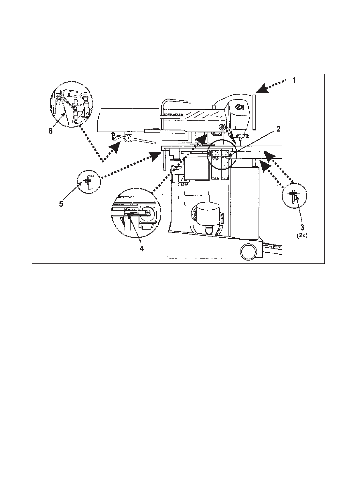
3.2 Removing the securing devices
Before installing the sewing unit all six securing devices have to be
removed.
If the sewing unit has to be transported to another place, please use
the securing devices again.
5
3.3 Setting the working height
1
The working height can be set between 77 cm and 108 cm
(measured up to the upper edge of the table top).
The sewing unit is set to the lowest working height of 77 cm by the
manufacturer.
–
Turn the table top to the desired height with crank 1.
–
To the right = Table top higher
–
To the left = Table top lower
ATTENTION: Danger of breakage !
Crank 1 must not be actuated before the 3 securing screws 2 have
been removed.
6

3.4 Adjusting the foot pedals
12 3 4 5
The distance of the foot pedals to the operator is adjustable.
–
Loosen screws 1, 2, 4 and 5.
–
Push the base plate 3 with the pedals into the desired position.
–
Tighten screws 1, 2, 4 and 5 again.
7

4. Attaching the machine parts removed for shipping
4.1 Thread reel holder
321
–
Insert the thread reel holder 2 in the drill-hole of the table top
and fasten it with nut 4 underneath the table top.
–
Mount and align the reel plate 1 and the unwinding arms 3 as
shown in the illustration.
4
8

4.2 Cylinder for pick-up folder stroke (745-34 B/F)
432 1
–
Remove the securing device and swivel the cylinder upwards.
–
Fasten the cylinder fixture 1 to plate 3 with screws 4.
–
Move the fixture for the pick-up folder by hand.
The movement must be fingertip easy over the whole cylinder
stroke.
Correction
–
Loosen screws 3 a little and move the fixture for the pick-up folder
over the whole cylinder stroke.
In the course of this the cylinder fixture aligns itself.
–
Tighten screws 3.
–
Check the free movement once again.
9

4.3 Workpiece boxes
4 321
–
Fasten the workpiece boxes onto rod 2.
For this purpose push the clamping pieces 4 and 3 on rod 2, align
the height and clamp them firmly by tightening the screws.
–
Loosen the screw at clamping lever 1 and align the workpiece
boxes to the sewing station.
–
Tighten the screw at clamping lever 1.
10

4.4 Fastening the holder for control panel, bobbin winder and right-hand tray
6 543 21
Control panel
–
Fasten angle 6 and control panel 5 to bolt 3 with nut 4.
–
Fasten cable 1 to bolt 3 with screw 2.
Bobbin winder and tray
–
Push holder 11 with angle 10 onto the table top and tighten with the
screw.
–
Align the arms 9 and 12.
–
Fasten the tray 8 to the lower arm.
–
Fasten the bobbin winder 7 to the upper arm.
See chapter 5.2 for connecting the bobbin winder.
12 11 10 9 8 7
11

4.5 Table extensions (optional equipment)
4.5.1 Table extension for working method with bundle clamp carriage (Order No. 0745 597674)
321
–
Fasten the table extension 3 onto the table top brace with the
screws 2.
–
Loosen screws 1 slightly.
Create a clearance to the table top by shifting the table extension 3.
This clearance is required for the free passage of the positioned
pocket bag.
12

4.5.2 Table extension for stacking to the side (Order No. 0745 597684)
43
–
Fasten table extension 2 to the front of the rest table brace with the
screws 1.
–
Screw angle 3 on table top 4 with two screws.
21
13

4.6 Throw-over stacker (optional equipment)
21
43 2
27 56
98
14
The throw-over stacker 1 (Order No. 0745 597554) is fastened to the
stand of the sewing unit with mounting pipe 2.
–
Fasten the mounting pipe 2 in the right stacking opening 4 with
screws, washers and shackle 3.
–
Push the throw-over stacker towards the stand of the sewing unit.
–
Fasten spars 5 and 6 on spar 2 with the shackle and the two
brackets 7.
–
Insert the coupling plug of the compressed air supply (thick hose)
into hose coupling 8.
–
Insert the coupling plug of the control conduit (thin hose) into
coupling 9.

Aligning the stacker
–
Shift the stacker laterally in such a way that spar 4 is flush with the
table top edge 3.
–
Loosen the clamping screw 6.
–
Move the stacker up on cylinder 5 so that the moving smoother 7
does not hit the table top 1.
–
Tighten the clamping screw 6.
15

5. Electrical connection
ATTENTION!
Any work on the electrical equipment of the sewing unit must
only be carried out by electricians or correspondingly instructed
persons.
The mains plug must be pulled out.
5.1 Connecting the control panel DACII C
21
–
Carefully insert plug 1 into the rear panel of the control panel.
–
Tighten the screws 2 of plug 1.
5.2 Connecting the external bobbin winder
–
Insert the plug of the bobbin winder into the socket 3 underneath
the table top and secure with a cap nut.
–
Bundle the leads for the bobbin winder and the external control
panel with two cable clamps 5 and 6.
5.3 Making the mains connection
–
Connect the mains plug.
654 3
16

5.4 Checking the nominal voltage
ATTENTION!
The nominal voltage indicated on the type plate and the mains voltage
must correspond.
2
25 4
6
5
4
1
The adaptation to the local mains voltage has to be done at the
terminal strip 3 and the transformer 6 in the control cabinet.
–
Screw off the cover 1 at the control cabinet.
–
Loosen screws 2 and 5 and remove the guard 4.
–
Check the arrangement of the connections to terminal strip 3 and
transformer 6.
(see circuit diagram, sheet 2 and 3).
–
If necessary, change the connections according to the local mains
voltage.
–
Put the guard 4 on again and screw it on with the screws 2 and 5.
–
Put the cover 1 on the control cabinet again and screw on.
bl = blue / sw = black / bn = brown
3
17

5.5 Checking the nominal voltage of the vacuum device (optional equipment)
1
The adaptation to the local mains voltage has to be done at the
terminal strip in control box 1.
–
Screw off the cover of control box 1.
–
Check the arrangement of the connections to the terminal strip.
(see circuit diagram, sheet 1).
–
If necessary, change the connections according to the local mains
voltage.
–
Put the cover on the control box 1 again and screw on.
5.6 Direction of rotation of the sewing motor
The sewing unit is equipped with the latest step motor technology. A
check of the direction of rotation is not required because it is
automatically set by the control.
18

6. Pneumatic connection
2
For the operation of the pneumatic components the sewing unit has to
be supplied with anhydrous compressed air.
ATTENTION !
For a trouble-free function of the pneumatic control procedures the
compressed air supply must operate as follows:
Even at the moment of the highest air consumption the minimum
operating pressure must not drop below 6 bar.
In case of a too high loss of pressure:
–
Increase the compressor output.
–
Increase the diameter of the compressed air hose.
3
1
4
Connecting the maintenance unit for compressed air
–
Connect the connection hose 1 (Order No. 0797 003031) to the
cut-off cock 2 and the compressed air line by means of a hose
coupling ¼ “.
Adjusting the operating pressure
–
The operating pressure amounts to 6 bar.
It can be read off at the manometer 4.
–
For adjusting the operating pressure lift the twist handle 3 and turn
it.
–
Turning in clockwise direction = the pressure is increased
–
Turning counter-clockwise = the pressure is reduced
ATTENTION !
No oil-bearing compressed air must be fed from the compressed air
line.
Behind the filter cleaned compressed air is withdrawn as blowing air
for cleaning machine parts and for blowing workpieces out.
Oil particles contained in the blowing air lead to malfunctions and
stains on the workpieces.
19

7. Connection to the factory-own vacuum unit
1
The suction unit facilitates the precise feeding and positioning of the
workpiece on the work table 1.
–
Connect the hose of the factory-own vacuum unit to the connection
valve 3.
Note:
In case no factory-own vacuum unit is available, the vacuum device
(Order No. 0745 597624) has to be ordered in addition.
ATTENTION !
When mounting the vacuum device (side-channel blower) it is
absolutely necessary to exchange the joint ring 2 (black) at the
connection valve against a filter ring (white) included in the
accessories.
32
20

8. Oil lubrication
1
Caution: Danger of injury !
Oil can cause skin rashes.
Avoid longer skin contact.
After contact wash yourself thoroughly.
ATTENTION !
The handling and disposal of mineral oils is subject to legal
regulations.
Deliver used oil to an authorized collecting station.
Protect your environment.
Be careful not to spill any oil.
For filling up the oil reservoirs use nothing but DA-10 lubricating oil or
an equivalent oil with the following specification:
–
Viscosity at 40° C: 10 mm
–
Ignition point: 150° C
DA-10 is available from the DÜRKOPP ADLER AG sales offices under
the following parts numbers:
250 ml-Container: 9047 000011
1 l - Container: 9047 000012
2 l - Container: 9047 000013
5 l - Container: 9047 000014
2
/s
32
23
Oil reservoir for the lubrication of the machine head
–
Fill oil reservoir 1 with oil through the drill-holes in the inspection
glass.
The oil level must be between the “Min” and “Max” markings.
Oil reservoir for the hook lubrication
–
Tilt the machine head up (see Operating Instructions, chapter 2.3).
–
Fill the oil reservoir 2 with oil up to the “max.” marking through
nipple 3 (see sketch).
21

9. Commissioning
After completion of the installation work a sewing test should be made.
–
Plug in the mains plug.
Caution: Danger of injury !
Switch off the main switch before threading in the needle and hook
thread.
Laser light.
Do not look into the light source.
–
Thread in the needle thread (see Operating Instructions,
chapter 2.5).
–
Thread in the hook thread (see Operating Instructions,
chapter 2.8).
–
Switch on the main switch.
The control is initialized.
The DÜRKOPP-ADLER logo briefly appears in the display of the
control panel.
–
Step back on the left pedal.
The reference run starts.
The transport carriage moves in its rear end position.
The reference run is necessary in order to get a defined initial
position of the transport carriage.
–
The display changes to the main screen of the sewing unit.
–
By actuating the left pedal the various steps of the positioning
procedure are triggered sequentially and the sewing cycle is
started.
The individual steps are dependent on the working method and the
equipment of the sewing unit.
22
ATTENTION !
At the sewing start the workpiece must lie under the feeding clamps.
Movement of the transport carriage without material damages the
coating of the feeding clamps.
–
For selecting the sewing program and for the further settings of the
control unit see Part 4: Programming Instructions 745-34.
–
Positioning and operation are described in Part 1: Operating
Instructions 745-34.
 Loading...