


Manual, complete
745 - 34 Speedpocket
Sewing unit for runstitching
of rectangular piped pockets
Operating Instructions
Installation Instructions
Service Instructions
Instructions for programming DAC
1
2
3
4
Postfach 17 03 51, D-33703 Bielefeld • Potsdamer Straße 190, D-33719 Bielefeld
Telefon + 49 (0) 5 21 / 9 25-00 • Telefax + 49 (0) 5 21 / 9 25 24 35 • www.duerkopp-adler.com
Ausgabe / Edition: 08/2005 Printed in Federal Republic of Germany Teile-Nr./Part.-No.: 0791 745171

745 - 34 Speedpocket
Manual, complete
Summary
Operating Instructions
Installation Instructions
Service Instructions
Instructions for programming DAC
Interconnection diagram
9870 745131 B
9890 745001 B
Pneumatic circuit plan
9770 745002

Index Page:
Part 3: Service Instructions 745-34 Speedpocket
1. General notes................................................ 3
1.1 Gauges .................................................... 4
1.2 Grooveinthearmshaftcrank ...................................... 5
2. Sewing machine head
2.1 Raising the sewing machine head .................................... 6
2.2 Removing / Installing the sewing machine head ............................ 8
2.3 Crankpinatthearmshaft......................................... 10
2.4 Needle bar linkage ............................................. 13
2.4.1 Removing the needle bar linkage .................................... 13
2.4.2 Removing a needle bar from the linkage ................................ 15
2.4.3 Disassembly of the needle bar ...................................... 16
2.4.4 Assembly of a needle bar ......................................... 16
2.4.5 Installation of the needle bars in the needle bar linkage ....................... 17
2.4.6 Installation of the needle bar linkage .................................. 19
2.4.7 Height of the needle bar linkage ..................................... 21
2.4.8 Aligning the needle bar linkage to the throat plate .......................... 22
2.4.9 Exchanging the needle holder ...................................... 23
2.5 Hook...................................................... 24
2.5.1 Hookshaftheight.............................................. 24
2.5.2 Adjusting the gear clearance of the hook drive ............................ 25
2.5.3 Looping stroke ................................................ 26
2.5.4 Height of the needle holders ....................................... 27
2.5.5 Distance between hook tips and needles ................................ 29
2.5.6 Needle protection .............................................. 31
2.5.7 Exchanging the hook ............................................ 32
2.5.8 Bobbin case holding wire ......................................... 33
2.6 Centerknife ................................................. 35
2.6.1 Removing / Installing the driving motor ................................. 35
2.6.2 Removing / Installing the switching cylinder .............................. 36
2.6.3 Adjustingtheknife ............................................. 37
2.7 Threadcontrollerspring.......................................... 39
2.8 Trimming and clamping device for the needle threads ........................ 40
2.8.1 Function ................................................... 40
2.8.2 Exchanging knife and thread catcher .................................. 41
2.9 Trimming and clamping device for the hook threads ......................... 43
2.10 Thread puller for the needle threads................................... 46
2.11 Synchronizer................................................. 47
2.12 Oillubrication................................................ 48
2.12.1 Hooklubrication............................................... 49

Index Page:
3. Transport carriage
3.1 Rearendposition.............................................. 51
3.1.1 Positionofthelimitswitchintheslottedhole ............................. 53
3.1.2 Distancebetweenswitchingscrewandlimitswitch.......................... 53
3.1.3 Stopguidefortransportcarriage..................................... 53
3.2 Changing the toothed belt ........................................ 54
3.3 Adjustingthebelttension......................................... 55
4. Feeding clamps
4.1 Measuring line for aligning the feeding clamps and the folder ................... 56
4.2 Aligning the feeding clamps as to the auxiliary line .......................... 57
4.3 Feeding clamp stroke ........................................... 58
4.4 Distance between the feeding clamps and the folder sole ...................... 59
4.5 Front end position of the feeding clamp ................................. 60
5. Knives for corner incision
5.1 Presetting .................................................. 61
5.2 Aligningthecornerknifestationastotheseams........................... 62
5.3 Adjustingtheslantofthecornerincisions ............................... 64
5.4 Exchanging the corner knives ...................................... 65
6. Laser markings ............................................... 66
6.1 Aligningthemarkings ........................................... 67
7. Reflected light barriers for flap scanning
7.1 Swivelarm.................................................. 68
7.2 Aligningthelightbarriers ......................................... 69
8. Aligning the folding station plate as to the measuring line ................... 70
9. Positioning the sewing machine head as to the table top .................... 71
10. Folder
10.1 Proper fastening............................................... 72
10.2 Aligning the folder as to the middle of the pocket opening ...................... 73
10.3 Liftingmotionofthefolder......................................... 74
10.4 Position of the folder to the needles ................................... 76
10.5 Guideplatesatthefolder......................................... 77
11. Stacker
11.1 Positionofthepincerstothetabletop ................................. 78
11.2 Heightofthepincer............................................. 78
11.3 Positionandclosingofthepincers.................................... 79
11.4 Cylinder speed ............................................... 80
11.5 Positionoftherestplate.......................................... 80
11.6 Swivellingthestackeraside........................................ 81
12. Exchange the control unit ........................................ 81

1. General notes
The service instruction manual on hand describes the setting of the
sewing unit 745-34 in an appropriate sequence.
ATTENTION !
Some of the setting positions are interdependent.
Therefore it is absolutely necessary to carry out the individual settings
following the described order.
The operations described in the service instructions must only
be executed by qualified s taff and correspondingly instructed persons
respectively!
Danger of breakage !
Before the sewing unit is put into operation again after having been
disassembled the necessary adjustments have to be carried out
according to the service instructions.
Before any adjusting operations of parts involved in the stitch
formation are made:
–
Insert a new needle without any damage.
Caution: Danger of injury !
Before repair, converting and maintenance work is done:
–
Switch the main switch off and disconnect the sewing unit from the
pneumatic supply system.
Exception:
Adjusting operations carried out with the help of test or setting
programs.
Adjusting operations and function tests when the sew ing unit is
running
–
Carry out adjusting operations and function tests of the running
sewing unit
only under observation of all safety measures and with utmost
caution.
Adjusting operations in the needle zone
–
Parts which can lead to injuries have to be removed before carrying
out the adjusting operations.
Exception:
The parts are absolutely necessary for the adjusting operations.
3

1.1 Gauges
The gauges listed below allow a precise setting and testing of the
sewing unit.
The locking peg 1 belongs to the standard accessories of the sewing
unit. It serves to stake out the position A (looping stroke).
The setting gauges marked with *) are available on inquiry.
Position Setting gauge Order No. Use
1 Locking peg 0211 000700 Looping stroke position
2 *) Gauge 0246 002591 Crank pin to arm shaft
3 *) Gauge 0244 001001 Height of hook shaft
4 *) Measuring bridge 0212 004942 Height of needle holder
5 *) Measuring pin 0216 001070 Height of needle holder
6 *) Adjusting pin 0244 001014 Lateral hook distance
4

1.2 Groove in the arm shaft crank
1
2
3
The arm shaft crank 1 is provided with a groove 2 (5 mm).
The machine head can be staked out with the locking peg through
drill-hole 3.
Now the machine head is in looping stroke position
(position A).
5
2. Sewing machine head
2.1 Raising the sewing machine head
For maintenance work the machine head can be r aised.
For this purpose the transport carriage must be in its rear position.
Caution: Danger of injury !
Switchthemainswitchoff.
Raise the machine head only with the main switch switched off.
1
45
3
6
6
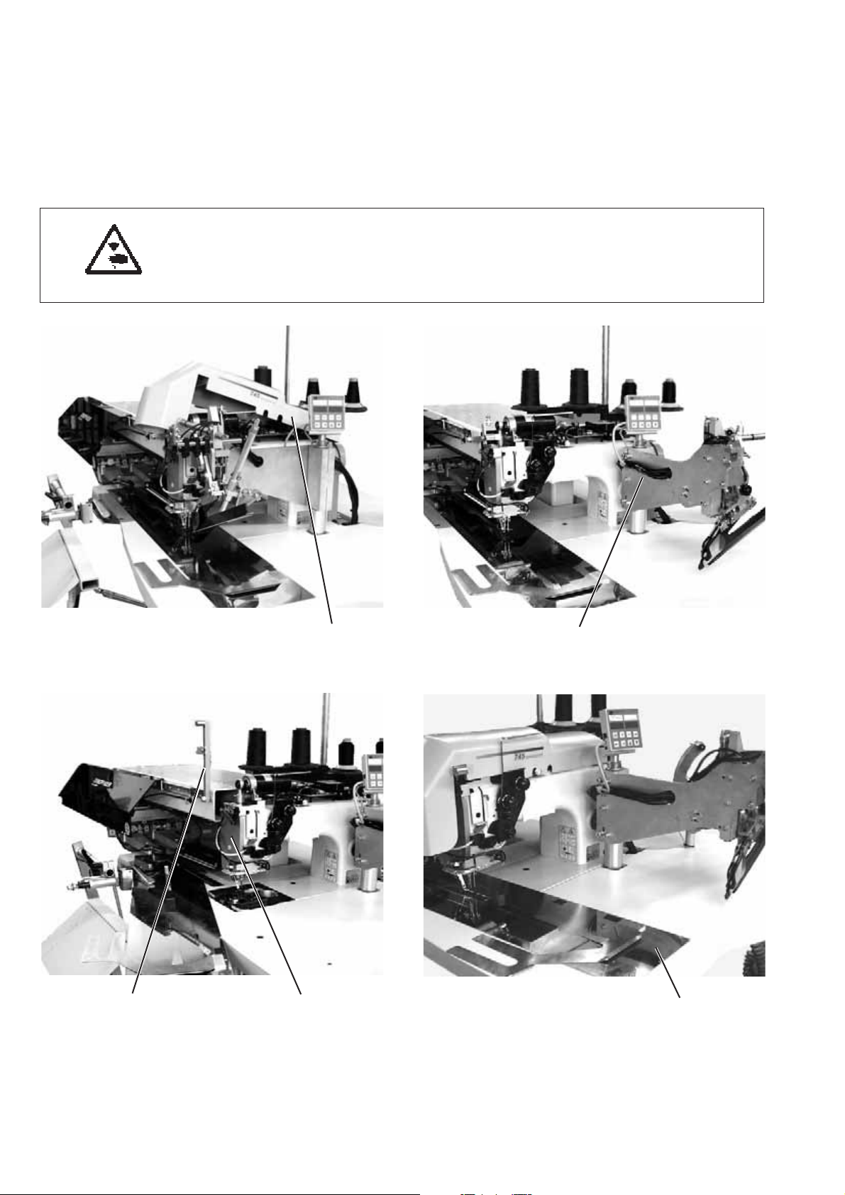
Raising the machine head
–
Remove the covering cap 1.
For this purpose lift the covering cap at the front and at the back so
that the arrest is released. Lift the covering cap carefully.
–
Swivel the folding station 3 out by 90°.
–
Swing the locking peg 4 upwards.
–
Lift the fabric sliding sheet 6 at the front and swing it to the left.
–
Lift the machine head in the area of head cover 5 and raise it
carefully.
Pawl 2 snaps in additionally.
The area underneath the machine table is accessible for cleaning.
Caution: Danger of injury !
Do not reach into the table top cutout when the machine head is
raised.
Swinging the machine head back
–
Hold the machine head in the area of head cover 5.
–
Release pawl 2.
–
Swing the machine head back carefully.
Attention: Danger of breakage!
Hold the machine head tight until it finally rests on.
–
Insert the fabric sliding s heet
–
Swivel the locking lever 4 downwards.
–
Swing the folding station 3 back carefully and let it catch in the
locking lever.
–
Put on the covering cap 1 and let it snap in again.
2
7

2.2 Removing / Installing the sewing machine head
For repair work or an easier c hange to another needle distance the
machine head can be removed.
For this purpose the transport carriage must be in its rear position.
Caution: Danger of injury!
Switch the main switch off and disconnect from the pneumatic net.
Remove and install the machine head only with the main switch
switched off.
1 3
45
6
8
98
Removing the machine head
–
Remove the covering cap 1.
For this purpose lift the covering cap at the front and at the back so
that the arrest is released. Lift the covering cap carefully.
–
Swivel the folding station 3 out by 90°.
–
Swing the locking lever 4 upwards.
–
Lift the fabric sliding sheet 6 at the front and swing it to the left.
–
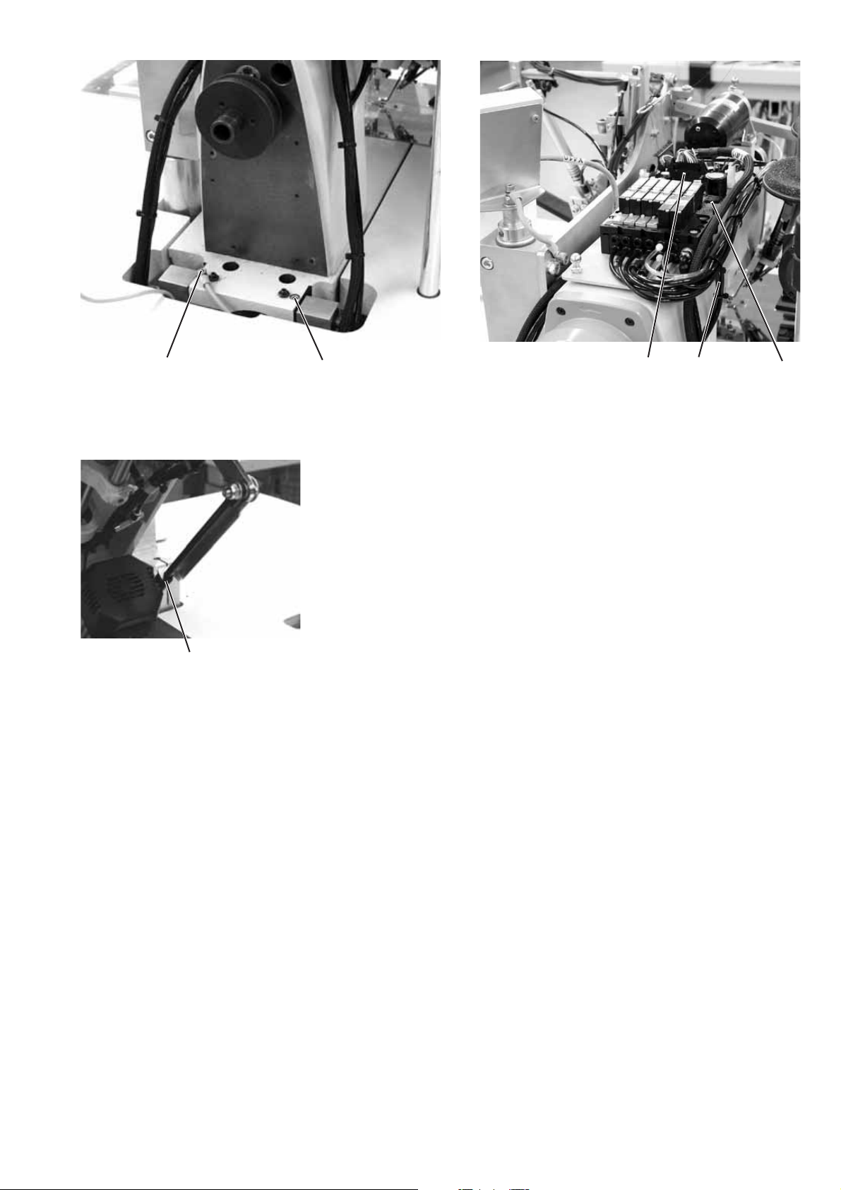
Pull off plug 7 from the circuit board.
–
Pull off the main pneumatic hose 11 from the solenoid valve
block 10.
–
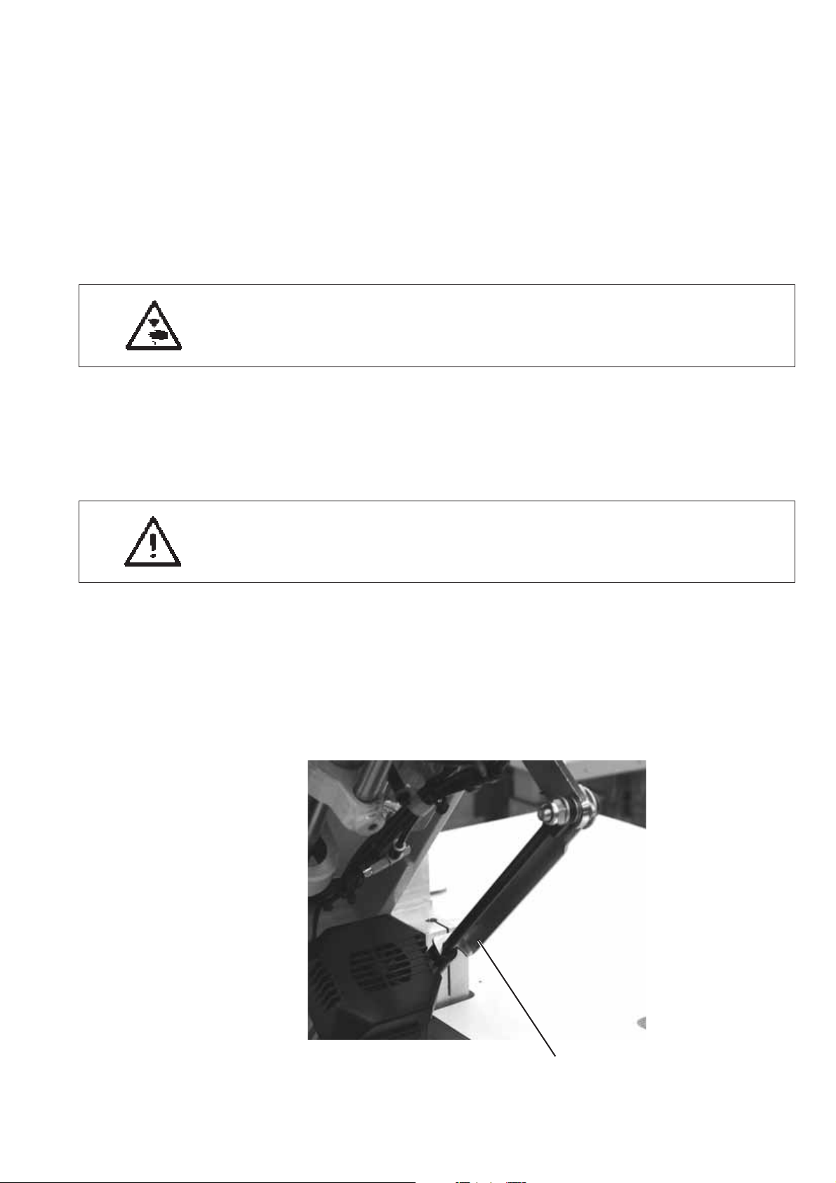
Loosen the gas shock absorber connection 2.
–
Unscrew screws 8 and 9.
–
Pull off the plug from the motor at the control cabinet and
2
disconnect the plug connection from the proximity switch.
–
Lift out the machine head carefully with an appropriate auxiliary
tool.
Installing the machine head
–
Carefully insert the machine head into the cutout for the head with
an appropriate auxiliary tool.
–
Screw the machine head tight with the screws 8 and 9.
–
Re-establish the gas shock absorber connection 2.
–
Connect the pneumatic hose 11 to the solenoid valve block 10.
–
Put plug 7 on the circuit board again.
–
Insert the fabric sliding s heet.
–
Swing the locking lever 4 downwards.
–
Swing the folding station 3 back and let it catch.
–
Put on the covering cap 1 and let it snap in.
711 10
9

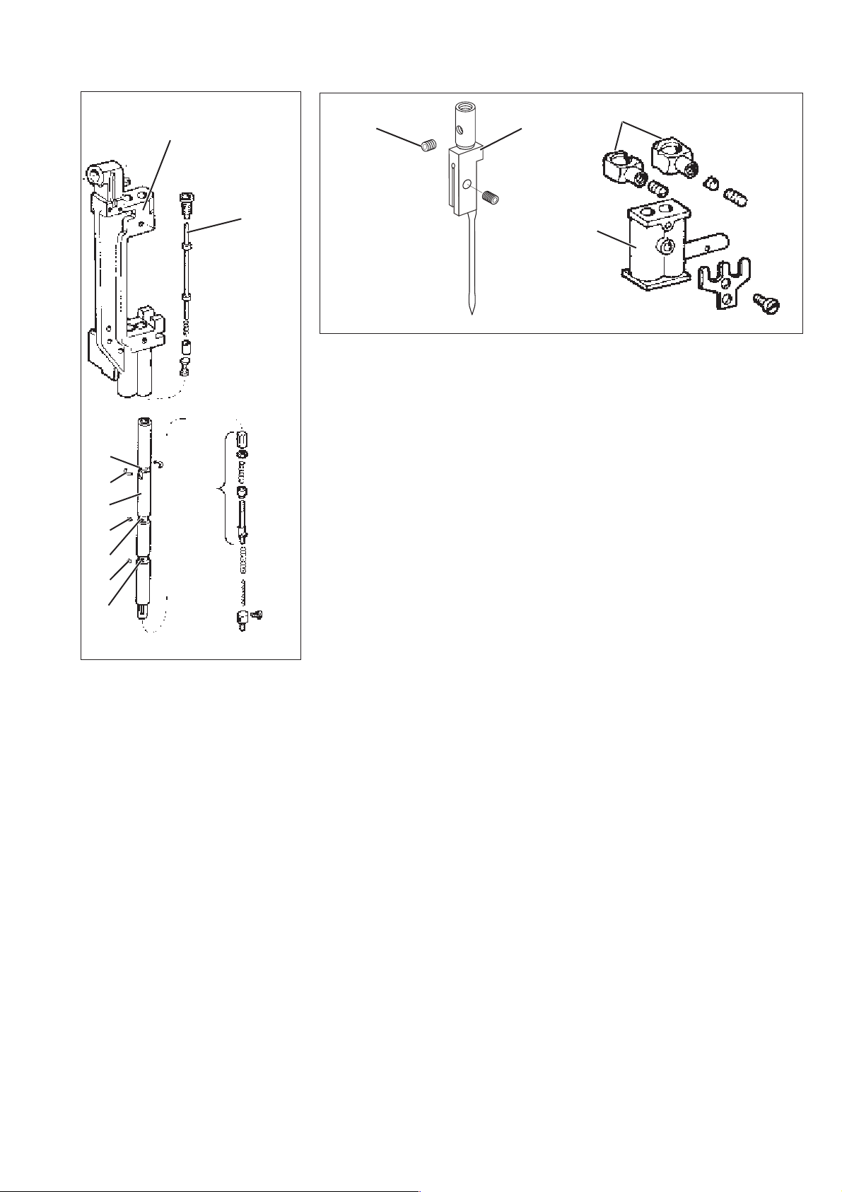
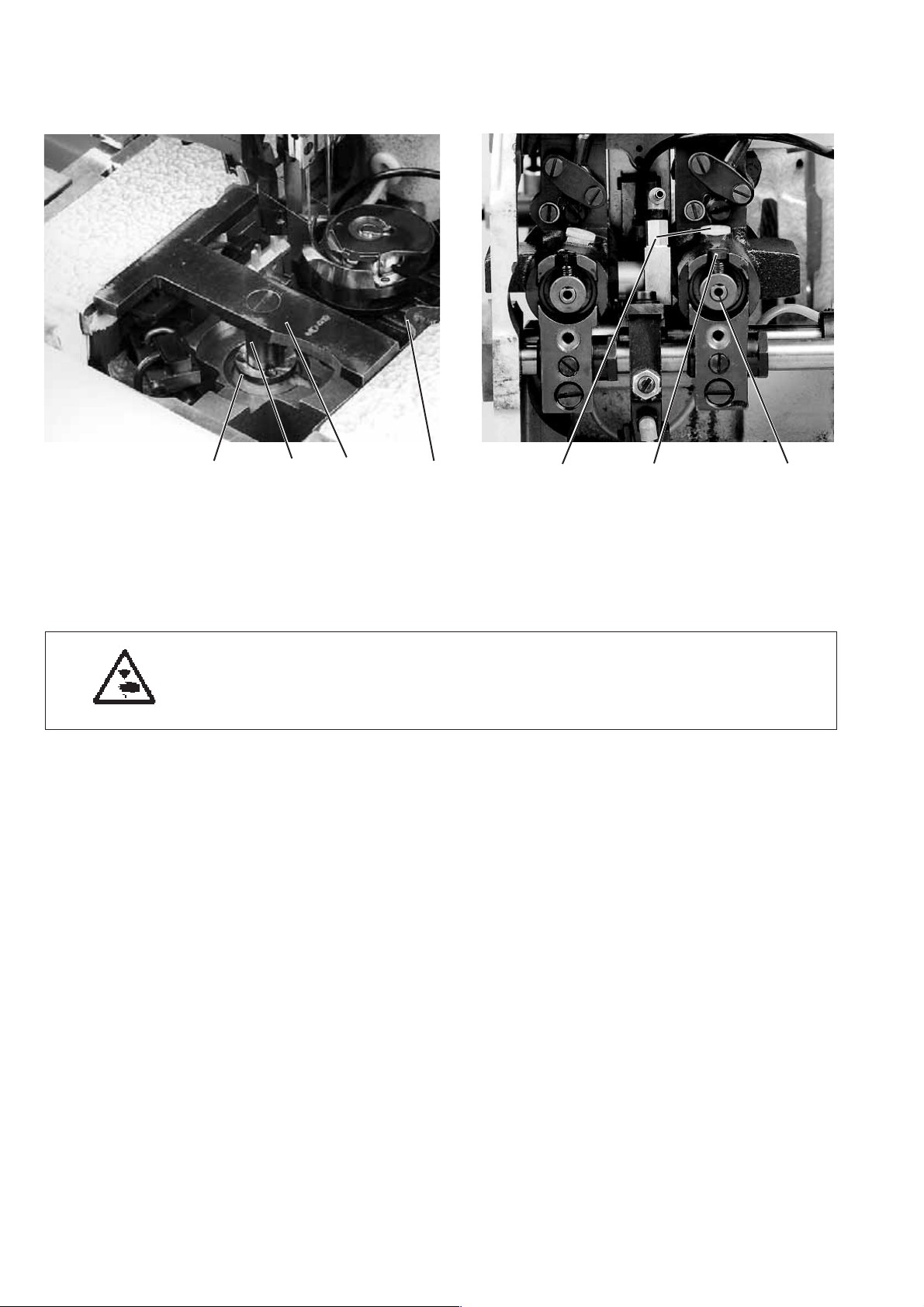
2.3 Crank pin at the arm shaft
The distance between the eccentric crank pin 1 and the arm shaft 4
determines the needle bar stroke and thus the upper dead centre of
the needle bars.
ATTENTION !
The crank pin 1 has been precisely set by the manufacturer!
After exchanging the thread lever the crank pin 1 has to be readjusted.
1
1
4
The adjustment of the crank pin 1 is done with the gauge 7
(Order No. 0246 002591).
It is not necessary to remove crank and arm shaft for the adjustment.
10
7
898
Caution: Danger of injury !
Switchthemainswitchoff.
Adjust the crank pin only with the main switch switched off.
–
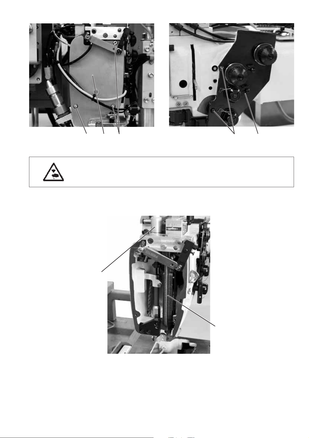
Remove the head cover 9 after loosening the fastening screws 8.
–
Swivel the thread tension plate 10 sideways after loosening the
fastening screws 11.
13
11 1 0
12
–
Remove the needle bar linkage 12 (see chapter 2.4.1).
–
Remove the switching cylinder 13 for the center knife drive
(see chapter 2.6.2).
11

1
2
3
5
6
–
Detach the needle bar tie rod from the crank pin 1 after unscrewing
its fastening screws (ATTENTION left-hand thread) and pull it off
with the needle cage.
–
Turn the handwheel until the Allen screws 2 point downward.
In this position the screws are accessible.
–
Loosen the Allen screws 2.
–
Loosen the support bolt 3.
The screw is accessible through drill-hole 13.
–
Put the pivots of gauge 7 in the insertion bores 6.
–
Turn the crank pin 1 in such a way that it reaches in the cutout of
the gauge.
–
Press the crank pin 1 on.
The thread lever 5 must have a minimum axial backlash for the
lubrication.
–
Tighten Allen screws 2 and support bolt 3.
–
Remove gauge 7.
12
13
–
Turn the handwheel and check the free movement of the upper
shaft.
–
Put the needle bar tie rod with the needle cage on the crank pin 1
and tighten the fastening screws. (ATTENTION left-hand thread).
–
Mount and adjust the needle bar linkage (see chapter 2.4.1).
–
Mount the switching cylinder for the center knife drive
(see chapter 2.6.2).
7

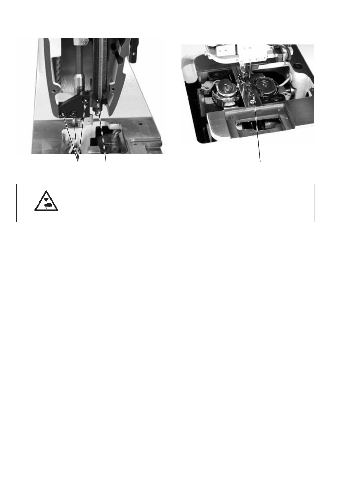
2.4 Needle bar linkage
2.4.1 Removing the needle bar linkage
6
121
Caution: Danger of injury!
Switchthemainswitchoff.
Remove the needle bar linkage only w ith the sewing unit switched off.
–
Unscrew the screws 1 and take off the head cover 2.
–
Loosen the screws 3 and 5 and pull off the thread puller 4.
54 3
6
7
–
Unscrew screws 7.
–
Unscrew screw 6.
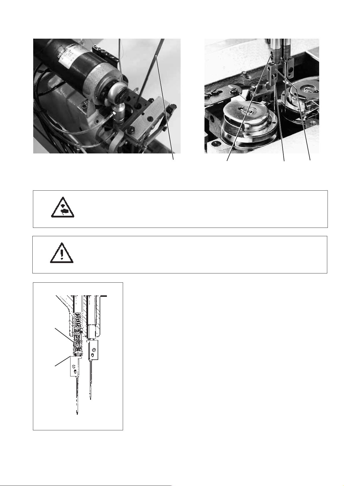
13

13
12
11
9
10
–
Loosen the counternut 12.
–
Loosen the adjusting screw 13 a bit.
ATTENTION !
Do not loosen both adjusting screws 13.
With the two adjusting screws 13 the correct height of the linkage
frame has been set by the manufacturer.
ATTENTION !
Avoid damage to the oil wick when taking off the needle bar.
Note the position of the oil wick for the subsequent assembly.
–
Carefully remove the support p late 9 with the needle bar linkage 10
from the stop pin 11.
This is facilitated by slight turning motions.
14

2.4.2 Removing a needle bar from the linkage
1
15
14
16
4
5
6
7
8
32
13
12 11
–
Loosen the clamping screw 1.
–
Pull out the bearing bolt 2
–
Pull off the support plate 3 from the needle bar linkage.
–
Unscrew the screws 8 and 10.
–
Remove the guide rail 9.
–
Actuate both decoupling bars 15 and push the yoke 7 downwards
to half the needle bar stroke.
–
Unscrew the safety bolt 6 of the clamping r ing 4 as well as the
fastening screw 5 located below.
–
Remove the two securing halves 14. They are located in the
annular slot 13 and become visible after pushing down the
clamping ring 4.
–
Shift the switching block in such a way that the two decoupling
bars 15 are not actuated.
–
Shift the yoke 7 slowly up the needle bar until the three upper
coupling balls 12 come out.
9
10
ATTENTION !Take care that the balls do not get lost - they are
under spring pressure.
–
Pull the needle bar downward out of the linkage 16.
ATTENTION !The three lower balls 11 can drop out of the ball
holes of the needle bar.
15

2.4.3 Disassembly of a needle bar
2
1
–
Remove the linkage 16 and the needle bar as described
under 2.4.1.
–
Screw off the screw 1 and unscrew the needle holder 2.
–
Unscrew the screw 15 and loosen the spring counter bearing 16.
ATTENTION !The spring counter bearing is under spring pressure.
Before loosening the screw 15 support the spring counter bearing
withapinÆ 4 mm inserted in the needle bar from below.
–
Take off the parts located in the needle bar one after the other from
below.
2.4.4 Assembly of a needle bar
3
4
5
6
7
8
19
9
10
17
18
11
12
13
–
Screw the locking screw 3 tightly into the needle bar.
–
Pre-assemble the lower coupling bar 17 in the sequence as per the
illustration opposite.
–
Tighten nut 9 and counter-rotate the acorn nut 8 in such a way that
there is a distance of 30.5 mm between the lower edge of taper
socket 11 and the top edge of acorn nut 8.
Note
This dimension has to be observed in any case so that the
retaining force of the coupling necessary for the needle penetration
is achieved.
–
Put spring 5 and bush 6 on the thinner shaft extension of the
decoupling bar 4.
–
Push the thicker shaft extension of the decoupling bar 4 into the
needle bar 18 from below until it emerges on top of locking screw 3.
–
Push the following parts into the needle bar: first the conical bolt 7
with the cylindrical part showing upwards, then the pre-assembled
coupling bar 17 and finally spring 13 with spring 14 as well as
spring counter bearing 16.
–
Screw the spring counter bearing 16 tight by means of screw 15.
–
Press down the decoupling bar 4 repeatedly and check whether the
bars inside the needle bar are movable freely and flexibly.
16
14
15
16
2.4.5 Installation of the needle bars in the needle bar linkage
1
12
11
2
–
Insert the needle bar 7 in the linkage 10 from below.
–
Insert the needle bar in yoke 14 and clamping ring 13. The thin side
of the clamping ring must point to the other needle bar and its
9
8
7
6
5
4
3
indentation must point upwards.
–
Push up the needle bar so that the three lower ball holes 3 are still
below the linkage.
–
Insert three balls 4 in the lower ball holes 3. Use some grease to
avoid that the balls drop out.
–
Push the needle bar upwards so that the lower balls disappear and
the upper ball holes 5 become visible.
–
Insert the three balls 6 in the upper ball holes 5.
–
Hold the needle bar tight and press the decoupling bar 2 into the
needle bar.
–
Simultaneously pull the yoke 14 down half over the upper balls 6.
13
14
ATTENTION ! Now the needle bar and the yoke must not be shifted
any more because otherwise the balls being under spring pressure
might come out.
–
Push the clamping ring 13 down the needle bar until the annular
slot 9 lies exposed.
–
Place the two securing halves 8 in the annular slot. Push the
clamping ring 13 upward as far as it will go so that the securing
halves lie in the indentation.
–
Press the yoke 14 upward against the clamping ring 13 as far as it
will go so that the needle bar is coupled with the yoke.
–
Screw in needle holder 11 and fasten by means of screw 12.
–
Turn the needle bar in such a way that the fronts of both needle
holders are at the same level.
17
13
15
16
2
6
16
17
14
–
Fasten the clamping ring 13 on the needle bar. Please observe that
both clamping rings 13 with their round extensions are guided in
clevis 17 fastened on the yoke. After tightening the fastening
screw 15 the safety bolt 16 has to be tightened, too.
–
Screw on the guide rail 19. It avoids turning of a disconnected
needle bar.
ATTENTION !
When the needle bar linkage is removed and the needle bar is
disconnected, the yoke 14 must not be pushed down too far. The
upper balls 6 might come out unintentionally.
–
Note:
The precise needle height as to the hook has to be adjusted after
the installation of the linkage according to chapter 2.5.4 “Height of
the needle holders”.
18
19
18

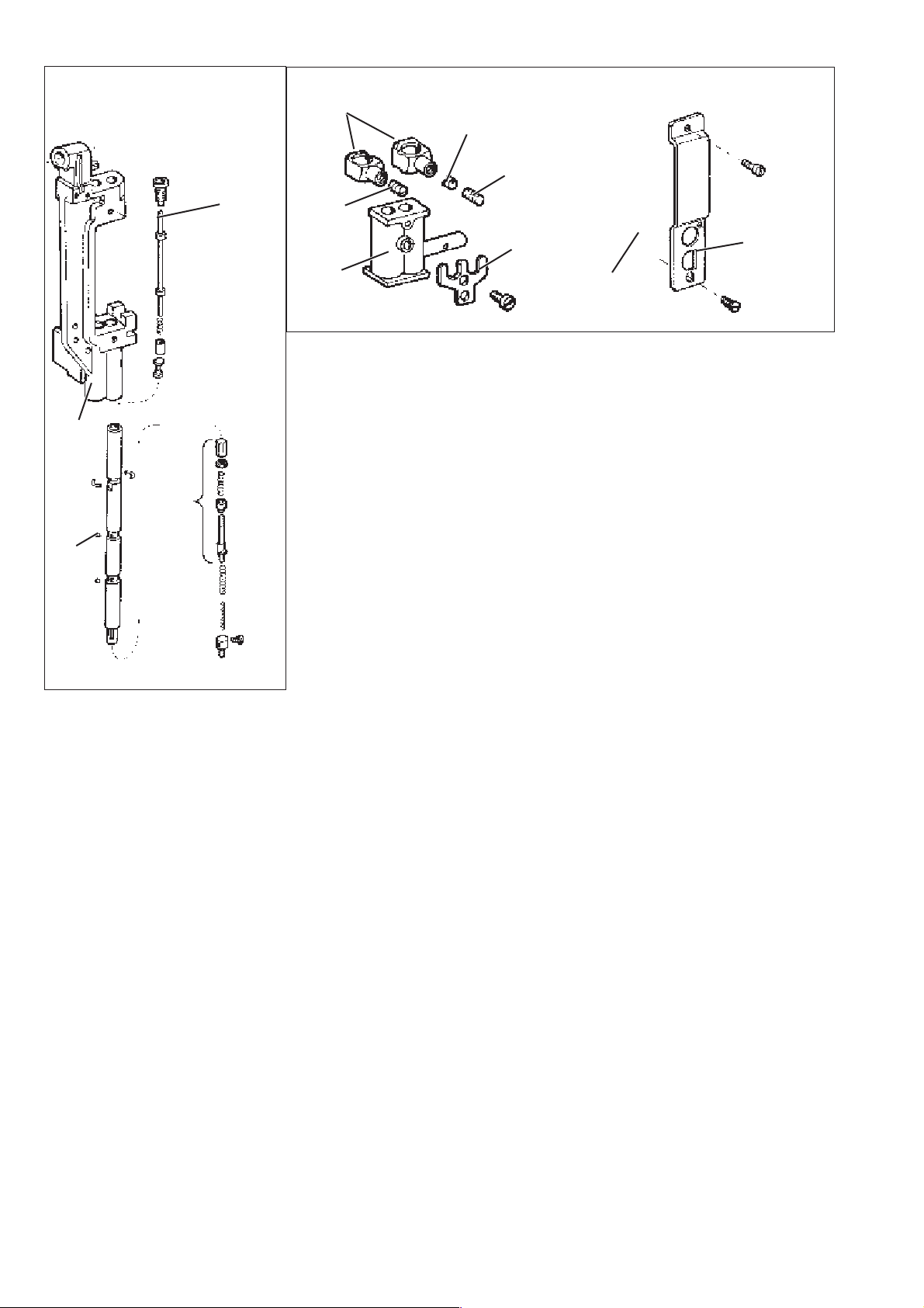
2.4.6 Installation of the needle bar linkage
21
3
8
7
654
Caution: Danger of injury !
Switchthemainswitchoff.
Mount the needle bar linkage only with the sewing unit switched off.
9
–
Push the support plate 4 on the needle bar linkage 5.
–
Press the bearing bolt 10 into the support plate and the needle bar
linkage.
–
Tighten the clamping screw 9.
The needle bar linkage must be close to the support plate 4, but
must be freely movable nevertheless.
–
Carefully push the support plate 4 with the needle bar linkage 5 on
the stop pin 6.
–
Insert the fastening screw 8 and tighten slightly.
–
Put the adjusting screw 3 (height of needle bar linkage) next to the
stop pin 6 and secure with counternut 7.
–
Tighten the guide plate 1 w ith the two screws 2.
–
Insert the needle and align the needle bar linkage as to the throat
plate.
–
Tighten screws 8.
–
Check the height of the needle bar linkage (see chapter 2.4.7).
45 10
19

9
13
12
11
10
–
Push the thread puller 11 on the pins 9 and 12 and tighten with
screws 10 and 13.
–
Adjust the thread puller ( see chapter 2.10).
20

2.4.7 Height of the needle bar linkage
0,2 mm
121
Caution: Danger of injury !
Switchthemainswitchoff.
Check and adjust the height of the needle bar linkage only with the
sewing unit switched off.
Standard checking
If the two needle bars in the top dead centre are engaged, there must
be a distance of 0.2 mm between the yoke 4 and the needle bar
linkage 3.
–
Unscrew the screws 1 and take off the head cover 2.
–
Check the distance of 0.2 mm between yoke 4 and needle bar
linkage 3.
43
5
Correction
–
Unscrew the screws 1 and take off the head cover 2.
–
Slightly loosen screw 5 at the support plate.
–
Loosen the counternuts 7 and 9.
–
Set the linkage height with the screws 6 and 8 in such a way that
there is a distance of 0.2 mm between linkage 3 and yoke 4.
–
Tighten the counternuts 7 and 9.
–
Tighten screw 5 at the support plate.
–
Mount the head cover again.
9876
21
2.4.8 Aligning the needle bar linkage to the throat plate
21
Caution: Danger of injury !
Switchthemainswitchoff.
Check and adjust the alignment of the needle bar linkage only with the
sewing unit switched off.
Standard checking
The needles should penetrate in the centre of the holes of throat
plate 3.
–
Insert new needles.
–
Slowly move the needle bars down by handwheel.
–
Check the position of the needles in the needle hole.
Correction
–
Loosen the screws 2.
–
Shift the needle bar linkage laterally in such a way that the needles
are in the centre of the needle holes.
–
Tighten the screws 2.
3
22
2.4.9 Exchanging the needle holder
1
Caution: Danger of injury !
Switchthemainswitchoff.
Check and exchange the needle holder only with the sewing unit
switched off.
ATTENTION !
For changing a needle holder the needle bar in question must be in
position “down”.
The other needle bar has to be disconnected.
–
Loosen the screw 3.
–
Remove the needle from needle holder 2.
–
Press down the switch bar of the needle bar with an Allen k ey 1
and hold it pressed.
–
Switch the needle bar off by turning the handwheel.
–
4
2
Keep on turning the handwheel.
The actuated needle bar switches off.
–
Keep on turning the handwheel until the needle bar is in position
“down”.
–
Loosen the screw 4.
–
Unscrew the needle holder 2 from the needle bar.
–
Screw in a new needle holder.
–
Adjust the height of the needle holder (see chapter 2.5.4).
–
Tighten the screw 3.
–
Check the penetration of the needle into the needle hole.
–
Check lateral distance of the needle to the hook
(see chapter 2.5.5).
The exchange of the s econd needle holder is done likewise.
432
23
2.5 Hook
2.5.1 Hook shaft height
123 4 65 7
Standard checking
The distance between the throat plate support 4 and the flange
surface 1 of the hook shaft must amount to 17.7 mm.
The exact height of the hook shafts is set by means of gauge 3 (order
number 0244 001001).
Caution: Danger of injury !
Switchthemainswitchoff.
Check and adjust the hook shaft height only with the sewing unit
switched off.
–
Remove the throat plate.
–
Remove both hooks (see chapter 2.5.7).
–
Place the gauge 3 on the throat plate support 4.
The measuring bush 2 of the gauge must reach over the hook shaft
journal.
–
Check whether the flange surface 1 of the hook shaft abuts on the
measuring bush 2 of the gauge.
Correction
–
Swing the machine head upwards (see chapter 2.1).
–
Remove the plastic stoppers 6.
–
Loosen the screws under the plastic stoppers.
–
Loosen the screws 5.
–
Push the flange surface 1 of the hook shaft under the measuring
bush 2 of the gauge. For this purpose put a screwdriver under the
flange surface 1. If the hook shaft stands too high, push it
downward by a slight knocking on the flange surface 1.
–
Tighten the screws under the plastic stoppers 6 in this position.
–
Push the bush 7 against the hook shaft as far as it will go.
–
Tighten the screws 5 on the surfaces of bush 7.
–
Mount hook and throat plate again (see chapter 2.5.7).
24
 Loading...